EP4074596B1 - Disque de frein avec fusible thermique intégré et procédé de fabrication d'un disque de frein avec fusible thermique intégré - Google Patents
Disque de frein avec fusible thermique intégré et procédé de fabrication d'un disque de frein avec fusible thermique intégré Download PDFInfo
- Publication number
- EP4074596B1 EP4074596B1 EP21290020.3A EP21290020A EP4074596B1 EP 4074596 B1 EP4074596 B1 EP 4074596B1 EP 21290020 A EP21290020 A EP 21290020A EP 4074596 B1 EP4074596 B1 EP 4074596B1
- Authority
- EP
- European Patent Office
- Prior art keywords
- fusible material
- brake
- brake disk
- material section
- shaft
- Prior art date
- Legal status (The legal status is an assumption and is not a legal conclusion. Google has not performed a legal analysis and makes no representation as to the accuracy of the status listed.)
- Active
Links
Images




Classifications
-
- F—MECHANICAL ENGINEERING; LIGHTING; HEATING; WEAPONS; BLASTING
- F16—ENGINEERING ELEMENTS AND UNITS; GENERAL MEASURES FOR PRODUCING AND MAINTAINING EFFECTIVE FUNCTIONING OF MACHINES OR INSTALLATIONS; THERMAL INSULATION IN GENERAL
- F16D—COUPLINGS FOR TRANSMITTING ROTATION; CLUTCHES; BRAKES
- F16D55/00—Brakes with substantially-radial braking surfaces pressed together in axial direction, e.g. disc brakes
- F16D55/02—Brakes with substantially-radial braking surfaces pressed together in axial direction, e.g. disc brakes with axially-movable discs or pads pressed against axially-located rotating members
- F16D55/22—Brakes with substantially-radial braking surfaces pressed together in axial direction, e.g. disc brakes with axially-movable discs or pads pressed against axially-located rotating members by clamping an axially-located rotating disc between movable braking members, e.g. movable brake discs or brake pads
-
- F—MECHANICAL ENGINEERING; LIGHTING; HEATING; WEAPONS; BLASTING
- F16—ENGINEERING ELEMENTS AND UNITS; GENERAL MEASURES FOR PRODUCING AND MAINTAINING EFFECTIVE FUNCTIONING OF MACHINES OR INSTALLATIONS; THERMAL INSULATION IN GENERAL
- F16D—COUPLINGS FOR TRANSMITTING ROTATION; CLUTCHES; BRAKES
- F16D65/00—Parts or details
- F16D65/02—Braking members; Mounting thereof
- F16D65/12—Discs; Drums for disc brakes
- F16D65/123—Discs; Drums for disc brakes comprising an annular disc secured to a hub member; Discs characterised by means for mounting
-
- B—PERFORMING OPERATIONS; TRANSPORTING
- B64—AIRCRAFT; AVIATION; COSMONAUTICS
- B64C—AEROPLANES; HELICOPTERS
- B64C27/00—Rotorcraft; Rotors peculiar thereto
- B64C27/04—Helicopters
- B64C27/12—Rotor drives
-
- B—PERFORMING OPERATIONS; TRANSPORTING
- B64—AIRCRAFT; AVIATION; COSMONAUTICS
- B64D—EQUIPMENT FOR FITTING IN OR TO AIRCRAFT; FLIGHT SUITS; PARACHUTES; ARRANGEMENT OR MOUNTING OF POWER PLANTS OR PROPULSION TRANSMISSIONS IN AIRCRAFT
- B64D35/00—Transmitting power from power plants to propellers or rotors; Arrangements of transmissions
-
- F—MECHANICAL ENGINEERING; LIGHTING; HEATING; WEAPONS; BLASTING
- F16—ENGINEERING ELEMENTS AND UNITS; GENERAL MEASURES FOR PRODUCING AND MAINTAINING EFFECTIVE FUNCTIONING OF MACHINES OR INSTALLATIONS; THERMAL INSULATION IN GENERAL
- F16D—COUPLINGS FOR TRANSMITTING ROTATION; CLUTCHES; BRAKES
- F16D55/00—Brakes with substantially-radial braking surfaces pressed together in axial direction, e.g. disc brakes
- F16D55/02—Brakes with substantially-radial braking surfaces pressed together in axial direction, e.g. disc brakes with axially-movable discs or pads pressed against axially-located rotating members
-
- F—MECHANICAL ENGINEERING; LIGHTING; HEATING; WEAPONS; BLASTING
- F16—ENGINEERING ELEMENTS AND UNITS; GENERAL MEASURES FOR PRODUCING AND MAINTAINING EFFECTIVE FUNCTIONING OF MACHINES OR INSTALLATIONS; THERMAL INSULATION IN GENERAL
- F16D—COUPLINGS FOR TRANSMITTING ROTATION; CLUTCHES; BRAKES
- F16D55/00—Brakes with substantially-radial braking surfaces pressed together in axial direction, e.g. disc brakes
- F16D55/24—Brakes with substantially-radial braking surfaces pressed together in axial direction, e.g. disc brakes with a plurality of axially-movable discs, lamellae, or pads, pressed from one side towards an axially-located member
- F16D55/26—Brakes with substantially-radial braking surfaces pressed together in axial direction, e.g. disc brakes with a plurality of axially-movable discs, lamellae, or pads, pressed from one side towards an axially-located member without self-tightening action
- F16D55/28—Brakes with only one rotating disc
- F16D55/30—Brakes with only one rotating disc mechanically actuated
-
- F—MECHANICAL ENGINEERING; LIGHTING; HEATING; WEAPONS; BLASTING
- F16—ENGINEERING ELEMENTS AND UNITS; GENERAL MEASURES FOR PRODUCING AND MAINTAINING EFFECTIVE FUNCTIONING OF MACHINES OR INSTALLATIONS; THERMAL INSULATION IN GENERAL
- F16D—COUPLINGS FOR TRANSMITTING ROTATION; CLUTCHES; BRAKES
- F16D55/00—Brakes with substantially-radial braking surfaces pressed together in axial direction, e.g. disc brakes
- F16D55/24—Brakes with substantially-radial braking surfaces pressed together in axial direction, e.g. disc brakes with a plurality of axially-movable discs, lamellae, or pads, pressed from one side towards an axially-located member
- F16D55/26—Brakes with substantially-radial braking surfaces pressed together in axial direction, e.g. disc brakes with a plurality of axially-movable discs, lamellae, or pads, pressed from one side towards an axially-located member without self-tightening action
- F16D55/28—Brakes with only one rotating disc
- F16D55/32—Brakes with only one rotating disc actuated by a fluid-pressure device arranged in or on the brake
-
- F—MECHANICAL ENGINEERING; LIGHTING; HEATING; WEAPONS; BLASTING
- F16—ENGINEERING ELEMENTS AND UNITS; GENERAL MEASURES FOR PRODUCING AND MAINTAINING EFFECTIVE FUNCTIONING OF MACHINES OR INSTALLATIONS; THERMAL INSULATION IN GENERAL
- F16D—COUPLINGS FOR TRANSMITTING ROTATION; CLUTCHES; BRAKES
- F16D65/00—Parts or details
- F16D65/005—Components of axially engaging brakes not otherwise provided for
-
- F—MECHANICAL ENGINEERING; LIGHTING; HEATING; WEAPONS; BLASTING
- F16—ENGINEERING ELEMENTS AND UNITS; GENERAL MEASURES FOR PRODUCING AND MAINTAINING EFFECTIVE FUNCTIONING OF MACHINES OR INSTALLATIONS; THERMAL INSULATION IN GENERAL
- F16D—COUPLINGS FOR TRANSMITTING ROTATION; CLUTCHES; BRAKES
- F16D65/00—Parts or details
- F16D65/02—Braking members; Mounting thereof
- F16D65/12—Discs; Drums for disc brakes
- F16D65/127—Discs; Drums for disc brakes characterised by properties of the disc surface; Discs lined with friction material
-
- F—MECHANICAL ENGINEERING; LIGHTING; HEATING; WEAPONS; BLASTING
- F16—ENGINEERING ELEMENTS AND UNITS; GENERAL MEASURES FOR PRODUCING AND MAINTAINING EFFECTIVE FUNCTIONING OF MACHINES OR INSTALLATIONS; THERMAL INSULATION IN GENERAL
- F16D—COUPLINGS FOR TRANSMITTING ROTATION; CLUTCHES; BRAKES
- F16D65/00—Parts or details
- F16D65/02—Braking members; Mounting thereof
- F16D65/12—Discs; Drums for disc brakes
- F16D65/128—Discs; Drums for disc brakes characterised by means for cooling
-
- F—MECHANICAL ENGINEERING; LIGHTING; HEATING; WEAPONS; BLASTING
- F16—ENGINEERING ELEMENTS AND UNITS; GENERAL MEASURES FOR PRODUCING AND MAINTAINING EFFECTIVE FUNCTIONING OF MACHINES OR INSTALLATIONS; THERMAL INSULATION IN GENERAL
- F16D—COUPLINGS FOR TRANSMITTING ROTATION; CLUTCHES; BRAKES
- F16D65/00—Parts or details
- F16D65/78—Features relating to cooling
- F16D65/84—Features relating to cooling for disc brakes
-
- F—MECHANICAL ENGINEERING; LIGHTING; HEATING; WEAPONS; BLASTING
- F16—ENGINEERING ELEMENTS AND UNITS; GENERAL MEASURES FOR PRODUCING AND MAINTAINING EFFECTIVE FUNCTIONING OF MACHINES OR INSTALLATIONS; THERMAL INSULATION IN GENERAL
- F16D—COUPLINGS FOR TRANSMITTING ROTATION; CLUTCHES; BRAKES
- F16D55/00—Brakes with substantially-radial braking surfaces pressed together in axial direction, e.g. disc brakes
- F16D2055/0004—Parts or details of disc brakes
- F16D2055/0058—Fully lined, i.e. braking surface extending over the entire disc circumference
-
- F—MECHANICAL ENGINEERING; LIGHTING; HEATING; WEAPONS; BLASTING
- F16—ENGINEERING ELEMENTS AND UNITS; GENERAL MEASURES FOR PRODUCING AND MAINTAINING EFFECTIVE FUNCTIONING OF MACHINES OR INSTALLATIONS; THERMAL INSULATION IN GENERAL
- F16D—COUPLINGS FOR TRANSMITTING ROTATION; CLUTCHES; BRAKES
- F16D65/00—Parts or details
- F16D65/02—Braking members; Mounting thereof
- F16D2065/13—Parts or details of discs or drums
- F16D2065/134—Connection
- F16D2065/1356—Connection interlocking
- F16D2065/1364—Connection interlocking with relative movement axially
-
- F—MECHANICAL ENGINEERING; LIGHTING; HEATING; WEAPONS; BLASTING
- F16—ENGINEERING ELEMENTS AND UNITS; GENERAL MEASURES FOR PRODUCING AND MAINTAINING EFFECTIVE FUNCTIONING OF MACHINES OR INSTALLATIONS; THERMAL INSULATION IN GENERAL
- F16D—COUPLINGS FOR TRANSMITTING ROTATION; CLUTCHES; BRAKES
- F16D65/00—Parts or details
- F16D65/02—Braking members; Mounting thereof
- F16D2065/13—Parts or details of discs or drums
- F16D2065/134—Connection
- F16D2065/1388—Connection to shaft or axle
-
- F—MECHANICAL ENGINEERING; LIGHTING; HEATING; WEAPONS; BLASTING
- F16—ENGINEERING ELEMENTS AND UNITS; GENERAL MEASURES FOR PRODUCING AND MAINTAINING EFFECTIVE FUNCTIONING OF MACHINES OR INSTALLATIONS; THERMAL INSULATION IN GENERAL
- F16D—COUPLINGS FOR TRANSMITTING ROTATION; CLUTCHES; BRAKES
- F16D65/00—Parts or details
- F16D65/02—Braking members; Mounting thereof
- F16D2065/13—Parts or details of discs or drums
- F16D2065/134—Connection
- F16D2065/1392—Connection elements
-
- F—MECHANICAL ENGINEERING; LIGHTING; HEATING; WEAPONS; BLASTING
- F16—ENGINEERING ELEMENTS AND UNITS; GENERAL MEASURES FOR PRODUCING AND MAINTAINING EFFECTIVE FUNCTIONING OF MACHINES OR INSTALLATIONS; THERMAL INSULATION IN GENERAL
- F16D—COUPLINGS FOR TRANSMITTING ROTATION; CLUTCHES; BRAKES
- F16D65/00—Parts or details
- F16D65/78—Features relating to cooling
- F16D2065/781—Features relating to cooling involving phase change of material
-
- F—MECHANICAL ENGINEERING; LIGHTING; HEATING; WEAPONS; BLASTING
- F16—ENGINEERING ELEMENTS AND UNITS; GENERAL MEASURES FOR PRODUCING AND MAINTAINING EFFECTIVE FUNCTIONING OF MACHINES OR INSTALLATIONS; THERMAL INSULATION IN GENERAL
- F16D—COUPLINGS FOR TRANSMITTING ROTATION; CLUTCHES; BRAKES
- F16D2200/00—Materials; Production methods therefor
Definitions
- the present invention relates to a brake disk and a brake for an aircraft, and a method of making a brake disk.
- a helicopter may be provided with a brake to rapidly slow the rotor rotation after the engine has been switched off, after landing.
- the brake may also be used to stop the rotor from rotating under e.g. gusts of wind, while the helicopter is grounded.
- a brake may be provided on an aircraft propulsion system, such as turbopropellor (turboprop), turbofan, prop fan, open rotor etc. to rapidly slow rotation after the engine has been switched off, after landing.
- the brake may also be used to stop the rotor from rotating under e.g. gusts of wind, while the aircraft is grounded
- FR 2985294 A1 discloses a brake disk having an annular shape having a radially inner side and a radially outer side, the brake disk comprising a radially outer braking surface having a maximum operating temperature.
- GB 798952 A discloses a parking brake having a fusible part that is arranged to transmit braking loads to a brake disk in compression.
- US 5862892 A discloses a method of making a brake disk involving pouring a molten fusible material for forming a hub portion of the brake disk into a cavity of a preformed friction portion of the brake disk to create an integral connection between the hub portion and the friction portion.
- a brake disk defining an annular shape having a radially inner side and a radially outer side; the brake disk comprising: a radially outer braking surface, the braking surface having a maximum operating temperature; and the brake disk characterised by comprising: a fusible material section radially inward from and connected to the braking surface, the fusible material having a maximum operating temperature, the fusible material section for transmitting torque between the braking surface and a shaft while a temperature of the fusible material section is below the maximum operating temperature of the fusible material section; wherein the maximum operating temperature of the braking surface is higher than the maximum operating temperature of the fusible material section; and wherein when the temperature of the fusible material section raises above the maximum operating temperature of the fusible material section, the fusible material section is configured to no longer transmit torque between the braking surface and the shaft.
- the fusible material section may allow the braking surface to disconnect from the shaft when the temperature raises above the maximum operating temperature of the fusible material section. Before the temperature raises above the maximum operating temperature of the fusible material section, the fusible material section provides a torque transmission path between the shaft and the braking surface, and has sufficient strength to transmit braking torque. Thus, the fusible material section provides a "thermal fuse" that will disconnect when the temperature rises too high. Other components, e.g. a mounting portion, may sit between the fusible material section and the shaft.
- the fusible material section may comprise a spline extending circumferentially around a radially outer side of the fusible material section.
- the fusible material section may comprise a spline extending circumferentially around a radially inner side of the fusible material section.
- the spline may help secure the fusible material section axially within the brake disk.
- the fusible material section may have a non-circular profile at a radially outer surface. Alternatively or additionally, the fusible material section may have a non-circular profile at a radially inner surface.
- the or each non-circular profile may comprises one of: a toothed outer-profile, a splined outer profile, and a zig-zag outer profile.
- the non-circular outer profile may improve torque transmission between the shaft and the braking surface.
- the splines, teeth, and/or zig-zag profile may be the primary means of torque transmission. Welding between the fusible material section and the braking surface may provide an additional means of torque transmission.
- the fusible material section may be made from a eutectic material.
- a eutectic material may provide a clearly defined melting point for the fusible material section, and thereby define a clear maximum operating temperature of the fusible material section.
- the brake disk may comprise an annular mounting portion, wherein one or more teeth are formed in the mounting portion.
- the mounting portion may connect between the fusible material and the shaft.
- the teeth of the mounting portion may interface with corresponding teeth or splines on the shaft.
- the mounting portion may comprise a first portion and a second portion, wherein the fusible material section is formed between the first and second portions of the mounting portion, such that the fusible material section is connected to the braking surface via the second portion of the mounting portion.
- the mounting portion may have a first axial thickness
- the fusible material may have a second axial thickness
- the braking surface may have a third axial thickness, wherein the third axial thickness is less than the first and second axial thicknesses.
- One or more teeth may be formed at a radially innermost surface of the fusible material section. This may allow the fusible material section to directly connect to the shaft, i.e. with no intervening mounting portion.
- the maximum operating temperature of the fusible material section may be within the range of 200°C to 1000°C.
- the maximum operating temperature of the fusible material section may be within the range of 450°C to 700°C, or in the range 625°C to 675°C.
- the maximum operating temperature of the fusible material is 645°C.
- the fusible material section may be configured to melt, to thermally decompose, or to substantially weaken when above its maximum operating temperature, so as to no longer transmit torque to the braking surface.
- the maximum operating temperature of the fusible material section is a melting temperature of a material that the fusible material section is made from.
- a brake for an aircraft comprising: a housing; a shaft defining an axis and extending into the housing and having teeth or splines; a first brake pad and a second brake pad; and the brake disk of the first aspect arranged on or formed integrally with the shaft and located axially between the first and second brake pads.
- the one or more teeth of the brake disk engage the teeth or splines of the shaft and the brake is configured to move at least one of the brake pads to press against the braking surface of the brake disk to resist rotation of the brake disk via friction and thereby resist rotation of the shaft.
- the fusible material section may rise above the maximum operating temperature, and then melt, thermally decompose, or substantially weaken such that the braking surface disconnects from the shaft.
- the brake pads may then quickly bring the (disconnected) braking surface to a halt and this may thereby limit an overall temperature rise of the brake.
- the fusible material section may have a minimum thickness in the radial direction, and a gap having a length may be defined between a radially outermost surface of the braking disk and an inner surface of the housing, wherein the minimum thickness is larger than the gap length.
- the brake may further comprise one or more bearings mounted to the shaft and to the housing for supporting the shaft for rotation within the housing, and/or may further comprise an actuator for moving one of the first or second brake pads axially within the housing along the direction of the shaft axis.
- a method of making a brake disk comprising: pouring a molten fusible material, the method characterised by pouring the molten fusible material into an annular gap between two components, wherein the two components are either 1) first and second mounting portions of the brake disk, or 2) a mounting portion and a braking surface of the brake disk; or 3) a braking surface of the brake disk and a sacrificial component; or 4) a braking surface of the disk and a shaft.
- the method further comprises solidifying the fusible material to form a fusible material section between the first and second components.
- the method may be used to make a brake disk according to the first aspect.
- the method may further comprise machining an annular groove into one or both of the components, such that when the molten fusible material is poured into the annular gap, the molten fusible material fills the groove(s).
- the fusible material in the groove may assist an axial force transfer within the brake disk. That is, the engagement of the fusible material with the groove may connect the fusible material section more strongly to the adjacent component and thus impart greater strength to the brake disk in the axial direction.
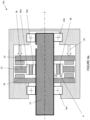
- Figure 1 shows a known design of brake 10 for an aircraft.
- a rotary shaft 12 extends into a housing 14 of the brake 12.
- the shaft 12 interfaces with the aircraft such that rotation of a component of the aircraft (e.g. a rotor, propeller etc. - not shown) also drives the shaft 12 for rotation.
- the shaft 12 has a shaft axis X.
- the shaft 12 is supported on a pair of bearings 16a,b that are mounted in the housing 14.
- a first brake pad 18 is located within the housing 14 and is held against rotation with respect to the housing 14.
- a second brake pad 20 is located within the housing 14 and is held against rotation with respect to the housing 14.
- the first and second brake pads 18,20 are ring-shaped and extend circumferentially around the shaft 12 (i.e. around the shaft axis X) and are generally coaxial with the shaft axis X and are radially spaced from the shaft 12. In other examples (not shown), the brake pads 18,20 do not extend around the full circumference of the shaft 12.
- the shaft has teeth or splines 12a along at least a portion of its outer surface within the housing 14.
- At least one of the brake pads 18,20 is configured to move axially within the housing 14, along the direction of the shaft axis X.
- the second brake pad 20 is arranged to move axially along axis X within the housing 14, and the first brake pad 18 is axially fixed within the housing 14.
- the first brake pad 18 may additionally or alternatively be axially movable along the axis X within the housing 14.
- the first and second brake pads 18,20 are arranged either side of a brake disk 22.
- a brake disk 22 is provided on the shaft 12. As shown in Figure 2 , the brake disk 22 has teeth 24 which engage with the teeth or splines 12a on the shaft 12, such that the brake disk 22 may move axially along the shaft 12 and such that rotation of the shaft 12 is transmitted to the brake disk 22 and, correspondingly, braking of the brake disk 22 will brake the shaft 12.
- the brake disk 22 is arranged axially between the first and second brake pads 18,20.
- the disk 22 can be axially fixed on shaft 12, i.e. such that the disk 22 does not slide along the shaft 12 under pressure from one of the brake pads 18,20.
- a component e.g. rotor, propeller etc.
- the component may be connected to the shaft 12 via a gearbox (not shown).
- the second brake pad 20 is pressed against the brake disk 22. Under this pressure, the brake disk 22 slides along the shaft 12 until it contacts the first brake pad 18.
- the brake disk 22 is then squeezed between the first and second brake pads 18,20 and, via friction, rotation of the brake disk 22 (and therefore rotation of both the shaft 12 and the component) is slowed.
- Rotation of the brake disk 22 while it is being squeezed by the brake pads 18,20 generates heat within the brake 10 via friction with the brake pads 18,20. This converts the kinetic energy of the brake disk 52 and shaft 12 into thermal energy in the brake 10.
- the second brake pad 20 may be moved by any conventional means, including a hydraulic actuator, a mechanical actuator, or an electrical actuator and the movement means are schematically depicted by arrow 23 in Figure 1 .
- a suitable mechanical actuator in some small helicopters there is a lever in the cockpit that pulls on a cable to apply one or both of the brake pads 18,20 to the disk 22.
- first brake pad 18 may alternatively or additionally move axially within the housing, then the first brake pad 18 too may be moved by any conventional means, including a hydraulic actuator, mechanical actuator, or an electrical actuator.
- the principle of braking operation is thereafter the same as before, i.e. the brake disk 22 is squeezed between the two brake pads 18,20 and this inhibits/slows rotation of the shaft 12.
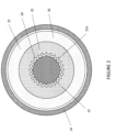
- brake disk 22 is shown in plan view in Figure 2 .
- This brake disk 22 is shown in situ, mounted on the shaft 12 and located within the housing 14.
- the inter-engagement of the teeth 24 of the brake disk 22 with the teeth or splines 12a of the shaft 12 ensure that the brake disk 22 and shaft 12 are connected together for rotation.
- the brake disk 22 remains connected to the shaft 12 via the teeth or splines at all points along the brake disk's 22 range of axial motion during the braking operation. That is, when the brake disk 22 slides along the shaft 12 under pressure from the second brake pad 20, the brake disk 22 remains connected for rotation with the shaft 12.
- the braking disk 22 has a braking surface 26 formed in a ring shape, where the ring shape is concentric with the shaft axis X. During braking, the brake pads 18,20 press against the braking surface 26 of the braking disk 22 on both sides of the braking disk 22.
- the brake disk 22 Radially inward from, and connected to, the braking surface 26, the brake disk 22 comprises a mounting portion 25.
- the teeth 24 of the braking disk are formed at a radially inner extent of the mounting portion 25, facing in towards the shaft 12.
- the braking surface 26 may be formed of any suitable material. Examples of suitable materials, include carbon/carbon, carbon/ceramic, and steel. Other suitable materials for the braking surface are known in the art.
- the braking surface 26 may be formed from the same material as the mounting portion 25 or from a different material.
- the mounting portion 25 may have a different axial thickness (measured along the shaft axis X, when mounted on the shaft 12) than the braking surface 26.
- the mounting portion 25 is thicker than the braking surface 26.
- the mounting portion 25 may have the same axial thickness as the braking portion 26 or may be thinner than the braking portion 26.
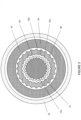
- FIG. 3 shows a cross-section of a brake disk 52 according to the present invention.
- This brake disk 52 is usable within the brake 10 described hereinabove and so like reference numerals will be used to describe like components.
- the method of operation of a brake 10 incorporating the present brake disk 52 is also mostly similar and so the following description will focus primarily on the differences.
- Figure 3 shows the brake disk 52 mounted on the shaft 12 and within the housing 14.
- the brake disk 52 has teeth or splines 54 that engage corresponding teeth or splines 12a of the shaft 12.
- the inter-engagement of the teeth (or splines) 54 of the brake disk 52 with the teeth or splines 12a of the shaft 12 ensure that the brake disk 52 and shaft 12 are connected together for rotation.
- the brake disk 52 has a braking surface 56 formed in a ring shape, mounted circumferentially around the shaft 12 and concentric with the shaft axis X. As before, during braking, the brake pads 18,20 press against the braking surface 56 of the braking disk 52 to brake rotation of the brake disk 52 and thereby brake rotation of the shaft 12.
- the fusible material section 58 extends circumferentially around the shaft axis X, such that the braking surface 56 is connected to the teeth 54 via the fusible material section 58.
- the material for the fusible material section 58 is selected such that it will melt, thermally decompose, or substantially weaken when its temperature rises above a given threshold temperature.
- the given threshold temperature may be considered a maximum operating temperature of the fusible material section 58.
- the material may, for example, be a eutectic material having a well-defined melting point and, in this example, the melting point is the maximum operating temperature.
- the maximum operating temperature of the fusible material section may be greater than 200°C and equal to or less than 1000°C. In other examples, the maximum operating temperature may be in the range of 450°C to 700°C, or in the range 625°C to 675°C. In one example, the maximum operating temperature may be 645°C (i.e. this may be the melting temperature of the material of the fusible material section). If the temperature within the brake disk 52 rises above the threshold (e.g. the melting point of the eutectic material), as a result of heat of friction between the brake pads 18,20 and the braking surface 56, then the fusible material section 58 will melt (or thermally decompose etc.). This causes the braking surface 56 to mechanically disconnect from the teeth 54 and therefore disconnect from the shaft 12.
- the threshold e.g. the melting point of the eutectic material
- the braking surface 56 also has a maximum operating temperature (i.e. a temperature at which the material of the braking surface will melt or thermally decompose) and this is higher than the maximum operating temperature of the fusible material section 58.
- a maximum operating temperature i.e. a temperature at which the material of the braking surface will melt or thermally decompose
- the maximum operating temperature of the braking surface will be 1450°C.
- the fusible material section 58 will melt (or thermally decompose etc.) at the predetermined threshold temperature.
- the braking surface 56 now disconnected from the shaft 12, will be rapidly brought to a stop by friction with the brake pads 18, 20 without producing much more heat (e.g. the braking surface 56 has low inertia and so, once disconnected from the shaft 12, the brake pads 18, 20 only need to absorb a small amount of remaining rotational energy from the braking surface 56). In this situation, the shaft 12 will continue to spin freely.
- the brake 10 temperature will not rise too high. This may mitigate the risk of a fire or thermal damage as a result of excessive heating in the brake 10.
- the predetermined threshold may be selected via choice of material for the fusible material section 58, and may be selected to be below e.g. a flash point of hydraulic fluid used adjacent and/or within the brake 10. As such, in the event that the brake 10 is applied while the engine is still running, the fusible material section 58 melts and the brake 10 will not become so hot as to be a fire risk. The melted fusible material may be trapped inside the housing 14 in order keep the external surface of the brake 10 below a fire ignition temperature.
- the material for the fusible material section 58 may be selected such that its maximum operating temperature is above the worst case of expected normal operation of the brake 10. This is so the brake 10 will continue to function under normal operations, but will avoid overheating under abnormal operations.
- One commonly used aircraft fuel has a self-ignition temperature of 206°C. Therefore, keeping the outer temperature of the brake housing 14 below 206°C, in both normal and abnormal operations, may avoid the ignition of fuel contacting the brake 10, e.g. in case of a fuel leak.
- the fusible material rises above its maximum operating temperature, some or all of it may contact the inside of the brake housing 14 and cause the temperature of the brake housing 14 to rise.
- the amount of temperature rise will be partly a function of the temperature of the fusible material contacting the housing 14 and also a function of, for example, the amount of fusible material contacting the housing 14, and the thickness and material of the housing 14 itself.
- the maximum operating temperature of the fusible material e.g. 450°C
- the maximum temperature of the fusible material may be higher than the maximum temperature that will occurs at the outside of the brake housing 14 in the event of abnormal operation (e.g. 206°C) by proper selection of the aforesaid parameters.
- Figure 4A shows a cross-section of a brake 10 incorporating the brake disk 52 according to the present invention.
- the fusible material section 58 forms the connection between the teeth 52 of the brake disk 52 and the braking surface 56.
- the brake disk 52 has a generally annular mounting portion 55a,b that extends around the shaft 12. Teeth 54 are formed in the mounting portion 55a,b.
- the fusible material section 58 is connected at a radially inner side to a first part of the mounting portion 55a and at a radially outer side to a second part of the mounting portion 55b. The radially outer part of the mounting portion 55b then connects to the braking surface 56.
- the teeth 54 may be formed directly in the fusible material section 58, and the fusible material may connect directly to the braking surface 56, in which case there no mounting portion would be required.
- the brake disk 52 may have a mounting portion 55a radially inward from and connected directly to the fusible material section 58, and the braking surface 58 may be radially outward from and connected directly to the fusible material section 55b. That is, the second portion of the mounting portion 55b may be omitted.
- the disclosed arrangements keep the fusible material section 58 in close proximity and thermal contact with the region where heat is generated during braking, i.e. the braking surface 58 and brake pads 18,20. As such, the fusible material section will melt quickly when excess heat is generated in the brake 10 during abnormal operation.
- Figure 4B shows a cross-section of the same brake 10 of Figure 4A after the fusible material section 58 has been heated above the predetermined threshold, such that the braking surface 56 has disconnected from the teeth 54. That is, after the fusible material has melted, thermally decomposed, or otherwise broken due to weakening at high temperature.
- the brake pads 18,20 have been moved apart from the braking surface 56 and the braking surface sits loose within the housing 14, disconnected from the teeth 54 and from the shaft 12.
- the fusible material section 58 may take a variety of shapes.
- the fusible material section 58 is substantially ring-shaped and has a zig-zag profile at a radially inner side 60 of the ring-shape (i.e. towards the teeth 54 and mounting portion 55) and has a zig-zag profile at a radially outer side 62 of the ring shape (i.e. towards the braking surface 56).
- the zig-zag profiles assist the transmission of torque between the shaft 12 to the braking surface 58, i.e. by preventing slip between the various components of the braking disk 52.
- shape for the profile at the outer side 62 and at the inner side 60 are envisaged, including splines, teeth, or a wavy shape.
- any non-circular shape for the profile at the outer side 62 and/or inner side 60 may suffice to assist torque transmission between parts of the brake disk 52, i.e. to assist torque transmission between the shaft 12 and the braking surface 56.
- Specific shapes may be chosen on the basis of ease of manufacturing and/or effectiveness of torque-transfer.
- the fusible material section 58 has a minimum radial thickness A.
- a gap B is defined as the radial clearance between the outermost radial side 52a of the brake disk 52 and an inner wall 14a of the housing 14, when the brake disk 52 is intact (i.e. when the fusible material section 58 is intact and connects the teeth 54 to the braking surface 56).
- Thickness A is greater than gap B, i.e. A>B. That is, the gap B between the radially outermost extent 52a of the brake disk 52 and the inner wall 14a of the housing 14 is smaller than the minimum radial thickness A of the fusible material.
- the braking surface 56 (and the outer portion 55b of the mounting portion that is connected to the braking surface 56) will be free to move under gravity or vibration within the housing 14. If the braking surface 26 moves transverse to the shaft axis X, it will not come into contact with the teeth 54 or the shaft 12 because A>B. That is, the radially outermost surface 52a of the braking disk 52 will come into abutment with the inner surface 14a of the housing 14 before a radially inward part can contact either the shaft 12 or the mounting portion 55a. Thus, the disconnected part of the brake disk 52 will not be "bounced around" within the housing 14 by coming into contact with the still-spinning shaft 12.
- A is sufficiently greater than B such that the disconnected portion of the brake disk 52 may additionally be tilted relative to the shaft axis X and still not come into contact with the shaft 12.
- the baking surface 56 is thin it is possible that tilting movement of the disconnected portion of the brake disk 52 relative to the shaft axis X could cause contact with parts still in rotation (e.g. the shaft 12 or the mounting portion 55a). To avoid this contact, the backlash between pads 18 and 20 in the brake-released position can be reduced. In this situation, contact between the (tilted) braking surface 56 and one or other of the brake pads 18,20 may limit the tilting movement of the disconnected braking surface 56.
- the minimum radial thickness A of the fusible material section 58 may be enlarged to compensate for possible tilting of the braking surface after the fusible material section 58 no longer connects between the braking surface 58 and the shaft 12
- Figure 6 shows a perspective view of the brake disk 52 with a portion of the braking surface 58 removed in order to show further features of the fusible material section 58.
- This example brake disk 52 does not have an outer mounting portion 55b, and instead the fusible material section 58 directly contacts the braking surface 56.
- the fusible material section 58 has a spline 68 extending circumferentially around its outer side 62 at an axial location within the axial thickness of the brake disk 52.
- the spline 68 engages with a corresponding circumferential groove 66 on a radially inner side of the braking surface 56.
- This spline 68 may assist in transmitting axially directed forces (e.g. forces axially along the direction of the shaft axis X) within the brake disk 52. This mechanical engagement may therefore assist in holding together the brake disk 52 during normal operation.
- Figure 7A shows a cross-section through the brake disk 52 shown in Figure 6 .
- the fusible material section 58 has a second spline 70 extending circumferentially around its inner side 60 at an axial location within the axial thickness of the brake disk 52.
- the second spline 70 engages with a corresponding circumferential groove 72 on a radially outer side of the mounting portion 55a. This mechanical engagement may therefore assist in holding together the brake disk 52 during normal use.
- Figure 7B shows an alternative design of fusible material section 58 in which the fusible material has an I-shaped cross-section when viewed in the plane of the brake disk 52.
- the braking portion 56 and the mounting portion 55a both extend in-between the top and bottom radially extending portions of the I-shaped cross-section, such that the fusible material section 58 is held securely within the brake disk 52.
- a pair of open grooves may be machined on axially front and rear surfaces of the braking surface 56 and of the mounting portion 55a, and the fusible material may fill these open grooves to provide axial strength to the brake disk 52.
- the material for the fusible material section 58 is chosen to have a lower melting temperature (or thermal decomposition temperature etc.) than the braking surface 56 and the mounting portion 55a,b.
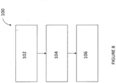
- a method 100 of making a braking disk (52) is shown in Figure 8 .
- the method includes, at step 102, arranging two components such that an annular gap is defined therebetween.
- molten fusible material is poured into the annular gap to fill the gap.
- the molten material is cooled so that it solidifies to form the fusible material section 58.
- the fusible material section 58 is cast between the two components.
- the two components may be two portions 55a and 55b of the mounting portion may be placed concentrically with one another with the annular gap defined therebetween.
- the annular gap is defined between the braking surface 58 and the (single-part) mounting portion 55a,b.
- a sacrificial component is provided radially inward of the braking surface 58, e.g. to mimic the outer surface of the shaft 12, and the annular gap is formed between the braking surface and sacrificial component.
- the molten fusible material may be poured into the gap and, after the material has solidified, the sacrificial portion may be removed.
- the brake disk 52 may be formed to be integral with the shaft 12.
- a first of the two components is the braking surface 56 and a second of the two components is the shaft 12.
- one or both of the components may have a toothed or zig-zag profile such that a toothed or zig-zag profile is formed in the resultant fusible material section.
- the brake disk 52 of the present invention may also be used in other brake designs.
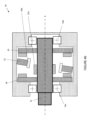
- Figure 9 shows an example brake 10a in which both brake pads 18,20 are movable.
- a first means 23' e.g. an actuator
- a second means 23 is provided for moving the second brake pad 20 within the brake 10a.
- the brake pads 18,20 are thus both movable and may be moved so as to squeeze the braking surface 56 therebetween to effect braking.
- the brake disk 52a is either axially fixed with respect to the shaft 12 or formed integrally with the shaft 12. In the example shown in Figure 9 , there is a mounting portion 55c that is axially fixed relative to the shaft 12.
- the fusible material section 58 sits radially outward of the axially fixed mounting portion, and a second portion 55b of the mounting portion sits radially outward of the fusible material section 58.
- the braking surface is connected to a radially outer side of the second portion 55b.
- the brake disk 52a of Figure 9 may have a braking surface 56 and fusible material section 58 that are identical to the braking surface 56 and fusible material section 58 of the braking disk depicted in e.g. Figure 3 or 4A .
- the other features of the brake 10a of Figure 9 may otherwise be identical to the brake 10 described hereinabove, e.g. in relation to Figure 4 .
- a multi-disk brake where multiple brake disks are disposed on a shaft (e.g. shaft 12) and axially movable along the shaft. Between and around the multiple brake disks there are multiple brake pads. To actuate the brake, at least an endmost brake pad is driven axially to compress the multiple brake disks between the brake pads. Any or all of the brake disks in this design may be a brake disk 52 according to the present invention.
Landscapes
- Engineering & Computer Science (AREA)
- General Engineering & Computer Science (AREA)
- Mechanical Engineering (AREA)
- Aviation & Aerospace Engineering (AREA)
- Braking Arrangements (AREA)
Claims (15)
- Disque de frein (52, 52a), le disque de frein définissant une forme annulaire ayant un côté radialement interne et un côté radialement externe ; le disque de frein (52) comprenant :une surface de freinage radialement externe (56), la surface de freinage ayant une température de fonctionnement maximale ; etle disque de frein étant caractérisé en ce qu'il comprend :une section de matériau fusible (58) radialement vers l'intérieur depuis et reliée à la surface de freinage, le matériau fusible ayant une température de fonctionnement maximale, la section de matériau fusible pour transmettre un couple entre la surface de freinage et un arbre (12) tandis qu'une température de la section de matériau fusible est inférieure à la température de fonctionnement maximale de la section du matériau fusible ;dans lequel la température de fonctionnement maximale de la surface de freinage est supérieure à la température de fonctionnement maximale de la section de matériau fusible ; etdans lequel lorsque la température de la section de matériau fusible s'élève au-dessus de la température de fonctionnement maximale de la section de matériau fusible, la section de matériau fusible est configurée pour ne plus transmettre de couple entre la surface de freinage et l'arbre.
- Disque de frein selon la revendication 1, dans lequel la section en matériau fusible comprend une cannelure (68) s'étendant circonférentiellement autour d'un côté radialement externe de la section en matériau fusible ; et/ou dans lequel la section de matériau fusible comprend une cannelure (70) s'étendant circonférentiellement autour d'un côté radialement interne de la section de matériau fusible.
- Disque de frein selon une quelconque revendication précédente, dans lequel la section de matériau fusible a un profil non circulaire au niveau d'une surface radialement externe (62) ; et/ou dans lequel la section de matériau fusible a un profil non circulaire au niveau d'une surface radialement interne (60).
- Disque de frein selon la revendication 3, dans lequel le ou chaque profil non circulaire comprend l'un parmi : un profil externe denté, un profil externe cannelé et un profil externe en zigzag.
- Disque de frein selon une quelconque revendication précédente, dans lequel la section de matériau fusible (58) est réalisée à partir d'un matériau eutectique.
- Disque de frein selon une quelconque revendication précédente, comprenant en outre une partie de montage annulaire (55a,b), dans lequel une ou plusieurs dents (54) sont formées dans une surface radialement la plus interne de la partie de montage.
- Disque de frein selon la revendication 6, dans lequel la partie de montage annulaire comprend une première partie (55a) et une seconde partie (55b), dans lequel la section de matériau fusible (58) est formée entre les première et seconde parties de la partie de montage, de sorte que la section de matériau fusible est reliée à la surface de freinage via la seconde partie de la partie de montage.
- Disque de frein selon la revendication 6 ou 7, dans lequel la portion de montage a une première épaisseur axiale, dans lequel le matériau fusible a une deuxième épaisseur axiale, et dans lequel la surface de freinage a une troisième épaisseur axiale, dans lequel la troisième épaisseur axiale est inférieure aux première et deuxième épaisseurs axiales.
- Disque de frein selon l'une quelconque des revendications 1 à 5, dans lequel une ou plusieurs dents (54) sont formées au niveau d'une surface radialement la plus interne de la section de matériau fusible (58).
- Disque de frein selon une quelconque revendication précédente, dans lequel la température de fonctionnement maximale de la section de matériau fusible (58) est comprise dans la plage de 200 °C à 1 000 °C ; et/ou dans lequel la section de matériau fusible est configurée pour fondre, se décomposer thermiquement ou s'affaiblir sensiblement lorsqu'elle est au-dessus de sa température de fonctionnement maximale, de manière à ne plus transmettre de couple à la surface de freinage (56).
- Frein (10, 10a) pour un aéronef comprenant :un carter (14) ;un arbre (12) définissant un axe (X) et s'étendant dans le carter et ayant des dents ou des cannelures (12a) ;une première plaquette de frein (18) et une seconde plaquette de frein (20) ; etle disque de frein (52, 52a) selon une quelconque revendication précédente agencé sur ou formé d'un seul tenant avec l'arbre (12) et situé axialement entre les première et seconde plaquettes de frein (18, 20) ;dans lequel le frein (10) est configuré pour déplacer au moins l'une des plaquettes de frein (18, 20) pour s'appuyer contre la surface de freinage du disque de frein (52) pour résister à la rotation du disque de frein par frottement et ainsi résister à la rotation de l'arbre (12).
- Frein selon la revendication 11, dans lequel la section de matériau fusible a une épaisseur minimale (A) dans la direction radiale, et dans lequel un espace ayant une longueur (B) est défini entre une surface radialement la plus externe (52a) du disque de freinage et une surface interne (14a) du carter (14), dans lequel l'épaisseur minimale (A) est supérieure à la longueur de l'espace (B).
- Frein selon la revendication 11 ou 12, comprenant en outre un ou plusieurs paliers (16a,b) montés sur l'arbre (12) et sur le carter (14) pour supporter l'arbre en rotation à l'intérieur du carter, et/ou comprenant en outre un actionneur (24) pour déplacer l'une des première ou seconde plaquettes de frein (18, 20) axialement à l'intérieur du carter (14) le long de la direction de l'axe de l'arbre (X).
- Procédé de fabrication d'un disque de frein (52), le procédé comprenant :
la coulée d'un matériau fusible fondu, le procédé étant caractérisé par la coulée du matériau fusible fondu dans un espace annulaire entre deux composants, dans lequel les deux composants sont soit :1) des première et seconde parties de montage (55a, 55b) du disque de frein, ou2) une partie de montage (55a) et une surface de freinage (56) du disque de frein ; ou3) une surface de freinage (56) du disque de frein et un composant sacrificiel ; ou4) une surface de freinage du frein à disque et un arbre (12) ; et le procédé comprenant en outre la solidification du matériau fusible pour former une section de matériau fusible (58) entre les premier et second composants. - Procédé selon la revendication 14, comprenant en outre l'usinage d'une rainure annulaire dans l'un ou les deux composants, de sorte que lorsque le matériau fusible fondu est versé dans l'espace annulaire, le matériau fusible fondu remplit la ou les rainures.
Priority Applications (5)
| Application Number | Priority Date | Filing Date | Title |
|---|---|---|---|
| EP21290020.3A EP4074596B1 (fr) | 2021-04-12 | 2021-04-12 | Disque de frein avec fusible thermique intégré et procédé de fabrication d'un disque de frein avec fusible thermique intégré |
| CA3149756A CA3149756A1 (fr) | 2021-04-12 | 2022-02-21 | Disque de frein et frein comprenant un fusible thermique integre |
| BR102022005874-1A BR102022005874A2 (pt) | 2021-04-12 | 2022-03-28 | Disco de freio, freio para uma aeronave, e, método para fabricar um disco de freio |
| US17/706,812 US12000444B2 (en) | 2021-04-12 | 2022-03-29 | Brake disk and brake with integral thermal fuse |
| CN202210380026.8A CN115199672A (zh) | 2021-04-12 | 2022-04-12 | 带集成热熔断器的制动盘和制动器 |
Applications Claiming Priority (1)
| Application Number | Priority Date | Filing Date | Title |
|---|---|---|---|
| EP21290020.3A EP4074596B1 (fr) | 2021-04-12 | 2021-04-12 | Disque de frein avec fusible thermique intégré et procédé de fabrication d'un disque de frein avec fusible thermique intégré |
Publications (2)
| Publication Number | Publication Date |
|---|---|
| EP4074596A1 EP4074596A1 (fr) | 2022-10-19 |
| EP4074596B1 true EP4074596B1 (fr) | 2023-05-31 |
Family
ID=76695661
Family Applications (1)
| Application Number | Title | Priority Date | Filing Date |
|---|---|---|---|
| EP21290020.3A Active EP4074596B1 (fr) | 2021-04-12 | 2021-04-12 | Disque de frein avec fusible thermique intégré et procédé de fabrication d'un disque de frein avec fusible thermique intégré |
Country Status (5)
| Country | Link |
|---|---|
| US (1) | US12000444B2 (fr) |
| EP (1) | EP4074596B1 (fr) |
| CN (1) | CN115199672A (fr) |
| BR (1) | BR102022005874A2 (fr) |
| CA (1) | CA3149756A1 (fr) |
Families Citing this family (3)
| Publication number | Priority date | Publication date | Assignee | Title |
|---|---|---|---|---|
| EP4148293B1 (fr) * | 2021-09-10 | 2024-12-25 | Ratier-Figeac SAS | Frein d'avion avec fusible thermique et méthode de fonctionnement |
| EP4219973B1 (fr) * | 2022-01-27 | 2024-12-25 | Ratier-Figeac SAS | Ensemble frein doté d'un fusible thermique |
| CN117329244B (zh) * | 2023-12-01 | 2024-02-02 | 山西强力矿用设备制造有限公司 | 液压湿式制动集成结构 |
Family Cites Families (19)
| Publication number | Priority date | Publication date | Assignee | Title |
|---|---|---|---|---|
| US2224440A (en) * | 1938-05-28 | 1940-12-10 | Spicer Mfg Corp | Safety clutch |
| US2655015A (en) * | 1947-01-30 | 1953-10-13 | Linder Francois | Thermally releasable torque limiting clutch |
| US2825437A (en) * | 1954-09-07 | 1958-03-04 | Koren Res & Engineering Compan | Coupling apparatus |
| US2907426A (en) * | 1955-03-23 | 1959-10-06 | Gen Motors Corp | Coupling for transmitting torques |
| GB798952A (en) * | 1955-10-07 | 1958-07-30 | Rotol Ltd | Improvements in or relating to parking brakes particularly for aircraft turbo-propeller propulsion units |
| US3675444A (en) * | 1970-11-03 | 1972-07-11 | Gen Electric | High speed shaft disconnect utilizing a fusible element |
| US4241818A (en) * | 1978-10-30 | 1980-12-30 | Facet Enterprises, Inc. | Lightweight electromagnetic clutch with shock absorber |
| US4763762A (en) * | 1987-11-10 | 1988-08-16 | The United States Of America As Represented By The United States National Aeronautics And Space Administration | Preloaded brake disc |
| US5062503A (en) | 1990-09-19 | 1991-11-05 | Allied-Signal Inc. | Ablative brake bushing for axle thermal protection |
| JP2575892Y2 (ja) * | 1992-09-02 | 1998-07-02 | サンデン株式会社 | プーリー直結型コンプレッサー |
| US5613578A (en) * | 1993-12-21 | 1997-03-25 | Aircraft Braking Systems Corporation | Phase change brake disks |
| JPH08319945A (ja) * | 1995-05-25 | 1996-12-03 | Zexel Corp | クラッチレス圧縮機 |
| US5862892A (en) * | 1996-04-16 | 1999-01-26 | Hayes Lemmerz International Inc. | Composite rotor for caliper disc brakes |
| JP3736838B2 (ja) * | 2000-11-30 | 2006-01-18 | 日立粉末冶金株式会社 | メカニカルヒューズおよびその製造方法 |
| US8210232B2 (en) * | 2007-09-20 | 2012-07-03 | GM Global Technology Operations LLC | Lightweight brake rotor and components with composite materials |
| US8517698B2 (en) * | 2011-03-17 | 2013-08-27 | Delphi Technologies, Inc. | Air conditioning compressor over-torque protector |
| FR2985294B1 (fr) * | 2011-12-29 | 2014-02-14 | Ratier Figeac Soc | Dispositif a engagement automatique de freinage d'un arbre rotatif monte rotatif sur un chassis |
| EP3650340B1 (fr) | 2018-11-12 | 2021-10-20 | Ratier-Figeac SAS | Dispositif de gestion de surchauffe de frein de rotor |
| EP4148293B1 (fr) * | 2021-09-10 | 2024-12-25 | Ratier-Figeac SAS | Frein d'avion avec fusible thermique et méthode de fonctionnement |
-
2021
- 2021-04-12 EP EP21290020.3A patent/EP4074596B1/fr active Active
-
2022
- 2022-02-21 CA CA3149756A patent/CA3149756A1/fr active Pending
- 2022-03-28 BR BR102022005874-1A patent/BR102022005874A2/pt unknown
- 2022-03-29 US US17/706,812 patent/US12000444B2/en active Active
- 2022-04-12 CN CN202210380026.8A patent/CN115199672A/zh active Pending
Also Published As
| Publication number | Publication date |
|---|---|
| EP4074596A1 (fr) | 2022-10-19 |
| US12000444B2 (en) | 2024-06-04 |
| US20220325761A1 (en) | 2022-10-13 |
| CN115199672A (zh) | 2022-10-18 |
| CA3149756A1 (fr) | 2022-10-12 |
| BR102022005874A2 (pt) | 2022-10-18 |
Similar Documents
| Publication | Publication Date | Title |
|---|---|---|
| US12000444B2 (en) | Brake disk and brake with integral thermal fuse | |
| EP2668414B1 (fr) | Disque pour freins à disque | |
| KR101336369B1 (ko) | 두 개의 클러치 팩을 구비하여 이중으로 작용하는 클러치,그리고 상기 클러치를 조정하기 위한 방법 | |
| US5540305A (en) | Multi-disc brake | |
| GB2285104A (en) | Phase change brake disks | |
| EP1602845B1 (fr) | Mécanisme de desacoupplement | |
| US6364772B1 (en) | Disconnect for high-speed rotating shafts | |
| JPS61248926A (ja) | 航空機などの車輪のための耐熱性デイスクブレ−キ | |
| EP4148293B1 (fr) | Frein d'avion avec fusible thermique et méthode de fonctionnement | |
| US3892293A (en) | Disc brakes | |
| EP3717317B1 (fr) | Piston d'un étrier de freinage, étrier de freinage et -procédé de manufacture | |
| US12416340B2 (en) | Brake assembly with thermal fuse | |
| US4287975A (en) | Clutch with fusible material as protective element | |
| EP4253784B1 (fr) | Ensemble roue et frein | |
| EP3650340B1 (fr) | Dispositif de gestion de surchauffe de frein de rotor | |
| EP2126398A1 (fr) | Freinage | |
| EP4299942B1 (fr) | Trajet de pression de piston à sécurité intégrée | |
| EP4289689B1 (fr) | Isolateur de frein d'avion multicouche | |
| EP4027033B1 (fr) | Ensemble roue et frein avec arrêt mécanique | |
| EP2711291A1 (fr) | Frein de rotor monté sur un arbre | |
| EP3539834B1 (fr) | Bouclier thermique de frein d'aéronef | |
| US12522064B2 (en) | Drive shaft assembly for driven accessory devices | |
| KR20230099662A (ko) | 브레이크 드럼, 브레이크 드럼을 생산하는 방법 및 드럼 브레이크 조립체 |
Legal Events
| Date | Code | Title | Description |
|---|---|---|---|
| PUAI | Public reference made under article 153(3) epc to a published international application that has entered the european phase |
Free format text: ORIGINAL CODE: 0009012 |
|
| STAA | Information on the status of an ep patent application or granted ep patent |
Free format text: STATUS: REQUEST FOR EXAMINATION WAS MADE |
|
| 17P | Request for examination filed |
Effective date: 20211027 |
|
| AK | Designated contracting states |
Kind code of ref document: A1 Designated state(s): AL AT BE BG CH CY CZ DE DK EE ES FI FR GB GR HR HU IE IS IT LI LT LU LV MC MK MT NL NO PL PT RO RS SE SI SK SM TR |
|
| REG | Reference to a national code |
Ref country code: DE Ref legal event code: R079 Ref document number: 602021002561 Country of ref document: DE Free format text: PREVIOUS MAIN CLASS: B64C0027120000 Ipc: F16D0065120000 |
|
| GRAP | Despatch of communication of intention to grant a patent |
Free format text: ORIGINAL CODE: EPIDOSNIGR1 |
|
| STAA | Information on the status of an ep patent application or granted ep patent |
Free format text: STATUS: GRANT OF PATENT IS INTENDED |
|
| RIC1 | Information provided on ipc code assigned before grant |
Ipc: F16D 65/02 20060101ALN20221013BHEP Ipc: F16D 55/00 20060101ALN20221013BHEP Ipc: F16D 55/32 20060101ALI20221013BHEP Ipc: F16D 55/30 20060101ALI20221013BHEP Ipc: B64D 35/00 20060101ALI20221013BHEP Ipc: B64C 27/12 20060101ALI20221013BHEP Ipc: F16D 65/12 20060101AFI20221013BHEP |
|
| RIC1 | Information provided on ipc code assigned before grant |
Ipc: F16D 65/02 20060101ALN20221019BHEP Ipc: F16D 55/00 20060101ALN20221019BHEP Ipc: F16D 55/32 20060101ALI20221019BHEP Ipc: F16D 55/30 20060101ALI20221019BHEP Ipc: B64D 35/00 20060101ALI20221019BHEP Ipc: B64C 27/12 20060101ALI20221019BHEP Ipc: F16D 65/12 20060101AFI20221019BHEP |
|
| INTG | Intention to grant announced |
Effective date: 20221115 |
|
| GRAS | Grant fee paid |
Free format text: ORIGINAL CODE: EPIDOSNIGR3 |
|
| GRAA | (expected) grant |
Free format text: ORIGINAL CODE: 0009210 |
|
| STAA | Information on the status of an ep patent application or granted ep patent |
Free format text: STATUS: THE PATENT HAS BEEN GRANTED |
|
| AK | Designated contracting states |
Kind code of ref document: B1 Designated state(s): AL AT BE BG CH CY CZ DE DK EE ES FI FR GB GR HR HU IE IS IT LI LT LU LV MC MK MT NL NO PL PT RO RS SE SI SK SM TR |
|
| REG | Reference to a national code |
Ref country code: GB Ref legal event code: FG4D Ref country code: CH Ref legal event code: EP |
|
| REG | Reference to a national code |
Ref country code: DE Ref legal event code: R096 Ref document number: 602021002561 Country of ref document: DE |
|
| REG | Reference to a national code |
Ref country code: AT Ref legal event code: REF Ref document number: 1571093 Country of ref document: AT Kind code of ref document: T Effective date: 20230615 |
|
| REG | Reference to a national code |
Ref country code: IE Ref legal event code: FG4D |
|
| REG | Reference to a national code |
Ref country code: LT Ref legal event code: MG9D |
|
| REG | Reference to a national code |
Ref country code: NL Ref legal event code: MP Effective date: 20230531 |
|
| REG | Reference to a national code |
Ref country code: AT Ref legal event code: MK05 Ref document number: 1571093 Country of ref document: AT Kind code of ref document: T Effective date: 20230531 |
|
| PG25 | Lapsed in a contracting state [announced via postgrant information from national office to epo] |
Ref country code: SE Free format text: LAPSE BECAUSE OF FAILURE TO SUBMIT A TRANSLATION OF THE DESCRIPTION OR TO PAY THE FEE WITHIN THE PRESCRIBED TIME-LIMIT Effective date: 20230531 Ref country code: NO Free format text: LAPSE BECAUSE OF FAILURE TO SUBMIT A TRANSLATION OF THE DESCRIPTION OR TO PAY THE FEE WITHIN THE PRESCRIBED TIME-LIMIT Effective date: 20230831 Ref country code: ES Free format text: LAPSE BECAUSE OF FAILURE TO SUBMIT A TRANSLATION OF THE DESCRIPTION OR TO PAY THE FEE WITHIN THE PRESCRIBED TIME-LIMIT Effective date: 20230531 Ref country code: AT Free format text: LAPSE BECAUSE OF FAILURE TO SUBMIT A TRANSLATION OF THE DESCRIPTION OR TO PAY THE FEE WITHIN THE PRESCRIBED TIME-LIMIT Effective date: 20230531 |
|
| PG25 | Lapsed in a contracting state [announced via postgrant information from national office to epo] |
Ref country code: RS Free format text: LAPSE BECAUSE OF FAILURE TO SUBMIT A TRANSLATION OF THE DESCRIPTION OR TO PAY THE FEE WITHIN THE PRESCRIBED TIME-LIMIT Effective date: 20230531 Ref country code: PL Free format text: LAPSE BECAUSE OF FAILURE TO SUBMIT A TRANSLATION OF THE DESCRIPTION OR TO PAY THE FEE WITHIN THE PRESCRIBED TIME-LIMIT Effective date: 20230531 Ref country code: NL Free format text: LAPSE BECAUSE OF FAILURE TO SUBMIT A TRANSLATION OF THE DESCRIPTION OR TO PAY THE FEE WITHIN THE PRESCRIBED TIME-LIMIT Effective date: 20230531 Ref country code: LV Free format text: LAPSE BECAUSE OF FAILURE TO SUBMIT A TRANSLATION OF THE DESCRIPTION OR TO PAY THE FEE WITHIN THE PRESCRIBED TIME-LIMIT Effective date: 20230531 Ref country code: LT Free format text: LAPSE BECAUSE OF FAILURE TO SUBMIT A TRANSLATION OF THE DESCRIPTION OR TO PAY THE FEE WITHIN THE PRESCRIBED TIME-LIMIT Effective date: 20230531 Ref country code: IS Free format text: LAPSE BECAUSE OF FAILURE TO SUBMIT A TRANSLATION OF THE DESCRIPTION OR TO PAY THE FEE WITHIN THE PRESCRIBED TIME-LIMIT Effective date: 20230930 Ref country code: HR Free format text: LAPSE BECAUSE OF FAILURE TO SUBMIT A TRANSLATION OF THE DESCRIPTION OR TO PAY THE FEE WITHIN THE PRESCRIBED TIME-LIMIT Effective date: 20230531 Ref country code: GR Free format text: LAPSE BECAUSE OF FAILURE TO SUBMIT A TRANSLATION OF THE DESCRIPTION OR TO PAY THE FEE WITHIN THE PRESCRIBED TIME-LIMIT Effective date: 20230901 |
|
| PG25 | Lapsed in a contracting state [announced via postgrant information from national office to epo] |
Ref country code: FI Free format text: LAPSE BECAUSE OF FAILURE TO SUBMIT A TRANSLATION OF THE DESCRIPTION OR TO PAY THE FEE WITHIN THE PRESCRIBED TIME-LIMIT Effective date: 20230531 |
|
| PG25 | Lapsed in a contracting state [announced via postgrant information from national office to epo] |
Ref country code: SK Free format text: LAPSE BECAUSE OF FAILURE TO SUBMIT A TRANSLATION OF THE DESCRIPTION OR TO PAY THE FEE WITHIN THE PRESCRIBED TIME-LIMIT Effective date: 20230531 |
|
| PG25 | Lapsed in a contracting state [announced via postgrant information from national office to epo] |
Ref country code: SM Free format text: LAPSE BECAUSE OF FAILURE TO SUBMIT A TRANSLATION OF THE DESCRIPTION OR TO PAY THE FEE WITHIN THE PRESCRIBED TIME-LIMIT Effective date: 20230531 Ref country code: SK Free format text: LAPSE BECAUSE OF FAILURE TO SUBMIT A TRANSLATION OF THE DESCRIPTION OR TO PAY THE FEE WITHIN THE PRESCRIBED TIME-LIMIT Effective date: 20230531 Ref country code: RO Free format text: LAPSE BECAUSE OF FAILURE TO SUBMIT A TRANSLATION OF THE DESCRIPTION OR TO PAY THE FEE WITHIN THE PRESCRIBED TIME-LIMIT Effective date: 20230531 Ref country code: PT Free format text: LAPSE BECAUSE OF FAILURE TO SUBMIT A TRANSLATION OF THE DESCRIPTION OR TO PAY THE FEE WITHIN THE PRESCRIBED TIME-LIMIT Effective date: 20231002 Ref country code: EE Free format text: LAPSE BECAUSE OF FAILURE TO SUBMIT A TRANSLATION OF THE DESCRIPTION OR TO PAY THE FEE WITHIN THE PRESCRIBED TIME-LIMIT Effective date: 20230531 Ref country code: DK Free format text: LAPSE BECAUSE OF FAILURE TO SUBMIT A TRANSLATION OF THE DESCRIPTION OR TO PAY THE FEE WITHIN THE PRESCRIBED TIME-LIMIT Effective date: 20230531 Ref country code: CZ Free format text: LAPSE BECAUSE OF FAILURE TO SUBMIT A TRANSLATION OF THE DESCRIPTION OR TO PAY THE FEE WITHIN THE PRESCRIBED TIME-LIMIT Effective date: 20230531 |
|
| REG | Reference to a national code |
Ref country code: DE Ref legal event code: R097 Ref document number: 602021002561 Country of ref document: DE |
|
| PLBE | No opposition filed within time limit |
Free format text: ORIGINAL CODE: 0009261 |
|
| STAA | Information on the status of an ep patent application or granted ep patent |
Free format text: STATUS: NO OPPOSITION FILED WITHIN TIME LIMIT |
|
| PG25 | Lapsed in a contracting state [announced via postgrant information from national office to epo] |
Ref country code: SI Free format text: LAPSE BECAUSE OF FAILURE TO SUBMIT A TRANSLATION OF THE DESCRIPTION OR TO PAY THE FEE WITHIN THE PRESCRIBED TIME-LIMIT Effective date: 20230531 |
|
| 26N | No opposition filed |
Effective date: 20240301 |
|
| PG25 | Lapsed in a contracting state [announced via postgrant information from national office to epo] |
Ref country code: SI Free format text: LAPSE BECAUSE OF FAILURE TO SUBMIT A TRANSLATION OF THE DESCRIPTION OR TO PAY THE FEE WITHIN THE PRESCRIBED TIME-LIMIT Effective date: 20230531 Ref country code: IT Free format text: LAPSE BECAUSE OF FAILURE TO SUBMIT A TRANSLATION OF THE DESCRIPTION OR TO PAY THE FEE WITHIN THE PRESCRIBED TIME-LIMIT Effective date: 20230531 |
|
| REG | Reference to a national code |
Ref country code: DE Ref legal event code: R119 Ref document number: 602021002561 Country of ref document: DE |
|
| PG25 | Lapsed in a contracting state [announced via postgrant information from national office to epo] |
Ref country code: BG Free format text: LAPSE BECAUSE OF FAILURE TO SUBMIT A TRANSLATION OF THE DESCRIPTION OR TO PAY THE FEE WITHIN THE PRESCRIBED TIME-LIMIT Effective date: 20230531 |
|
| PG25 | Lapsed in a contracting state [announced via postgrant information from national office to epo] |
Ref country code: MC Free format text: LAPSE BECAUSE OF FAILURE TO SUBMIT A TRANSLATION OF THE DESCRIPTION OR TO PAY THE FEE WITHIN THE PRESCRIBED TIME-LIMIT Effective date: 20230531 |
|
| PG25 | Lapsed in a contracting state [announced via postgrant information from national office to epo] |
Ref country code: MC Free format text: LAPSE BECAUSE OF FAILURE TO SUBMIT A TRANSLATION OF THE DESCRIPTION OR TO PAY THE FEE WITHIN THE PRESCRIBED TIME-LIMIT Effective date: 20230531 Ref country code: BG Free format text: LAPSE BECAUSE OF FAILURE TO SUBMIT A TRANSLATION OF THE DESCRIPTION OR TO PAY THE FEE WITHIN THE PRESCRIBED TIME-LIMIT Effective date: 20230531 |
|
| REG | Reference to a national code |
Ref country code: CH Ref legal event code: PL |
|
| PG25 | Lapsed in a contracting state [announced via postgrant information from national office to epo] |
Ref country code: LU Free format text: LAPSE BECAUSE OF NON-PAYMENT OF DUE FEES Effective date: 20240412 |
|
| REG | Reference to a national code |
Ref country code: BE Ref legal event code: MM Effective date: 20240430 |
|
| PG25 | Lapsed in a contracting state [announced via postgrant information from national office to epo] |
Ref country code: LU Free format text: LAPSE BECAUSE OF NON-PAYMENT OF DUE FEES Effective date: 20240412 |
|
| PG25 | Lapsed in a contracting state [announced via postgrant information from national office to epo] |
Ref country code: DE Free format text: LAPSE BECAUSE OF NON-PAYMENT OF DUE FEES Effective date: 20241105 |
|
| PG25 | Lapsed in a contracting state [announced via postgrant information from national office to epo] |
Ref country code: BE Free format text: LAPSE BECAUSE OF NON-PAYMENT OF DUE FEES Effective date: 20240430 |
|
| PG25 | Lapsed in a contracting state [announced via postgrant information from national office to epo] |
Ref country code: DE Free format text: LAPSE BECAUSE OF NON-PAYMENT OF DUE FEES Effective date: 20241105 Ref country code: BE Free format text: LAPSE BECAUSE OF NON-PAYMENT OF DUE FEES Effective date: 20240430 Ref country code: CH Free format text: LAPSE BECAUSE OF NON-PAYMENT OF DUE FEES Effective date: 20240430 |
|
| PG25 | Lapsed in a contracting state [announced via postgrant information from national office to epo] |
Ref country code: IE Free format text: LAPSE BECAUSE OF NON-PAYMENT OF DUE FEES Effective date: 20240412 |
|
| PG25 | Lapsed in a contracting state [announced via postgrant information from national office to epo] |
Ref country code: CY Free format text: LAPSE BECAUSE OF FAILURE TO SUBMIT A TRANSLATION OF THE DESCRIPTION OR TO PAY THE FEE WITHIN THE PRESCRIBED TIME-LIMIT; INVALID AB INITIO Effective date: 20210412 |
|
| PG25 | Lapsed in a contracting state [announced via postgrant information from national office to epo] |
Ref country code: HU Free format text: LAPSE BECAUSE OF FAILURE TO SUBMIT A TRANSLATION OF THE DESCRIPTION OR TO PAY THE FEE WITHIN THE PRESCRIBED TIME-LIMIT; INVALID AB INITIO Effective date: 20210412 |
|
| P01 | Opt-out of the competence of the unified patent court (upc) registered |
Free format text: CASE NUMBER: UPC_APP_0018580_4074596/2025 Effective date: 20251219 |
|
| PGFP | Annual fee paid to national office [announced via postgrant information from national office to epo] |
Ref country code: GB Payment date: 20260319 Year of fee payment: 6 |
|
| PGFP | Annual fee paid to national office [announced via postgrant information from national office to epo] |
Ref country code: FR Payment date: 20260320 Year of fee payment: 6 |
|
| PG25 | Lapsed in a contracting state [announced via postgrant information from national office to epo] |
Ref country code: TR Free format text: LAPSE BECAUSE OF FAILURE TO SUBMIT A TRANSLATION OF THE DESCRIPTION OR TO PAY THE FEE WITHIN THE PRESCRIBED TIME-LIMIT Effective date: 20230531 |