EP4074636B1 - Ausrichtungsvorrichtung - Google Patents
Ausrichtungsvorrichtung Download PDFInfo
- Publication number
- EP4074636B1 EP4074636B1 EP20897663.9A EP20897663A EP4074636B1 EP 4074636 B1 EP4074636 B1 EP 4074636B1 EP 20897663 A EP20897663 A EP 20897663A EP 4074636 B1 EP4074636 B1 EP 4074636B1
- Authority
- EP
- European Patent Office
- Prior art keywords
- feed
- sheet panel
- continuous sheet
- sensor
- pair
- Prior art date
- Legal status (The legal status is an assumption and is not a legal conclusion. Google has not performed a legal analysis and makes no representation as to the accuracy of the status listed.)
- Active
Links
Images
Classifications
-
- B—PERFORMING OPERATIONS; TRANSPORTING
- B65—CONVEYING; PACKING; STORING; HANDLING THIN OR FILAMENTARY MATERIAL
- B65H—HANDLING THIN OR FILAMENTARY MATERIAL, e.g. SHEETS, WEBS, CABLES
- B65H23/00—Registering, tensioning, smoothing or guiding webs
- B65H23/04—Registering, tensioning, smoothing or guiding webs longitudinally
- B65H23/18—Registering, tensioning, smoothing or guiding webs longitudinally by controlling or regulating the web-advancing mechanism, e.g. mechanism acting on the running web
- B65H23/188—Registering, tensioning, smoothing or guiding webs longitudinally by controlling or regulating the web-advancing mechanism, e.g. mechanism acting on the running web in connection with running-web
- B65H23/1888—Registering, tensioning, smoothing or guiding webs longitudinally by controlling or regulating the web-advancing mechanism, e.g. mechanism acting on the running web in connection with running-web and controlling web tension
-
- B—PERFORMING OPERATIONS; TRANSPORTING
- B29—WORKING OF PLASTICS; WORKING OF SUBSTANCES IN A PLASTIC STATE IN GENERAL
- B29C—SHAPING OR JOINING OF PLASTICS; SHAPING OF MATERIAL IN A PLASTIC STATE, NOT OTHERWISE PROVIDED FOR; AFTER-TREATMENT OF THE SHAPED PRODUCTS, e.g. REPAIRING
- B29C55/00—Shaping by stretching, e.g. drawing through a die; Apparatus therefor
- B29C55/02—Shaping by stretching, e.g. drawing through a die; Apparatus therefor of plates or sheets
- B29C55/18—Shaping by stretching, e.g. drawing through a die; Apparatus therefor of plates or sheets by squeezing between surfaces, e.g. rollers
-
- B—PERFORMING OPERATIONS; TRANSPORTING
- B31—MAKING ARTICLES OF PAPER, CARDBOARD OR MATERIAL WORKED IN A MANNER ANALOGOUS TO PAPER; WORKING PAPER, CARDBOARD OR MATERIAL WORKED IN A MANNER ANALOGOUS TO PAPER
- B31B—MAKING CONTAINERS OF PAPER, CARDBOARD OR MATERIAL WORKED IN A MANNER ANALOGOUS TO PAPER
- B31B70/00—Making flexible containers, e.g. envelopes or bags
- B31B70/006—Controlling; Regulating; Measuring; Safety measures
-
- B—PERFORMING OPERATIONS; TRANSPORTING
- B31—MAKING ARTICLES OF PAPER, CARDBOARD OR MATERIAL WORKED IN A MANNER ANALOGOUS TO PAPER; WORKING PAPER, CARDBOARD OR MATERIAL WORKED IN A MANNER ANALOGOUS TO PAPER
- B31B—MAKING CONTAINERS OF PAPER, CARDBOARD OR MATERIAL WORKED IN A MANNER ANALOGOUS TO PAPER
- B31B70/00—Making flexible containers, e.g. envelopes or bags
- B31B70/02—Feeding or positioning sheets, blanks or webs
- B31B70/10—Feeding or positioning webs
-
- B—PERFORMING OPERATIONS; TRANSPORTING
- B31—MAKING ARTICLES OF PAPER, CARDBOARD OR MATERIAL WORKED IN A MANNER ANALOGOUS TO PAPER; WORKING PAPER, CARDBOARD OR MATERIAL WORKED IN A MANNER ANALOGOUS TO PAPER
- B31B—MAKING CONTAINERS OF PAPER, CARDBOARD OR MATERIAL WORKED IN A MANNER ANALOGOUS TO PAPER
- B31B70/00—Making flexible containers, e.g. envelopes or bags
- B31B70/26—Folding sheets, blanks or webs
- B31B70/262—Folding sheets, blanks or webs involving longitudinally folding, i.e. along a line parallel to the direction of movement
- B31B70/266—Folding sheets, blanks or webs involving longitudinally folding, i.e. along a line parallel to the direction of movement involving gusset-forming
-
- B—PERFORMING OPERATIONS; TRANSPORTING
- B31—MAKING ARTICLES OF PAPER, CARDBOARD OR MATERIAL WORKED IN A MANNER ANALOGOUS TO PAPER; WORKING PAPER, CARDBOARD OR MATERIAL WORKED IN A MANNER ANALOGOUS TO PAPER
- B31B—MAKING CONTAINERS OF PAPER, CARDBOARD OR MATERIAL WORKED IN A MANNER ANALOGOUS TO PAPER
- B31B70/00—Making flexible containers, e.g. envelopes or bags
- B31B70/60—Uniting opposed surfaces or edges; Taping
- B31B70/64—Uniting opposed surfaces or edges; Taping by applying heat or pressure
- B31B70/642—Uniting opposed surfaces or edges; Taping by applying heat or pressure using sealing jaws or sealing dies
-
- B—PERFORMING OPERATIONS; TRANSPORTING
- B65—CONVEYING; PACKING; STORING; HANDLING THIN OR FILAMENTARY MATERIAL
- B65H—HANDLING THIN OR FILAMENTARY MATERIAL, e.g. SHEETS, WEBS, CABLES
- B65H20/00—Advancing webs
- B65H20/005—Electrical drive motor control devices therefor
-
- B—PERFORMING OPERATIONS; TRANSPORTING
- B29—WORKING OF PLASTICS; WORKING OF SUBSTANCES IN A PLASTIC STATE IN GENERAL
- B29L—INDEXING SCHEME ASSOCIATED WITH SUBCLASS B29C, RELATING TO PARTICULAR ARTICLES
- B29L2031/00—Other particular articles
- B29L2031/712—Containers; Packaging elements or accessories, Packages
- B29L2031/7128—Bags, sacks, sachets
-
- B—PERFORMING OPERATIONS; TRANSPORTING
- B31—MAKING ARTICLES OF PAPER, CARDBOARD OR MATERIAL WORKED IN A MANNER ANALOGOUS TO PAPER; WORKING PAPER, CARDBOARD OR MATERIAL WORKED IN A MANNER ANALOGOUS TO PAPER
- B31B—MAKING CONTAINERS OF PAPER, CARDBOARD OR MATERIAL WORKED IN A MANNER ANALOGOUS TO PAPER
- B31B2155/00—Flexible containers made from webs
- B31B2155/001—Flexible containers made from webs by folding webs longitudinally
- B31B2155/0014—Flexible containers made from webs by folding webs longitudinally having their openings facing transversally to the direction of movement
-
- B—PERFORMING OPERATIONS; TRANSPORTING
- B31—MAKING ARTICLES OF PAPER, CARDBOARD OR MATERIAL WORKED IN A MANNER ANALOGOUS TO PAPER; WORKING PAPER, CARDBOARD OR MATERIAL WORKED IN A MANNER ANALOGOUS TO PAPER
- B31B—MAKING CONTAINERS OF PAPER, CARDBOARD OR MATERIAL WORKED IN A MANNER ANALOGOUS TO PAPER
- B31B2155/00—Flexible containers made from webs
- B31B2155/002—Flexible containers made from webs by joining superimposed webs, e.g. with separate bottom webs
-
- B—PERFORMING OPERATIONS; TRANSPORTING
- B31—MAKING ARTICLES OF PAPER, CARDBOARD OR MATERIAL WORKED IN A MANNER ANALOGOUS TO PAPER; WORKING PAPER, CARDBOARD OR MATERIAL WORKED IN A MANNER ANALOGOUS TO PAPER
- B31B—MAKING CONTAINERS OF PAPER, CARDBOARD OR MATERIAL WORKED IN A MANNER ANALOGOUS TO PAPER
- B31B2160/00—Shape of flexible containers
- B31B2160/20—Shape of flexible containers with structural provision for thickness of contents
-
- B—PERFORMING OPERATIONS; TRANSPORTING
- B31—MAKING ARTICLES OF PAPER, CARDBOARD OR MATERIAL WORKED IN A MANNER ANALOGOUS TO PAPER; WORKING PAPER, CARDBOARD OR MATERIAL WORKED IN A MANNER ANALOGOUS TO PAPER
- B31B—MAKING CONTAINERS OF PAPER, CARDBOARD OR MATERIAL WORKED IN A MANNER ANALOGOUS TO PAPER
- B31B70/00—Making flexible containers, e.g. envelopes or bags
- B31B70/14—Cutting, e.g. perforating, punching, slitting or trimming
- B31B70/16—Cutting webs
- B31B70/18—Cutting webs longitudinally
-
- B—PERFORMING OPERATIONS; TRANSPORTING
- B31—MAKING ARTICLES OF PAPER, CARDBOARD OR MATERIAL WORKED IN A MANNER ANALOGOUS TO PAPER; WORKING PAPER, CARDBOARD OR MATERIAL WORKED IN A MANNER ANALOGOUS TO PAPER
- B31B—MAKING CONTAINERS OF PAPER, CARDBOARD OR MATERIAL WORKED IN A MANNER ANALOGOUS TO PAPER
- B31B70/00—Making flexible containers, e.g. envelopes or bags
- B31B70/26—Folding sheets, blanks or webs
- B31B70/262—Folding sheets, blanks or webs involving longitudinally folding, i.e. along a line parallel to the direction of movement
-
- B—PERFORMING OPERATIONS; TRANSPORTING
- B31—MAKING ARTICLES OF PAPER, CARDBOARD OR MATERIAL WORKED IN A MANNER ANALOGOUS TO PAPER; WORKING PAPER, CARDBOARD OR MATERIAL WORKED IN A MANNER ANALOGOUS TO PAPER
- B31B—MAKING CONTAINERS OF PAPER, CARDBOARD OR MATERIAL WORKED IN A MANNER ANALOGOUS TO PAPER
- B31B70/00—Making flexible containers, e.g. envelopes or bags
- B31B70/60—Uniting opposed surfaces or edges; Taping
- B31B70/64—Uniting opposed surfaces or edges; Taping by applying heat or pressure
- B31B70/645—Making seals transversally to the direction of movement
-
- B—PERFORMING OPERATIONS; TRANSPORTING
- B65—CONVEYING; PACKING; STORING; HANDLING THIN OR FILAMENTARY MATERIAL
- B65H—HANDLING THIN OR FILAMENTARY MATERIAL, e.g. SHEETS, WEBS, CABLES
- B65H2301/00—Handling processes for sheets or webs
- B65H2301/40—Type of handling process
- B65H2301/44—Moving, forwarding, guiding material
- B65H2301/449—Features of movement or transforming movement of handled material
- B65H2301/4493—Features of movement or transforming movement of handled material intermittent
-
- B—PERFORMING OPERATIONS; TRANSPORTING
- B65—CONVEYING; PACKING; STORING; HANDLING THIN OR FILAMENTARY MATERIAL
- B65H—HANDLING THIN OR FILAMENTARY MATERIAL, e.g. SHEETS, WEBS, CABLES
- B65H2301/00—Handling processes for sheets or webs
- B65H2301/50—Auxiliary process performed during handling process
- B65H2301/51—Modifying a characteristic of handled material
- B65H2301/512—Changing form of handled material
- B65H2301/5124—Stretching; Tentering
-
- B—PERFORMING OPERATIONS; TRANSPORTING
- B65—CONVEYING; PACKING; STORING; HANDLING THIN OR FILAMENTARY MATERIAL
- B65H—HANDLING THIN OR FILAMENTARY MATERIAL, e.g. SHEETS, WEBS, CABLES
- B65H2404/00—Parts for transporting or guiding the handled material
- B65H2404/70—Other elements in edge contact with handled material, e.g. registering, orientating, guiding devices
- B65H2404/74—Guiding means
- B65H2404/743—Guiding means for guiding longitudinally
-
- B—PERFORMING OPERATIONS; TRANSPORTING
- B65—CONVEYING; PACKING; STORING; HANDLING THIN OR FILAMENTARY MATERIAL
- B65H—HANDLING THIN OR FILAMENTARY MATERIAL, e.g. SHEETS, WEBS, CABLES
- B65H2553/00—Sensing or detecting means
- B65H2553/40—Sensing or detecting means using optical, e.g. photographic, elements
-
- B—PERFORMING OPERATIONS; TRANSPORTING
- B65—CONVEYING; PACKING; STORING; HANDLING THIN OR FILAMENTARY MATERIAL
- B65H—HANDLING THIN OR FILAMENTARY MATERIAL, e.g. SHEETS, WEBS, CABLES
- B65H2701/00—Handled material; Storage means
- B65H2701/10—Handled articles or webs
- B65H2701/17—Nature of material
- B65H2701/175—Plastic
-
- B—PERFORMING OPERATIONS; TRANSPORTING
- B65—CONVEYING; PACKING; STORING; HANDLING THIN OR FILAMENTARY MATERIAL
- B65H—HANDLING THIN OR FILAMENTARY MATERIAL, e.g. SHEETS, WEBS, CABLES
- B65H2701/00—Handled material; Storage means
- B65H2701/10—Handled articles or webs
- B65H2701/19—Specific article or web
- B65H2701/191—Bags, sachets and pouches or the like
Definitions
- the present disclosure relates to an alignment device for use in a bag making apparatus for making bags from a first continuous sheet panel, a second continuous sheet panel, and an additional component, and in particular to prevention of misalignment among the first continuous sheet panel, the second continuous sheet panel, and the additional component.
- Some bag making apparatuses make printed bags (e.g., plastic bags) from at least two continuous sheet panels. Each of the two sheet panels has print patterns printed at a constant print pitch. When the bag making apparatus fixes the two sheet panels to each other, the print patterns of these panels should be aligned with each other. The misalignment of the print patterns makes the appearance of the bag look bad when the bag is completed.
- printed bags e.g., plastic bags
- the misalignment of the print patterns of the sheet panels is caused by the displacement of print on the sheet panel(s) and/or a slight difference in print pitch between the sheet panels.
- the method of supplying the sheet panels includes a type to slit a wide film unrolled from a single roll, in its longitudinal direction into two continuous sheet panels to then supply these two panels, and a type to unroll two continuous sheet panels from respective different rolls to then supply these two panels. The latter is particularly prone to the misalignment of the print patterns.
- JP 2017 128017 A discloses an alignment device for use in an apparatus for making bags from first, second and third continuous sheet panels, wherein both of the first and second continuous sheet panels having print patterns that repeat at a print pitch and each include a detection point therein, wherein design positions are predetermined on each of the first and second continuous sheet panels at the print pitch, the alignment device comprising a first feed device configured to intermittently feed the first continuous sheet panel, a second feed device comprising a feed unit configured to intermittently feed the second continuous sheet panel and a stretching unit disposed downstream of the feed unit to apply tension to the second continuous sheet panel in an adjustable manner, a pair of guide rollers disposed downstream of the first and second feed devices, a third feed device disposed downstream of the pair of guide rollers to intermittently feed the first and second continuous sheet panels superposed on each other by the pair of guide rollers, a fixing device configured to fix the first and second continuous sheet panels to the third continuous sheet panel at a fixing position downstream of the pair of guide rollers and upstream of the third feed device during every pause phase
- some bag making apparatuses as for example JP 2015 123620 A incorporate an additional component(s) such as a side gusset(s) and/or a bottom gusset into the sheet panels to make bags from the sheet panels and the additional component.
- an additional component(s) such as a side gusset(s) and/or a bottom gusset into the sheet panels to make bags from the sheet panels and the additional component.
- the arrangements in the Patent documents 1 to 4 do not consider the process of incorporating the additional component.
- An object of the present disclosure is to provide an alignment device for use in a bag making apparatus and for preventing misalignment among a first sheet panel, a second sheet panel, and an additional component.
- Patent document 1 JP4121722B1 .
- Patent document 2 JP4461201B1 .
- Patent document 3 JP5346113B1 Patent document 4: JP6288771B1
- an alignment device for use in a bag making apparatus for making bags from a first continuous sheet panel, a second continuous sheet panel, and additional components.
- Both of the first and second continuous sheet panels have print patterns that repeat at a print pitch and each include a detection point therein. Design positions are predetermined on each of the first and second continuous sheet panels at the print pitch.
- the alignment device includes: a first feed device configured to intermittently feed the first continuous sheet panel; a second feed device including a feed unit configured to intermittently feed the second continuous sheet panel and a stretching unit disposed downstream of the feed unit to apply tension to the second continuous sheet panel in an adjustable manner; a pair of guide rollers disposed downstream of the first and second feed devices; and a third feed device disposed downstream of the pair of guide rollers to intermittently feed the first and second continuous sheet panels superposed on each other by the pair of guide rollers.
- the alignment device further includes: a first fixing device configured to fix an additional component to the first continuous sheet panel at a first fixing position downstream of the first feed device and upstream of the pair of guide rollers during every pause phase of an intermittent feed cycle; and a second fixing device configured to fix the second continuous sheet panel to the additional component at a second fixing position downstream of the pair of guide rollers and upstream of the third feed device during every pause phase of an intermittent feed cycle.
- the alignment device further includes: a first sensor for detecting the detection point of the first continuous sheet panel at a position downstream of the first feed device and upstream of the pair of guide rollers; at least one second sensor for detecting the detection point of the second continuous sheet panel at a position upstream of the second fixing device; and a third sensor for detecting the detection point of the first continuous sheet panel at a position downstream of the second fixing device and upstream of the third feed device.
- the first feed device is further configured to adjust an intermittent feed amount thereof based on output of the first sensor such that a design position of the first sheet panel is aligned with the first fixing position during every pause phase of an intermittent feed cycle.
- the third feed device is further configured to adjust an intermittent feed amount thereof based on output of the third sensor such that the design position of the first continuous sheet panel is aligned with the second fixing position during every pause phase of an intermittent feed cycle.
- the second feed device is further configured to adjust said tension and an intermittent feed amount of the feed unit based on output of the at least one second sensor such that a design position of the second continuous sheet panel is aligned with the second fixing position every pause phase of an intermittent feed cycle.
- the first fixing device may be a side gusset supply device configured to supply a side gusset as the additional component to the first continuous sheet panel, arrange the side gusset in the width direction of the first continuous sheet panel, and temporarily fix the side gusset to the first continuous sheet panel.
- the second fixing device may be a seal device configured to seal the side gusset to the first and second continuous sheet panels.
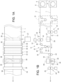
- the alignment device includes a first unrolling device 6 which supports a first roll 7 and continuously unrolls the first continuous sheet panel 1 from the first roll 7, and a second unrolling device 8 which supports a second roll 9 and continuously unrolls the second continuous sheet panel 2 from the second roll 9.
- first sheet panel 1 is located lower, and the second sheet panel 2 is located upper.
- the bag making apparatus includes a first feed device 10 configured to intermittently feed the first sheet panel 1.
- the first feed device 10 includes a pair of feed rollers 11 and a motor 12 for driving the pair of feed rollers 11. When the pair of feed rollers 11 is driven by the motor 12, at least one of the rollers revolves. This causes the first sheet panel 1 sandwiched between the pair of feed rollers 11 to be fed in the longitudinal direction thereof.
- the bag making apparatus includes a second feed device 13.
- the second feed device 13 includes a feed unit 14 configured to intermittently feed the second sheet panel 2 and a stretching unit 15 disposed downstream of the feed unit 14 to apply tension to the second sheet panel 2 in an adjustable manner.
- the stretching unit 15 includes a stretching roller 18 that engages with the second sheet panel 2 to apply tension to the second sheet panel 2, an actuator 19 (e.g., an air cylinder) that moves the stretching roller 18, and two guide rollers 20 that are located upstream and downstream adjacent to the stretching roller 18.
- the tension of the second sheet panel 2 increases when the stretching roller 18 is moved downward by the actuator 19, and decreases when the stretching roller 18 is moved upward by the actuator 19.
- the stretching unit 15 can move the stretching rollers 18 to adjust the tension of the second sheet panel 2, thereby stretching the second sheet panel 2.
- the alignment device includes a well-known dancer device 21 disposed between the first unrolling device 6 and the first feed device 10 and between the second unrolling device 8 and the second feed device 13 to appropriately convert the continuous feed of the respective first and second sheet panels 1 and 2 into the intermittent feed.
- the alignment device includes a pair of guide rollers 22 disposed downstream of the first and second feed devices 10 and 13.
- the first sheet panel 1 is fed to the pair of guide rollers 22, and the second sheet panel 2 is fed to the pair of guide rollers 22 via a guide roller 23, so that the first and second sheet panels 1 and 2 pass through the pair of guide rollers 22.
- This causes the first and second sheet panels 1 and 2 to be superposed on each other by the pair of guide rollers 22 and be fed out of the pair of guide rollers 22 in the superposed state.
- the aligning device includes a third feed device 24 disposed downstream of the pair of guide rollers 22 to intermittently feed the first and second sheet panels 1 and 2 which have been superposed on each other by the pair of guide rollers 22.
- the third feed device 24 includes a pair of feed rollers 25 and a motor 26 for driving the pair of feed rollers 25.
- a pair of feed rollers 25 When the pair of feed rollers 25 is driven by the motor 26, at least one of the rollers revolves. This causes the first and second sheet panels 1 and 2 sandwiched between the pair of feed rollers 25 to be fed in the longitudinal direction thereof.
- rubber rollers are used as the pairs of feed rollers 11, 16 and 25.
- Servo motors are used as the motors 12, 17, and 26.
- the first fixing device 27 in the implementation is a side gusset supply device configured to supply a side gusset 3 as the additional component to the first sheet panel 1 in the width direction of the sheet panel 1, arrange the side gusset 3 in the width direction of the sheet panel 1 such that the longitudinal centerline of the side gusset 3 is aligned with the first fixing position 28, and temporarily fix the side gusset 3 to the first sheet panel 1 by means of ultrasonic-sealing or heat-sealing. Since such a side gusset supply device is well known, its explanation is omitted. As is well-known, the side gusset 3 is supplied to the first sheet panel 1 in a state of being folded in advance in halves on the opposite sides thereof with respect to the longitudinal centerline thereof.
- the first fixing device 27 places the side gusset 3 on the lower sheet panel 1 and temporarily fixes it to the sheet panel 1. Therefore, when the first and second sheet panels 1 and 2 are superposed on each other by the pair of guide rollers 22, the side gusset 3 is interposed between the first and second sheet panels 1 and 2.
- the alignment device includes a second fixing device 29.
- the second fixing device 29 fixes the second sheet panel 2 to the additional component 3 (which has already been fixed to the first sheet panel 1) at the second fixing position 30 downstream of the pair of guide rollers 22 and upstream of the third feed device 24 during every pause phase of the intermittent feed cycle.
- the second fixing device 29 fixes the first and second sheet panels 1 and 2 to each other via the additional component 3.
- the first and second sheet panels 1 and 2 have been initially set in the bag making apparatus such that the print patterns of the first sheet panel 1 and the print patterns of the second sheet panel 2 are roughly aligned with each other.
- the facing surfaces of the first and second sheet panels 1 and 2 are formed of sealant, and their opposite surfaces are formed of base material.
- the outer surfaces of the side gussets 3 folded in halves are formed of sealant, and their inner surfaces are formed of base material.
- the alignment device further includes a third sensor 34 disposed to be able to detect the detection points 37 of the first sheet panel 1 at a position downstream of the second fixing device 29 and upstream of the third feed device 24 (the pair of feed rollers 25).
- the first feed device 10 adjusts the intermittent feed amount thereof based on the output of the first sensor 31 such that a design position 41 of the first sheet panel 1 is aligned with the first fixing position 28 every pause phase of the intermittent feed cycle.
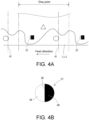
- the first feed device 10 detects the movement amount of the first sensor 31 up to the moment when it detects the line 38, and then adds the number of revolutions corresponding to this movement amount, to the number of revolutions of the pair of feed rollers 11 for the next intermittent feed cycle.
- the first sensor 31 is moved in the feed direction until it detects a line 38.
- the first feed device 10 detects the movement amount of the first sensor 31 up to the moment when it detects the line 38, and then subtracts the number of revolutions corresponding to this movement amount, from the number of revolutions of the pair of feed rollers 11 for the next intermittent feed cycle. In this way, the intermittent feed amount (the number of revolutions of the pair of feed rollers 11) is adjusted in response to the output of the first sensor 31.
- the feed speed of the sheet panel 1 gradually increases, becomes constant, and then decreases to zero. It is designed that a line 38 would pass through the detecting position of the first sensor 31 just before the sheet panel 1 is paused. Therefore, as a general control, the first feed device 10 halts the revolution of the pair of feed rollers 11 via the motor 12 at the moment when the first sensor 31 detects a line 38.
- the design positions 41 also repeat at the print pitch in the same way as the detection points 37 do. Placing the first fixing device 27 in position in advance allows the positional relationship between the design position(s) 41 of the first sheet panel 1 and the first fixing position 28 of the first fixing device 27 to correspond to the positional relationship between the detecting point(s) 37 of the first sheet panel 1 and the detecting position of the first sensor 31. This allows a design position 41 of the first sheet panel 1 to be aligned with the first fixing position 28 every pause phase of the intermittent feed cycle.
- the second feed device 13 adjusts the tension of the second sheet panel 2 and the intermittent feed amount of the feed unit 14 based on the output of the second sensors 32 and 33 such that a design position 41 of the second sheet panel 2 is aligned with the second fixing position 30 during every pause phase of the intermittent feed cycle.
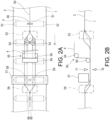
- An open surface seal device 57 heat-seals the side gusset 3 to the sheet panels 1 and 2 and the bottom gusset 4 along the diagonals of the open surfaces 54 in the width direction of the sheet panels 1 and 2 every intermittent feed cycle. Thereby, auxiliary sealed sections 58 are formed. The bottom gusset 4 is adhered to the open surfaces 54 by the auxiliary sealed sections 58.
- another guide device 59 guides the sheet panel 2 such that the sheet panel 2 is folded back.
- the folding back of the sheet panel 2 causes the open surfaces 54 to be closed, resulting in forming auxiliary gussets 60 from the open surfaces 54.
- the folding back of the sheet panel 2 causes the bottom gusset 4 to be folded in halves on the opposite sides thereof with respect to the longitudinal centerline thereof (which is parallel to the longitudinal direction of the sheet panels 1 and 2).
- a longitudinal seal device 61 heat-seals the sheet panes 1 and 2 and the bottom gusset 4 at the longitudinal centerline of the bottom gusset 4 in the longitudinal direction of the sheet panels 1 and 2 to form a longitudinal sealed section 62 every intermittent feed cycle.
- a cross seal device 63 heat-seals the sheet panels 1 and 2, the side gusset 3, and the bottom gusset 4 at the longitudinal centerline of the side gusset 3 in the width direction of the sheet panels 1 and 2 to form a cross sealed section 64 every intermittent feed cycle of the sheet panels 1 and 2.
- a slit device 65 slits the sheet panels 1 and 2, the side gusset 3, and the bottom gusset 4 at the longitudinal centerline of the bottom gusset 4 in the longitudinal direction of the sheet panels 1 and 2.
- a cross cut device 67 cross-cuts the sheet panels 1 and 2, the side gusset 3, and the bottom gusset 4 at the cross sealed section 64 in the width direction of the sheet panels 1 and 2 every intermittent feed cycle of the sheet panels 1 and 2. Thereby, in the implementation, two bags 5 are made each time the cross-cutting is performed.
- the alignment device may further include additional sensors 70 and 71 for alignment of the bottom gusset 4 with the sheet panel 1 as illustrated in FIG. 2B .
- the detection points (not shown) are printed on the bottom gusset 4 at the same print pitch as one of the sheet panels 1 and 2.
- the sensor 70 detects the detection points 37 of the sheet panel 1, and the sensor 71 detects the detection points of the bottom gusset 4.
- the alignment device decreases the upstream tension of the bottom gusset 4.
- the sensor 71 has already detected a detection point of the bottom gusset 4 at the timing when the sensor 70 detects a detection point 37 of the sheet panel 1, this means an advance in supplying the bottom gusset 4.
- it increases the upstream tension of the bottom gusset 4. Repeating this prevents the positional misalignment between the bottom gusset 4 and the sheet panel 1.
- the implementation prevents positional misalignment among the sheet panels 1 and 2, the side gusset(s) 3, and the bottom gusset 4 in the longitudinal direction of the sheet panels 1 and 2. Therefore, when the bags 5 are completed, the print patterns are aligned with one another among the components 1, 2, 3, and 4. The good appearance of the bags 5 is guaranteed.
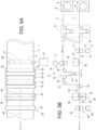
- FIGs. 5A and 5B illustrate the alignment device in the second implementation.
- This implementation dispenses with the upstream sensor 32 ( FIG. 1B ). Therefore, the second sensor consists of the single downstream sensor 33.
- the second feed device 13 adjusts the tension of the second sheet panel 2 and the intermittent feed amount of the feed unit 14 only based on the output of the downstream sensor 33.
- the stretching unit 15 adjusts the tension of the second sheet panel 2 in response to the output of the downstream sensor 33 in the same way as the first implementation, and the feed unit 14 adjusts the number of revolutions of the pair of feed rollers 16 in response to the adjustment of the tension of the second sheet panel 2.
- the stretching unit 15 slightly moves the stretching roller 18 upward to decrease the tension of the second sheet panel 2.
- the feed unit 14 determines that the feed amount thereof is insufficient, and increases the number of revolutions of the pair of feed rollers 16 for the next intermittent feed cycle to the appropriate number of revolutions.
- the stretching unit 15 slightly moves the stretching roller 18 downward to increase the tension of the second sheet panel 2.
- the feed unit 14 then decreases the number of revolutions of the pair of feed rollers 16 for the next intermittent feed cycle to the appropriate number of revolutions.
- Such control also allows a design position 41 of the second sheet panel 2 to be aligned with the second fixing position 30 during every pause phase of the intermittent feed cycle, preventing positional misalignment between the first and second sheet panels 1 and 2 at the second fixing position 30.
- the first fixing position 28 where the first fixing device 27 fixes a side gusset 3 may be a position downstream of the pair of feed rollers 11 and upstream of the first sensor 31.
- sheet panels each with print patterns are used as the first and second sheet panels 1 and 2.
- the intermittent feed amount of the upstream first feed device 10 is controlled based on the output of the first sensor 31, i.e., the positions of the print patterns of the first sheet panel 1.
- the intermittent feed amount of the downstream third feed device 24 is controlled based on the output of the third sensor 34, i.e., the positions of the print patterns of the first sheet panel 1.
- the intermittent feed amounts at the respective positions of both devices 10 and 24 are kept equal to each other, so that the tension of the sheet panel 1 is maintained constant.
- the output of the sensor 31 and the output of the sensor 34 are not used in replacing the sheet panels with new ones in the bag making apparatus of each implementation.
- the sheet panels with no print patterns can be used in the bag making apparatus of each implementation, also in this case, the output of the sensor 31 and the output of the sensor 34 are not used.
- these intermittent feed amounts may differ from one another due to a subtle difference in roller diameter and/or the number of roller revolutions. Therefore, the tension of the first sheet panel 1 may become too high or too low between the first feed device 10 and the third feed device 24.
- the new first sheet panel 1 may be fed by the third pair of feed rollers 25 and tensioned correctly by the upstream dancer 21 with the grip by the first pair of feed rollers 11 released.
- This solves the above problem regarding the tension of the first sheet panel 1 and ensures proper feeding.
- the first pair of feed rollers 11 and the third pair of feed rollers 25 can be controlled based on the output of the first sensor 31 and the output of the third sensor 34, respectively, to achieve accurate feeding.
Landscapes
- Engineering & Computer Science (AREA)
- Mechanical Engineering (AREA)
- Making Paper Articles (AREA)
Claims (6)
- Ausrichtvorrichtung zur Verwendung in einer Beutelherstellungsanlage zur Herstellung von Beuteln (5) aus einem ersten kontinuierlichen Blattpaneel (1), einem zweiten kontinuierlichen Blattpaneel (2) und zusätzlichen Komponenten (3), wobei sowohl das erste als auch das zweite kontinuierliche Blattpaneel (1, 2) Druckmuster aufweisen, die sich in einem Druckabstand wiederholen, und in denen jeweils ein Erkennungspunkt (37) enthalten ist, wobei Design-Positionen (41) auf sowohl dem ersten als auch dem zweiten kontinuierlichen Blattpaneel (1, 2) in dem Druckabstand vorbestimmt sind,
wobei die Ausrichtvorrichtung umfasst:eine erste Zuführvorrichtung (10), die dazu eingerichtet ist, das erste kontinuierliche Blattpaneel (1) intermittierend zuzuführen;eine zweite Zuführvorrichtung (13), die eine Zuführeinheit (14), die dazu eingerichtet ist, das zweite kontinuierliche Blattpaneel (2) intermittierend zuzuführen, und eine der Zuführeinheit (14) nachgelagerte Streckeinheit (15) umfasst, um auf anpassbare Weise eine Spannung an das zweite kontinuierliche Blattpaneel (2) anzulegen;ein Paar von Führungswalzen (22), die der ersten und der zweiten Zuführvorrichtung (10, 13) nachgelagert sind;eine dritte Zuführvorrichtung (24), die dem Paar von Führungswalzen (22) nachgelagert ist, um das erste und das zweite kontinuierliche Blattpaneel (1, 2), die durch das Paar von Führungswalzen (22) übereinander angeordnet sind, intermittierend zuzuführen;eine erste Fixiervorrichtung (27), die dazu eingerichtet ist, während jeder Pausenphase eines intermittierenden Zuführzyklus eine zusätzliche Komponente (3) an einer ersten Fixierposition (28), die der ersten Zuführvorrichtung (10) nachgelagert und dem Paar von Führungswalzen (22) vorgelagert ist, an dem ersten kontinuierlichen Blattpaneel (1) zu fixieren;eine zweite Fixiervorrichtung (29), die dazu eingerichtet ist, während jeder Pausenphase eines intermittierenden Zuführzyklus das zweite kontinuierliche Blattpaneel (2) an einer zweiten Fixierposition (30), die dem Paar von Führungswalzen (22) nachgelagert und der dritten Zuführvorrichtung (24) vorgelagert ist, an der zusätzlichen Komponente (3) zu fixieren;einen ersten Sensor (31) zum Detektieren des Detektionspunkts (37) des ersten kontinuierlichen Blattpaneels (1) an einer Position, die der ersten Zuführvorrichtung (10) nachgelagert und dem Paar von Führungswalzen (22) vorgelagert ist;mindestens einen zweiten Sensor (32, 33) zum Detektieren des Detektionspunkts (37) des zweiten kontinuierlichen Blattpaneels (2) an einer Position, die der zweiten Fixiervorrichtung (29) vorgelagert ist; undeinen dritten Sensor (34) zum Detektieren des Detektionspunkts (37) des ersten kontinuierlichen Blattpaneels (1) an einer Position, die der zweiten Fixiervorrichtung (29) nachgelagert und der dritten Zuführvorrichtung (24) vorgelagert ist,wobei die erste Zuführvorrichtung (10) ferner dazu eingerichtet ist, während jeder Pausenphase eines intermittierenden Zuführzyklus eine von ihr intermittierend zugeführte Menge auf Basis einer Ausgabe des ersten Sensors (31) so anzupassen, dass eine Design-Position (41) des ersten Blattpaneels (1) an der ersten Fixierposition (28) ausgerichtet wird,wobei die dritte Zuführvorrichtung (24) ferner dazu eingerichtet ist, während jeder Pausenphase eines intermittierenden Zuführzyklus eine von ihr intermittierend zugeführte Menge auf Basis einer Ausgabe des dritten Sensors (34) so anzupassen, dass die Design-Position (41) des ersten kontinuierlichen Blattpaneels (1) an der zweiten Fixierposition (30) ausgerichtet wird,wobei die zweite Zuführvorrichtung (13) ferner dazu eingerichtet ist, während jeder Pausenphase eines intermittierenden Zuführzyklus die Zugspannung und eine von der Zuführeinheit (14) intermittierend zugeführte Menge auf Basis einer Ausgabe des mindestens einen zweiten Sensors (32, 33) so anzupassen, dass eine Design-Position (41) des zweiten kontinuierlichen Blattpaneels (2) an der zweiten Fixierposition (30) ausgerichtet wird. - Ausrichtvorrichtung nach Anspruch 1, wobei der mindestens eine zweite Sensor (32, 33) einen nachgelagerten Sensor (33) zum Detektieren des Detektionspunkts (37) des zweiten kontinuierlichen Blattpaneels (2) an einer Position, die dem Paar von Führungswalzen (22) nachgelagert und der zweiten Fixiervorrichtung (29) vorgelagert ist, umfasst.
- Ausrichtvorrichtung nach Anspruch 2, wobei der mindestens eine zweite Sensor (32, 33) ferner einen vorgelagerten Sensor (32) zum Detektieren des Detektionspunkts (37) des zweiten kontinuierlichen Blattpaneels (2) an einer Position, die der Zuführeinheit (14) vorgelagert ist, umfasst,wobei die Zuführeinheit (14) dazu eingerichtet ist, die von ihr intermittierend zugeführte Menge als Reaktion auf eine Ausgabe des vorgelagerten Sensors (32) anzupassen, undwobei die Streckeinheit (15) dazu eingerichtet ist, die Zugspannung als Reaktion auf eine Ausgabe des nachgelagerten Sensors (33) anzupassen.
- Ausrichtvorrichtung nach Anspruch 2, wobei die Streckeinheit (15) dazu eingerichtet ist, die Zugspannung als Reaktion auf eine Ausgabe des nachgelagerten Sensors (33) anzupassen, und
wobei die Zuführeinheit (14) dazu eingerichtet ist, die von ihr intermittierend zugeführte Menge als Reaktion auf die Anpassung der Zugspannung anzupassen. - Ausrichtvorrichtung nach einem der Ansprüche 1 bis 4, wobei die erste Fixiervorrichtung (27) eine Seitenzwickelzuführvorrichtung ist, die dazu eingerichtet ist, einen Seitenzwickel als die zusätzliche Komponente (3) zu dem ersten kontinuierlichen Blattpaneel (1) zu liefern, den Seitenzwickel (3) in der Breitenrichtung des ersten kontinuierlichen Blattpaneels (1) anzuordnen und den Seitenzwickel (3) vorläufig an dem ersten kontinuierlichen Blattpaneel (1) zu fixieren, und
wobei die zweite Fixiervorrichtung (29) eine Siegelungsvorrichtung ist, die dazu eingerichtet ist, den Seitenzwickel (3) an das erste und das zweite kontinuierliche Blattpaneel (1, 2) zu siegeln. - Ausrichtvorrichtung nach einem der Ansprüche 1 bis 5, wobei die erste Zuführvorrichtung (10) dazu eingerichtet ist, das erste kontinuierliche Blattpaneel (1) abgerollt von einer ersten Rolle (7) intermittierend zuzuführen, und
wobei die zweite Zuführvorrichtung (29) dazu eingerichtet ist, das zweite kontinuierliche Blattpaneel (2) abgerollt von einer zweiten Rolle (9) intermittierend zuzuführen.
Applications Claiming Priority (2)
| Application Number | Priority Date | Filing Date | Title |
|---|---|---|---|
| JP2019223720 | 2019-12-11 | ||
| PCT/JP2020/037446 WO2021117321A1 (ja) | 2019-12-11 | 2020-10-01 | 位置合わせ装置 |
Publications (3)
| Publication Number | Publication Date |
|---|---|
| EP4074636A1 EP4074636A1 (de) | 2022-10-19 |
| EP4074636A4 EP4074636A4 (de) | 2023-04-26 |
| EP4074636B1 true EP4074636B1 (de) | 2025-04-16 |
Family
ID=76329363
Family Applications (1)
| Application Number | Title | Priority Date | Filing Date |
|---|---|---|---|
| EP20897663.9A Active EP4074636B1 (de) | 2019-12-11 | 2020-10-01 | Ausrichtungsvorrichtung |
Country Status (5)
| Country | Link |
|---|---|
| US (1) | US12180022B2 (de) |
| EP (1) | EP4074636B1 (de) |
| JP (1) | JP7161160B2 (de) |
| CN (1) | CN114728485B (de) |
| WO (1) | WO2021117321A1 (de) |
Families Citing this family (4)
| Publication number | Priority date | Publication date | Assignee | Title |
|---|---|---|---|---|
| JP7180926B2 (ja) * | 2020-06-30 | 2022-11-30 | トタニ技研工業株式会社 | 欠陥検出装置、および、製袋機 |
| JP7677806B2 (ja) * | 2021-02-26 | 2025-05-15 | 株式会社細川洋行 | 製袋機の制御装置、製袋機、袋、製袋機の制御方法、及び製袋機の制御プログラム |
| JP7693182B2 (ja) * | 2023-06-28 | 2025-06-17 | トタニ技研工業株式会社 | ウェブ形成装置および形成方法、および、二重袋の製袋機 |
| JP7849061B2 (ja) * | 2024-06-04 | 2026-04-21 | トタニ技研工業株式会社 | 製袋機および製袋方法 |
Family Cites Families (22)
| Publication number | Priority date | Publication date | Assignee | Title |
|---|---|---|---|---|
| US3345919A (en) * | 1965-02-18 | 1967-10-10 | Union Carbide Corp | Continuous bag making machine |
| JPS5346113B2 (de) | 1973-09-20 | 1978-12-11 | ||
| JP3534580B2 (ja) * | 1997-09-19 | 2004-06-07 | 株式会社細川洋行 | フラットボトム包装袋の製造方法及び製造装置 |
| JP4121722B2 (ja) | 2001-08-07 | 2008-07-23 | トタニ技研工業株式会社 | プラスチックフィルムの印刷ピッチ矯正装置 |
| JP3872449B2 (ja) | 2003-06-09 | 2007-01-24 | トタニ技研工業株式会社 | プラスチックフィルムの印刷ピッチ矯正装置 |
| JP2008169017A (ja) | 2007-01-15 | 2008-07-24 | Daisan Shigyo Kk | 袋製造装置 |
| CN102066219B (zh) | 2008-07-11 | 2013-07-24 | 户谷技研工业株式会社 | 塑料薄膜延伸装置 |
| JP5880808B2 (ja) * | 2011-04-21 | 2016-03-09 | 東洋製罐株式会社 | 製袋装置 |
| JP5825718B2 (ja) * | 2012-02-14 | 2015-12-02 | 西部機械株式会社 | 製袋機 |
| JP5346113B1 (ja) | 2012-10-05 | 2013-11-20 | トタニ技研工業株式会社 | プラスチックフィルムの印刷ピッチ矯正装置 |
| CN203237831U (zh) * | 2013-04-10 | 2013-10-16 | 上海洲泰轻工机械制造有限公司 | 一种制袋薄膜的张力控制装置 |
| JP5635651B1 (ja) | 2013-06-18 | 2014-12-03 | トタニ技研工業株式会社 | 製袋機 |
| JP5584815B1 (ja) * | 2013-12-26 | 2014-09-03 | 株式会社リングストン | 合成樹脂製ガゼット袋の製造方法及び製造装置 |
| JP6288771B2 (ja) | 2014-06-10 | 2018-03-07 | トタニ技研工業株式会社 | ウエブ材間欠送り装置 |
| JP5965509B1 (ja) * | 2015-03-24 | 2016-08-03 | トタニ技研工業株式会社 | 製袋機 |
| US10493715B2 (en) * | 2015-06-11 | 2019-12-03 | Totani Corporation | Apparatus and method for making plastic bags |
| JP2017128017A (ja) | 2016-01-19 | 2017-07-27 | 西部機械株式会社 | 底ガゼットを有する袋を製袋する製袋機 |
| WO2017216927A1 (ja) * | 2016-06-16 | 2017-12-21 | ユニ・チャーム株式会社 | 吸収性物品に係るシート状部材の製造方法、及び製造装置 |
| CN107718709A (zh) * | 2017-11-21 | 2018-02-23 | 无锡市铁民印刷机械有限公司 | 双放料制袋机的上下膜图案对准机构 |
| CN112469650B (zh) * | 2018-08-02 | 2022-07-29 | 户谷技研工业株式会社 | 间歇输送装置 |
| EP3974168A4 (de) * | 2019-05-21 | 2022-09-14 | Totani Corporation | Beutelherstellungsverfahren und beutelherstellungsvorrichtung |
| CN116133834B (zh) * | 2020-09-25 | 2025-11-07 | 户谷技研工业株式会社 | 制袋机 |
-
2020
- 2020-10-01 CN CN202080075946.8A patent/CN114728485B/zh active Active
- 2020-10-01 WO PCT/JP2020/037446 patent/WO2021117321A1/ja not_active Ceased
- 2020-10-01 US US17/782,609 patent/US12180022B2/en active Active
- 2020-10-01 EP EP20897663.9A patent/EP4074636B1/de active Active
- 2020-10-01 JP JP2021540201A patent/JP7161160B2/ja active Active
Also Published As
| Publication number | Publication date |
|---|---|
| EP4074636A1 (de) | 2022-10-19 |
| CN114728485B (zh) | 2023-08-25 |
| JP7161160B2 (ja) | 2022-10-26 |
| WO2021117321A1 (ja) | 2021-06-17 |
| EP4074636A4 (de) | 2023-04-26 |
| CN114728485A (zh) | 2022-07-08 |
| US12180022B2 (en) | 2024-12-31 |
| US20230014103A1 (en) | 2023-01-19 |
| JPWO2021117321A1 (de) | 2021-06-17 |
Similar Documents
| Publication | Publication Date | Title |
|---|---|---|
| EP4074636B1 (de) | Ausrichtungsvorrichtung | |
| EP2969518B1 (de) | Verfahren zur ausführung mehrerer aufgaben auf einer materialbahn | |
| EP3831753B1 (de) | Intermittierende transportvorrichtung | |
| US6217497B1 (en) | Stand-up apparatus for producing flexible pouches | |
| US20170203532A1 (en) | Plastic Bag Making Apparatus | |
| US12350902B2 (en) | Bag making method and bag making apparatus | |
| JP2005080827A (ja) | 吸収性物品の製造方法 | |
| JP4121722B2 (ja) | プラスチックフィルムの印刷ピッチ矯正装置 | |
| EP2177347B1 (de) | Rotierende Beutelmaschine | |
| JP7180932B1 (ja) | 製袋機、および、製袋方法 | |
| JPH06170989A (ja) | 製袋機 | |
| US20020053184A1 (en) | Automatic web height control in a packaging machine | |
| EP3911505B1 (de) | Vorrichtung und verfahren zum befestigen eines reissverschlusses an einem polymerfilm | |
| US3282173A (en) | Thermoplastic bag manufacturing apparatus | |
| JP7693182B2 (ja) | ウェブ形成装置および形成方法、および、二重袋の製袋機 | |
| JPH09309096A (ja) | フィルムシート切込み用カッター装置及びフィルムシートのヒートシール装置 | |
| JPH10119910A (ja) | 横型製袋充填機のフィルム移送装置 | |
| JP7516880B2 (ja) | 製袋装置、及び袋状の包装容器の製造方法 | |
| US20100197473A1 (en) | Rotary Bag Machine | |
| WO2026023311A1 (ja) | ウェブ形成装置、ウェブ形成方法、および、製袋機 | |
| WO2022180986A1 (ja) | 製袋方法、および、製袋機 |
Legal Events
| Date | Code | Title | Description |
|---|---|---|---|
| STAA | Information on the status of an ep patent application or granted ep patent |
Free format text: STATUS: THE INTERNATIONAL PUBLICATION HAS BEEN MADE |
|
| PUAI | Public reference made under article 153(3) epc to a published international application that has entered the european phase |
Free format text: ORIGINAL CODE: 0009012 |
|
| STAA | Information on the status of an ep patent application or granted ep patent |
Free format text: STATUS: REQUEST FOR EXAMINATION WAS MADE |
|
| 17P | Request for examination filed |
Effective date: 20220505 |
|
| AK | Designated contracting states |
Kind code of ref document: A1 Designated state(s): AL AT BE BG CH CY CZ DE DK EE ES FI FR GB GR HR HU IE IS IT LI LT LU LV MC MK MT NL NO PL PT RO RS SE SI SK SM TR |
|
| DAV | Request for validation of the european patent (deleted) | ||
| DAX | Request for extension of the european patent (deleted) | ||
| A4 | Supplementary search report drawn up and despatched |
Effective date: 20230324 |
|
| RIC1 | Information provided on ipc code assigned before grant |
Ipc: B31B 160/20 20170101ALN20230320BHEP Ipc: B31B 155/00 20170101ALN20230320BHEP Ipc: B31B 70/26 20170101ALI20230320BHEP Ipc: B31B 70/64 20170101ALI20230320BHEP Ipc: B31B 70/10 20170101ALI20230320BHEP Ipc: B65H 23/188 20060101AFI20230320BHEP |
|
| GRAP | Despatch of communication of intention to grant a patent |
Free format text: ORIGINAL CODE: EPIDOSNIGR1 |
|
| STAA | Information on the status of an ep patent application or granted ep patent |
Free format text: STATUS: GRANT OF PATENT IS INTENDED |
|
| RIC1 | Information provided on ipc code assigned before grant |
Ipc: B31B 160/20 20170101ALN20241016BHEP Ipc: B31B 155/00 20170101ALN20241016BHEP Ipc: B31B 70/00 20170101ALI20241016BHEP Ipc: B31B 70/26 20170101ALI20241016BHEP Ipc: B31B 70/64 20170101ALI20241016BHEP Ipc: B31B 70/10 20170101ALI20241016BHEP Ipc: B65H 23/188 20060101AFI20241016BHEP |
|
| INTG | Intention to grant announced |
Effective date: 20241108 |
|
| GRAS | Grant fee paid |
Free format text: ORIGINAL CODE: EPIDOSNIGR3 |
|
| GRAA | (expected) grant |
Free format text: ORIGINAL CODE: 0009210 |
|
| STAA | Information on the status of an ep patent application or granted ep patent |
Free format text: STATUS: THE PATENT HAS BEEN GRANTED |
|
| AK | Designated contracting states |
Kind code of ref document: B1 Designated state(s): AL AT BE BG CH CY CZ DE DK EE ES FI FR GB GR HR HU IE IS IT LI LT LU LV MC MK MT NL NO PL PT RO RS SE SI SK SM TR |
|
| REG | Reference to a national code |
Ref country code: GB Ref legal event code: FG4D |
|
| REG | Reference to a national code |
Ref country code: CH Ref legal event code: EP |
|
| REG | Reference to a national code |
Ref country code: IE Ref legal event code: FG4D |
|
| REG | Reference to a national code |
Ref country code: DE Ref legal event code: R096 Ref document number: 602020049730 Country of ref document: DE |
|
| REG | Reference to a national code |
Ref country code: NL Ref legal event code: MP Effective date: 20250416 |
|
| PG25 | Lapsed in a contracting state [announced via postgrant information from national office to epo] |
Ref country code: NL Free format text: LAPSE BECAUSE OF FAILURE TO SUBMIT A TRANSLATION OF THE DESCRIPTION OR TO PAY THE FEE WITHIN THE PRESCRIBED TIME-LIMIT Effective date: 20250416 |
|
| REG | Reference to a national code |
Ref country code: AT Ref legal event code: MK05 Ref document number: 1785537 Country of ref document: AT Kind code of ref document: T Effective date: 20250416 |
|
| PG25 | Lapsed in a contracting state [announced via postgrant information from national office to epo] |
Ref country code: FI Free format text: LAPSE BECAUSE OF FAILURE TO SUBMIT A TRANSLATION OF THE DESCRIPTION OR TO PAY THE FEE WITHIN THE PRESCRIBED TIME-LIMIT Effective date: 20250416 Ref country code: PT Free format text: LAPSE BECAUSE OF FAILURE TO SUBMIT A TRANSLATION OF THE DESCRIPTION OR TO PAY THE FEE WITHIN THE PRESCRIBED TIME-LIMIT Effective date: 20250818 Ref country code: ES Free format text: LAPSE BECAUSE OF FAILURE TO SUBMIT A TRANSLATION OF THE DESCRIPTION OR TO PAY THE FEE WITHIN THE PRESCRIBED TIME-LIMIT Effective date: 20250416 |
|
| REG | Reference to a national code |
Ref country code: LT Ref legal event code: MG9D |
|
| PG25 | Lapsed in a contracting state [announced via postgrant information from national office to epo] |
Ref country code: NO Free format text: LAPSE BECAUSE OF FAILURE TO SUBMIT A TRANSLATION OF THE DESCRIPTION OR TO PAY THE FEE WITHIN THE PRESCRIBED TIME-LIMIT Effective date: 20250716 Ref country code: GR Free format text: LAPSE BECAUSE OF FAILURE TO SUBMIT A TRANSLATION OF THE DESCRIPTION OR TO PAY THE FEE WITHIN THE PRESCRIBED TIME-LIMIT Effective date: 20250717 |
|
| PG25 | Lapsed in a contracting state [announced via postgrant information from national office to epo] |
Ref country code: PL Free format text: LAPSE BECAUSE OF FAILURE TO SUBMIT A TRANSLATION OF THE DESCRIPTION OR TO PAY THE FEE WITHIN THE PRESCRIBED TIME-LIMIT Effective date: 20250416 |
|
| PG25 | Lapsed in a contracting state [announced via postgrant information from national office to epo] |
Ref country code: BG Free format text: LAPSE BECAUSE OF FAILURE TO SUBMIT A TRANSLATION OF THE DESCRIPTION OR TO PAY THE FEE WITHIN THE PRESCRIBED TIME-LIMIT Effective date: 20250416 |
|
| PG25 | Lapsed in a contracting state [announced via postgrant information from national office to epo] |
Ref country code: HR Free format text: LAPSE BECAUSE OF FAILURE TO SUBMIT A TRANSLATION OF THE DESCRIPTION OR TO PAY THE FEE WITHIN THE PRESCRIBED TIME-LIMIT Effective date: 20250416 |
|
| PG25 | Lapsed in a contracting state [announced via postgrant information from national office to epo] |
Ref country code: AT Free format text: LAPSE BECAUSE OF FAILURE TO SUBMIT A TRANSLATION OF THE DESCRIPTION OR TO PAY THE FEE WITHIN THE PRESCRIBED TIME-LIMIT Effective date: 20250416 |
|
| PG25 | Lapsed in a contracting state [announced via postgrant information from national office to epo] |
Ref country code: RS Free format text: LAPSE BECAUSE OF FAILURE TO SUBMIT A TRANSLATION OF THE DESCRIPTION OR TO PAY THE FEE WITHIN THE PRESCRIBED TIME-LIMIT Effective date: 20250716 |
|
| PG25 | Lapsed in a contracting state [announced via postgrant information from national office to epo] |
Ref country code: IS Free format text: LAPSE BECAUSE OF FAILURE TO SUBMIT A TRANSLATION OF THE DESCRIPTION OR TO PAY THE FEE WITHIN THE PRESCRIBED TIME-LIMIT Effective date: 20250816 |
|
| PG25 | Lapsed in a contracting state [announced via postgrant information from national office to epo] |
Ref country code: LV Free format text: LAPSE BECAUSE OF FAILURE TO SUBMIT A TRANSLATION OF THE DESCRIPTION OR TO PAY THE FEE WITHIN THE PRESCRIBED TIME-LIMIT Effective date: 20250416 |
|
| PGFP | Annual fee paid to national office [announced via postgrant information from national office to epo] |
Ref country code: DE Payment date: 20251021 Year of fee payment: 6 |
|
| PG25 | Lapsed in a contracting state [announced via postgrant information from national office to epo] |
Ref country code: DK Free format text: LAPSE BECAUSE OF FAILURE TO SUBMIT A TRANSLATION OF THE DESCRIPTION OR TO PAY THE FEE WITHIN THE PRESCRIBED TIME-LIMIT Effective date: 20250416 Ref country code: SM Free format text: LAPSE BECAUSE OF FAILURE TO SUBMIT A TRANSLATION OF THE DESCRIPTION OR TO PAY THE FEE WITHIN THE PRESCRIBED TIME-LIMIT Effective date: 20250416 |
|
| PGFP | Annual fee paid to national office [announced via postgrant information from national office to epo] |
Ref country code: IT Payment date: 20251024 Year of fee payment: 6 |
|
| PGFP | Annual fee paid to national office [announced via postgrant information from national office to epo] |
Ref country code: FR Payment date: 20251030 Year of fee payment: 6 |
|
| REG | Reference to a national code |
Ref country code: DE Ref legal event code: R097 Ref document number: 602020049730 Country of ref document: DE |
|
| PG25 | Lapsed in a contracting state [announced via postgrant information from national office to epo] |
Ref country code: CZ Free format text: LAPSE BECAUSE OF FAILURE TO SUBMIT A TRANSLATION OF THE DESCRIPTION OR TO PAY THE FEE WITHIN THE PRESCRIBED TIME-LIMIT Effective date: 20250416 |
|
| PG25 | Lapsed in a contracting state [announced via postgrant information from national office to epo] |
Ref country code: EE Free format text: LAPSE BECAUSE OF FAILURE TO SUBMIT A TRANSLATION OF THE DESCRIPTION OR TO PAY THE FEE WITHIN THE PRESCRIBED TIME-LIMIT Effective date: 20250416 |
|
| PG25 | Lapsed in a contracting state [announced via postgrant information from national office to epo] |
Ref country code: SK Free format text: LAPSE BECAUSE OF FAILURE TO SUBMIT A TRANSLATION OF THE DESCRIPTION OR TO PAY THE FEE WITHIN THE PRESCRIBED TIME-LIMIT Effective date: 20250416 |
|
| PG25 | Lapsed in a contracting state [announced via postgrant information from national office to epo] |
Ref country code: RO Free format text: LAPSE BECAUSE OF FAILURE TO SUBMIT A TRANSLATION OF THE DESCRIPTION OR TO PAY THE FEE WITHIN THE PRESCRIBED TIME-LIMIT Effective date: 20250416 |
|
| PLBE | No opposition filed within time limit |
Free format text: ORIGINAL CODE: 0009261 |
|
| STAA | Information on the status of an ep patent application or granted ep patent |
Free format text: STATUS: NO OPPOSITION FILED WITHIN TIME LIMIT |
|
| REG | Reference to a national code |
Ref country code: CH Ref legal event code: L10 Free format text: ST27 STATUS EVENT CODE: U-0-0-L10-L00 (AS PROVIDED BY THE NATIONAL OFFICE) Effective date: 20260225 |
|
| 26N | No opposition filed |
Effective date: 20260119 |