EP4074932A1 - Stromverteilerkasten und verfahren zur herstellung eines solchen stromverteilerkastens - Google Patents
Stromverteilerkasten und verfahren zur herstellung eines solchen stromverteilerkastens Download PDFInfo
- Publication number
- EP4074932A1 EP4074932A1 EP22168358.4A EP22168358A EP4074932A1 EP 4074932 A1 EP4074932 A1 EP 4074932A1 EP 22168358 A EP22168358 A EP 22168358A EP 4074932 A1 EP4074932 A1 EP 4074932A1
- Authority
- EP
- European Patent Office
- Prior art keywords
- knuckle
- box
- door
- hinge
- groove
- Prior art date
- Legal status (The legal status is an assumption and is not a legal conclusion. Google has not performed a legal analysis and makes no representation as to the accuracy of the status listed.)
- Granted
Links
Images


Classifications
-
- H—ELECTRICITY
- H02—GENERATION; CONVERSION OR DISTRIBUTION OF ELECTRIC POWER
- H02B—BOARDS, SUBSTATIONS OR SWITCHING ARRANGEMENTS FOR THE SUPPLY OR DISTRIBUTION OF ELECTRIC POWER
- H02B1/00—Frameworks, boards, panels, desks, casings; Details of substations or switching arrangements
- H02B1/26—Casings; Parts thereof or accessories therefor
- H02B1/30—Cabinet-type casings; Parts thereof or accessories therefor
- H02B1/38—Hinged covers or doors
-
- E—FIXED CONSTRUCTIONS
- E05—LOCKS; KEYS; WINDOW OR DOOR FITTINGS; SAFES
- E05D—HINGES OR SUSPENSION DEVICES FOR DOORS, WINDOWS OR WINGS
- E05D5/00—Construction of single parts, e.g. the parts for attachment
- E05D5/10—Pins, sockets or sleeves; Removable pins
- E05D5/12—Securing pins in sockets, movably or not
- E05D5/125—Non-removable, snap-fitted pins
-
- E—FIXED CONSTRUCTIONS
- E05—LOCKS; KEYS; WINDOW OR DOOR FITTINGS; SAFES
- E05D—HINGES OR SUSPENSION DEVICES FOR DOORS, WINDOWS OR WINGS
- E05D7/00—Hinges or pivots of special construction
- E05D7/10—Hinges or pivots of special construction to allow easy separation or connection of the parts at the hinge axis
- E05D7/1005—Hinges or pivots of special construction to allow easy separation or connection of the parts at the hinge axis by axially moving free pins, balls or sockets
- E05D7/1022—Hinges or pivots of special construction to allow easy separation or connection of the parts at the hinge axis by axially moving free pins, balls or sockets with snap-fitted pins
-
- E—FIXED CONSTRUCTIONS
- E05—LOCKS; KEYS; WINDOW OR DOOR FITTINGS; SAFES
- E05D—HINGES OR SUSPENSION DEVICES FOR DOORS, WINDOWS OR WINGS
- E05D7/00—Hinges or pivots of special construction
- E05D7/10—Hinges or pivots of special construction to allow easy separation or connection of the parts at the hinge axis
- E05D7/1061—Hinges or pivots of special construction to allow easy separation or connection of the parts at the hinge axis in a radial direction
-
- H—ELECTRICITY
- H02—GENERATION; CONVERSION OR DISTRIBUTION OF ELECTRIC POWER
- H02B—BOARDS, SUBSTATIONS OR SWITCHING ARRANGEMENTS FOR THE SUPPLY OR DISTRIBUTION OF ELECTRIC POWER
- H02B1/00—Frameworks, boards, panels, desks, casings; Details of substations or switching arrangements
- H02B1/26—Casings; Parts thereof or accessories therefor
- H02B1/40—Wall-mounted casings; Parts thereof or accessories therefor
- H02B1/44—Hinged covers or doors
-
- E—FIXED CONSTRUCTIONS
- E05—LOCKS; KEYS; WINDOW OR DOOR FITTINGS; SAFES
- E05Y—INDEXING SCHEME ASSOCIATED WITH SUBCLASSES E05D AND E05F, RELATING TO CONSTRUCTION ELEMENTS, ELECTRIC CONTROL, POWER SUPPLY, POWER SIGNAL OR TRANSMISSION, USER INTERFACES, MOUNTING OR COUPLING, DETAILS, ACCESSORIES, AUXILIARY OPERATIONS NOT OTHERWISE PROVIDED FOR, APPLICATION THEREOF
- E05Y2900/00—Application of doors, windows, wings or fittings thereof
- E05Y2900/20—Application of doors, windows, wings or fittings thereof for furniture, e.g. cabinets
- E05Y2900/208—Application of doors, windows, wings or fittings thereof for furniture, e.g. cabinets for metal cabinets
-
- H—ELECTRICITY
- H02—GENERATION; CONVERSION OR DISTRIBUTION OF ELECTRIC POWER
- H02B—BOARDS, SUBSTATIONS OR SWITCHING ARRANGEMENTS FOR THE SUPPLY OR DISTRIBUTION OF ELECTRIC POWER
- H02B1/00—Frameworks, boards, panels, desks, casings; Details of substations or switching arrangements
- H02B1/26—Casings; Parts thereof or accessories therefor
- H02B1/28—Casings; Parts thereof or accessories therefor dustproof, splashproof, drip-proof, waterproof or flameproof
Definitions
- the present invention relates to an electrical box and a method of manufacturing such an electrical box.
- Such cabinets In the field of industrial electrical installations, it is known to protect electrical equipment in electrical cabinets.
- Such cabinets generally comprise a box and a door, pivotally mounted on the box using hinges.
- hinges of such cabinets have the disadvantage of being impractical to disassemble, the screws having to be removed, which is time-consuming and which therefore does not allow the door of the box to be easily dismantled during a maintenance operation.
- EP-A-3 556 979 describes an electrical cabinet comprising a frame and a door connected together by hinge means which comprise a knuckle, fixed to the door and having a housing, and a pin, fixed to the frame and received in the housing of the knuckle. Dismantling the door of such a cabinet is complex.
- the invention more particularly intends to remedy by proposing an electrical box whose door can be easily removed and whose hinges are simple and inexpensive to produce.
- the invention relates to an electrical box comprising a box defining an opening, a door configured to close the opening of the box when it is in the closed position and at least one hinge, the hinge making it possible to connect the door to the box in a pivoting manner, the hinge comprising a knuckle and a pin.
- the hinge knuckle includes a pin receiving groove extending the full length of the knuckle, and a width of the knuckle is substantially equal to a diameter of the hinge pin.
- the groove of the knuckle of each hinge extends in a groove plane comprising a pivot axis of the door relative to the box.
- the pin is mounted on the door, the knuckle is fixed to the casing, or integral with the casing, and an angle between the groove plane and a plane of the opening of the casing is between 5° and 35 °, preferably between 15° and 25°.
- the door of the electrical box can be easily separated from the casing, by disengaging the pin from the hinge of the knuckle in which it is engaged by the groove of this knuckle.
- the angle formed between the plane of the groove and the plane of the opening makes it possible to move the door away from the box when the pin is withdrawn from the groove.
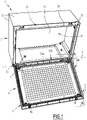
- An electrical box 1 is shown in figures 1 to 5 .
- the electrical box 1 is intended to receive electrical equipment not shown, such as for example circuit breakers, contactors, relays, and/or meters.
- the electrical box 1 is, for example, mounted in an electrical installation and used to accommodate electrical equipment of an energy production installation, such as a wind turbine installation.
- the electrical box 1 comprises a box 3 and a door 5, interconnected by hinges 7.
- the box 3 is of parallelepipedal shape.
- the box 3 comprises a bottom 31 and side walls 33, in the example four side walls 33.
- Each side wall 33 comprises a free edge 35.
- the box 3 defines an opening 37, carried by a plane P37, better visible on the figure 4 and 5 .
- the free edges 35 of the side walls 33 extend in the plane P37.
- the box 3 also comprises a sealing rib 39, which extends from the free edges 35 of the side walls 33 away from the bottom 31.
- the sealing rib 39 is continuous, that is to say say that it surrounds the opening 37 without interruption.
- the door 5 of the electrical box 1 is generally flat and comprises four edges 51.
- the door 5 has dimensions equivalent to those of the bottom 31 of the box.
- One of the edges 51 of the door 5, denoted “51A” is connected to one of the edges 35 of the box 3, denoted "35A”, by the hinges 7, so that the door 5 can pivot relative to the box 3 around the hinges.
- An opening angle ⁇ of the electrical box 1 is defined as being an angle formed between the plane P37 of the opening 37 and a main plane P5 of the door 5.
- the electrical box 1 is closed, that is to say that the door 5 covers the opening 37 of the box 3 and the edges 51 of the door are facing the edges 35 of the box.
- the electrical box 1 When the opening angle ⁇ is greater than zero, then the electrical box 1 is open.
- the maximum opening angle ⁇ of the electrical box 1 is around 180°.
- the maximum opening angle ⁇ of the electrical box 1 is defined by the geometry of the door 5 and of the box 3.
- the maximum opening angle ⁇ of the electrical box 1 is greater, for example d 'about 200°.
- the angle ⁇ is approximately equal to 105°.
- the door 5 further comprises a housing 53 in the form of a groove, formed on the edges 51 all around the door, at the bottom of which a seal 55 is positioned.
- seal 55 is omitted on the figures 1 to 3 .
- the sealing rib 39 of the casing 3 extends into the housing 53 of the door 5, so as to crush the seal 55 at the bottom of the housing. Thanks to the crushing of the seal 55, the electrical box 1 is sealed when it is closed, that is to say that the interior of the electrical box is protected from splashing water and dust, which makes it possible to protect the electrical equipment placed in the box.
- the door 5 comprises locking means 56, which cooperate with the casing 3 to enable the electrical box 1 to be locked in the closed position of the door.
- the door 5 also includes notches 57, provided on the edge 51A. Each notch 57 accommodates a hinge 7, i.e. the hinges are located in the notches 57.
- the door 5 comprises as many notches as the box comprises hinges.
- the electrical box 1 comprises two hinges 7.
- the electrical box 1 comprises a different number of hinges 7, such as for example one, three or four hinges.
- Each hinge 7 includes a pin 8 and a knuckle 9.
- pin 8 of a hinge 7 defines a pivot axis X7 of this hinge.
- the pivot axes of all the hinges 7 are coincident and aligned on a common axis X.
- the common axis X forms a pivot axis of the door 5 with respect to the box 3.
- a spindle 8 comprises a rod 81 and a head 83.
- the rod 81 is cylindrical in shape with a circular section.
- the diameter D81 of the rod 81 is between 2 mm and 8 mm, more preferably equal to 5 mm.
- the rod 81 is fixed at one of its ends to the head 83 and the head 83 makes it possible to maintain the pin 8 fixed to the door 5, as explained below.
- the rod 81 extends in one of the notches 57 of the door 5, crossing this notch right through.
- the rod 81 passes through two holding holes 58 of the edge 51A of the door, the two holding holes being arranged on either side of the notch 57 and aligned on an axis X58. At least one of the holding holes is through, preferably both.
- L57 the length of the notch 57 measured between the holes 58, parallel to the axis X58.
- the length L57 is between 40 mm and 120 mm, more preferably equal to 80 mm.
- the holding holes 58 are provided in two reinforcements 61 of the edge 51A of the door 5.
- Pin 8 is mounted on door 5 by aligning its axis X7 with axis X58 and by engaging rod 81 in the two holding holes 58.
- the head 83 comprises a hook 85, which cooperates with a protrusion 59 of the door 5, so as to prevent the movement of the pin parallel to the axis X58, in a direction of distance of the head from the reinforcement 61 adjacent.
- pin 8 is fixed relative to gate 5.
- pin 8 can be dismantled with respect to door 5.
- hook 85 is elastically deformable.
- pin 8 is not removable.
- the pin 8 comprises two heads, arranged on either side of the rod 81, at least one of the two heads being fixed on the rod after the positioning of the rod through the retaining holes 58.
- the pin comprises only one rod 81, the one of the ends or both ends are folded over so as to prevent its removal from the retaining holes 58. In the latter case, at least one of the two ends of the rod 81 is folded over after the rod has been placed through retaining holes 58.
- the spindle comprises a single head, fixed to the edge 51A by fixing means such as screws.
- fitting rod 81 through retaining holes 58 amounts to fixing pin 8 on door 5.
- the knuckle 9 of a hinge 7 is elongated and extends parallel to the axis X.
- L9 the length of the knuckle 9, corresponding to its largest dimension, measured parallel to the axis X.
- the knuckle 9 is in one piece with the box 3. This corresponds to a way of making the knuckle 9 fixed relative to the box 3.
- a knuckle 9 has a prismatic shape, comprising a base not visible in the figures and belonging to the edge 35A of the box 3, two side faces 92, perpendicular to the plane P37 and to the axis X, an inner face 93, directed towards the opening 37, an outer face 94, opposite the inner face 93 and the opening 37, and an end face 95, which connects the side faces, the inner face and the end face, to the opposite of the base.
- the length L9 of the knuckle 9 therefore corresponds to the distance separating the two side faces 92.
- a pin receiving groove 97 is made in the knuckle 9.
- the groove 97 extends from the inner face 93 towards the outer face 94, over the entire width L9 of the knuckle 9, and opens on both side faces 92.
- the knuckle 9 and the pin 8 cooperate together to form the hinge 7.
- the rod 81 of the pin 8 is arranged in the groove 97 of the knuckle 9, so as to be maintained in the knuckle and to be able to pivot relative to the knuckle.
- the knuckle 9 is then housed in the notch 57, between the holes 58 in which the rod 81 is engaged.
- the length L9 is substantially equal to the length L57 of the notch 57, so that the side faces 92 are in contact with the door 5 at the edges of the notches 57, more precisely with the faces 60 in view of the two reinforcements 61 of the door 5 through which the retaining holes 58 are provided. insertion of knuckle 9 into notch 57.
- the ratio L9/L57 can be chosen between 0.95 and 1.
- the groove 97 is adapted to accommodate the rod 81.
- the groove 97 has a rectangular profile with a semi-circular bottom, seen in a plane perpendicular to the axis X7.
- the groove 97 comprises two edges 98 parallel to each other, which meet to form a bottom 99 in the shape of a semicircle, seen in a plane perpendicular to the axis X7.
- L97 the width of the groove 97, corresponding to the distance separating the two edges 98, measured along an axis perpendicular to the edges 98.
- the width L97 corresponds to the diameter of the semi-circular bottom 99, measured in a plane perpendicular to the axis X7.
- the width L97 is substantially equal to the diameter D81 of the rod 81.
- substantially equal it is meant that the width L97 is equal to the diameter D81 to the operating clearance, so as to allow the insertion of the rod 81 and, preferably, its pivoting in the groove 97.
- the D81/L97 ratio can be chosen between 0.95 and 1.
- P97 a main plane of the groove 97, also called “groove plane”, which corresponds to a plane parallel to the edges 98 and equidistant from the edges 98.
- the groove plane P97 corresponds to the plane along which the groove 97 stretches.
- pivot pin X7 is contained in the groove plane P97.
- ⁇ denotes an angle formed between the groove plane P97 and the plane P37 of the opening 37.
- the angle ⁇ is between 5° and 35°, more preferably between 15° and 25°. In the example, the angle ⁇ is equal to 16°.
- the groove 97 extending from the inner face 93 of the knuckle 9, it is oriented towards the opening 37.
- the groove 97 is frustoconical with a semi-circular bottom, that is to say the edges 98 are not parallel to each other and diverge from each other away from the bottom 99 of the groove.
- the groove plane P97 then corresponds to the median plane of the groove, that is to say to a median plane between the edges 98.
- the width L97 of the groove 97 then corresponds to the width measured perpendicular to the plane P97, at the level of the bottom 99, that is to say at the diameter of the semi-circular bottom 99.
- groove 97 can be envisaged, for example with cylindrical edges 98 with a generatrix in the shape of an arc of a circle.
- the edge 35A of the box 3 is located at the bottom of the box, as in the configuration illustrated in figure 1 ,
- the groove 97 is therefore oriented upwards.
- the rod 81 of the pin 8 is held in the groove 97 by the weight of the door 5, which tends to move the rod 81 downwards under the effect of gravity, thus pressing the rod against the bottom 99 of the groove.
- the friction caused by the support of the notch 57 on the knuckle 9 makes it possible to maintain the rod 81 at the level of the bottom 99 of the groove 97.
- the electrical box 1 is mounted in an electrical installation so that the edge 35A of the casing 3 is located at the top of the casing, then the knuckle 9 is turned over, so that the groove 97 is oriented opposite the opening 37 of the box, and that the outer face 94 of the knuckle is oriented towards the opening 37.
- the pin 8 is held in the groove 97 by the weight of the door , since the bottom 99 of the groove is located at the bottom of the groove.
- the door 5 can be closed and possibly locked using the locking means 56, or kept open.
- the assembly and disassembly of the door 5 of the electrical box 1 are particularly simple to perform, and do not require the use of tools.
- the door 5 can be mounted and removed from the electrical box 1 for any opening angle ⁇ between 90° and 180°.
- the second steps take place by moving the pins 81 perpendicular to the X axis relative to the grooves 97.
- the groove plane P97 forms an angle ⁇ of between 5° and 35° with the plane P37 of the opening 37 is particularly advantageous, since this angle facilitates the dismantling of the door 5.
- the inclination of the groove 97 results in the door 5 being moved away from the opening 37, which facilitates its disengagement. In particular, this clearance prevents the door 5 from coming into contact with the sealing rib 39 and thus degrading this rib.
- the assembly of the door 5 is facilitated because the risks of collision between the door and the sealing rib 39 are reduced.
- the assembly and disassembly of the door 5 with an opening angle ⁇ greater than 90° also makes it possible to avoid a collision between the door and the sealing rib 39.
- hinges 7 are particularly simple to manufacture, since the pin 8 and the knuckle 9 are inexpensive parts.
- the knuckle 9 of the figure 6 is an independent part of the casing 3, which is intended to be fixed to the casing 3 by fixing means not shown, such as for example one or more screws.
- the knuckle 9 is made by molding and/or by machining.
- the knuckle 9 is first positioned on the box so that its base 91 is in contact with the edge 35A of the box and so that the groove 97 is oriented towards the opening 37, then the knuckle is fixed on the edge 35A, for example using one or more screws, put (s) in place from inside the box 3 so as to tighten the knuckle 9 against the edge 35A.
- This knuckle 9 independent of the casing 3 has the advantage of being able to be installed on a pre-existing casing, thus making it possible to improve a casing by making its door removable using hinges 7 which are inexpensive and easy to use.
- the knuckle 9 is integral with the door 5, or fixed to the door 5, and the pin 8 is fixed to the box 3.
- the knuckle 9 is turned over with respect to the configurations illustrated on the figure 1 to 6 , so that the groove 97 is oriented opposite the opening 37 of the box, and the outer face 94 of the knuckle is oriented towards the opening 37.
- each notch 57 is made in edge 35A of box 3.
- the box 3 does not include a sealing rib 39 and the door 5 does not include either housing 53 or seal 55.
- the assembly and disassembly of the door 5 is facilitated, because there is more space available around the knuckle 9.
- the door 5 can be assembled and disassembled with a lower door opening angle ⁇ , for example greater than only 5°.
- the door 5 can be mounted and dismounted from the box 3 with an opening angle of between 5° and 180°.
Landscapes
- Engineering & Computer Science (AREA)
- Mechanical Engineering (AREA)
- Power Engineering (AREA)
- Casings For Electric Apparatus (AREA)
- Patch Boards (AREA)
Applications Claiming Priority (1)
| Application Number | Priority Date | Filing Date | Title |
|---|---|---|---|
| FR2103914A FR3122044B1 (fr) | 2021-04-15 | 2021-04-15 | Coffret électrique et méthode de fabrication d’un tel coffret électrique |
Publications (2)
| Publication Number | Publication Date |
|---|---|
| EP4074932A1 true EP4074932A1 (de) | 2022-10-19 |
| EP4074932B1 EP4074932B1 (de) | 2023-12-27 |
Family
ID=76283957
Family Applications (1)
| Application Number | Title | Priority Date | Filing Date |
|---|---|---|---|
| EP22168358.4A Active EP4074932B1 (de) | 2021-04-15 | 2022-04-14 | Stromverteilerkasten und verfahren zur herstellung eines solchen stromverteilerkastens |
Country Status (3)
| Country | Link |
|---|---|
| EP (1) | EP4074932B1 (de) |
| ES (1) | ES2975936T3 (de) |
| FR (1) | FR3122044B1 (de) |
Citations (6)
| Publication number | Priority date | Publication date | Assignee | Title |
|---|---|---|---|---|
| EP0274552A1 (de) * | 1987-01-10 | 1988-07-20 | Dieter Ramsauer | Aussen sichtbares 180-Grad-Scharnier |
| EP0274549A1 (de) * | 1987-01-09 | 1988-07-20 | Dieter Ramsauer | Aushängbares Verschwindscharnier für Schaltschränke |
| EP0579213A1 (de) * | 1992-07-15 | 1994-01-19 | Merlin Gerin | Schrank für elektrische Einrichtung |
| US20100287733A1 (en) * | 2005-12-09 | 2010-11-18 | Industrilas Ab | Hinge and Latch Mechanism |
| WO2019003441A1 (ja) | 2017-06-30 | 2019-01-03 | 日本電気株式会社 | 予測装置、予測方法、予測プログラムが記録された記録媒体、及び、遺伝子推定装置 |
| EP3556979A1 (de) | 2018-04-19 | 2019-10-23 | ABB S.p.A. | Schaltschrank |
-
2021
- 2021-04-15 FR FR2103914A patent/FR3122044B1/fr not_active Expired - Fee Related
-
2022
- 2022-04-14 ES ES22168358T patent/ES2975936T3/es active Active
- 2022-04-14 EP EP22168358.4A patent/EP4074932B1/de active Active
Patent Citations (6)
| Publication number | Priority date | Publication date | Assignee | Title |
|---|---|---|---|---|
| EP0274549A1 (de) * | 1987-01-09 | 1988-07-20 | Dieter Ramsauer | Aushängbares Verschwindscharnier für Schaltschränke |
| EP0274552A1 (de) * | 1987-01-10 | 1988-07-20 | Dieter Ramsauer | Aussen sichtbares 180-Grad-Scharnier |
| EP0579213A1 (de) * | 1992-07-15 | 1994-01-19 | Merlin Gerin | Schrank für elektrische Einrichtung |
| US20100287733A1 (en) * | 2005-12-09 | 2010-11-18 | Industrilas Ab | Hinge and Latch Mechanism |
| WO2019003441A1 (ja) | 2017-06-30 | 2019-01-03 | 日本電気株式会社 | 予測装置、予測方法、予測プログラムが記録された記録媒体、及び、遺伝子推定装置 |
| EP3556979A1 (de) | 2018-04-19 | 2019-10-23 | ABB S.p.A. | Schaltschrank |
Also Published As
| Publication number | Publication date |
|---|---|
| FR3122044B1 (fr) | 2024-04-12 |
| ES2975936T3 (es) | 2024-07-18 |
| EP4074932B1 (de) | 2023-12-27 |
| FR3122044A1 (fr) | 2022-10-21 |
Similar Documents
| Publication | Publication Date | Title |
|---|---|---|
| EP2618959A1 (de) | Vorrichtung zur unterstützung der bearbeitung von rohrleitungen, enschliesslich mehrerer bestandteile mit entsprechenden oberflächen und einer arretierung | |
| EP2952975A1 (de) | Vorrichtung zum Zusammenbau eines Gehäuserings im Gehäusemittelteil einer Armbanduhr | |
| EP1301313B1 (de) | Schlagwerkzeug zum anbrechen von steinen | |
| EP1818458A1 (de) | Vorrichtung zum Verschliessen eines Schachts unter Verwendung einer auf dem Schacht montierten Platte | |
| EP1910626B1 (de) | Vorrichtung zur gelenksverbindung eines stopfens oder deckels mit einem rahmen, v.a. eines mannloches | |
| EP4074932B1 (de) | Stromverteilerkasten und verfahren zur herstellung eines solchen stromverteilerkastens | |
| FR3113088A1 (fr) | Structure de volet roulant et méthode de montage | |
| FR2839209A1 (fr) | Dispositif d'assemblage angulaire pour construire un bati de boitier ou un boitier, ainsi que ledit bati de boitier ou boitier | |
| EP1925768B1 (de) | Kantenbeschlag eines Öffnungsflügels mit Reiter zur Fixierung und mit einem solchen Kantenbeschlag ausgestatteter Öffnungsflügel | |
| WO2024022838A1 (fr) | Boîte de sol pour appareillages électriques et/ou électroniques | |
| EP2075888A1 (de) | Halterung für elektrische Geräte mit mehreren Stationen zur horizontalen und vertikalen Montage, eine solche Halterung mit Querträger umfassende Baugruppe und ein elektrisches Gerät, das eine solche mit Gerätemechanismen ausgestattete Baugruppe umfasst | |
| FR3007057A1 (fr) | Dispositif d'accouplement de deux demi cylindres | |
| FR2715690A1 (fr) | Agencement de support pivotant d'un ouvrant à une partie fixe formant dormant. | |
| EP3115515B1 (de) | Schachtabdeckung mit einem rahmen und einem paneel | |
| EP1708327B1 (de) | Schaltschrank | |
| EP2824785B1 (de) | Gelenkeinheit eines Gehäuses für Elektrogerät, und Bodendose, die eine solche Einheit umfasst | |
| FR2962469A1 (fr) | Porte apte a recevoir une serrure encastrable par mortaisage | |
| FR2758853A1 (fr) | Ensemble d'outillage pour une machine de creusement de tunnel | |
| EP1191153A1 (de) | Schachtabdeckung mit Scharnier | |
| EP4707507A1 (de) | Verriegelungsvorrichtung für eine haubenanordnung | |
| EP4556635A1 (de) | Vorrichtung zum sekundärschliessen einer unterirdischen kammer | |
| FR2888681A1 (fr) | Coffret electrique comprenant deux elements fixes l'un a l'autre au moyen d'un systeme a cremailliere | |
| FR2848287A1 (fr) | Bloc autonome d'eclairage de securite. | |
| WO2001014647A1 (fr) | Dispositif de liaison stable du type tripode, interpose entre un receptacle et un couvercle, et ensemble ainsi constitue | |
| EP1649472A1 (de) | Elektromagnetisches ventil, verfahren zum anbringen einer solenoidspule an dem elektromagnetischen ventil und verfahren zum ablösen der solenoidspule von diesem elektromagnetischen ventil |
Legal Events
| Date | Code | Title | Description |
|---|---|---|---|
| PUAI | Public reference made under article 153(3) epc to a published international application that has entered the european phase |
Free format text: ORIGINAL CODE: 0009012 |
|
| STAA | Information on the status of an ep patent application or granted ep patent |
Free format text: STATUS: THE APPLICATION HAS BEEN PUBLISHED |
|
| AK | Designated contracting states |
Kind code of ref document: A1 Designated state(s): AL AT BE BG CH CY CZ DE DK EE ES FI FR GB GR HR HU IE IS IT LI LT LU LV MC MK MT NL NO PL PT RO RS SE SI SK SM TR |
|
| STAA | Information on the status of an ep patent application or granted ep patent |
Free format text: STATUS: REQUEST FOR EXAMINATION WAS MADE |
|
| 17P | Request for examination filed |
Effective date: 20230328 |
|
| RBV | Designated contracting states (corrected) |
Designated state(s): AL AT BE BG CH CY CZ DE DK EE ES FI FR GB GR HR HU IE IS IT LI LT LU LV MC MK MT NL NO PL PT RO RS SE SI SK SM TR |
|
| GRAP | Despatch of communication of intention to grant a patent |
Free format text: ORIGINAL CODE: EPIDOSNIGR1 |
|
| STAA | Information on the status of an ep patent application or granted ep patent |
Free format text: STATUS: GRANT OF PATENT IS INTENDED |
|
| RIC1 | Information provided on ipc code assigned before grant |
Ipc: H02B 1/28 20060101ALN20230724BHEP Ipc: H02B 1/38 20060101ALI20230724BHEP Ipc: H02B 1/44 20060101ALI20230724BHEP Ipc: E05D 7/10 20060101AFI20230724BHEP |
|
| INTG | Intention to grant announced |
Effective date: 20230808 |
|
| RIN1 | Information on inventor provided before grant (corrected) |
Inventor name: GARCIA, SERGIO |
|
| GRAS | Grant fee paid |
Free format text: ORIGINAL CODE: EPIDOSNIGR3 |
|
| GRAA | (expected) grant |
Free format text: ORIGINAL CODE: 0009210 |
|
| STAA | Information on the status of an ep patent application or granted ep patent |
Free format text: STATUS: THE PATENT HAS BEEN GRANTED |
|
| AK | Designated contracting states |
Kind code of ref document: B1 Designated state(s): AL AT BE BG CH CY CZ DE DK EE ES FI FR GB GR HR HU IE IS IT LI LT LU LV MC MK MT NL NO PL PT RO RS SE SI SK SM TR |
|
| REG | Reference to a national code |
Ref country code: GB Ref legal event code: FG4D Free format text: NOT ENGLISH |
|
| REG | Reference to a national code |
Ref country code: CH Ref legal event code: EP |
|
| REG | Reference to a national code |
Ref country code: DE Ref legal event code: R096 Ref document number: 602022001450 Country of ref document: DE |
|
| REG | Reference to a national code |
Ref country code: IE Ref legal event code: FG4D Free format text: LANGUAGE OF EP DOCUMENT: FRENCH |
|
| PG25 | Lapsed in a contracting state [announced via postgrant information from national office to epo] |
Ref country code: GR Free format text: LAPSE BECAUSE OF FAILURE TO SUBMIT A TRANSLATION OF THE DESCRIPTION OR TO PAY THE FEE WITHIN THE PRESCRIBED TIME-LIMIT Effective date: 20240328 |
|
| REG | Reference to a national code |
Ref country code: LT Ref legal event code: MG9D |
|
| PG25 | Lapsed in a contracting state [announced via postgrant information from national office to epo] |
Ref country code: LT Free format text: LAPSE BECAUSE OF FAILURE TO SUBMIT A TRANSLATION OF THE DESCRIPTION OR TO PAY THE FEE WITHIN THE PRESCRIBED TIME-LIMIT Effective date: 20231227 |
|
| PG25 | Lapsed in a contracting state [announced via postgrant information from national office to epo] |
Ref country code: LT Free format text: LAPSE BECAUSE OF FAILURE TO SUBMIT A TRANSLATION OF THE DESCRIPTION OR TO PAY THE FEE WITHIN THE PRESCRIBED TIME-LIMIT Effective date: 20231227 Ref country code: GR Free format text: LAPSE BECAUSE OF FAILURE TO SUBMIT A TRANSLATION OF THE DESCRIPTION OR TO PAY THE FEE WITHIN THE PRESCRIBED TIME-LIMIT Effective date: 20240328 Ref country code: FI Free format text: LAPSE BECAUSE OF FAILURE TO SUBMIT A TRANSLATION OF THE DESCRIPTION OR TO PAY THE FEE WITHIN THE PRESCRIBED TIME-LIMIT Effective date: 20231227 Ref country code: BG Free format text: LAPSE BECAUSE OF FAILURE TO SUBMIT A TRANSLATION OF THE DESCRIPTION OR TO PAY THE FEE WITHIN THE PRESCRIBED TIME-LIMIT Effective date: 20240327 |
|
| REG | Reference to a national code |
Ref country code: NL Ref legal event code: MP Effective date: 20231227 |
|
| REG | Reference to a national code |
Ref country code: AT Ref legal event code: MK05 Ref document number: 1644659 Country of ref document: AT Kind code of ref document: T Effective date: 20231227 |
|
| PG25 | Lapsed in a contracting state [announced via postgrant information from national office to epo] |
Ref country code: NL Free format text: LAPSE BECAUSE OF FAILURE TO SUBMIT A TRANSLATION OF THE DESCRIPTION OR TO PAY THE FEE WITHIN THE PRESCRIBED TIME-LIMIT Effective date: 20231227 |
|
| PG25 | Lapsed in a contracting state [announced via postgrant information from national office to epo] |
Ref country code: SE Free format text: LAPSE BECAUSE OF FAILURE TO SUBMIT A TRANSLATION OF THE DESCRIPTION OR TO PAY THE FEE WITHIN THE PRESCRIBED TIME-LIMIT Effective date: 20231227 Ref country code: RS Free format text: LAPSE BECAUSE OF FAILURE TO SUBMIT A TRANSLATION OF THE DESCRIPTION OR TO PAY THE FEE WITHIN THE PRESCRIBED TIME-LIMIT Effective date: 20231227 Ref country code: NO Free format text: LAPSE BECAUSE OF FAILURE TO SUBMIT A TRANSLATION OF THE DESCRIPTION OR TO PAY THE FEE WITHIN THE PRESCRIBED TIME-LIMIT Effective date: 20240327 Ref country code: NL Free format text: LAPSE BECAUSE OF FAILURE TO SUBMIT A TRANSLATION OF THE DESCRIPTION OR TO PAY THE FEE WITHIN THE PRESCRIBED TIME-LIMIT Effective date: 20231227 Ref country code: LV Free format text: LAPSE BECAUSE OF FAILURE TO SUBMIT A TRANSLATION OF THE DESCRIPTION OR TO PAY THE FEE WITHIN THE PRESCRIBED TIME-LIMIT Effective date: 20231227 Ref country code: HR Free format text: LAPSE BECAUSE OF FAILURE TO SUBMIT A TRANSLATION OF THE DESCRIPTION OR TO PAY THE FEE WITHIN THE PRESCRIBED TIME-LIMIT Effective date: 20231227 |
|
| PG25 | Lapsed in a contracting state [announced via postgrant information from national office to epo] |
Ref country code: IS Free format text: LAPSE BECAUSE OF FAILURE TO SUBMIT A TRANSLATION OF THE DESCRIPTION OR TO PAY THE FEE WITHIN THE PRESCRIBED TIME-LIMIT Effective date: 20240427 |
|
| REG | Reference to a national code |
Ref country code: ES Ref legal event code: FG2A Ref document number: 2975936 Country of ref document: ES Kind code of ref document: T3 Effective date: 20240718 |
|
| PG25 | Lapsed in a contracting state [announced via postgrant information from national office to epo] |
Ref country code: CZ Free format text: LAPSE BECAUSE OF FAILURE TO SUBMIT A TRANSLATION OF THE DESCRIPTION OR TO PAY THE FEE WITHIN THE PRESCRIBED TIME-LIMIT Effective date: 20231227 Ref country code: AT Free format text: LAPSE BECAUSE OF FAILURE TO SUBMIT A TRANSLATION OF THE DESCRIPTION OR TO PAY THE FEE WITHIN THE PRESCRIBED TIME-LIMIT Effective date: 20231227 |
|
| PG25 | Lapsed in a contracting state [announced via postgrant information from national office to epo] |
Ref country code: SK Free format text: LAPSE BECAUSE OF FAILURE TO SUBMIT A TRANSLATION OF THE DESCRIPTION OR TO PAY THE FEE WITHIN THE PRESCRIBED TIME-LIMIT Effective date: 20231227 |
|
| PG25 | Lapsed in a contracting state [announced via postgrant information from national office to epo] |
Ref country code: SM Free format text: LAPSE BECAUSE OF FAILURE TO SUBMIT A TRANSLATION OF THE DESCRIPTION OR TO PAY THE FEE WITHIN THE PRESCRIBED TIME-LIMIT Effective date: 20231227 Ref country code: SK Free format text: LAPSE BECAUSE OF FAILURE TO SUBMIT A TRANSLATION OF THE DESCRIPTION OR TO PAY THE FEE WITHIN THE PRESCRIBED TIME-LIMIT Effective date: 20231227 Ref country code: RO Free format text: LAPSE BECAUSE OF FAILURE TO SUBMIT A TRANSLATION OF THE DESCRIPTION OR TO PAY THE FEE WITHIN THE PRESCRIBED TIME-LIMIT Effective date: 20231227 Ref country code: IT Free format text: LAPSE BECAUSE OF FAILURE TO SUBMIT A TRANSLATION OF THE DESCRIPTION OR TO PAY THE FEE WITHIN THE PRESCRIBED TIME-LIMIT Effective date: 20231227 Ref country code: IS Free format text: LAPSE BECAUSE OF FAILURE TO SUBMIT A TRANSLATION OF THE DESCRIPTION OR TO PAY THE FEE WITHIN THE PRESCRIBED TIME-LIMIT Effective date: 20240427 Ref country code: EE Free format text: LAPSE BECAUSE OF FAILURE TO SUBMIT A TRANSLATION OF THE DESCRIPTION OR TO PAY THE FEE WITHIN THE PRESCRIBED TIME-LIMIT Effective date: 20231227 Ref country code: CZ Free format text: LAPSE BECAUSE OF FAILURE TO SUBMIT A TRANSLATION OF THE DESCRIPTION OR TO PAY THE FEE WITHIN THE PRESCRIBED TIME-LIMIT Effective date: 20231227 Ref country code: AT Free format text: LAPSE BECAUSE OF FAILURE TO SUBMIT A TRANSLATION OF THE DESCRIPTION OR TO PAY THE FEE WITHIN THE PRESCRIBED TIME-LIMIT Effective date: 20231227 |
|
| PG25 | Lapsed in a contracting state [announced via postgrant information from national office to epo] |
Ref country code: PL Free format text: LAPSE BECAUSE OF FAILURE TO SUBMIT A TRANSLATION OF THE DESCRIPTION OR TO PAY THE FEE WITHIN THE PRESCRIBED TIME-LIMIT Effective date: 20231227 Ref country code: PT Free format text: LAPSE BECAUSE OF FAILURE TO SUBMIT A TRANSLATION OF THE DESCRIPTION OR TO PAY THE FEE WITHIN THE PRESCRIBED TIME-LIMIT Effective date: 20240429 |
|
| PG25 | Lapsed in a contracting state [announced via postgrant information from national office to epo] |
Ref country code: PT Free format text: LAPSE BECAUSE OF FAILURE TO SUBMIT A TRANSLATION OF THE DESCRIPTION OR TO PAY THE FEE WITHIN THE PRESCRIBED TIME-LIMIT Effective date: 20240429 Ref country code: PL Free format text: LAPSE BECAUSE OF FAILURE TO SUBMIT A TRANSLATION OF THE DESCRIPTION OR TO PAY THE FEE WITHIN THE PRESCRIBED TIME-LIMIT Effective date: 20231227 |
|
| REG | Reference to a national code |
Ref country code: DE Ref legal event code: R097 Ref document number: 602022001450 Country of ref document: DE |
|
| PG25 | Lapsed in a contracting state [announced via postgrant information from national office to epo] |
Ref country code: DK Free format text: LAPSE BECAUSE OF FAILURE TO SUBMIT A TRANSLATION OF THE DESCRIPTION OR TO PAY THE FEE WITHIN THE PRESCRIBED TIME-LIMIT Effective date: 20231227 |
|
| PG25 | Lapsed in a contracting state [announced via postgrant information from national office to epo] |
Ref country code: DK Free format text: LAPSE BECAUSE OF FAILURE TO SUBMIT A TRANSLATION OF THE DESCRIPTION OR TO PAY THE FEE WITHIN THE PRESCRIBED TIME-LIMIT Effective date: 20231227 |
|
| PLBE | No opposition filed within time limit |
Free format text: ORIGINAL CODE: 0009261 |
|
| STAA | Information on the status of an ep patent application or granted ep patent |
Free format text: STATUS: NO OPPOSITION FILED WITHIN TIME LIMIT |
|
| PG25 | Lapsed in a contracting state [announced via postgrant information from national office to epo] |
Ref country code: MC Free format text: LAPSE BECAUSE OF FAILURE TO SUBMIT A TRANSLATION OF THE DESCRIPTION OR TO PAY THE FEE WITHIN THE PRESCRIBED TIME-LIMIT Effective date: 20231227 |
|
| PG25 | Lapsed in a contracting state [announced via postgrant information from national office to epo] |
Ref country code: MC Free format text: LAPSE BECAUSE OF FAILURE TO SUBMIT A TRANSLATION OF THE DESCRIPTION OR TO PAY THE FEE WITHIN THE PRESCRIBED TIME-LIMIT Effective date: 20231227 |
|
| 26N | No opposition filed |
Effective date: 20240930 |
|
| PG25 | Lapsed in a contracting state [announced via postgrant information from national office to epo] |
Ref country code: LU Free format text: LAPSE BECAUSE OF NON-PAYMENT OF DUE FEES Effective date: 20240414 |
|
| PG25 | Lapsed in a contracting state [announced via postgrant information from national office to epo] |
Ref country code: LU Free format text: LAPSE BECAUSE OF NON-PAYMENT OF DUE FEES Effective date: 20240414 |
|
| PG25 | Lapsed in a contracting state [announced via postgrant information from national office to epo] |
Ref country code: IE Free format text: LAPSE BECAUSE OF NON-PAYMENT OF DUE FEES Effective date: 20240414 |
|
| PG25 | Lapsed in a contracting state [announced via postgrant information from national office to epo] |
Ref country code: SI Free format text: LAPSE BECAUSE OF FAILURE TO SUBMIT A TRANSLATION OF THE DESCRIPTION OR TO PAY THE FEE WITHIN THE PRESCRIBED TIME-LIMIT Effective date: 20231227 |
|
| PGFP | Annual fee paid to national office [announced via postgrant information from national office to epo] |
Ref country code: DE Payment date: 20250428 Year of fee payment: 4 |
|
| PGFP | Annual fee paid to national office [announced via postgrant information from national office to epo] |
Ref country code: ES Payment date: 20250513 Year of fee payment: 4 |
|
| PGFP | Annual fee paid to national office [announced via postgrant information from national office to epo] |
Ref country code: BE Payment date: 20250424 Year of fee payment: 4 |
|
| PGFP | Annual fee paid to national office [announced via postgrant information from national office to epo] |
Ref country code: FR Payment date: 20250424 Year of fee payment: 4 |
|
| PG25 | Lapsed in a contracting state [announced via postgrant information from national office to epo] |
Ref country code: CY Free format text: LAPSE BECAUSE OF FAILURE TO SUBMIT A TRANSLATION OF THE DESCRIPTION OR TO PAY THE FEE WITHIN THE PRESCRIBED TIME-LIMIT; INVALID AB INITIO Effective date: 20220414 |
|
| PG25 | Lapsed in a contracting state [announced via postgrant information from national office to epo] |
Ref country code: HU Free format text: LAPSE BECAUSE OF FAILURE TO SUBMIT A TRANSLATION OF THE DESCRIPTION OR TO PAY THE FEE WITHIN THE PRESCRIBED TIME-LIMIT; INVALID AB INITIO Effective date: 20220414 |
|
| REG | Reference to a national code |
Ref country code: CH Ref legal event code: H13 Free format text: ST27 STATUS EVENT CODE: U-0-0-H10-H13 (AS PROVIDED BY THE NATIONAL OFFICE) Effective date: 20251125 |
|
| PG25 | Lapsed in a contracting state [announced via postgrant information from national office to epo] |
Ref country code: CH Free format text: LAPSE BECAUSE OF NON-PAYMENT OF DUE FEES Effective date: 20250430 |