EP4074983A1 - Groupe hydraulique et dispositif pourvu de groupe - Google Patents
Groupe hydraulique et dispositif pourvu de groupe Download PDFInfo
- Publication number
- EP4074983A1 EP4074983A1 EP22167615.8A EP22167615A EP4074983A1 EP 4074983 A1 EP4074983 A1 EP 4074983A1 EP 22167615 A EP22167615 A EP 22167615A EP 4074983 A1 EP4074983 A1 EP 4074983A1
- Authority
- EP
- European Patent Office
- Prior art keywords
- hydraulic
- drive unit
- support frame
- tank
- hydraulic tank
- Prior art date
- Legal status (The legal status is an assumption and is not a legal conclusion. Google has not performed a legal analysis and makes no representation as to the accuracy of the status listed.)
- Granted
Links
Images


Classifications
-
- F—MECHANICAL ENGINEERING; LIGHTING; HEATING; WEAPONS; BLASTING
- F15—FLUID-PRESSURE ACTUATORS; HYDRAULICS OR PNEUMATICS IN GENERAL
- F15B—SYSTEMS ACTING BY MEANS OF FLUIDS IN GENERAL; FLUID-PRESSURE ACTUATORS, e.g. SERVOMOTORS; DETAILS OF FLUID-PRESSURE SYSTEMS, NOT OTHERWISE PROVIDED FOR
- F15B1/00—Installations or systems with accumulators; Supply reservoir or sump assemblies
- F15B1/26—Supply reservoir or sump assemblies
-
- B—PERFORMING OPERATIONS; TRANSPORTING
- B30—PRESSES
- B30B—PRESSES IN GENERAL
- B30B15/00—Details of, or accessories for, presses; Auxiliary measures in connection with pressing
- B30B15/16—Control arrangements for fluid-driven presses
-
- F—MECHANICAL ENGINEERING; LIGHTING; HEATING; WEAPONS; BLASTING
- F04—POSITIVE - DISPLACEMENT MACHINES FOR LIQUIDS; PUMPS FOR LIQUIDS OR ELASTIC FLUIDS
- F04B—POSITIVE-DISPLACEMENT MACHINES FOR LIQUIDS; PUMPS
- F04B23/00—Pumping installations or systems
- F04B23/02—Pumping installations or systems having reservoirs
- F04B23/025—Pumping installations or systems having reservoirs the pump being located directly adjacent the reservoir
- F04B23/028—Pumping installations or systems having reservoirs the pump being located directly adjacent the reservoir the pump being mounted on top of the reservoir
-
- F—MECHANICAL ENGINEERING; LIGHTING; HEATING; WEAPONS; BLASTING
- F04—POSITIVE - DISPLACEMENT MACHINES FOR LIQUIDS; PUMPS FOR LIQUIDS OR ELASTIC FLUIDS
- F04B—POSITIVE-DISPLACEMENT MACHINES FOR LIQUIDS; PUMPS
- F04B53/00—Component parts, details or accessories not provided for in, or of interest apart from, groups F04B1/00 - F04B23/00 or F04B39/00 - F04B47/00
- F04B53/16—Casings; Cylinders; Cylinder liners or heads; Fluid connections
-
- F—MECHANICAL ENGINEERING; LIGHTING; HEATING; WEAPONS; BLASTING
- F15—FLUID-PRESSURE ACTUATORS; HYDRAULICS OR PNEUMATICS IN GENERAL
- F15B—SYSTEMS ACTING BY MEANS OF FLUIDS IN GENERAL; FLUID-PRESSURE ACTUATORS, e.g. SERVOMOTORS; DETAILS OF FLUID-PRESSURE SYSTEMS, NOT OTHERWISE PROVIDED FOR
- F15B2211/00—Circuits for servomotor systems
- F15B2211/20—Fluid pressure source, e.g. accumulator or variable axial piston pump
- F15B2211/205—Systems with pumps
- F15B2211/20507—Type of prime mover
- F15B2211/20515—Electric motor
-
- F—MECHANICAL ENGINEERING; LIGHTING; HEATING; WEAPONS; BLASTING
- F15—FLUID-PRESSURE ACTUATORS; HYDRAULICS OR PNEUMATICS IN GENERAL
- F15B—SYSTEMS ACTING BY MEANS OF FLUIDS IN GENERAL; FLUID-PRESSURE ACTUATORS, e.g. SERVOMOTORS; DETAILS OF FLUID-PRESSURE SYSTEMS, NOT OTHERWISE PROVIDED FOR
- F15B2211/00—Circuits for servomotor systems
- F15B2211/20—Fluid pressure source, e.g. accumulator or variable axial piston pump
- F15B2211/205—Systems with pumps
- F15B2211/2053—Type of pump
Definitions
- the invention relates to a hydraulic unit, in particular a drive unit according to the preamble of claim 1.
- the invention also relates to a device with the hydraulic drive unit and a machine housing.
- a hydraulic drive unit is disclosed. This has an oil tank with a hydraulic block attached to the side. The hydraulic block is fluidly connected to the tank.
- the invention is based on the object of creating a hydraulic drive unit that has a simple and cost-effective design in terms of device technology and can be used flexibly.
- a hydraulic drive unit with a hydraulic control is provided. Furthermore, the drive unit has a hydraulic tank, which is preferably fluidly connected to the controller. In addition, the drive unit has a support frame.
- the hydraulic tank is mounted under the support frame and the hydraulic control is mounted on the support frame.
- the hydraulic tank is made of plastic, which means that it can be a plastic container.
- the hydraulic tank can be manufactured inexpensively. Materials such as die-cast aluminum or a welded sheet metal construction are no longer absolutely necessary, since the hydraulic tank no longer has to carry the load of the hydraulic control system.
- the hydraulic tank can be produced inexpensively by rotational molding. This also enables a flexible design of the hydraulic tank, so that flow optimization and degassing optimization is possible in a simple manner.
- the hydraulic tank and the controller are preferably arranged one above the other, which leads to a compact design and enables simple machine integration in a device such as a hydraulic press brake.
- the hydraulic tank preferably has a geometry optimized for flow and/or degassing.
- a return opening can be separated from a suction opening by a wall.
- the hydraulic tank it is conceivable for the hydraulic tank to have a U-shaped flow space, with the flow space preferably being designed as a horizontal U. In a first space leg of the flow space can then Open return opening and in a second leg of the flow space, the suction opening can open.
- the controller preferably has a hydraulic block.
- This has, for example, at least one integrated hydraulic channel and/or at least one built-up and/or integrated valve.
- the assembly of the comparatively heavy hydraulic block on the support frame above the hydraulic tank is particularly advantageous since the hydraulic tank is relieved of the weight of the hydraulic block.
- the hydraulic block is, for example, simply produced in terms of device technology by a 3D printing process, in particular by a 3D sand core printing process. It is also possible here to design the at least one hydraulic channel to be flexible. As a result, the hydraulic block can be made compact overall, with the result that the hydraulic drive unit is more compact overall.
- the flexible design of the at least one hydraulic channel and also of hydraulic connections makes it possible, for example, to arrange hydraulic interfaces or machine interfaces on an upper side of the hydraulic block, making them easily accessible.
- the hydraulic block can be produced in a simple manner by the 3D printing process in such a way that it can be arranged above the hydraulic tank on the carrier frame with little outlay in terms of device technology. It is also conceivable to design interfaces of the hydraulic block symmetrically, so that, for example, when using the hydraulic drive unit in a press brake, only one variant of the hydraulic drive unit is required for a left and right press cylinder.
- this and the control are each easier to access, for example for maintenance or service.
- the control in particular with the hydraulic block, on or above the hydraulic tank, the control, in particular the hydraulic block, can have a symmetrical design, in particular a symmetrical design with regard to a customer interface or hydraulic interface. This is made possible because the interface to the hydraulic tank can be formed below the hydraulic block and thus above the hydraulic tank.
- the support frame is designed as a support plate.
- the support plate is preferably designed in such a way that it supports the load taken up by the controller and by the hydraulic tank on a statically load-bearing support surface.
- a machine element or a floor can serve as a support surface.
- the support surface is, for example, below the controller and/or below the hydraulic tank, whereby the controller and/or the hydraulic tank is/are easily accessible.
- the support plate is preferably designed with an edge. More preferably, the hydraulic tank and/or the controller is connected to the support frame via connecting elements, in particular via a screw connection.
- the hydraulic tank can be screwed from below and the controller, in particular the hydraulic block of the controller, can be screwed onto the canted support plate from above.
- the support plate can transfer the load to a statically stable machine element on the underside of the hydraulic block.
- the support frame has a flange section for attaching the hydraulic tank and for attaching the controller.
- the controller can be attached to an upper flange surface or top of the flange section.
- the hydraulic tank can be attached to a lower flange surface or underside of the flange section.
- the flange section is preferably designed in the shape of a frame. More preferably, as an alternative or in addition, it can be provided that the controller is attached to the flange section further inward than the hydraulic tank.
- the flange surfaces are preferably designed to be level or flat.
- the support frame has lateral, flat support sections which extend laterally away from the flange section.
- the support sections can overlap the hydraulic tank and be supported on the support surface.
- the hydraulic tank can thus be arranged between the support sections, which offer additional protection against external force influences.
- the support sections preferably extend approximately at a parallel distance or at a parallel distance from one another. It would be conceivable to design the support frame in such a way that the hydraulic tank is accommodated between the support sections and can be easily inserted and removed between them, for example for assembly and disassembly.
- the support frame can be a protected slot for the provide hydraulic tank.
- the support frame preferably has a U-shaped base body which has two support legs and a connecting leg, it being possible for the connecting leg to be designed as a flange section.
- the flange section can have a through-opening through which the control lines can be projected into the tank.
- the passage opening is preferably above a tank opening of the hydraulic tank.
- the tank opening can, for example, be designed in such a way that the two space legs can be reached via it. Thus, the lines can simply be introduced into a respective space leg in order to supply and discharge pressure medium.
- a sealing element can advantageously be arranged between the controller and the support frame.
- the sealing member is provided between the hydraulic block and the flange portion.
- the sealing element is, for example, ring-shaped and arranged all the way around the through-opening on the upper flange surface of the flange section.
- the hydraulic block can accordingly have a contact surface, with the sealing element then preferably being arranged between the contact surface and the upper flange surface.
- a sealing element between the hydraulic tank and the support frame.
- the sealing element can be ring-shaped and designed to run all the way around the tank opening.
- it may be provided circumferentially around the through hole, preferably on the lower flange face of the flange portion.
- the hydraulic tank preferably has an upper contact surface, which preferably encompasses the tank opening and rests against the lower flange surface via the sealing element.
- a sealing element can be arranged between the sheet metal and the hydraulic block, and a sealing element between the sheet metal and the hydraulic tank.
- the arrangement of the tank opening below the passage opening of the support frame is advantageous since the openings are thus preferably above the oil level in the hydraulic tank.
- the hydraulic tank is preferably connected to the support structure via sealing surfaces, so they are also above the oil level. Such a configuration and arrangement creates an extremely robust design.
- the support frame has leveling feet.
- the support frame can be supported on the support surface via this.
- each leveling foot has a respective damping pad. These can each be firmly connected to the respective leveling foot.
- at least part of the leveling feet or a respective leveling foot can be adjusted relative to the support frame.
- each leveling foot has a plate that is connected to the support frame via a screw bolt. The leveling foot can then be adjusted axially via the screw bolt.
- the edged sheet metal has leveling feet with a damping pad attached to the underside.
- the hydraulic tank is preferably supported on the support frame at the top and on the support surface at the bottom and/or on the side. In this way, for example, the tank can also rest on the load-bearing machine element. The entire load of the hydraulic tank is therefore not borne by the support frame, which means that it can be configured more simply.
- the controller can then advantageously be attached to a drive unit.
- This is preferably fluidly connected to the controller.
- the drive unit has, for example, an electric motor and a hydraulic machine, in particular a hydraulic pump.
- the hydraulic machine can be driven by the electric motor.
- the hydraulic machine preferably has two connections, in particular a pressure connection or tank connection or two pressure connections. The two connections can then preferably be connected fluidically to the hydraulic block.
- the drive unit can be installed on and/or at least partially in the hydraulic block, with the result that the drive unit is designed to be extremely compact.
- the controller has lines for fluidic connection to the hydraulic tank.
- the lines can be attached to the controller and project into one or the tank opening of the hydraulic tank via the support frame. It is therefore not necessary, for example, to fasten the lines in or on the tank and/or on the support frame, since these are fastened to the controller, in particular to the hydraulic block.
- the lines can thus be mechanically decoupled from the hydraulic tank and preferably only fluidly connected to it. This enables a simple design and assembly.
- hydraulic lines and/or channels can protrude from the hydraulic block through one or the passage opening of the support frame and one or the tank opening of the hydraulic tank in the latter.
- the lines preferably project freely into the hydraulic tank.
- the tank opening is further preferably formed at the top of the hydraulic tank. It would be conceivable to mechanically connect the lines to the hydraulic tank, for example to dampen vibrations in the lines. However, in this case no sealing connection would be necessary, as is the case with a connection connection.
- the sealing connection can be formed between the hydraulic block and the support frame.
- a device in particular a hydraulic press brake, is provided with a machine housing.
- the device can have a drive unit according to one or more of the preceding aspects.
- the machine housing has, for example, two housing walls, in particular extending from top to bottom. These can be connected via at least one connecting profile arranged between them.
- the connection profile can have the support surface. Alternatively, it is conceivable to form the supporting surface adjacent to or bordering on the connecting profile.
- the drive unit is then preferably arranged on the support surface. Due to the compact drive unit, whose hydraulic block is flexibly accessible from all sides and from above, since the hydraulic tank is arranged under the hydraulic block, this can be flexibly arranged in the machine housing. It would also be conceivable to provide at least two drive units in the device. These can be configured the same, at least with regard to their connections or overall.
- the drive unit is integrated in the connection profile, wherein the drive unit can be additionally protected from mechanical influences by the connection profile.
- the connection profile has, for example, a U-shaped or H-shaped cross section.
- the support surface can then be provided between the legs of the connecting profile.
- the drive unit can thus be arranged between the legs, for example.
- the housing walls extend parallel to one another.
- the drive unit or the proportions of the drive unit are designed in such a way that this can be used with only one variant before, on, can be arranged behind or in a connecting element or connecting profile between machine cheeks or housing walls.
- the unit according to the invention allows the heavy hydraulic block to be mounted simply above the hydraulic tank, in particular in the form of a plastic container.
- a sealing point from the hydraulic block to the hydraulic tank can be above the oil level, which reduces the risk of leakage over the service life.
- an interface to a device such as a press brake
- a device such as a press brake
- the hydraulic block or the control for maintenance or for a service case, for example to replace hydraulic components or components are easily accessible. This is made possible by the fact that the hydraulic block is provided on top of the drive unit.
- the controller in particular the hydraulic block, above the hydraulic tank, a design that is symmetrical with respect to the external interfaces of the hydraulic block can be made possible.
- the controller in particular the hydraulic block, above the hydraulic tank, a design that is symmetrical with respect to the external interfaces of the hydraulic block can be made possible.
- the controller in particular the hydraulic block, above the hydraulic tank, a design that is symmetrical with respect to the external interfaces of the hydraulic block can be made possible.
- the controller in particular the hydraulic block, above the hydraulic tank, a design that is symmetrical with respect to the external interfaces of the hydraulic block can be made possible.
- only one variant of the drive unit for example for left and right, can be used.
- the same variant can also be installed in front of, on top of or behind the connection profile.
- a hydraulic drive unit which is made up of a plastic container and a support frame.
- the plastic container is mounted under the support frame.
- a hydraulic control system can be installed on the support frame.
- the carrier frame can absorb the load of the superstructure.
- the support frame can have a protected slot for the plastic container.
- the support frame can relieve the plastic container from forces that may be introduced by connection lines of the controller.
- a hydraulic drive unit 1 is shown.
- This has a hydraulic control 2, which is mounted on a support frame 4.
- a hydraulic tank 6 is provided under the support frame 4 and is also connected to the support frame 4 .
- the controller 2 has a hydraulic block 8 .
- This has connections 10 that are accessible from above.
- the connections 10 are designed symmetrically, so that the unit 1, as explained in more detail above, can be used flexibly.
- the hydraulic block 8 has integrated hydraulic channels.
- a large number of valves 12 are built onto the hydraulic block 8 and/or integrated. More preferably, the valves 12 or at least some of the valves 12 are provided on an upper side of the hydraulic block 8, making them easily accessible.
- the hydraulic tank 6 can be arranged below the hydraulic block 8 or below the controller 2 due to the support frame 4 .
- the control 2 is thus fully accessible from the side and from above.
- the unit 1 can thus be easily installed and connected to hydraulic components and is also easy to access for service purposes or maintenance purposes.
- a hydraulic machine 14 and an electric motor 16 driving the hydraulic machine 14 can be seen in the unit 1 next to the hydraulic block 8 .
- the hydraulic machine 14 is fastened laterally to the hydraulic block 8 and fluidly connected to it.
- the hydraulic machine 14 is arranged above the hydraulic tank 6 .
- the electric motor 16 is connected to the hydraulic machine 14 and extends away from the hydraulic tank 6 at a parallel distance from the latter.
- the hydraulic machine 14 is thus arranged between the hydraulic block 8 and the electric motor 16 .
- the hydraulic machine 14 and the electric motor 16 form a rod-shaped or elongated unit that extends laterally from the hydraulic block 8 via the hydraulic tank 6 . It is also conceivable to integrate the hydraulic machine 14 or at least one drive unit of the hydraulic machine 14 in the hydraulic block 8 .
- the support frame 4 has a flange section 18 to which the hydraulic block 8 and the hydraulic tank 6 are fastened.
- Two lateral flat support sections 20 and 22 extend laterally from the flange section 18.
- the hydraulic tank 6 is arranged between these.
- a respective support section 20 and 22 has two leveling feet 24 and 26, one of which for the sake of simplicity only two are provided with a reference number.
- the support frame 4 is supported on a support surface.
- the hydraulic tank 6 has an upper flange section 30 .
- This is designed in the shape of a frame and delimits a tank opening 32 .
- the flange section 30 rests with an upper flange surface on the flange section 18 of the carrier frame 4 via an annular sealing element which extends continuously around the flange section 30 .
- the flange section 30 is designed in such a way that this screw 36 of the screw connection 28, see figure 2 , can record.
- the flange section 30 has inserts with an internal thread, such as nuts, for example.
- the screws 36 are supported with their screw heads on an upper side of the flange section 18 of the support frame 4 and engage around a respective through hole of the support frame 4 and the sealing element 34 in the flange section 30 .
- the sealing element 34 is thus stretched between the flange section 30 of the hydraulic tank 6 and the flange section 18 of the support frame 4 via the screw connection, whereby the flange connection between the hydraulic tank 6 and the support frame 4 is sealed.
- connection between the hydraulic block 8 and the support frame 4 can also be seen.
- the flange section 18 of the support frame 4 has an upper flange surface on which the hydraulic block 8 bears via an annular sealing element 38 .
- the flange section 18 has a through-opening 40 which is encompassed by the sealing element 38 .
- the hydraulic block 8 is connected to the hydraulic tank 6 via the passage opening 40 .
- the hydraulic block 8 has an annular contact surface that includes the through-opening 40 .
- the hydraulic block 8 is supported on the flange section 18 of the support frame 4 via the ring-shaped contact surface and via the sealing element 38 . Screw connections, each with a screw 42 , are provided for fastening the hydraulic block 8 .
- a line 44 extends from the hydraulic block 8 downwards to the hydraulic tank 6.
- the line 44 is attached to the hydraulic block 8 and projects downwards through the through opening 40 and the tank opening 32 into the hydraulic tank 6 in order to supply pressure medium or oil to the hydraulic tank 6.
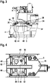
- connection between the hydraulic block 8 and the support frame 4 lies within the connection between the hydraulic tank 6 and the support frame 4, ie viewed in a plane which extends transversely to a top-bottom direction. Furthermore, according to figure 3 recognizable that connecting surfaces or flange surfaces between the hydraulic tank 6, the support frame 4 and the hydraulic block 8 extend approximately in a direction transverse to a top-bottom direction.
- the inner tank space of the hydraulic tank 6 can be seen, in which a cross-sectional view from below through the hydraulic tank 6 is shown.
- the hydraulic tank 6 has a U-shaped tank space 46 which is designed lying.
- two space legs 48 and 50 of the U-shaped tank space 46 extend approximately in a direction transverse to a top-bottom direction.
- the line 44 opens into the space leg 48.
- the frame-shaped configuration of the flange section 30 of the hydraulic tank 6 can be seen.
- the frame-shaped design of the flange connection 52 between the support frame 4 and the hydraulic block 8 can be seen.
- Another line 54 extends from the hydraulic block 8 into the space leg 50 of the hydraulic tank 6. This is used to remove oil from the hydraulic tank 6. It can also be seen that the tank space 46 is easily accessible via the passage opening 40 and the tank opening 32.
- the leveling foot 24 is shown. This has a plate 56 on the bottom side with a damping pad 58 between the plate 56 and a support surface 60.
- a bolt 60 which is screwed to the support frame 4, extends upwards from the plate 56.
- a device 64 is shown. This is part of a hydraulic press brake.
- the device 64 has a machine housing 66. This has two plate-shaped housing walls 68 and 70. These extend parallel to each other and in a top-to-bottom direction.
- Three connecting profiles 72, 74 and 76 are arranged between the housing walls 68, 70 in order to connect the housing walls 68, 70 to one another.
- the upper connecting profile 72 is U-shaped. Legs of the U-shaped connecting profile 72 extend upwards, so that a space accessible from above is delimited by the connecting profile 72 .
- the connecting web of the connecting profile 72 between the legs has the support surface 60, via which the hydraulic unit 1 and a hydraulic unit 78 of identical construction are supported. The units 1 and 78 point towards one another with their electric motors 16 .
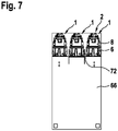
- FIG 7 A cross section through the machine housing 66 is shown.
- different possible positions of the hydraulic unit 1 are shown schematically.
- This can in accordance with figure 6 be arranged in the connection profile 72 or to the side of it if a corresponding support surface is formed.
- the arrangement of the hydraulic block 8 or the control 2 above the hydraulic tank 6 enables such a flexible arrangement, since the control 2 is accessible from the side and from above.
Landscapes
- Engineering & Computer Science (AREA)
- Mechanical Engineering (AREA)
- General Engineering & Computer Science (AREA)
- Physics & Mathematics (AREA)
- Fluid Mechanics (AREA)
- Supply Devices, Intensifiers, Converters, And Telemotors (AREA)
Applications Claiming Priority (1)
| Application Number | Priority Date | Filing Date | Title |
|---|---|---|---|
| DE102021203768.2A DE102021203768B4 (de) | 2021-04-16 | 2021-04-16 | Hydraulisches Aggregat und Vorrichtung mit dem Aggregat |
Publications (2)
| Publication Number | Publication Date |
|---|---|
| EP4074983A1 true EP4074983A1 (fr) | 2022-10-19 |
| EP4074983B1 EP4074983B1 (fr) | 2025-01-01 |
Family
ID=81307019
Family Applications (1)
| Application Number | Title | Priority Date | Filing Date |
|---|---|---|---|
| EP22167615.8A Active EP4074983B1 (fr) | 2021-04-16 | 2022-04-11 | Groupe hydraulique et dispositif pourvu de groupe |
Country Status (2)
| Country | Link |
|---|---|
| EP (1) | EP4074983B1 (fr) |
| DE (1) | DE102021203768B4 (fr) |
Cited By (1)
| Publication number | Priority date | Publication date | Assignee | Title |
|---|---|---|---|---|
| US20240240658A1 (en) * | 2023-01-17 | 2024-07-18 | Narendra Gupta | Hydraulic power pack module |
Citations (6)
| Publication number | Priority date | Publication date | Assignee | Title |
|---|---|---|---|---|
| JPS4995392U (fr) * | 1972-12-12 | 1974-08-16 | ||
| JPS49101186U (fr) * | 1972-12-22 | 1974-08-30 | ||
| JPS56148101U (fr) * | 1981-03-30 | 1981-11-07 | ||
| US20040134189A1 (en) * | 2003-01-09 | 2004-07-15 | Brigden Alex L | Computer monitored portable hydraulic power generation system |
| EP2251191A1 (fr) * | 2008-12-09 | 2010-11-17 | Robosoft N.V. | Procédé de contrôle du fonctionnement et de la sécurité d'une presse hydraulique, presse hydraulique qui fonctionne en fonction de ce procédé et utilisations du logiciel et support appliqué à celle-ci |
| DE102018218113A1 (de) | 2018-10-23 | 2020-04-23 | Robert Bosch Gmbh | Hydraulische Steueranordnung |
Family Cites Families (1)
| Publication number | Priority date | Publication date | Assignee | Title |
|---|---|---|---|---|
| DE102004032256B3 (de) | 2004-07-03 | 2005-12-15 | Jungheinrich Ag | Hydraulikaggregat für Flurförderzeuge |
-
2021
- 2021-04-16 DE DE102021203768.2A patent/DE102021203768B4/de active Active
-
2022
- 2022-04-11 EP EP22167615.8A patent/EP4074983B1/fr active Active
Patent Citations (6)
| Publication number | Priority date | Publication date | Assignee | Title |
|---|---|---|---|---|
| JPS4995392U (fr) * | 1972-12-12 | 1974-08-16 | ||
| JPS49101186U (fr) * | 1972-12-22 | 1974-08-30 | ||
| JPS56148101U (fr) * | 1981-03-30 | 1981-11-07 | ||
| US20040134189A1 (en) * | 2003-01-09 | 2004-07-15 | Brigden Alex L | Computer monitored portable hydraulic power generation system |
| EP2251191A1 (fr) * | 2008-12-09 | 2010-11-17 | Robosoft N.V. | Procédé de contrôle du fonctionnement et de la sécurité d'une presse hydraulique, presse hydraulique qui fonctionne en fonction de ce procédé et utilisations du logiciel et support appliqué à celle-ci |
| DE102018218113A1 (de) | 2018-10-23 | 2020-04-23 | Robert Bosch Gmbh | Hydraulische Steueranordnung |
Cited By (1)
| Publication number | Priority date | Publication date | Assignee | Title |
|---|---|---|---|---|
| US20240240658A1 (en) * | 2023-01-17 | 2024-07-18 | Narendra Gupta | Hydraulic power pack module |
Also Published As
| Publication number | Publication date |
|---|---|
| EP4074983B1 (fr) | 2025-01-01 |
| DE102021203768B4 (de) | 2022-11-10 |
| DE102021203768A1 (de) | 2022-10-20 |
Similar Documents
| Publication | Publication Date | Title |
|---|---|---|
| DE102008053583A1 (de) | Einspritzdüsenhalterungsstruktur | |
| EP2153031B1 (fr) | Carter d'huile pour une unité moteur à combustion interne- boite de vitesses | |
| DE102021203768B4 (de) | Hydraulisches Aggregat und Vorrichtung mit dem Aggregat | |
| EP1870324A2 (fr) | Châssis à chaîne | |
| DE3520876C1 (de) | Vorrichtung zum Zuführen von Schmieröl zu den Reibstellen einer Nockenwelle | |
| DE112018003943B4 (de) | Hydraulische Karosseriehalterung | |
| EP3320210B1 (fr) | Groupe hydraulique | |
| EP2943697B1 (fr) | Frein à disque pour véhicule utilitaire | |
| DE102018005306B4 (de) | Kopplungsvorrichtung für einen Bremsfluidbehälter und Fahrzeugbremsanlage | |
| AT405631B (de) | Betätigungsanordnung für bewegliche teile an fahrzeugen, insbesondere für heckdeckel, verdeck-abdeckungen od. dgl. | |
| EP4074984A1 (fr) | Bloc hydraulique et procédé | |
| EP1514020A1 (fr) | Culasse de moteur a combustion interne a piston alternatif | |
| DE102008013235B4 (de) | Vorrichtung zum dosierten Ausgeben einer Schmierflüssigkeit | |
| WO2002028682A1 (fr) | Reservoir a liquides | |
| EP0724080B1 (fr) | Système d'actionnement hydraulique pour hayon élévateur ou similaire, en particulier pour véhicules automobiles | |
| DE29813031U1 (de) | Federvorrichtung | |
| WO2023161089A1 (fr) | Amortisseur de vibrations doté d'un raccordement à un système hydraulique | |
| EP3030784B1 (fr) | Pompe volumétrique | |
| EP4126625B1 (fr) | Véhicule ferroviaire équipé d'un compresseur | |
| DE102008048608A1 (de) | Bodenkonstruktion für Schienenfahrzeuge | |
| EP3707050A1 (fr) | Système de réglage de niveau pour régler le niveau d'un véhicule, notamment d'un véhicule ferroviaire | |
| DE2165350A1 (de) | Ölhydraulische Presse mit kastenförmigem Säulengestell | |
| DE20007465U1 (de) | System zum Auffangen von Verunreinigungen, insbesondere im Gleisbereich unterhalb von Schienenfahrzeugen, sowie Halterung hierfür | |
| DE102023205960A1 (de) | Kompressorgehäuse, integriertes System, integrierte Wärmepumpe, Fahrzeug und Herstellungsverfahren für Kompressorgehäuse | |
| WO2018068970A1 (fr) | Boîtier de commande pour un actionneur d'embrayage |
Legal Events
| Date | Code | Title | Description |
|---|---|---|---|
| PUAI | Public reference made under article 153(3) epc to a published international application that has entered the european phase |
Free format text: ORIGINAL CODE: 0009012 |
|
| STAA | Information on the status of an ep patent application or granted ep patent |
Free format text: STATUS: THE APPLICATION HAS BEEN PUBLISHED |
|
| AK | Designated contracting states |
Kind code of ref document: A1 Designated state(s): AL AT BE BG CH CY CZ DE DK EE ES FI FR GB GR HR HU IE IS IT LI LT LU LV MC MK MT NL NO PL PT RO RS SE SI SK SM TR |
|
| STAA | Information on the status of an ep patent application or granted ep patent |
Free format text: STATUS: REQUEST FOR EXAMINATION WAS MADE |
|
| 17P | Request for examination filed |
Effective date: 20230419 |
|
| RBV | Designated contracting states (corrected) |
Designated state(s): AL AT BE BG CH CY CZ DE DK EE ES FI FR GB GR HR HU IE IS IT LI LT LU LV MC MK MT NL NO PL PT RO RS SE SI SK SM TR |
|
| STAA | Information on the status of an ep patent application or granted ep patent |
Free format text: STATUS: EXAMINATION IS IN PROGRESS |
|
| 17Q | First examination report despatched |
Effective date: 20240213 |
|
| GRAP | Despatch of communication of intention to grant a patent |
Free format text: ORIGINAL CODE: EPIDOSNIGR1 |
|
| STAA | Information on the status of an ep patent application or granted ep patent |
Free format text: STATUS: GRANT OF PATENT IS INTENDED |
|
| INTG | Intention to grant announced |
Effective date: 20241011 |
|
| GRAS | Grant fee paid |
Free format text: ORIGINAL CODE: EPIDOSNIGR3 |
|
| GRAA | (expected) grant |
Free format text: ORIGINAL CODE: 0009210 |
|
| STAA | Information on the status of an ep patent application or granted ep patent |
Free format text: STATUS: THE PATENT HAS BEEN GRANTED |
|
| AK | Designated contracting states |
Kind code of ref document: B1 Designated state(s): AL AT BE BG CH CY CZ DE DK EE ES FI FR GB GR HR HU IE IS IT LI LT LU LV MC MK MT NL NO PL PT RO RS SE SI SK SM TR |
|
| REG | Reference to a national code |
Ref country code: GB Ref legal event code: FG4D Free format text: NOT ENGLISH |
|
| REG | Reference to a national code |
Ref country code: DE Ref legal event code: R096 Ref document number: 502022002545 Country of ref document: DE |
|
| REG | Reference to a national code |
Ref country code: CH Ref legal event code: EP |
|
| REG | Reference to a national code |
Ref country code: IE Ref legal event code: FG4D Free format text: LANGUAGE OF EP DOCUMENT: GERMAN |
|
| REG | Reference to a national code |
Ref country code: LT Ref legal event code: MG9D |
|
| REG | Reference to a national code |
Ref country code: NL Ref legal event code: MP Effective date: 20250101 |
|
| PG25 | Lapsed in a contracting state [announced via postgrant information from national office to epo] |
Ref country code: NL Free format text: LAPSE BECAUSE OF FAILURE TO SUBMIT A TRANSLATION OF THE DESCRIPTION OR TO PAY THE FEE WITHIN THE PRESCRIBED TIME-LIMIT Effective date: 20250101 |
|
| PG25 | Lapsed in a contracting state [announced via postgrant information from national office to epo] |
Ref country code: FI Free format text: LAPSE BECAUSE OF FAILURE TO SUBMIT A TRANSLATION OF THE DESCRIPTION OR TO PAY THE FEE WITHIN THE PRESCRIBED TIME-LIMIT Effective date: 20250101 |
|
| PG25 | Lapsed in a contracting state [announced via postgrant information from national office to epo] |
Ref country code: PL Free format text: LAPSE BECAUSE OF FAILURE TO SUBMIT A TRANSLATION OF THE DESCRIPTION OR TO PAY THE FEE WITHIN THE PRESCRIBED TIME-LIMIT Effective date: 20250101 |
|
| PGFP | Annual fee paid to national office [announced via postgrant information from national office to epo] |
Ref country code: DE Payment date: 20250624 Year of fee payment: 4 |
|
| PG25 | Lapsed in a contracting state [announced via postgrant information from national office to epo] |
Ref country code: ES Free format text: LAPSE BECAUSE OF FAILURE TO SUBMIT A TRANSLATION OF THE DESCRIPTION OR TO PAY THE FEE WITHIN THE PRESCRIBED TIME-LIMIT Effective date: 20250101 |
|
| PG25 | Lapsed in a contracting state [announced via postgrant information from national office to epo] |
Ref country code: NO Free format text: LAPSE BECAUSE OF FAILURE TO SUBMIT A TRANSLATION OF THE DESCRIPTION OR TO PAY THE FEE WITHIN THE PRESCRIBED TIME-LIMIT Effective date: 20250401 Ref country code: IS Free format text: LAPSE BECAUSE OF FAILURE TO SUBMIT A TRANSLATION OF THE DESCRIPTION OR TO PAY THE FEE WITHIN THE PRESCRIBED TIME-LIMIT Effective date: 20250501 |
|
| PG25 | Lapsed in a contracting state [announced via postgrant information from national office to epo] |
Ref country code: HR Free format text: LAPSE BECAUSE OF FAILURE TO SUBMIT A TRANSLATION OF THE DESCRIPTION OR TO PAY THE FEE WITHIN THE PRESCRIBED TIME-LIMIT Effective date: 20250101 |
|
| PG25 | Lapsed in a contracting state [announced via postgrant information from national office to epo] |
Ref country code: LV Free format text: LAPSE BECAUSE OF FAILURE TO SUBMIT A TRANSLATION OF THE DESCRIPTION OR TO PAY THE FEE WITHIN THE PRESCRIBED TIME-LIMIT Effective date: 20250101 Ref country code: PT Free format text: LAPSE BECAUSE OF FAILURE TO SUBMIT A TRANSLATION OF THE DESCRIPTION OR TO PAY THE FEE WITHIN THE PRESCRIBED TIME-LIMIT Effective date: 20250502 |
|
| PG25 | Lapsed in a contracting state [announced via postgrant information from national office to epo] |
Ref country code: BG Free format text: LAPSE BECAUSE OF FAILURE TO SUBMIT A TRANSLATION OF THE DESCRIPTION OR TO PAY THE FEE WITHIN THE PRESCRIBED TIME-LIMIT Effective date: 20250101 Ref country code: GR Free format text: LAPSE BECAUSE OF FAILURE TO SUBMIT A TRANSLATION OF THE DESCRIPTION OR TO PAY THE FEE WITHIN THE PRESCRIBED TIME-LIMIT Effective date: 20250402 |
|
| PGFP | Annual fee paid to national office [announced via postgrant information from national office to epo] |
Ref country code: AT Payment date: 20250721 Year of fee payment: 4 |
|
| PGFP | Annual fee paid to national office [announced via postgrant information from national office to epo] |
Ref country code: TR Payment date: 20250404 Year of fee payment: 4 |
|
| PG25 | Lapsed in a contracting state [announced via postgrant information from national office to epo] |
Ref country code: CZ Free format text: LAPSE BECAUSE OF FAILURE TO SUBMIT A TRANSLATION OF THE DESCRIPTION OR TO PAY THE FEE WITHIN THE PRESCRIBED TIME-LIMIT Effective date: 20250101 |
|
| PG25 | Lapsed in a contracting state [announced via postgrant information from national office to epo] |
Ref country code: SE Free format text: LAPSE BECAUSE OF FAILURE TO SUBMIT A TRANSLATION OF THE DESCRIPTION OR TO PAY THE FEE WITHIN THE PRESCRIBED TIME-LIMIT Effective date: 20250101 |
|
| REG | Reference to a national code |
Ref country code: DE Ref legal event code: R097 Ref document number: 502022002545 Country of ref document: DE |
|
| PG25 | Lapsed in a contracting state [announced via postgrant information from national office to epo] |
Ref country code: SM Free format text: LAPSE BECAUSE OF FAILURE TO SUBMIT A TRANSLATION OF THE DESCRIPTION OR TO PAY THE FEE WITHIN THE PRESCRIBED TIME-LIMIT Effective date: 20250101 |
|
| PG25 | Lapsed in a contracting state [announced via postgrant information from national office to epo] |
Ref country code: DK Free format text: LAPSE BECAUSE OF FAILURE TO SUBMIT A TRANSLATION OF THE DESCRIPTION OR TO PAY THE FEE WITHIN THE PRESCRIBED TIME-LIMIT Effective date: 20250101 |
|
| PG25 | Lapsed in a contracting state [announced via postgrant information from national office to epo] |
Ref country code: IT Free format text: LAPSE BECAUSE OF FAILURE TO SUBMIT A TRANSLATION OF THE DESCRIPTION OR TO PAY THE FEE WITHIN THE PRESCRIBED TIME-LIMIT Effective date: 20250101 |
|
| PG25 | Lapsed in a contracting state [announced via postgrant information from national office to epo] |
Ref country code: EE Free format text: LAPSE BECAUSE OF FAILURE TO SUBMIT A TRANSLATION OF THE DESCRIPTION OR TO PAY THE FEE WITHIN THE PRESCRIBED TIME-LIMIT Effective date: 20250101 |
|
| PG25 | Lapsed in a contracting state [announced via postgrant information from national office to epo] |
Ref country code: RO Free format text: LAPSE BECAUSE OF FAILURE TO SUBMIT A TRANSLATION OF THE DESCRIPTION OR TO PAY THE FEE WITHIN THE PRESCRIBED TIME-LIMIT Effective date: 20250101 |
|
| PG25 | Lapsed in a contracting state [announced via postgrant information from national office to epo] |
Ref country code: SK Free format text: LAPSE BECAUSE OF FAILURE TO SUBMIT A TRANSLATION OF THE DESCRIPTION OR TO PAY THE FEE WITHIN THE PRESCRIBED TIME-LIMIT Effective date: 20250101 |
|
| PLBE | No opposition filed within time limit |
Free format text: ORIGINAL CODE: 0009261 |
|
| STAA | Information on the status of an ep patent application or granted ep patent |
Free format text: STATUS: NO OPPOSITION FILED WITHIN TIME LIMIT |
|
| REG | Reference to a national code |
Ref country code: CH Ref legal event code: L10 Free format text: ST27 STATUS EVENT CODE: U-0-0-L10-L00 (AS PROVIDED BY THE NATIONAL OFFICE) Effective date: 20251112 |
|
| REG | Reference to a national code |
Ref country code: CH Ref legal event code: H13 Free format text: ST27 STATUS EVENT CODE: U-0-0-H10-H13 (AS PROVIDED BY THE NATIONAL OFFICE) Effective date: 20251125 |
|
| 26N | No opposition filed |
Effective date: 20251002 |
|
| PG25 | Lapsed in a contracting state [announced via postgrant information from national office to epo] |
Ref country code: LU Free format text: LAPSE BECAUSE OF NON-PAYMENT OF DUE FEES Effective date: 20250411 |
|
| PG25 | Lapsed in a contracting state [announced via postgrant information from national office to epo] |
Ref country code: MC Free format text: LAPSE BECAUSE OF FAILURE TO SUBMIT A TRANSLATION OF THE DESCRIPTION OR TO PAY THE FEE WITHIN THE PRESCRIBED TIME-LIMIT Effective date: 20250101 |
|
| REG | Reference to a national code |
Ref country code: BE Ref legal event code: MM Effective date: 20250430 |
|
| PG25 | Lapsed in a contracting state [announced via postgrant information from national office to epo] |
Ref country code: FR Free format text: LAPSE BECAUSE OF NON-PAYMENT OF DUE FEES Effective date: 20250430 |
|
| PG25 | Lapsed in a contracting state [announced via postgrant information from national office to epo] |
Ref country code: BE Free format text: LAPSE BECAUSE OF NON-PAYMENT OF DUE FEES Effective date: 20250430 |
|
| PG25 | Lapsed in a contracting state [announced via postgrant information from national office to epo] |
Ref country code: CH Free format text: LAPSE BECAUSE OF NON-PAYMENT OF DUE FEES Effective date: 20250430 |
|
| PG25 | Lapsed in a contracting state [announced via postgrant information from national office to epo] |
Ref country code: IE Free format text: LAPSE BECAUSE OF NON-PAYMENT OF DUE FEES Effective date: 20250411 |