EP4076140B1 - Ophtalmoscope destinée à l'examen des yeux - Google Patents
Ophtalmoscope destinée à l'examen des yeux Download PDFInfo
- Publication number
- EP4076140B1 EP4076140B1 EP20817207.2A EP20817207A EP4076140B1 EP 4076140 B1 EP4076140 B1 EP 4076140B1 EP 20817207 A EP20817207 A EP 20817207A EP 4076140 B1 EP4076140 B1 EP 4076140B1
- Authority
- EP
- European Patent Office
- Prior art keywords
- eye
- lens
- image
- ophthalmoscope
- conversion
- Prior art date
- Legal status (The legal status is an assumption and is not a legal conclusion. Google has not performed a legal analysis and makes no representation as to the accuracy of the status listed.)
- Active
Links
Images





Classifications
-
- A—HUMAN NECESSITIES
- A61—MEDICAL OR VETERINARY SCIENCE; HYGIENE
- A61B—DIAGNOSIS; SURGERY; IDENTIFICATION
- A61B3/00—Apparatus for testing the eyes; Instruments for examining the eyes
- A61B3/10—Objective types, i.e. instruments for examining the eyes independent of the patients' perceptions or reactions
- A61B3/12—Objective types, i.e. instruments for examining the eyes independent of the patients' perceptions or reactions for looking at the eye fundus, e.g. ophthalmoscopes
-
- A—HUMAN NECESSITIES
- A61—MEDICAL OR VETERINARY SCIENCE; HYGIENE
- A61B—DIAGNOSIS; SURGERY; IDENTIFICATION
- A61B3/00—Apparatus for testing the eyes; Instruments for examining the eyes
- A61B3/10—Objective types, i.e. instruments for examining the eyes independent of the patients' perceptions or reactions
-
- A—HUMAN NECESSITIES
- A61—MEDICAL OR VETERINARY SCIENCE; HYGIENE
- A61B—DIAGNOSIS; SURGERY; IDENTIFICATION
- A61B3/00—Apparatus for testing the eyes; Instruments for examining the eyes
- A61B3/10—Objective types, i.e. instruments for examining the eyes independent of the patients' perceptions or reactions
- A61B3/14—Arrangements specially adapted for eye photography
-
- A—HUMAN NECESSITIES
- A61—MEDICAL OR VETERINARY SCIENCE; HYGIENE
- A61B—DIAGNOSIS; SURGERY; IDENTIFICATION
- A61B1/00—Instruments for performing medical examinations of the interior of cavities or tubes of the body by visual or photographical inspection, e.g. endoscopes; Illuminating arrangements therefor
- A61B1/005—Flexible endoscopes
- A61B1/01—Guiding arrangements therefore
-
- A—HUMAN NECESSITIES
- A61—MEDICAL OR VETERINARY SCIENCE; HYGIENE
- A61B—DIAGNOSIS; SURGERY; IDENTIFICATION
- A61B3/00—Apparatus for testing the eyes; Instruments for examining the eyes
- A61B3/0008—Apparatus for testing the eyes; Instruments for examining the eyes provided with illuminating means
-
- A—HUMAN NECESSITIES
- A61—MEDICAL OR VETERINARY SCIENCE; HYGIENE
- A61B—DIAGNOSIS; SURGERY; IDENTIFICATION
- A61B3/00—Apparatus for testing the eyes; Instruments for examining the eyes
- A61B3/0083—Apparatus for testing the eyes; Instruments for examining the eyes provided with means for patient positioning
-
- A—HUMAN NECESSITIES
- A61—MEDICAL OR VETERINARY SCIENCE; HYGIENE
- A61B—DIAGNOSIS; SURGERY; IDENTIFICATION
- A61B3/00—Apparatus for testing the eyes; Instruments for examining the eyes
- A61B3/10—Objective types, i.e. instruments for examining the eyes independent of the patients' perceptions or reactions
- A61B3/107—Objective types, i.e. instruments for examining the eyes independent of the patients' perceptions or reactions for determining the shape or measuring the curvature of the cornea
-
- A—HUMAN NECESSITIES
- A61—MEDICAL OR VETERINARY SCIENCE; HYGIENE
- A61B—DIAGNOSIS; SURGERY; IDENTIFICATION
- A61B3/00—Apparatus for testing the eyes; Instruments for examining the eyes
- A61B3/10—Objective types, i.e. instruments for examining the eyes independent of the patients' perceptions or reactions
- A61B3/113—Objective types, i.e. instruments for examining the eyes independent of the patients' perceptions or reactions for determining or recording eye movement
-
- A—HUMAN NECESSITIES
- A61—MEDICAL OR VETERINARY SCIENCE; HYGIENE
- A61B—DIAGNOSIS; SURGERY; IDENTIFICATION
- A61B3/00—Apparatus for testing the eyes; Instruments for examining the eyes
- A61B3/10—Objective types, i.e. instruments for examining the eyes independent of the patients' perceptions or reactions
- A61B3/12—Objective types, i.e. instruments for examining the eyes independent of the patients' perceptions or reactions for looking at the eye fundus, e.g. ophthalmoscopes
- A61B3/1216—Objective types, i.e. instruments for examining the eyes independent of the patients' perceptions or reactions for looking at the eye fundus, e.g. ophthalmoscopes for diagnostics of the iris
-
- A—HUMAN NECESSITIES
- A61—MEDICAL OR VETERINARY SCIENCE; HYGIENE
- A61B—DIAGNOSIS; SURGERY; IDENTIFICATION
- A61B3/00—Apparatus for testing the eyes; Instruments for examining the eyes
- A61B3/10—Objective types, i.e. instruments for examining the eyes independent of the patients' perceptions or reactions
- A61B3/12—Objective types, i.e. instruments for examining the eyes independent of the patients' perceptions or reactions for looking at the eye fundus, e.g. ophthalmoscopes
- A61B3/1241—Objective types, i.e. instruments for examining the eyes independent of the patients' perceptions or reactions for looking at the eye fundus, e.g. ophthalmoscopes specially adapted for observation of ocular blood flow, e.g. by fluorescein angiography
-
- A—HUMAN NECESSITIES
- A61—MEDICAL OR VETERINARY SCIENCE; HYGIENE
- A61B—DIAGNOSIS; SURGERY; IDENTIFICATION
- A61B3/00—Apparatus for testing the eyes; Instruments for examining the eyes
- A61B3/10—Objective types, i.e. instruments for examining the eyes independent of the patients' perceptions or reactions
- A61B3/12—Objective types, i.e. instruments for examining the eyes independent of the patients' perceptions or reactions for looking at the eye fundus, e.g. ophthalmoscopes
- A61B3/125—Objective types, i.e. instruments for examining the eyes independent of the patients' perceptions or reactions for looking at the eye fundus, e.g. ophthalmoscopes with contact lenses
-
- A—HUMAN NECESSITIES
- A61—MEDICAL OR VETERINARY SCIENCE; HYGIENE
- A61B—DIAGNOSIS; SURGERY; IDENTIFICATION
- A61B3/00—Apparatus for testing the eyes; Instruments for examining the eyes
- A61B3/10—Objective types, i.e. instruments for examining the eyes independent of the patients' perceptions or reactions
- A61B3/13—Ophthalmic microscopes
-
- A—HUMAN NECESSITIES
- A61—MEDICAL OR VETERINARY SCIENCE; HYGIENE
- A61B—DIAGNOSIS; SURGERY; IDENTIFICATION
- A61B3/00—Apparatus for testing the eyes; Instruments for examining the eyes
- A61B3/10—Objective types, i.e. instruments for examining the eyes independent of the patients' perceptions or reactions
- A61B3/13—Ophthalmic microscopes
- A61B3/132—Ophthalmic microscopes in binocular arrangement
-
- G—PHYSICS
- G01—MEASURING; TESTING
- G01N—INVESTIGATING OR ANALYSING MATERIALS BY DETERMINING THEIR CHEMICAL OR PHYSICAL PROPERTIES
- G01N21/00—Investigating or analysing materials by the use of optical means, i.e. using sub-millimetre waves, infrared, visible or ultraviolet light
- G01N21/62—Systems in which the material investigated is excited whereby it emits light or causes a change in wavelength of the incident light
- G01N21/63—Systems in which the material investigated is excited whereby it emits light or causes a change in wavelength of the incident light optically excited
- G01N21/64—Fluorescence; Phosphorescence
-
- G—PHYSICS
- G02—OPTICS
- G02B—OPTICAL ELEMENTS, SYSTEMS OR APPARATUS
- G02B13/00—Optical objectives specially designed for the purposes specified below
- G02B13/16—Optical objectives specially designed for the purposes specified below for use in conjunction with image converters or intensifiers, or for use with projectors, e.g. objectives for projection TV
-
- G—PHYSICS
- G02—OPTICS
- G02B—OPTICAL ELEMENTS, SYSTEMS OR APPARATUS
- G02B13/00—Optical objectives specially designed for the purposes specified below
- G02B13/18—Optical objectives specially designed for the purposes specified below with lenses having one or more non-spherical faces, e.g. for reducing geometrical aberration
-
- A—HUMAN NECESSITIES
- A61—MEDICAL OR VETERINARY SCIENCE; HYGIENE
- A61B—DIAGNOSIS; SURGERY; IDENTIFICATION
- A61B3/00—Apparatus for testing the eyes; Instruments for examining the eyes
- A61B3/10—Objective types, i.e. instruments for examining the eyes independent of the patients' perceptions or reactions
- A61B3/13—Ophthalmic microscopes
- A61B3/135—Slit-lamp microscopes
-
- A—HUMAN NECESSITIES
- A61—MEDICAL OR VETERINARY SCIENCE; HYGIENE
- A61B—DIAGNOSIS; SURGERY; IDENTIFICATION
- A61B3/00—Apparatus for testing the eyes; Instruments for examining the eyes
- A61B3/10—Objective types, i.e. instruments for examining the eyes independent of the patients' perceptions or reactions
- A61B3/14—Arrangements specially adapted for eye photography
- A61B3/15—Arrangements specially adapted for eye photography with means for aligning, spacing or blocking spurious reflection ; with means for relaxing
-
- G—PHYSICS
- G02—OPTICS
- G02B—OPTICAL ELEMENTS, SYSTEMS OR APPARATUS
- G02B17/00—Systems with reflecting surfaces, with or without refracting elements
- G02B17/08—Catadioptric systems
-
- G—PHYSICS
- G06—COMPUTING OR CALCULATING; COUNTING
- G06T—IMAGE DATA PROCESSING OR GENERATION, IN GENERAL
- G06T2207/00—Indexing scheme for image analysis or image enhancement
- G06T2207/30—Subject of image; Context of image processing
- G06T2207/30004—Biomedical image processing
- G06T2207/30041—Eye; Retina; Ophthalmic
Definitions
- the invention relates to an ophthalmoscope for examining a visible surface of eyes, comprising a housing, at least one device for converting light into an electrical signal in the form of a planar chip and at least one objective, wherein the at least one objective comprises at least one lens and/or at least one mirror.
- the invention further relates to such an ophthalmoscope with a slit lamp and to the use of such an ophthalmoscope on the human eye.
- the invention further relates to a method for examining eyes using such an ophthalmoscope and to an ophthalmoscope with a computer program product.
- ophthalmoscopes which usually examine eyes using a slit lamp, can only focus on one plane. Since a complex eye geometry deviates from a plane, it is only possible to image a ring zone of the eye sharply on the device for conversion, especially when the eye is magnified tenfold, with the remaining surface of the eye being imaged blurry by commercially available ophthalmoscopes. These ophthalmoscopes are unsuitable for efficient and effective eye examination and since a large number of images are necessary for a complete sharp image of the eye, each of which only sharply images one area of the eye, the eye would have to be positioned exactly the same over a period of time for all images, which corresponds to an ideal that is practically impossible to implement.
- a system for the inspection of an ophthalmic lens is already known from the document US6,577,387 B2 known in which changes in an intensity of light of an image on a device for converting light - caused by changes in a thickness of the ophthalmic lens - are analyzed.
- the changes in the thickness of the ophthalmic lens are caused by cosmetic defects, irregularities or by a design of the ophthalmic lens.
- An imaging lens arrangement in the form of an objective may have a curved focal surface in order to generate an improvement in focus with respect to the curvature of the ophthalmic lens.
- a disadvantage of the state of the art is that the inspection of ophthalmic lenses is carried out using an absorption technique taking into account the Lambert-Beer principle for ophthalmic lenses and cannot be used for the examination of eyes with a complex convex geometry, which is different from an ophthalmic lens.
- the absorption technique uses light with wavelengths in the ultraviolet range, in the infrared range or laser light with monochromatic light, which, given the performance required for the absorption technique, cannot be used for the examination of eyes for health reasons. are unsuitable. For visible light, additional optical elements for manipulating light would be required in order to be able to examine the inspection of the ophthalmic lenses using the absorption technique.
- the objective technical task of the present invention is therefore to provide an ophthalmoscope which is improved compared to the prior art, in which the disadvantages of the prior art are at least partially eliminated, and which is characterized in particular by a reduced aberration and enables reproducible and comparable images of the eye.
- the at least one lens has a convex curved Has a focus area, wherein a convexly curved image area of an eye can be sharply imaged through the at least one lens onto the at least one conversion device, wherein the entire visible area of the eye can be sharply imaged onto the at least one conversion device and wherein the ophthalmoscope comprises pulsed illumination.
- focal area of a lens refers to the area that is generated by the lens when an object plane is projected.
- the focal area can be used to display an image area of an object surface in a modified way on a conversion device. If the object surface is convexly curved, the image surface is also convexly curved without a lens arrangement.
- the convexly curved image surface is changed by a convexly curved focus area of the lens arrangement. A more convexly curved image surface can thus be transformed into a less convexly curved image surface.
- object surface describes the surface geometry of an object, whereby, in contrast to a flat object plane, in this generalization, a curvature in the surface geometry of the object can be present.
- image surface describes the surface geometry of the image of the object, whereby, in contrast to a flat image plane, in this generalization, a curvature in the surface geometry of the image of the object can be present. This Viewing is not limited to lenses with optical elements.
- sharp is defined in this context of ophthalmoscopy to mean that the image of an object has a high resolution, with a contrast of a line pair between separate, adjacent pixels on the at least one conversion device of at least 20%, more advantageously at least 30%.
- geometric optics only those points of the object which lie on an image plane that are within an object distance or object distance to the lens can be reproduced as sharp image points in the conversion device. If the image plane is a convexly curved image surface, because the object surface of the object is also convexly curved, an arrangement of lenses must compensate for the curvature of the image surface in order to be able to generate a sharp image of the object on the conversion device.
- the convexly curved focus surface of the at least one lens makes it possible to project complex convex geometries of an eye in the visible wavelength range of light sharply onto the at least one conversion device, wherein the sharp image on the at least one conversion device can be adapted to the given surface geometry of the at least one conversion device by the convexly curved focus surface.
- the convexly curved focus surface of the at least one lens can be individually adapted to the conditions of a specific eye geometry, whereby the entire surface of the eye visible to the at least one lens can be sharply imaged onto the at least one conversion device.
- the entire visible area of the eye can be sharply imaged on the at least one conversion device, a standardization of images of the eye and a comparison of a large number of images of the eye are also made possible, and categorization based on eye-specific characteristics can be carried out. This significantly facilitates analysis of the image of the eye. Bidirectional measurements on the image of the eye are also made possible, which would not be possible by imaging a ring zone of the eye.
- the ophthalmoscope with at least one lens comprises at least one mirror, it is a so-called catadioptric system, whereby the at least one mirror particularly promotes the sharp image of the eye.
- the at least one mirror can, for example, be a freeform mirror.
- ophthalmoscopes in which at least one objective is formed only by mirrors and does not require any lenses.
- beam paths from the eye to the at least one conversion device can be manipulated in a particularly advantageous manner in order to improve a sharp image of the eye.
- both eyes can be imaged synchronously or simultaneously in stereo using the ophthalmoscope.
- protection is also required for the ophthalmoscope with a slit lamp. Protection is also required for the use of the ophthalmoscope on the human eye.
- the autofocus algorithm can perform contrast optimization and/or position measurement, whereby the position measurement for example, by using a lateral camera to capture a vertex of the eye as a line or a distance measurement can be carried out, e.g. using a laser.
- protection is also sought for such an ophthalmoscope with a computer program product comprising instructions which, when executed by a computing unit, cause the ophthalmoscope to examine eyes to classify at least one image of an eye from a storage unit which is in a data connection with the computing unit or can be brought into such a connection, wherein a classification is generated based on a blood vessel structure and/or a corneal structure and/or a scar structure and/or an eye socket structure.
- a blood vessel structure can be an indicator of redness of the eye and/or dryness of the eye.
- the chip is designed as a CMOS sensor.
- the chip can be a CCD sensor, for example.
- the chip is particularly preferably in the form of a CMOS sensor.
- the CMOS sensor comprises complementary metal oxide semiconductor components (complementary metal-oxide-semiconductors) and can be an active pixel sensor or a passive pixel sensor.
- an image of the eye can be conveniently read out within a very short time and made available for storage, thereby increasing the possible number of images of the eye to be recorded by the at least one conversion device per time interval.
- the time per image of the eye through the ophthalmoscope can be further reduced.
- high brightness can be achieved without blinding the patient.
- image noise is reduced.
- the at least one conversion device comprises at least one Bayer filter.
- Bayer filter describes a color filter in which the three primary colors red, green and blue and, if applicable, the color white are arranged in the form of pixels in a checkerboard structure.
- At least one Bayer filter enables the at least one conversion device to particularly efficiently record color information from the image of the eye.
- the at least one Bayer filter can generate a division into red, green and blue pixels. Broadband light with a half-width in the range of 70 nm to 130 nm is preferably passed through the Bayer filter. Maxima of a quantum efficiency of the Bayer filter are in the range between 450-455 nm for blue, 535-545 nm for green and 610-615 nm for red pixels.
- At least two lenses are designed in the form of at least one air lens, wherein a Petzval sum of the at least one air lens is negative.
- the term air lens describes a lens arrangement that has a negative Petzval sum.
- the Petzval sum corresponds to a reciprocal radius of a Petzval surface, whereby the reciprocal radius of the Petzval surface is defined by the sum of all reciprocals of the refractive indices of the (thin) lenses involved multiplied by the respective focal length of the lens in the beam direction.
- At least one air lens enables an imaging of a convex curved surface onto a planar surface with an objective comprising a smaller number of lenses.
- the imaging of the eye with a complex geometry which can be caused, for example, by variable radii of curvature, is particularly favored.
- the exact numerical value of the Petzval sum required for imaging a convexly curved surface onto a planar surface can be calculated, for example, via the additional lenses in the lens or distances between the at least one conversion device and the object to be imaged, whereby the refractive indices and the focal lengths of the lens can be adapted to the requirements of the ophthalmoscope.
- a gas mixture with a refractive index of less than 1.3, preferably less than 1.1 is arranged within the at least one air lens, wherein it is preferably provided that the gas mixture contains at least one noble gas, particularly preferably argon, nitrogen and/or air, particularly preferably in the form of the noble gas, nitrogen or air.
- lens arrangements are also possible which have a Petzval sum with the required value via gel, liquid and/or rubber-based inclusions.
- a gas mixture is particularly preferably completely enclosed by the at least two lenses, with air having proven to be particularly effective and cost-effective due to its low refractive index and high availability, whereby a particularly compact ophthalmoscope can be formed.
- other gas mixtures in the at least one air lens are also conceivable.
- a lens-shaped Fluid inclusion is arranged, wherein the Petzval sum of the sensor-side lens, the object-side lens and the fluid inclusion is negative.
- the refractive index of the at least one fluid inclusion can be easily and cost-effectively adjusted by the composition of a fluid, a high degree of flexibility is possible with regard to the requirements for the at least one objective.
- the refractive index of a fluid such as air is usually much lower than the refractive index of lens materials such as optical glass, which means that the Petzval sum of a lens arrangement can be set to a negative value particularly efficiently and/or with little material expenditure.
- the at least one air lens is designed such that a lens with a first refractive index is arranged on the object side and a lens with a second refractive index is arranged on the sensor side, wherein the second refractive index is higher than the first refractive index and/or the at least one air lens is designed to be biconvex.
- a combination of focal lengths is particularly favorable for a negative Petzval sum.
- the first refractive index is lower than the second refractive index, this can be reflected in terms of negative terms in the Petzval sum have a beneficial effect on the ophthalmoscope.
- An advantageous variant consists in having exactly two air lenses spaced apart from each other.
- the at least one objective and/or an object-side image and/or an object-side beam path is designed to be substantially telecentric, preferably pericentric.
- an image on the at least one conversion device is displayed in color.
- the user of the ophthalmoscope can better recognize fine structures of the eye.
- the numerical aperture indicates the ability of an optical element to focus light.
- the numerical aperture is the product of the sine of half the object-side aperture angle and the refractive index of a material between the lens and a focus.
- the sensor-side numerical aperture in the range of 0.04 to 0.1 enables an ophthalmoscope resolution that is not affected by diffraction phenomena.
- the at least one lens has an aperture, wherein the aperture has a radius in the range of 2.5 mm to 3.5 mm, preferably in the range of 2.9 to 3.3.
- a particularly preferred device for conversion comprises a resolution in the range of 4.88 ⁇ m. This is made possible by an aperture radius between 2.5 mm and 3.5 mm.
- the ophthalmoscope comprises exactly eight lenses and/or exactly two plane disks.
- an ophthalmoscope with eight lenses and two plane plates has proven to be particularly preferred in terms of the sharpness of the image of the eye and taking into account the structural dimensions as well as costs and weight.
- the surface of the eye has convex sub-areas with different curvatures.
- the surface of the eye can be viewed as a free-form surface, which can be essentially rotationally symmetrical.
- At least one lens is aspherical.
- Aspherical lenses make it possible to reduce aberration (image errors) particularly effectively through the geometric structure of the aspherical lens.
- At least one illuminated dot reticle is arranged in the at least one objective, preferably located centrally on an optical axis of the at least one objective.
- At least one red dot reticle can be used to fixate the patient's eye.
- the at least one illuminated dot reticle is arranged substantially on a focal surface of at least one lens, preferably at the focal point as the intersection point of the focal surface with the optical axis.
- the at least one illuminated dot reticle provides a reference point for the eye, which can be aimed at by the eye during use of the ophthalmoscope.
- the ophthalmoscope takes multiple images of the eye, this provides a reference in order to be able to depict the same orientation of the eye over a period of time during which the images are recorded.
- the at least one illuminated dot reticle comprises at least one diffractive structure, wherein the at least one diffractive structure has an extension in the range of 25 ⁇ m to 75 pm, preferably in the range of 40 ⁇ m to 55 ⁇ m.
- the at least one diffractive structure of the at least one illuminated dot reticle is illuminated laterally with at least one LED of any color, wherein the light of the at least one LED strikes the eye to be imaged via the at least one diffractive structure.
- the at least one illuminated dot reticle is covered by a mask on the sensor side.
- the mask reduces disturbing false light, which is not used for the imaging of the eye by the at least one conversion device.
- the housing comprises at least one edge cylinder, wherein the at least one edge cylinder is blackened, preferably in the region of the at least one illuminated dot reticle.
- the at least one blackened edge cylinder reduces stray light that disrupts the image of the eye.
- the light of the eye is passed in chronological order through an objective lens, the illuminated dot reticle, a meniscus lens, an object-side air lens, an object-side diverging lens, the diaphragm, a converging lens, a Achromat, a sensor-side meniscus lens, a sensor-side diverging lens and a protective glass, wherein the light of the eye can then be incident on the at least one device for conversion.
- a beam path from the eye to the at least one conversion device is deflected particularly effectively by the lens, particularly in the case of complex surface geometries of the eye and/or difficult structures which may be present on the surface of the convexly curved object, such that a sharp image of the eye is produced on the at least one conversion device.
- the objective lens and/or the object-side meniscus lens and/or the achromat comprise flint glass.
- Flint glass is characterized by an Abbe number of less than 50 and has a higher refractive index than crown glass. Flint glass also has a uniform optical dispersion.
- the converging lens and/or the achromat comprise crown glass.
- Crown glass is characterized by an Abbe number greater than 50, which keeps dispersion low, and a refractive index below that of flint glass.
- At least one holding device for a head preferably with a chin rest and/or a forehead support, is provided.
- a holding device reduces the positional inaccuracy of the eye during at least one image through the ophthalmoscope and/or standardizes the at least one image of the eye.
- a chin rest and/or a forehead support can further increase the positional accuracy of the eye in order to be able to use the images of the eye for standardizing images.
- An advantageous variant consists in that the holding device is spaced from the at least one conversion device in the range of 30 mm to 200 mm, preferably in the range of 40 mm to 100 mm.
- the at least one conversion device can be connected to at least one computer, the at least one computer being connectable to a database, the images recorded by the conversion device can be stored digitally in order to subsequently be used for comparisons or analyses.
- At least one lighting device is arranged on the housing, wherein the illumination of the eye via the at least one lighting device is partially covered by the at least one lens.
- the at least one illumination per se enables sufficient exposure of the eye, wherein the partial shielding of the at least one illumination by the at least one lens prevents light reflected directly from a smooth surface of the eye from reaching the at least one conversion device through the at least one lens.
- the at least one lighting is designed in the form of an LED lighting.
- the at least one illumination is operated in a pulsed manner so as not to dazzle a user of the ophthalmoscope and/or a patient.
- the pulse duration of the at least one illumination can be synchronized with the at least one conversion device, wherein the at least one illumination illuminates in a time interval of an exposure time of the at least one conversion device.
- the exposure time of the at least one conversion device can be set in a range from 1 ⁇ s to 5 s.
- An exposure time or a pulse duration of between 10 ⁇ s and 30 ms is preferred, particularly preferably between 20 ⁇ s and 200 ⁇ s. This particularly promotes the brightness of the at least one image of the eye.
- the at least one light is controlled with a pulse width modulation signal, wherein the switch-on time of the at least one light is preferably less than 10%. This allows the light intensity to be increased tenfold while maintaining the same subjective brightness perception of the patient.
- At least one lighting which is pivotably mounted on the housing in order to ensure fine adjustment of the illumination of the eye.
- the at least one illumination is designed in the form of a white light illumination, preferably with a sunlight-like white tone with a characteristic color temperature between 5000 K and 6000 K and/or a color rendering index of at least 95%, and/or a fluorescent illumination.
- eyes or tear fluids on the eye which are enriched with a fluorescein dye, for example, can be imaged particularly favorably, since the light of the fluorescent illumination is emitted by the fluorescein dyes in a known wavelength range and can be absorbed by the at least one conversion device.
- the fluorescent illumination has a wavelength range between 450 nm and 510 nm and/or between 750 nm and 780 nm.
- Enriching the eye with fluorescent dye can be done, for example, by dripping fluorescent dye into it. Injecting the fluorescent dye into the eye or blood vessels of the patient's body is also conceivable.
- At least one fluorescence filter is arranged between the at least one conversion device and the eye.
- the at least one fluorescence filter which is particularly preferably arranged within the at least one objective in a focus of at least one lens, specific wavelength ranges which are not necessary for imaging the eye can be filtered out.
- the ophthalmoscope comprises at least one status screen, wherein at least one electronic information can be visualized on the at least one status screen.
- the at least one status screen can be used to inform a patient using the ophthalmoscope, for example, that their eyelids are covering too much of the surface of the eye.
- the status screen can also display a preview of the image produced by the at least one conversion device, for example. Displaying electronic messages on the at least one status screen enables the patient, for example, to position their eye in such a way that an image of the eye is as sharp as possible. Integrated color-coded LEDs are also conceivable for passing on information to the patient and/or operator of the ophthalmoscope.
- the at least one image of the eye is read and/or stored on the at least one device for conversion into at least one computer, preferably into a database on the at least one computer.
- digital post-processing with software is also possible in order to display at least one image of the eye in a modified manner.
- movements of the eye below 3 mm are tracked by automated tracking and/or an opening of an eyelid is detected via the image processing program, wherein it is preferably provided that in the case of an opening of less than 12 mm, preferably less than 16 mm, a display is shown on at least one status screen.
- the at least one image of the eye is evaluated and/or analyzed with regard to eye-specific characteristics.
- Eye-specific characteristics may include, for example, dimensions and/or geometries of the eye, a blood vessel structure, a corneal structure, a scar structure and/or an orbital structure.
- An advantageous variant consists in that the at least one image of the eye is categorized on at least one computer for standardization and/or normalization.
- Categorization facilitates a search for eye-specific features and/or a comparison of similar eye-specific features in the at least one image of the eye.
- the eye has a contact lens and a tear fluid enriched with fluorescent dye, wherein the tear fluid is illuminated with fluorescent lighting, the tear fluid emits light in a wavelength range between 515 nm and 530 nm and/or between 825 nm and 835 nm and a distribution of the emitted light of the tear fluid between the contact lens and the Eye on which at least one device for conversion is received.
- the depicted distribution of the tear fluid through the image of the eye whereby the depicted distribution is achieved by light emission via the fluorescent dyes (e.g. fluorescein and/or indicyanine green), makes it possible to identify inaccuracies in the fit of the contact lens on the eye.
- the fluorescent dyes e.g. fluorescein and/or indicyanine green
- the eye comprises at least one fluorescent dye and a blood vessel structure and/or a lymph vessel structure and/or a corneal epithelium of the eye is imaged on the at least one device for conversion and/or stored on the at least one computer, preferably via the at least one fluorescence filter.
- the blood vessel structure, the lymph vessel structure and/or the corneal epithelium can be imaged using visible light. These structures are particularly well imaged using fluorescent lighting, as the contrast to other structures of the eye is increased.
- the fluorescent dye comprises fluorescein and/or indicyanine green.
- structures of the eye can be imaged particularly favorably by the at least one conversion device.
- the procedure is carried out again after a period of at least one day.
- This method is used in particular in telemedicine.
- an image of an eye can be taken through the ophthalmoscope at a first location and transmitted to a second location, which could be a central ophthalmologist's office, for example.
- further images of the eye can be taken and sent to the second location, where, when stored, a large number of images of the eye are available, which make a temporal progression of the condition of the eye recognizable.
- images of the eye in a database can be used to identify neovascularization over a period of time, allowing the location and/or extent of the neovascularization to be identified.
- An explicit appointment with an ophthalmologist is no longer necessary.
- the ophthalmologist can make an assessment based on the data obtained, with the ophthalmoscope providing an assistance function in terms of data processing for improved diagnosis by the ophthalmologist.
- standardized images of at least one iris are stored in the storage unit.
- a color of a contact lens and/or an artificial iris is selected depending on a color of two irises, wherein the color of the contact lens and/or the artificial iris is adapted to one of the two irises.
- the different shades of the iris can be balanced out using a colored contact lens and/or a colored artificial iris.
- the blood vessel structure is automatically recognized, preferably via artificial intelligence.
- machine learning can be used particularly effectively to detect or identify a blood vessel structure in the eye.
- the blood vessel structure can then be used for analysis and/or categorization.
- the image overlay allows a quantification of changes in the blood vessel structure and/or the corneal structure to be calculated.
- image overlay can be used to determine the extent to which eye-specific characteristics, such as blood vessel structure, have changed over time.
- the quantification can indicate the change over time in the form of a key figure or eye-specific parameters such as eye redness.
- a red pixel density measurement is carried out, wherein the red pixel measurement integrates an entire red component of the at least one image and/or calculates an area proportion of the blood vessel structure in the at least one image.
- the degree of eye redness can be specified more precisely.
- the blood vessel structure can be determined, for example, using a threshold value of the red portion of the pixels in the image of the eye.
- abnormalities of the eye can be automatically detected and displayed, for example, via a visualization.
- An advantageous variant consists in that an opening of the eye of at least 12 mm, preferably at least 16 mm, is detected and, if the opening is less than 12 mm, preferably less than 16 mm, electronic information is transmitted to the at least one status screen.
- the electronic information tells the patient to open the eye wider in order to be able to image more aspects of the surface of the eye.
- Minor misalignments of the eye can be corrected by the ophthalmoscope, for example by tracking, but if the misalignment is too great - of any kind - the status screen indicates insufficient alignment and/or exposure of the eye.
- the patient can be informed via the at least one status screen, preferably via an LED and/or a visualization and/or an electronic message, that the sharp image of the eye can be carried out while maintaining the position.
- a preview of the image of the eye via the at least one status screen is also possible.
- the ophthalmoscope can automatically image the eye if the eye is correctly positioned and is not largely obscured.
- a viewing direction away from the at least one red dot reticle can be detected and/or displayed on the at least one status screen.
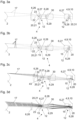
- a holding device 31 for a head 32 with a chin rest 33 and a forehead support 45 arranged on the holding device 31.
- the holding device 31 and the chin rest 33 as well as the forehead support 45 align the head 32 with respect to the ophthalmoscope 1 in such a way that the eye 2 is positioned in a fixed position for at least one image 16 through the ophthalmoscope 1.
- the holding device 31 is spaced from the at least one conversion device 4 by between 30 mm and 200 mm, wherein the spacing can be adjusted by an operator of the ophthalmoscope 1.
- the ophthalmoscope 1 is used on the human eye 2.
- Fig. 1b shows the ophthalmoscope 1 after Fig. 1a rotated 90 degrees in one direction around a vertical axis.
- Fig. 1c shows the ophthalmoscope 1 after Fig. 1a around a vertical axis by 90 degrees in the opposite direction.
- Fig. 2a shows the ophthalmoscope 1 according to Fig. 1a with a slit lamp 36.
- An image 16 on the at least one conversion device 4 can be displayed in color.
- a sensor-side numerical aperture of the objective 5 is in the range from 0.04 to 0.1.
- the objective 5 has an aperture, wherein the aperture has a radius in the range from 2.5 mm to 3.5 mm during imaging of the eye 2 by the ophthalmoscope 1 (not shown for reasons of clarity).
- the objective lens may also have an object-side numerical aperture, preferably in the range of 0.04 to 0.1.
- Fig. 2b shows the ophthalmoscope 1 after Fig. 2a rotated 180 degrees around a vertical axis.
- Fig. 2c shows that Ophthalmoscope 1 after Fig. 2a in a perspective view from the front.
- the eye 2 has a contact lens and a tear fluid enriched with fluorescent dye as the fluorescent dye, wherein the tear fluid is illuminated with a fluorescent light 35, the tear fluid can emit light in a wavelength range between 515 nm and 530 nm and a distribution of the emitted light of the tear fluid between the contact lens and the eye 2 is recorded on the at least one conversion device 4.
- the fluorescent dye is indocyanine green, the emitted light has a wavelength in the range from 825 nm to 835 nm.
- a blood vessel structure 46 and/or a lymph vessel structure and/or a corneal epithelium of the eye 2 can be imaged on the at least one conversion device 4.
- a fluorescence filter 43 is particularly preferably used here (not shown for reasons of clarity).
- the image 16 can then be stored on a computer 34.
- the ophthalmoscope 1 comprises a status screen 44, wherein electronic information is visualized on the status screen 44.
- Figures 16 can be repeated at any desired interval.
- Fig. 3a shows a sectional view of a surface geometry of an eye 2, a lens 5 and a device for conversion 4.
- the device for conversion 4 is designed in the form of a planar chip 9, wherein the chip 9 is designed as a CMOS sensor 10.
- the CMOS sensor 10 comprises a Bayer filter 11 (not shown for reasons of clarity).
- the objective lens 5 comprises eight lenses 6 and two faceplates 20.
- the lenses 6 are spherical, but can generally also be aspherical.
- a beam path 17 of light hits the CMOS sensor 10 after transmission through the lens 5, wherein the light of the eye 2 is transmitted in chronological order through an objective lens 26, a red dot reticle 21, a meniscus lens 27, an object-side air lens 6, an object-side diverging lens 28, an aperture, a converging lens 29, an achromat 30, a sensor-side meniscus lens 27, a sensor-side diverging lens 28 and a protective glass.
- Two such beam paths 17 are shown in the illustration, whereby - starting from the eye 2 - the upper beam path 17 starts from a more strongly curved area of the surface geometry of the eye 2 and the lower beam path 17 starts from a less curved area of the surface geometry of the eye 2. Due to the transmission through the eight lenses 6, the upper Beam path at a lower region and the lower beam path at an upper region relative to the lower region of the CMOS sensor 10.
- One faceplate 20 comprises the illuminated dot reticle 21 and the second faceplate 20 acts as a protective glass for the conversion device 4.
- Four lenses 6 are designed in the form of two air lenses 12 spaced apart from one another, wherein a Petzval sum of the two air lenses 12 is negative.
- the two air lenses are biconvex.
- the two air lenses 12 each comprise a lens-shaped fluid inclusion 15, wherein the lens-shaped fluid inclusion 15 is arranged between a sensor-side lens 6 and an object-side lens 6.
- the Petzval sum of the sensor-side lens 6, the object-side lens 6 and the fluid inclusion 15 is negative.
- the air lens 12 is designed such that a lens 6 with a first refractive index is arranged on the object side and a lens 6 with a second refractive index is arranged on the sensor side, wherein the second refractive index is higher than the first refractive index.
- Fig. 3b shows the eye 2, the lens 5 and the conversion device 4 according to the Fig. 3a shown embodiment, wherein two further beam paths 17 are shown for the upper and lower beam paths 17, each of which has a smaller or larger opening angle to a longitudinal alignment of the
- the reason for the sharp image 16 of the eye 2 on the CMOS sensor 10 is a convexly curved focus surface 7 (not shown for reasons of clarity) of the lens 5.
- a sharp image 16 of the eye 2 on the CMOS sensor 10 is the result of this structural design of the lens 5.
- Fig. 3c shows the lens 5 according to Fig. 3a , whereby different beam paths 17, starting from a point on the surface of the eye 2, are each imaged by the lens 5 onto the same point on the CMOS sensor 10. A blurred image 16 is thereby prevented.
- the objective lens 26, the object-side meniscus lens 27 and the achromat 30 comprise flint glass.
- the converging lens 29 and the achromat 30 comprise crown glass.
- the lens 5 can also comprise one or more mirrors 42 (not visible in the illustration) in order to direct the beam paths 17 in a particularly favorable manner onto the CMOS sensor 10 and to improve a sharp image 16 of the eye 2.
- a fluorescence filter 43 is arranged between the at least one conversion device 4 and the eye 2.
- the fluorescence filter is particularly preferably placed in the focus of one of the lenses 6.
- a pupil diaphragm can be arranged between the diverging lens 28 and the converging lens 29.
- Fig. 3d shows the lens 5 according to Fig. 3a , wherein it can be seen that the lens 5 and an object-side image 16a (not shown for reasons of clarity) and an object-side beam path 17 are essentially telecentric.
- the lens 5, the object-side image 16 and the object-side beam path 17 can also be pericentric.
- the illuminated dot reticle 21 is arranged in the at least one lens 5, centrally located on an optical axis 22 of the at least one lens 5. This also enables a standardization of the images 16 of the eye 2, since the Alignment of the eye 2 can be re-directed to the desired position after an interruption of recordings by the ophthalmoscope 1.
- the illuminated dot reticle 21 comprises a diffractive structure 23, wherein the diffractive structure 23 has an extension in the range of 25 ⁇ m to 75 ⁇ m.
- the illuminated dot reticle 21 is covered on the sensor side by a mask 24 (not shown for reasons of clarity) in order not to impair the image 16 of the eye 2 on the conversion device 4.
- the diffractive structure 23 can be illuminated laterally with an LED in any color, wherein the light of the LED is redirected in the direction of the eye.
- An optical length of the beam paths is the same. To achieve this, an optical density is increased at the edge and reduced in the center. This compensation can be generated by biconvex air lenses 12.
- the lens 5 is designed in such a way that optical transmission is homogeneous and particularly high across the entire field.
- Fig.4 shows an objective lens 5, wherein the housing 3 comprises an edge cylinder 25.
- the edge cylinder 25 is blackened. It can also be provided that the edge cylinder 25 is blackened only in an area of the illuminated dot reticle 21.
- a lighting 35 is arranged on the housing 3, wherein the illumination of the eye 2 via the lighting 35 is partially covered by the lens 5.
- the shape of the illumination 35 is generally arbitrary. Particularly preferred is an illumination 35 which is arranged in a ring shape around the housing 3. However, several illuminations 35 can also be arranged on the housing 3 or an illumination 35 in the form of a commercially available lamp can be used.
- the illumination of the eye 2 which is covered by the lens 5 would lead to undesirable reflections on the conversion device 4, which would also lead to undesirable overexposure of areas of the eye 2.
- the covered area of the illumination can reduce dilation of the pupil and/or the sensation of pain. Central areas of a cornea are therefore not directly illuminated, but this area of the illumination is deflected or shaded.
- the illumination 35 is designed such that the light of the illumination 35, which is diffusely scattered when penetrating the cornea and a sclera, contributes to the image 16.
- the light of the illumination 35 increases in the direction of an outer region of the eye 2 in order to generate a homogeneous brightness distribution on the conversion device 4.
- the illumination 35 can be in the form of white light illumination, for example with a sunlight-like white tone with a characteristic color temperature between 5000 K and 6000 K and/or a color rendering index of at least 95 % are present.
- the illumination 35 can comprise polychromatic light.
- the illumination 35 can also be designed as fluorescent illumination, for example with a wavelength range between 450 nm and 510 nm and/or between 750 nm and 780 nm.
- Fig.5 shows an ophthalmoscope 1, wherein the device for converting 4 of the ophthalmoscope 1 is in direct data connection with a computer 34.
- the computer 34 is in signal-transmitting data connection with a database on a decentralized computer.
- the database can also be present directly on the computer 34.
- the computer program product can also select a color of a contact lens and an artificial iris depending on a color of two irises, wherein the color of the contact lens and the artificial iris is adapted to one of the two irises.
- the computer program product can automatically recognize the blood vessel structure 46 and, for example, use artificial intelligence to do so.
- a quantification of changes in the blood vessel structure 46 and/or the corneal structure can also be calculated via the image overlay.
- red pixel density measurement integrates an entire red component of the at least one image 16 and/or calculates an area proportion of the blood vessel structure 46 on the at least one image 16.
- the computer program product comprises an automatic lesion detection of the eye 2 and can detect an opening of the eye 2 of at least 12 mm, wherein in the case of a opening of less than 12 mm, electronic information is transmitted to at least one status screen 44 of the ophthalmoscope 1.
- the ophthalmoscope 1 can be used in a stand-alone version or as an add-on version for a commercially available slit lamp 36.
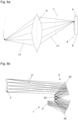
- Fig. 6a shows a concavely curved object with a concavely curved object surface and a device for conversion 4.
- Beam paths 17 visualize the transmission of light through a lens 6, starting from the concavely curved object in the direction of the device for conversion 4.
- the concavely curved object surface would be imaged onto a concavely curved image surface 8 (indicated by a dashed line).
- the lens 6 enables an image 16 onto a planar device for conversion 4, whereby the image surface 8 is also planar (indicated by a dashed line).
- the concavely curved image surface 8 can thus be sharply imaged onto the device for conversion 4 by the lens 6.
- the convexity of this lens 6 would be further increased, whereby a sharp image 16 onto the planar device for conversion 4 would not be possible.
- the focus area 7 is defined to the right of the lens 6, whereby in the illustration the focus area 7 is indicated by a dashed line in the image plane.
- the focus area 7 is concave, whereby According to the invention, a convex sharpening surface 7 is provided.
- Fig. 6b shows beam paths 17 between an eye 2 and a conversion device 4, wherein the beam paths 17 are deflected by three mirrors 42 onto the conversion device.
- the mirrors 42 are designed as free-form mirrors. However, the mirrors 42 can also comprise other types of mirrors.
- the objective lens 5 of the ophthalmoscope has a curved focus surface 7 (not shown for reasons of clarity) in order to be able to image the eye 2 sharply onto the conversion device 4.
- the lens 5 on the eye 2 in combination with at least one lens 6.
- Fig. 7a shows an illustration 16 of a human eye 2.
- a blood vessel structure 46 can be seen, wherein the blood vessel structure 46 can be identified by a reddish color.
- Fig. 7b shows a blood vessel structure 46, which extends over the image 16 of the eye 2 to Fig. 7a generated by the computer program product with automatic blood vessel detection.
- an analysis, a categorization and/or a red pixel density measurement of the image 16 of the eye can be carried out.
Landscapes
- Health & Medical Sciences (AREA)
- Life Sciences & Earth Sciences (AREA)
- Physics & Mathematics (AREA)
- Engineering & Computer Science (AREA)
- Surgery (AREA)
- General Health & Medical Sciences (AREA)
- Veterinary Medicine (AREA)
- Medical Informatics (AREA)
- Molecular Biology (AREA)
- Biomedical Technology (AREA)
- Animal Behavior & Ethology (AREA)
- Public Health (AREA)
- Biophysics (AREA)
- Heart & Thoracic Surgery (AREA)
- Ophthalmology & Optometry (AREA)
- Nuclear Medicine, Radiotherapy & Molecular Imaging (AREA)
- Radiology & Medical Imaging (AREA)
- Optics & Photonics (AREA)
- General Physics & Mathematics (AREA)
- Hematology (AREA)
- Vascular Medicine (AREA)
- Pathology (AREA)
- Human Computer Interaction (AREA)
- Analytical Chemistry (AREA)
- Biochemistry (AREA)
- Chemical & Material Sciences (AREA)
- Immunology (AREA)
- Eye Examination Apparatus (AREA)
- Stereoscopic And Panoramic Photography (AREA)
- Lenses (AREA)
Claims (15)
- Ophtalmoscope (1) pour l'examen d'une surface visible des yeux (2) comprenant- un boîtier (3),- au moins un dispositif de conversion (4) de lumière en un signal électrique sous la forme d'une puce planaire (9) et- au moins un objectif (5), dans lequel l'au moins un objectif (5) comprend au moins une lentille (6) et/ou au moins un miroir (42),caractérisé en ce que l'au moins objectif (5) présente une surface de mise au point (7) incurvée de manière convexe comme la surface qui est générée lors d'une projection d'un plan d'objet par l'objectif (5) afin de représenter de manière modifiée une surface d'image d'une surface d'objet sur le dispositif de conversion, dans lequel une surface d'image (8) incurvée de manière convexe d'un œil (2) peut être imagée par l'au moins un objectif (5) de manière nette sur l'au moins un dispositif de conversion (4), dans lequel la zone visible entière de l'œil (2) peut être imagée de manière nette sur l'au moins un dispositif de conversion (4) et dans lequel l'ophtalmoscope (1) comprend un éclairage (35) pulsé.
- Ophtalmoscope (1) selon la revendication 1, dans lequel- l'éclairage (35) est réalisé de telle manière que la lumière de l'éclairage (35) qui est dispersée de manière diffuse lors d'une pénétration dans la cornée et une sclère, contribue à la reproduction (16), et/ou- une résolution de l'image de l'œil (2) est telle qu'il existe un contraste d'une paire de lignes entre des pixels contigus séparés sur l'au moins un dispositif de conversion (4) d'au moins 20 %, de préférence d'au moins 30 %, et/ou- l'au moins un éclairage (35) est ou peut être commandé avec un signal de modulation d'impulsions en largeur.
- Ophtalmoscope (1) selon la revendication 1 ou 2, dans lequel l'au moins un dispositif de conversion (4)- est réalisé comme CMOS (10) et/ou- comprend au moins un filtre Bayer (11).
- Ophtalmoscope (1) selon l'une quelconque des revendications précédentes, dans lequel un ensemble de lentille est prévu avec la somme de Petzval négative pour la reproduction de la surface d'image (8) incurvée de manière convexe de l'œil (2) et/ou au moins deux lentilles (6) sont réalisées sous la forme d'au moins une lentille d'air (12), dans lequel une somme de Petzval de l'au moins une lentille d'air (12) est négative, dans lequel un mélange de gaz avec un indice de réfaction inférieur à 1,3, de préférence inférieur à 1,1 est de préférence agencé à l'intérieur de l'au moins une lentille d'air (12), dans lequel il est de préférence prévu que le mélange de gaz contienne au moins un gaz rare, de manière particulièrement préférée de l'argon, de l'azote et/ou de l'air, se présente de manière particulièrement préférée sous la forme de gaz rare, d'azote ou d'air.
- Ophtalmoscope (1) selon l'une quelconque des revendications précédentes, dans lequel une inclusion de fluide (15) en forme de lentille est agencée entre une lentille (6) côté capteur et une lentille (6) côté objet, dans lequel la somme de Petzval de la lentille (6) côté capteur, de la lentille (6) côté objet et de l'inclusion de fluide (15) est négative.
- Ophtalmoscope (1) selon la revendication 4 ou 5, dans lequel- l'au moins une lentille d'air (12) est réalisée de telle manière qu'une lentille (6) avec un premier indice de réfraction soit agencée côté objet et une lentille (6) avec un deuxième indice de réfraction soit agencée côté capteur, dans lequel le deuxième indice de réfraction est supérieur au premier indice de réfraction et/ou l'au moins une lentille d'air (12) est réalisée de manière biconvexe, et/ou- précisément deux lentilles d'air (12) espacées l'une de l'autre sont présentes.
- Ophtalmoscope (1) selon l'une quelconque des revendications précédentes, dans lequel- l'au moins un objectif (5) et/ou une reproduction (16a) côté objet et/ou une trajectoire de faisceau (17) côté objet est réalisé(e) sensiblement de manière télécentrique, de préférence péricentrique,- une reproduction (16) est représentée en couleur sur l'au moins un dispositif de conversion (4),- une ouverture numérique côté capteur de l'au moins un objectif (5) se trouve dans la plage de 0,04 à 0,1, de préférence dans la plage de 0,06 à 0,08,- l'au moins un objectif (5) présente un diaphragme, dans lequel le diaphragme présente un rayon dans la plage de 2,5 mm à 3,5 mm, de préférence dans la plage de 2,9 à 3,3,- l'ophtalmoscope (1) comprend précisément huit lentilles (6) et/ou précisément deux plateaux circulaires (20),- au moins une lentille (6) est réalisée de manière asphérique,- au moins un réticule de point lumineux (21) est agencé dans l'au moins un objectif (5), de préférence localisé de manière centrale sur un axe optique (22) de l'au moins un objectif (5), dans lequel il est de préférence prévu que l'au moins un réticule de point lumineux (21) comprenne au moins une structure diffractive (23), dans lequel l'au moins une structure diffractive (23) présente une extension dans la plage de 25 µm à 75 µm, de préférence dans la plage de 40 µm à 55 µm et/ou l'au moins un réticule de point lumineux (21) est recouvert côté capteur par un masque (24), et/ou- le boîtier (3) comprend au moins un cylindre de bord (25), dans lequel l'au moins un cylindre de bord (25) est réalisé de manière noircie de préférence dans la zone de l'au moins un réticule de point lumineux (21).
- Ophtalmoscope (1) selon la revendication 7, dans lequel la lumière de l'œil (2) peut être transmise dans l'ordre chronologique par une lentille d'objectif (26), le réticule de point lumineux (21), une lentille ménisque (27), une lentille d'air (14) côté objet, une lentille divergente (28) côté objet, l'obturateur, une lentille convergente (29), une lentille achromatique (30), une lentille ménisque (27) côté capteur, une lentille divergente (28) côté capteur et un verre de protection, dans lequel la lumière de l'œil (2) peut être rencontrée ensuite sur l'au moins un dispositif de conversion (4), dans lequel il est de préférence prévu que la lentille d'objectif (26) et/ou la lentille ménisque (27) côté objet et/ou la lentille achromatique (30) comprenne du verre flint et/ou la lentille convergente (29) et/ou la lentille achromatique (30) comprenne du verre crown.
- Ophtalmoscope (1) selon l'une quelconque des revendications précédentes, dans lequel- au moins un dispositif de retenue (31) est prévu pour une tête (32), de préférence avec un support de menton (33) et/ou un support frontal (45), dans lequel il est de préférence prévu que le dispositif de retenue (31) soit espacé de l'au moins un dispositif de conversion (4) dans la plage de 30 mm à 200 mm, de préférence dans la plage de 40 mm à 100 mm,- l'au moins un dispositif de conversion (4) peut être amené en liaison de données avec au moins un ordinateur (34), dans lequel l'au moins un ordinateur (34) peut être amené en liaison avec une base de données,- au moins un éclairage (35) est agencé sur le boîtier (3), dans lequel l'illumination de l'œil (2) est recouverte par le biais de l'au moins un éclairage (35) par endroits par l'au moins un objectif (5), dans lequel il est de préférence prévu que l'au moins un éclairage (35) soit configuré sous la forme d'un éclairage de lumière blanche, de préférence avec une nuance de blanc similaire à la lumière du soleil avec une température de couleur caractéristique entre 5000 K et 6000 K et/ou un indice de rendu de couleur d'au moins 95 %, et/ou un éclairage fluorescent et/ou l'éclairage fluorescent présente une plage de longueur d'onde entre 450 nm et 510 nm et/ou entre 750 nm et 780 nm,- au moins un filtre de fluorescence (43) est agencé entre l'au moins un dispositif de conversion (4) et l'œil (2), et/ou- l'ophtalmoscope (1) comprend au moins un écran de statut (44), dans lequel au moins une information électronique est visualisable sur l'au moins un écran de statut (44).
- Ophtalmoscope (1) selon l'une quelconque des revendications 1 à 9 avec une lampe à fente (36).
- Utilisation d'un ophtalmoscope (1) selon l'une quelconque des revendications 1 à 10 sur l'œil humain (2).
- Procédé d'examen d'yeux (2) comprenant les étapes suivantes- l'ajustement grossier d'un patient dans un dispositif de retenue (31), en particulier avec une précision inférieure à 3 mm,- la reconnaissance d'une pupille et/ou d'un sommet d'une cornée de l'œil (2) par le biais d'un programme de traitement d'image, dans lequel il est en particulier prévu que le programme de traitement d'image présente un algorithme de mise au point automatique,- la prise d'au moins une reproduction (16) de l'œil (2) par un ophtalmoscope (1) selon l'une quelconque des revendications 1 à 10, dans lequel l'au moins une reproduction (16) de l'œil (2) est prise sur au moins un dispositif de conversion (4).
- Procédé selon la revendication 12, dans lequel- des déplacements de l'œil (2) inférieurs à 3 mm sont suivis par une poursuite automatisée et/ou une ouverture d'une paupière est reconnue par le biais du programme de traitement d'image, dans lequel il est de préférence prévu que lors d'une ouverture inférieure à 12 mm, de préférence inférieure à 16 mm, une indication soit affichée sur au moins un écran de statut (44),- l'au moins une reproduction (16) de l'œil (2) est lue et/ou enregistrée sur l'au moins un dispositif de conversion (4) dans au moins un ordinateur (34), de préférence dans une base de données sur l'au moins un ordinateur (34),- l'au moins une reproduction (16) de l'œil (2) est évaluée et/ou analysée en ce qui concerne des caractéristiques spécifiques aux yeux,- l'au moins une reproduction (16) de l'œil (2) est catégorisée sur au moins un ordinateur (34) de standardisation et/ou de normalisation,- l'œil (2) présente une lentille de contact et un liquide lacrymal enrichi avec un colorant fluorescent, dans lequel le liquide lacrymal est irradié avec un éclairage (35) fluorescent, le liquide lacrymal émet de la lumière dans une plage de longueur d'onde entre 515 m et 530 nm et/ou entre 825 nm et 835 nm et une distribution de la lumière émise du liquide lacrymal est prise entre la lentille de contact et l'œil (2) sur l'au moins un dispositif de conversion (4), et/ou- l'œil (2) comprend au moins un colorant fluorescent et une structure de vaisseau sanguin (46) et/ou une structure de vaisseau lymphatique et/ou un épithélium cornéen de l'œil (2) est imagé(e), de préférence par le biais de l'au moins un filtre de fluorescence (43), sur l'au moins un dispositif de conversion (4), et/ou est enregistré(e) sur l'au moins un ordinateur (34), dans lequel il est de préférence prévu que le colorant fluorescent comprenne de la fluorescence et/ou du vert d'indocyanine.
- Ophtalmoscope selon l'une quelconque des revendications 1 à 10, avec un produit de programme informatique, comprenant des ordres, qui, lors de la réalisation par une unité de calcul (40), amènent celle-ci à classifier, pour l'ophtalmoscope (1) selon l'une quelconque des revendications 1 à 10 pour l'examen d'yeux (2) à partir d'une unité de mémoire (41) qui est dans une liaison de données avec l'unité de calcul (40) ou peut être amenée dans une telle liaison, au moins une reproduction (16) d'un œil (2), dans lequel une classification est générée sur la base d'une structure de vaisseau sanguin (46) et/ou d'une structure de cornée et/ou d'une structure de cicatrice et/ou d'une structure d'orbite.
- Ophtalmoscope (1) selon la revendication 14, dans lequel, par le produit de programme informatique- une superposition d'image avec une reconnaissance de vaisseau sanguin automatique et/ou reconnaissance de limbe peut être utilisée pour le contrôle de la classification,- une reconnaissance de lésion semi-automatique et/ou des mesures bidirectionnelles peuvent être entreprises,- des reproductions (16) standardisées au moins d'un iris sont enregistrées dans l'unité de mémoire (41), dans lequel il est de préférence prévu qu'en fonction d'une couleur de deux iris, une couleur d'une lentille de contact et/ou d'un iris artificiel soit sélectionnée, dans lequel la couleur de la lentille de contact et/ou l'iris artificiel est adaptée à l'un des deux iris,- la structure de vaisseau sanguin (46) est automatiquement reconnue de préférence par le biais d'une intelligence artificielle,- une quantification de modifications de la structure de vaisseau sanguin (46) et/ou de la structure de cornée est calculée par le biais de la superposition d'image,- une densimétrie de pixel rouge est entreprise, dans lequel la mesure de pixel rouge intègre une part rouge entière de l'au moins une reproduction (16) et/ou calcule une part de surface de la structure de vaisseau sanguin (46) au niveau de l'au moins une reproduction (16), et/ou- une ouverture de l'œil (2) d'au moins 12 mm, de préférence d'au moins 16 mm est reconnue et lors d'une ouverture inférieure à 12 mm, de préférence inférieure à 16 mm, une information électronique est transmise à l'au moins un écran de statut (44), et/ou le produit de programme informatique comprend une reconnaissance de lésion automatique de l'œil (2).
Applications Claiming Priority (2)
| Application Number | Priority Date | Filing Date | Title |
|---|---|---|---|
| ATA60282/2019A AT523322A3 (de) | 2019-12-19 | 2019-12-19 | Ophthalmoskop zur Untersuchung von Augen |
| PCT/AT2020/060415 WO2021119684A1 (fr) | 2019-12-19 | 2020-11-23 | Ophtalmoscope destinée à l'examen des yeux |
Publications (3)
| Publication Number | Publication Date |
|---|---|
| EP4076140A1 EP4076140A1 (fr) | 2022-10-26 |
| EP4076140B1 true EP4076140B1 (fr) | 2024-08-21 |
| EP4076140C0 EP4076140C0 (fr) | 2024-08-21 |
Family
ID=73694689
Family Applications (1)
| Application Number | Title | Priority Date | Filing Date |
|---|---|---|---|
| EP20817207.2A Active EP4076140B1 (fr) | 2019-12-19 | 2020-11-23 | Ophtalmoscope destinée à l'examen des yeux |
Country Status (6)
| Country | Link |
|---|---|
| US (1) | US20220313086A1 (fr) |
| EP (1) | EP4076140B1 (fr) |
| CN (1) | CN115135227A (fr) |
| AT (1) | AT523322A3 (fr) |
| AU (1) | AU2020406662B2 (fr) |
| WO (1) | WO2021119684A1 (fr) |
Families Citing this family (2)
| Publication number | Priority date | Publication date | Assignee | Title |
|---|---|---|---|---|
| WO2025072822A1 (fr) * | 2023-09-28 | 2025-04-03 | Ora Llc | Systèmes et procédés d'évaluation d'affections oculaires |
| WO2025193780A1 (fr) * | 2024-03-12 | 2025-09-18 | Oculogica, Inc. | Dispositif de détection d'utilisation de substance |
Citations (1)
| Publication number | Priority date | Publication date | Assignee | Title |
|---|---|---|---|---|
| US7621638B2 (en) * | 2006-11-29 | 2009-11-24 | Clarity Medical Systems, Inc. | Delivering a short Arc lamp light for eye imaging |
Family Cites Families (14)
| Publication number | Priority date | Publication date | Assignee | Title |
|---|---|---|---|---|
| JPH0824223A (ja) * | 1994-07-15 | 1996-01-30 | Canon Inc | 眼科撮影装置 |
| US6577387B2 (en) * | 2000-12-29 | 2003-06-10 | Johnson & Johnson Vision Care, Inc. | Inspection of ophthalmic lenses using absorption |
| US6741359B2 (en) * | 2002-05-22 | 2004-05-25 | Carl Zeiss Meditec, Inc. | Optical coherence tomography optical scanner |
| DE10250569A1 (de) * | 2002-10-28 | 2004-05-13 | Carl Zeiss Meditec Ag | Ophthalmologisches Gerät und Verfahren zur Gerätepositionierung |
| EP2231277B1 (fr) * | 2007-12-23 | 2017-08-30 | Carl Zeiss Meditec, Inc. | Dispositifs permettant de détecter, contrôler et prévoir l'administration d'un rayonnement |
| GB2467788B (en) * | 2009-02-16 | 2014-05-07 | Qioptiq Ltd | An optical adaptor |
| WO2010099289A1 (fr) * | 2009-02-25 | 2010-09-02 | University Of Iowa Research Foundation | Ophtalmoscope laser hybride |
| RU2440802C2 (ru) * | 2010-03-30 | 2012-01-27 | Игорь Михайлович Корниловский | Способ оценки переносимости роговицей контактной линзы и выбора режима ее ношения |
| WO2014022965A1 (fr) * | 2012-08-07 | 2014-02-13 | 展讯通信(上海)有限公司 | Procédé et dispositif de traitement d'image basés sur un format bayer |
| CN105578947B (zh) * | 2013-07-02 | 2018-10-26 | 麻省理工学院 | 确定眼处方的装置和方法 |
| EP3424406A1 (fr) * | 2016-11-22 | 2019-01-09 | Delphinium Clinic Ltd. | Procédé et système de classification de tête de nerf optique |
| DE102016226002A1 (de) * | 2016-12-22 | 2018-06-28 | Carl Zeiss Meditec Ag | Anordnung zur Anpassung der Fokalebene eines optischen Systems an ein nicht-planes, insbesondere sphärisches Objekt |
| WO2019189222A1 (fr) * | 2018-03-30 | 2019-10-03 | 株式会社ニコン | Système optique ophtalmique, lentille d'objet pour ophtalmologie, et dispositif ophtalmique |
| DE102018218107A1 (de) * | 2018-10-23 | 2018-12-20 | Carl Zeiss Smt Gmbh | Optische Anordnung zur Bauteilinspektion von Bauteilen mit einer gekrümmten Oberfläche und Inspektionsverfahren hierzu |
-
2019
- 2019-12-19 AT ATA60282/2019A patent/AT523322A3/de unknown
-
2020
- 2020-11-23 AU AU2020406662A patent/AU2020406662B2/en active Active
- 2020-11-23 WO PCT/AT2020/060415 patent/WO2021119684A1/fr not_active Ceased
- 2020-11-23 CN CN202080096810.5A patent/CN115135227A/zh active Pending
- 2020-11-23 EP EP20817207.2A patent/EP4076140B1/fr active Active
-
2022
- 2022-06-17 US US17/843,020 patent/US20220313086A1/en not_active Abandoned
Patent Citations (1)
| Publication number | Priority date | Publication date | Assignee | Title |
|---|---|---|---|---|
| US7621638B2 (en) * | 2006-11-29 | 2009-11-24 | Clarity Medical Systems, Inc. | Delivering a short Arc lamp light for eye imaging |
Also Published As
| Publication number | Publication date |
|---|---|
| AU2020406662A1 (en) | 2022-07-28 |
| EP4076140A1 (fr) | 2022-10-26 |
| CN115135227A (zh) | 2022-09-30 |
| AU2020406662B2 (en) | 2023-09-28 |
| WO2021119684A1 (fr) | 2021-06-24 |
| US20220313086A1 (en) | 2022-10-06 |
| AT523322A2 (de) | 2021-07-15 |
| AT523322A3 (de) | 2024-08-15 |
| EP4076140C0 (fr) | 2024-08-21 |
Similar Documents
| Publication | Publication Date | Title |
|---|---|---|
| DE112013006234B4 (de) | Ophthalmologische Vorrichtung | |
| EP2564763B1 (fr) | Appareil d'analyse ophtalmologique et procédé | |
| DE102015203443B4 (de) | Ophthalmologische Bildgebungsvorrichtung und optische Einheit, die an dieser befestigbar ist | |
| DE60038008T2 (de) | Vorrichtung zur bilderzeugung von augengewebe | |
| DE69032910T2 (de) | Kontaktlinsensystem zur indirekten diagnostischen ophthalmoskopie | |
| DE60206510T2 (de) | System zur berechnung des durchmessers der vorderkammer aus messungen des limbusringes | |
| EP2104448A2 (fr) | Système optique pour caméra d'observation | |
| DE3122029A1 (de) | Verfahren und vorrichtung zur hornhaut-formanalyse | |
| EP1731086A2 (fr) | Méthode d'opération d'un système d'analyse ophtalmologigique | |
| DE19609101A1 (de) | Augenvermessungsvorrichtung und -verfahren | |
| WO1988003396A1 (fr) | Dispositif pour la production d'images d'un objet et notamment pour l'observation des parties arriere de l'oeil | |
| EP2446813B1 (fr) | Appareil ophthalmique pour l'analyse | |
| EP1692998B1 (fr) | Système d'analyse ophthalmologique permettant la mesure de la pression intraoculaire | |
| DE112016004722T5 (de) | Ophthalmobildgebungsvorrichtung und Ophthalmoinformationsverarbeitungsvorrichtung | |
| WO2002094088A2 (fr) | Ophtalmoscope | |
| EP2148610A1 (fr) | Procédé et système de mesure oculaire | |
| EP4076140A1 (fr) | Ophtalmoscope destinée à l'examen des yeux | |
| DE69023007T2 (de) | Keratoskop mit auswechselbaren konen. | |
| WO2009143976A1 (fr) | Système optique pour appareils ophtalmologiques, notamment caméras d’ophtalmoscopie | |
| DE10326527A1 (de) | Verfahren und Vorrichtung zur Bestimmung einer Bewegung eines menschlichen Auges | |
| DE4422071B4 (de) | Netzhaut-Blutströmungsgeschwindigkeits-Meßeinrichtung | |
| DE10138158A1 (de) | Verfaren und Vorrichtung zur kontaktlosen Gewinnung von Bildern der Kornea | |
| WO2018114636A1 (fr) | Dispositif d'adaptation du plan focal d'un système optique à un objet non plan, en particulier un objet sphérique | |
| DE102012019468A1 (de) | Vorrichtung und Verfahren zur registrierten Bestimmung der Krümmung der Hornhaut eines Auges | |
| DE112007000242T5 (de) | Verbesserte diagnostische ophthalmologische Linse aus einem Material mit besonders niedriger Dispersion |
Legal Events
| Date | Code | Title | Description |
|---|---|---|---|
| STAA | Information on the status of an ep patent application or granted ep patent |
Free format text: STATUS: UNKNOWN |
|
| STAA | Information on the status of an ep patent application or granted ep patent |
Free format text: STATUS: THE INTERNATIONAL PUBLICATION HAS BEEN MADE |
|
| PUAI | Public reference made under article 153(3) epc to a published international application that has entered the european phase |
Free format text: ORIGINAL CODE: 0009012 |
|
| STAA | Information on the status of an ep patent application or granted ep patent |
Free format text: STATUS: REQUEST FOR EXAMINATION WAS MADE |
|
| 17P | Request for examination filed |
Effective date: 20220525 |
|
| AK | Designated contracting states |
Kind code of ref document: A1 Designated state(s): AL AT BE BG CH CY CZ DE DK EE ES FI FR GB GR HR HU IE IS IT LI LT LU LV MC MK MT NL NO PL PT RO RS SE SI SK SM TR |
|
| DAV | Request for validation of the european patent (deleted) | ||
| DAX | Request for extension of the european patent (deleted) | ||
| STAA | Information on the status of an ep patent application or granted ep patent |
Free format text: STATUS: EXAMINATION IS IN PROGRESS |
|
| 17Q | First examination report despatched |
Effective date: 20230725 |
|
| REG | Reference to a national code |
Ref country code: DE Ref legal event code: R079 Free format text: PREVIOUS MAIN CLASS: A61B0003100000 Ipc: A61B0001010000 Ref document number: 502020008973 Country of ref document: DE |
|
| GRAP | Despatch of communication of intention to grant a patent |
Free format text: ORIGINAL CODE: EPIDOSNIGR1 |
|
| STAA | Information on the status of an ep patent application or granted ep patent |
Free format text: STATUS: GRANT OF PATENT IS INTENDED |
|
| RIC1 | Information provided on ipc code assigned before grant |
Ipc: A61B 1/01 20060101AFI20240325BHEP |
|
| INTG | Intention to grant announced |
Effective date: 20240416 |
|
| GRAS | Grant fee paid |
Free format text: ORIGINAL CODE: EPIDOSNIGR3 |
|
| GRAA | (expected) grant |
Free format text: ORIGINAL CODE: 0009210 |
|
| STAA | Information on the status of an ep patent application or granted ep patent |
Free format text: STATUS: THE PATENT HAS BEEN GRANTED |
|
| AK | Designated contracting states |
Kind code of ref document: B1 Designated state(s): AL AT BE BG CH CY CZ DE DK EE ES FI FR GB GR HR HU IE IS IT LI LT LU LV MC MK MT NL NO PL PT RO RS SE SI SK SM TR |
|
| REG | Reference to a national code |
Ref country code: GB Ref legal event code: FG4D Free format text: NOT ENGLISH |
|
| REG | Reference to a national code |
Ref country code: CH Ref legal event code: EP |
|
| REG | Reference to a national code |
Ref country code: DE Ref legal event code: R096 Ref document number: 502020008973 Country of ref document: DE |
|
| REG | Reference to a national code |
Ref country code: IE Ref legal event code: FG4D Free format text: LANGUAGE OF EP DOCUMENT: GERMAN |
|
| U01 | Request for unitary effect filed |
Effective date: 20240917 |
|
| U07 | Unitary effect registered |
Designated state(s): AT BE BG DE DK EE FI FR IT LT LU LV MT NL PT RO SE SI Effective date: 20241008 |
|
| U20 | Renewal fee for the european patent with unitary effect paid |
Year of fee payment: 5 Effective date: 20241120 |
|
| PG25 | Lapsed in a contracting state [announced via postgrant information from national office to epo] |
Ref country code: NO Free format text: LAPSE BECAUSE OF FAILURE TO SUBMIT A TRANSLATION OF THE DESCRIPTION OR TO PAY THE FEE WITHIN THE PRESCRIBED TIME-LIMIT Effective date: 20241121 |
|
| PG25 | Lapsed in a contracting state [announced via postgrant information from national office to epo] |
Ref country code: PL Free format text: LAPSE BECAUSE OF FAILURE TO SUBMIT A TRANSLATION OF THE DESCRIPTION OR TO PAY THE FEE WITHIN THE PRESCRIBED TIME-LIMIT Effective date: 20240821 Ref country code: GR Free format text: LAPSE BECAUSE OF FAILURE TO SUBMIT A TRANSLATION OF THE DESCRIPTION OR TO PAY THE FEE WITHIN THE PRESCRIBED TIME-LIMIT Effective date: 20241122 |
|
| PG25 | Lapsed in a contracting state [announced via postgrant information from national office to epo] |
Ref country code: IS Free format text: LAPSE BECAUSE OF FAILURE TO SUBMIT A TRANSLATION OF THE DESCRIPTION OR TO PAY THE FEE WITHIN THE PRESCRIBED TIME-LIMIT Effective date: 20241221 |
|
| PG25 | Lapsed in a contracting state [announced via postgrant information from national office to epo] |
Ref country code: HR Free format text: LAPSE BECAUSE OF FAILURE TO SUBMIT A TRANSLATION OF THE DESCRIPTION OR TO PAY THE FEE WITHIN THE PRESCRIBED TIME-LIMIT Effective date: 20240821 |
|
| PG25 | Lapsed in a contracting state [announced via postgrant information from national office to epo] |
Ref country code: RS Free format text: LAPSE BECAUSE OF FAILURE TO SUBMIT A TRANSLATION OF THE DESCRIPTION OR TO PAY THE FEE WITHIN THE PRESCRIBED TIME-LIMIT Effective date: 20241121 Ref country code: ES Free format text: LAPSE BECAUSE OF FAILURE TO SUBMIT A TRANSLATION OF THE DESCRIPTION OR TO PAY THE FEE WITHIN THE PRESCRIBED TIME-LIMIT Effective date: 20240821 |
|
| PG25 | Lapsed in a contracting state [announced via postgrant information from national office to epo] |
Ref country code: RS Free format text: LAPSE BECAUSE OF FAILURE TO SUBMIT A TRANSLATION OF THE DESCRIPTION OR TO PAY THE FEE WITHIN THE PRESCRIBED TIME-LIMIT Effective date: 20241121 Ref country code: PL Free format text: LAPSE BECAUSE OF FAILURE TO SUBMIT A TRANSLATION OF THE DESCRIPTION OR TO PAY THE FEE WITHIN THE PRESCRIBED TIME-LIMIT Effective date: 20240821 Ref country code: NO Free format text: LAPSE BECAUSE OF FAILURE TO SUBMIT A TRANSLATION OF THE DESCRIPTION OR TO PAY THE FEE WITHIN THE PRESCRIBED TIME-LIMIT Effective date: 20241121 Ref country code: IS Free format text: LAPSE BECAUSE OF FAILURE TO SUBMIT A TRANSLATION OF THE DESCRIPTION OR TO PAY THE FEE WITHIN THE PRESCRIBED TIME-LIMIT Effective date: 20241221 Ref country code: HR Free format text: LAPSE BECAUSE OF FAILURE TO SUBMIT A TRANSLATION OF THE DESCRIPTION OR TO PAY THE FEE WITHIN THE PRESCRIBED TIME-LIMIT Effective date: 20240821 Ref country code: GR Free format text: LAPSE BECAUSE OF FAILURE TO SUBMIT A TRANSLATION OF THE DESCRIPTION OR TO PAY THE FEE WITHIN THE PRESCRIBED TIME-LIMIT Effective date: 20241122 Ref country code: ES Free format text: LAPSE BECAUSE OF FAILURE TO SUBMIT A TRANSLATION OF THE DESCRIPTION OR TO PAY THE FEE WITHIN THE PRESCRIBED TIME-LIMIT Effective date: 20240821 |
|
| PG25 | Lapsed in a contracting state [announced via postgrant information from national office to epo] |
Ref country code: SM Free format text: LAPSE BECAUSE OF FAILURE TO SUBMIT A TRANSLATION OF THE DESCRIPTION OR TO PAY THE FEE WITHIN THE PRESCRIBED TIME-LIMIT Effective date: 20240821 |
|
| PG25 | Lapsed in a contracting state [announced via postgrant information from national office to epo] |
Ref country code: CZ Free format text: LAPSE BECAUSE OF FAILURE TO SUBMIT A TRANSLATION OF THE DESCRIPTION OR TO PAY THE FEE WITHIN THE PRESCRIBED TIME-LIMIT Effective date: 20240821 |
|
| PG25 | Lapsed in a contracting state [announced via postgrant information from national office to epo] |
Ref country code: SK Free format text: LAPSE BECAUSE OF FAILURE TO SUBMIT A TRANSLATION OF THE DESCRIPTION OR TO PAY THE FEE WITHIN THE PRESCRIBED TIME-LIMIT Effective date: 20240821 |
|
| PLBE | No opposition filed within time limit |
Free format text: ORIGINAL CODE: 0009261 |
|
| STAA | Information on the status of an ep patent application or granted ep patent |
Free format text: STATUS: NO OPPOSITION FILED WITHIN TIME LIMIT |
|
| REG | Reference to a national code |
Ref country code: CH Ref legal event code: PL |
|
| PG25 | Lapsed in a contracting state [announced via postgrant information from national office to epo] |
Ref country code: MC Free format text: LAPSE BECAUSE OF FAILURE TO SUBMIT A TRANSLATION OF THE DESCRIPTION OR TO PAY THE FEE WITHIN THE PRESCRIBED TIME-LIMIT Effective date: 20240821 |
|
| REG | Reference to a national code |
Ref country code: CH Ref legal event code: PL |
|
| GBPC | Gb: european patent ceased through non-payment of renewal fee |
Effective date: 20241123 |
|
| PG25 | Lapsed in a contracting state [announced via postgrant information from national office to epo] |
Ref country code: CH Free format text: LAPSE BECAUSE OF NON-PAYMENT OF DUE FEES Effective date: 20241130 |
|
| 26N | No opposition filed |
Effective date: 20250522 |
|
| PG25 | Lapsed in a contracting state [announced via postgrant information from national office to epo] |
Ref country code: GB Free format text: LAPSE BECAUSE OF NON-PAYMENT OF DUE FEES Effective date: 20241123 |
|
| PG25 | Lapsed in a contracting state [announced via postgrant information from national office to epo] |
Ref country code: IE Free format text: LAPSE BECAUSE OF NON-PAYMENT OF DUE FEES Effective date: 20241123 |
|
| U20 | Renewal fee for the european patent with unitary effect paid |
Year of fee payment: 6 Effective date: 20251126 |
|
| PG25 | Lapsed in a contracting state [announced via postgrant information from national office to epo] |
Ref country code: HU Free format text: LAPSE BECAUSE OF FAILURE TO SUBMIT A TRANSLATION OF THE DESCRIPTION OR TO PAY THE FEE WITHIN THE PRESCRIBED TIME-LIMIT; INVALID AB INITIO Effective date: 20201123 |
|
| PG25 | Lapsed in a contracting state [announced via postgrant information from national office to epo] |
Ref country code: CY Free format text: LAPSE BECAUSE OF FAILURE TO SUBMIT A TRANSLATION OF THE DESCRIPTION OR TO PAY THE FEE WITHIN THE PRESCRIBED TIME-LIMIT; INVALID AB INITIO Effective date: 20201123 |