EP4077228B1 - Plaque d'extrémité et filière correspondante - Google Patents
Plaque d'extrémité et filière correspondante Download PDFInfo
- Publication number
- EP4077228B1 EP4077228B1 EP19829575.0A EP19829575A EP4077228B1 EP 4077228 B1 EP4077228 B1 EP 4077228B1 EP 19829575 A EP19829575 A EP 19829575A EP 4077228 B1 EP4077228 B1 EP 4077228B1
- Authority
- EP
- European Patent Office
- Prior art keywords
- tip plate
- section
- bushing
- sections
- tip
- Prior art date
- Legal status (The legal status is an assumption and is not a legal conclusion. Google has not performed a legal analysis and makes no representation as to the accuracy of the status listed.)
- Active
Links
Images


Classifications
-
- C—CHEMISTRY; METALLURGY
- C03—GLASS; MINERAL OR SLAG WOOL
- C03B—MANUFACTURE, SHAPING, OR SUPPLEMENTARY PROCESSES
- C03B37/00—Manufacture or treatment of flakes, fibres, or filaments from softened glass, minerals, or slags
- C03B37/08—Bushings, e.g. construction, bushing reinforcement means; Spinnerettes; Nozzles; Nozzle plates
- C03B37/0805—Manufacturing, repairing, or other treatment of bushings, nozzles or bushing nozzle plates
-
- C—CHEMISTRY; METALLURGY
- C03—GLASS; MINERAL OR SLAG WOOL
- C03B—MANUFACTURE, SHAPING, OR SUPPLEMENTARY PROCESSES
- C03B37/00—Manufacture or treatment of flakes, fibres, or filaments from softened glass, minerals, or slags
- C03B37/08—Bushings, e.g. construction, bushing reinforcement means; Spinnerettes; Nozzles; Nozzle plates
- C03B37/083—Nozzles; Bushing nozzle plates
-
- C—CHEMISTRY; METALLURGY
- C03—GLASS; MINERAL OR SLAG WOOL
- C03B—MANUFACTURE, SHAPING, OR SUPPLEMENTARY PROCESSES
- C03B37/00—Manufacture or treatment of flakes, fibres, or filaments from softened glass, minerals, or slags
- C03B37/08—Bushings, e.g. construction, bushing reinforcement means; Spinnerettes; Nozzles; Nozzle plates
- C03B37/09—Bushings, e.g. construction, bushing reinforcement means; Spinnerettes; Nozzles; Nozzle plates electrically heated
- C03B37/092—Direct-resistance heating
-
- C—CHEMISTRY; METALLURGY
- C03—GLASS; MINERAL OR SLAG WOOL
- C03B—MANUFACTURE, SHAPING, OR SUPPLEMENTARY PROCESSES
- C03B37/00—Manufacture or treatment of flakes, fibres, or filaments from softened glass, minerals, or slags
- C03B37/08—Bushings, e.g. construction, bushing reinforcement means; Spinnerettes; Nozzles; Nozzle plates
- C03B37/095—Use of materials therefor
-
- B—PERFORMING OPERATIONS; TRANSPORTING
- B33—ADDITIVE MANUFACTURING TECHNOLOGY
- B33Y—ADDITIVE MANUFACTURING, i.e. MANUFACTURING OF THREE-DIMENSIONAL [3D] OBJECTS BY ADDITIVE DEPOSITION, ADDITIVE AGGLOMERATION OR ADDITIVE LAYERING, e.g. BY 3D PRINTING, STEREOLITHOGRAPHY OR SELECTIVE LASER SINTERING
- B33Y80/00—Products made by additive manufacturing
-
- Y—GENERAL TAGGING OF NEW TECHNOLOGICAL DEVELOPMENTS; GENERAL TAGGING OF CROSS-SECTIONAL TECHNOLOGIES SPANNING OVER SEVERAL SECTIONS OF THE IPC; TECHNICAL SUBJECTS COVERED BY FORMER USPC CROSS-REFERENCE ART COLLECTIONS [XRACs] AND DIGESTS
- Y02—TECHNOLOGIES OR APPLICATIONS FOR MITIGATION OR ADAPTATION AGAINST CLIMATE CHANGE
- Y02P—CLIMATE CHANGE MITIGATION TECHNOLOGIES IN THE PRODUCTION OR PROCESSING OF GOODS
- Y02P10/00—Technologies related to metal processing
- Y02P10/25—Process efficiency
Definitions
- the invention relates to a tip plate for a bushing for receiving a high temperature melt and a corresponding bushing.
- the term "receiving" includes all kinds of preparing, storing and treating melts.
- the bushing and its tip plate are intended for use in the production of fibres, such as glass fibres, mineral fibres, basalt fibres etc.
- a generic bushing may be characterized as a box like melting vessel (crucible), often providing a cuboid space and comprising a bottom, the so called tip plate, as well as a circumferential wall.
- a generic tip plate comprises a body between an upper surface and a lower surface at a distance to the upper surface as well as a multiplicity of nozzles, extending between the upper surface and the lower surface and through said body, through which nozzles, also called tips, the melt may leave the bushing, in most cases under the influence of gravity.
- the nozzles often have an inner diameter of 1-4mm and a length of 2-10mm, the number of nozzles of one tip plate may be up to a few thousand.
- the arrangement of the nozzles in a generic tip plate varies and depends on the local conditions in a glass fibre plant.
- the speed of the glass fibre emerging from a nozzle downwardly may be around 1000 meters per minute and allows the formation of very thin continuous glass fibre filaments with diameters of even less than 50 ⁇ m, often 4 to 35 ⁇ m.
- the bushing design comprises electrical connecting flanges at opposite wall segments, while the electrical energy is often introduced by means of water-cooled copper clamps.
- US4612027 A teaches a nozzle plate of a bushing with tip openings that are arranged inhomogeneously.
- JPH04241104 A discloses a tip plate, whereby the orifice is made of a different material and further supported by a washer.
- US3736116 A also relates to tip plates, this time with a hollow space in it.
- WO2008023627 A1 similarly teaches a tip plate, partially having a coating on the edges.
- the invention is based on the following findings:
- the drawbacks mentioned above are based on mechanical and/or thermal problems, both deriving from the generic design of a tip plate, characterized by a cut (punched) metal sheet provided with through holes (tips), which have a nozzle function or serving to integrate discrete nozzles.
- the solid part of said known tip plate, i.e. the complete tip plate, except the through holes or nozzles respectively, is of uniform material, density, size and chemistry.
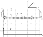
- Fig 1 representing prior art, discloses in a very schematic way a typical temperature distribution over a generic tip plate TP with nozzles NO of a glass fibre bushing after a certain time of production.
- Fig. 1 an x-y-z- coordinate system is added for better illustration of the position and orientation of the various parts of the tip plate and associated construction elements. This coordinate system is valid as well for the other Fig. in this paper.
- Fig. 1a represents a vertical cross section of the sheet-like tip plate in its operational position, being substantially horizontal. Insofar the tip plate extends in the x-y direction of the coordinate system. Walls W extend upwards (in the z-direction) from the tip plate TP.
- the sheet has a substantially (production tolerances neglected) constant thickness (d) in the z-direction and between its upper surface US and its lower surface LS. Electrical contact flanges arranged at opposing wall parts W1, W2 are marked by F1, F2.
- Fig. 1b is a schematic top view onto said tip plate TP.
- a few nozzles are symbolized by circles NO.
- Dotted lines identify five sections A, B, C, D and E between left and right ends E1, E2 of the tip plate (at wall parts W1, W2), wherein sections A and E feature the lowest body temperature ( Fig. 1c : T.A), sections B and D a medium temperature profile, while the center section C is characterized by the highest average temperature ( Fig. 1c : T.C) of all sections A-E.
- the temperature profile and temperature differences between ends E1, E2 are symbolized in Fig. 1c with a maximum temperature difference in this embodiment of around 30-40Kelvin.
- the invention goes a different way in providing a tip plate with different sections of different physical properties and/or different chemical compositions.
- physical properties refers to all structural changes, including sizes, dimensions, geometry, pores, pore distribution, as well as changes in strength.
- chemical composition refers to all changes of materials from which the tip plate is made, in particular alloy changes.
- the tip plate allows to construct the tip plate with sections of different mechanical strength and/or different electrical resistance and/or different thermal conductivity where required. Sections of different properties are arranged next to each other in the x-y- direction of the coordinate system; in other words: Between opposing ends, or in a direction from one end to the other respectively, the tip plate provides adjacent sections of different physical and/or chemical properties.
- This design includes sharp boundaries (2-dimensional faces) between adjacent sections as well as smooth transition zones (3-dimensional) between adjacent sections of different properties to avoid extreme (sudden) changes within small areas of the tip plate.
- section does not refer to asymptotic small areas or just manufacturing tolerances.
- a higher mechanical strength can be achieved, e.g., by a lattice structure (e.g. a grid-like or honey- comb structure) of the respective tip plate (body) section and changes in the thickness of said respective section.
- a lattice structure e.g. a grid-like or honey- comb structure
- One option is to use a material of different mechanical properties (compared with an adjacent section in the x-y- direction) for at least one section of the tip plate.
- At least one section can be made of a material of different thermal conductivity to alter the respective temperature of this section by means of the so called Joule heating effect, known as such to the skilled person.
- sections of the tip plate featuring lower temperatures in known constructions (as sections A and E in Fig. 1 ), may be designed of reduced thickness (seen in the flow direction of the metal melt through the nozzles, which is the z-direction) to increase the amount of heat generated in that section.
- the invention relates to a tip plate for a bushing for receiving a high-temperature melt as defined in claim 1, comprising - in its operational position - an upper surface, which extends in an x-y-direction of the coordinate system, a lower surface at a distance to the upper surface and a body in between, as well as a multiplicity of nozzle like through-openings, extending at least between the upper surface and the lower surface, through which the melt may leave the bushing in a z- direction of the coordinate system, wherein at least two sections of the tip plate, adjoining each other in the x-y-direction of the coordinate system, have different physical properties, different chemical compositions or both.
- the individual sections of the tip plate can be discrete or feature a gradual transition into one another.
- body defines the part of the tip plate between upper surface and lower surface but does not include the through openings (nozzles, nozzle areas). Similarly the upper surface and/or the lower surface represent additional sections of the tip plate (besides the body).
- the upper surface of the tip plate is a "closed" surface (with the exception of the area of the through openings) to keep the glass melt within in the bushing unless drawn off via said through openings/nozzles.
- the upper surface is continuous and comprises numerous through openings, used as or provided to integrate (discrete) nozzles, which at their lower end may protrude the lower surface of the tip plate.
- the lower surface of the tip plate (bottom of the bushing) is not necessarily closed (in the sense as defined before with respect to the upper surface). This allows to design any sections of the tip plate below its upper surface in a new and favorable pattern, i.e. with different structural features compared with the "solid" prior art design.
- An embodiment provides a tip plate, wherein at least one section is produced by additive manufacturing, also called 3 D printing.
- Additive manufacturing allows the realization of nearly unlimited structural features, e.g. to adapt the physical (in particular structural) properties of the respective section or sections, which will be described in more detail hereinafter.
- the tip plate can be designed in a way that at least 50%, or at least 70%, or at least 85% of its volume are produced by additive manufacturing, which can also be 100%.
- One or more sections can be manufactured separately and then assembled to one common tip plate (e.g. by welding). It is also possible to produce the tip plate (all its sections) in one common additive manufacturing process and thus to achieve one common monolithic tip plate. Both embodiments allow to provide transition zones between adjoining tip plate sections in a bespoke manner as disclosed above.
- Another embodiment of the invention features at least one section below the upper surface with at least one hollow space.
- This hollow space can be a closed pore, a sack pore (depression), which extends from below towards the upper surface, a slit, which extends substantially parallel to the upper surface in or into the tip plate body and/or any other structural means.
- This embodiment includes a design wherein the hollow spaces are arranged between a closed upper surface and a closed lower surface.
- the at least one (further) section below the upper surface features a lattice structure such as a grid-like structure, e.g. a honey-comb structure.
- a lattice structure such as a grid-like structure, e.g. a honey-comb structure.
- this embodiment may also be realized with a closed lower body surface.
- Additive manufacturing allows structures which allow a bespoke design of the respective tip plate for a certain application.
- the corresponding software program can be stored and used again at any time later to produce a 1:1 copy of the section(s) or tip plate, enabling very constant manufacturing conditions with manufacturing tolerances towards zero, even over a very long production time and independently of any replacement of a used tip plate by a new one.
- Sections with structures of reduced density either lead to a reduction of material and costs or may be used to increase the overall thickness of the tip plate (without requiring more material compared with solid prior art constructions) in that section(s) , which also leads to an increase in mechanical strength.
- Another option is to vary the distance between the upper surface and the lower surface of at least one section compared to at least one adjoining (adjacent) section in the x-y-direction of the coordinate system.
- This embodiment is characterized by a tip plate, wherein the distance between the upper surface and the lower surface of at least one section is different to the distance between the upper surface and the lower surface of at least one adjoining section.
- Adjoining sections may be arranged substantially parallel to each other, or as substantially concentric rings, may have border lines which follow an involute profile or an oval shape or any other design, in each case depending on the local conditions.
- the lower surface of the body can be a physically closed surface (as is the upper surface) or a virtual (imaginary) surface in case of hollow structures (grid like structures, honey comb structures etc. or structures featuring depressions from below towards to upper surface) as disclosed.
- At least two adjoining sections can be made of different metal alloys and/or metal alloys of different thermal conductivity to achieve similar results, i.e. different thermal conductivity and/or different structural integrity (e.g. strength) at sections where required.
- one section can be made of a PtRh alloy with 90m-% Platinum and 10m-% Rhodium, while the adjacent section is made of a PtRh alloy of 80m% Platinum and 20m% Rhodium.
- the invention further refers to a bushing for receiving a high-temperature melt, comprising a tip plate as mentioned before and a wall, extending into one common direction from said tip plate, i.e. upwardly in its use (operation) position, substantially corresponding to the z-direction as mentioned before.
- the tip plate may have a rectangular shape in a top view and four wall segments, extending therefrom in the same direction, thus limiting a cuboid space for the melt, wherein the wall segments are tightly connected to the tip plate, e.g. by welding or - to its best - in a common additive manufacturing method.
- At least one section of the tip plate or the tip plate in total can be designed by additive manufacturing, although theoretically structural modifications can also be realized by cutting etc.
- At least two wall segments of the bushing are designed to be connected to or may be connected to an electric power supply to allow heating of the glass melt in the bushing, typically by direct current, although other heating methods are not critical.
- Fig. 2 a vertical cross section of a bushing according to the invention, including embodiments F-J of a tip plate according to invention
- Fig. 3 side and top views according to Fig. 1 of a tip plate according to the invention
- Fig. 4 a further embodiment of a tip plate according to the invention in a cross sectional presentation.
- Fig. 2 displays a bushing BU which comprises a rectangular (bottom) tip plate TP with an upper surface US and a lower surface LS, between which the tip plate TP defines a body BO and through holes designed as corresponding nozzles NO, as well as four side walls, two of which (W1, W2) are displayed, together defining a space for a glass melt GM, present on the upper surface US and extracted therefrom via said nozzles NO (the flow - by gravity - and the flow direction substantially correspond to the z-direction, see attached coordinate system).
- Side wall W1, W2 and tip plate TP are made of a PtRh alloy (90m%Pt, 10m%Rh) and welded to each other.
- Tip plate TP was designed by additive manufacturing, i.e. in a 3D laser printer, by forming one thin layer of a fine alloy powder (particles ⁇ 100 ⁇ m] on top of the other in successive manufacturing steps and melting the powder material by laser beams according to a predefined pattern until the final design has been reached.
- Fig. 2 schematically displays four embodiments of possible designs for the tip plate TP, named F to J, which can be realized individually or in arbitrary combinations, depending on the specific glass melt, electric power and overall sizes of the bushing.
- Section F is characterized as follows: Below the "closed" upper surface US is a section featuring a lattice structure, defined by thin partition walls PW arranged in a zig zag pattern and substantially "open" downwardly, i.e. in this embodiment the lower surface LS of the tip plate is defined by an imaginary surface IS, (generally parallel to the upper surface US), from which depressions extend upwardly, in the z-direction, towards the upper surface US.
- Section F requires ca. 30% less alloy material compared with a solid section, although its mechanical strength is very high.
- the thermal behavior is such that section F achieves a higher temperature compared with a solid plate construction.
- This design may, for example, be used in the hot spot area (C) of a tip plate TP similar to that of Fig. 1 .
- Section G differs from section F by a substantially closed lower surface LS, so that a thickness dG may be defined between upper and lower surface US, LS.
- the body material of section G is characterized by closed pores CP, which lower the density and weight of this section G compared to a throughout solid body material as used in prior art ( Fig. 1 ). The number and size of said pores is only schematic and may be selected according to the local requirements.
- All sections of the tip plate of Fig. 2 can be produced by additive manufacturing, either separately or in one common manufacturing process.
- sections of different properties can follow each other not only in the x-direction as displayed, but alternatively or additionally also in the y-direction.
- Fig. 3 displays the tip plate TP of generally same outer dimensions as that of Fig 1 , but the tip plate of Fig. 3 was produced by additive manufacturing (3D laser printing) and with different structural features in different sections (A-E).
- sections A and E have been modified and now feature relatively large pores to lower the density and thus increase the temperature in that section (under the proviso of same electrical power as according to the embodiment of Fig. 1 ).
- the overall (closed) porosity of these sections A,E is around 20% by volume.
- Adjoining sections B,D in Fig. 3 again differ from sections B, D of Fig. 1 by inner pores, but less than and smaller ones compared to sections A,E, so that the total (closed) porosity of sections B,D being around 10 % by volume.
- the center section C hasn't been changed between the embodiments of Fig. 1 and 3 .
- the different structural features of the tip plate TP of Fig. 3 compared with that of Fig. 1 , shows, that the tip plate TP of Fig. 3 features a substantially constant temperature profile (symbolized in Fig. 3c as T.A-E) between ends E1 and E2 (walls W1, W2), namely a temperature similar to that of section C in Fig. 1 .
- Fig. 4a displays a very basic improvement over prior art according to Fig. 1 in that just the thickness of the tip plate TP is varied between opposite ends at W1,W2. While the shape of the upper surface US of the tip plate corresponds to that according to Fig. 1 , the lower surface LS of the embodiment in Fig. 4 is designed in a curved way. Thickness dA in section A is the lowest and increases substantially continuously towards section C, which thickness dC being the largest in that embodiment (dC being ca. 1,5 dA)and then decreases again towards sections D and E, with dD being slightly larger (ca. 15%) than dA.
- the temperature distribution within the tip plate TP can be homogenized as displayed in Fig. 4b .
- this embodiment is represented by a convex shape (curved, arched, cambered shape) of the lower surface and/or the upper surface of the tip plate in any/all direction(s) of the coordinate system.
- the tip plate may also feature a curved upper surface in the y-direction (and not only in the x-direction as shown).
- a smooth surface without steps is preferred to achieve a most homogeneous temperature distribution and strength within a tip plate of this embodiment defined by variations in its thickness. Further features of the invention as disclosed in connection with Fig. 2 , 3 may also be integrated into this embodiment.
- Nozzles NO in all Figures have been displayed in a highly schematic way for better illustration. Typically up to 8000 nozzles (tips) are arranged within one tip plate.
Landscapes
- Engineering & Computer Science (AREA)
- Chemical & Material Sciences (AREA)
- Manufacturing & Machinery (AREA)
- Materials Engineering (AREA)
- Life Sciences & Earth Sciences (AREA)
- General Life Sciences & Earth Sciences (AREA)
- Geochemistry & Mineralogy (AREA)
- Organic Chemistry (AREA)
- Manufacture, Treatment Of Glass Fibers (AREA)
Claims (15)
- Plaque d'extrémité (TP) pour une filière (BU) destinée à recevoir une masse fondue (GM) à haute température, comprenant - dans sa position opérationnelle - une surface supérieure (US), qui s'étend dans une direction x-y du système de coordonnées, une surface inférieure (LS) à une distance (d) de la surface supérieure (US) et un corps (BO) entre elles, ainsi qu'une multiplicité de d'ouvertures traversantes (NO) analogues à des buses, s'étendant au moins entre la surface supérieure (US) et la surface inférieure (LS), à travers lesquelles la masse fondue (GM) peut quitter la filière (BU) dans une direction z du système de coordonnées, dans laquelle au moins deux sections (A-B, B-C, C-D, D-E, F-G, G-H, H-J) de la plaque d'extrémité (TP), adjacentes l'une à l'autre dans la direction x-y du système de coordonnées, ont des propriétés physiques différentes, une composition chimique différente ou les deux de sorte qu'une distribution de température à l'intérieur de la plaque d'extrémité (TP) soit homogénéisée sur la superficie complète.
- Plaque d'extrémité (TP) selon la revendication 1, dans laquelle au moins une section (A...J) est un produit de fabrication additif.
- Plaque d'extrémité (TP) selon la revendication 2, au moins 50 % de son volume étant un produit de fabrication additif.
- Plaque d'extrémité (TP) selon la revendication 1, dans laquelle la surface supérieure (US) est une surface fermée à l'exception des zones des ouvertures traversantes (NO).
- Plaque d'extrémité (TP) selon la revendication 1, dans laquelle au moins une dépression (DE) s'étend à partir de la surface inférieure (LS) d'au moins une section (F) jusque dans le corps (BO).
- Plaque d'extrémité (TP) selon la revendication 1, dans laquelle au moins une section (A, B, D, E, G, H) au-dessous de la surface supérieure (US) présente au moins un espace creux (CP).
- Plaque d'extrémité (TP) selon la revendication 1, dans laquelle au moins une section (F) au-dessous de la surface supérieure (US) présente une structure en treillis.
- Plaque d'extrémité (TP) selon la revendication 1, dans laquelle la distance (dJ) entre la surface supérieure (US) et la surface inférieure (LS) d'au moins une section (J) est différente de la distance (dH) entre la surface supérieure (US) et la surface inférieure (LS) d'au moins une section adjacente (H).
- Plaque d'extrémité (TP) selon la revendication 1, dans laquelle au moins deux sections adjacentes sont constituées d'alliages métalliques différents.
- Plaque d'extrémité (TP) selon la revendication 1, comprenant au moins quatre-vingt-dix pour cent en masse d'un alliage PtRh.
- Filière (BU) pour recevoir une masse fondue (GM) à haute température, comprenant une plaque d'extrémité (TP) selon la revendication 1 et au moins une paroi (W1,2), s'étendant à partir de ladite plaque d'extrémité (TP) dans la direction z.
- Filière (BU) selon la revendication 11, dans laquelle la plaque d'extrémité (TP) a une forme rectangulaire dans une vue de dessus et quatre segments de paroi (W1, W2) s'étendant à partir de celle-ci dans la même direction, limitant ainsi un espace cuboïde pour la masse fondue (GM), les segments de paroi (W1, W2) étant étroitement raccordés à la plaque d'extrémité (TP).
- Filière (BU) selon la revendication 11, avec au moins deux segments de paroi (W1, W2) agencés à distance l'un de l'autre et raccordés à une alimentation électrique (F1, F2).
- Filière (BU) selon la revendication 10, dans laquelle au moins une section (A...J) de la plaque d'extrémité (TP) est un produit de fabrication additif.
- Filière (BU) selon la revendication 10 avec une plaque d'extrémité (TP) qui est un produit de fabrication additif.
Applications Claiming Priority (1)
| Application Number | Priority Date | Filing Date | Title |
|---|---|---|---|
| PCT/EP2019/086511 WO2021121614A1 (fr) | 2019-12-20 | 2019-12-20 | Plaque d'extrémité et filière correspondante |
Publications (2)
| Publication Number | Publication Date |
|---|---|
| EP4077228A1 EP4077228A1 (fr) | 2022-10-26 |
| EP4077228B1 true EP4077228B1 (fr) | 2025-02-19 |
Family
ID=69063786
Family Applications (1)
| Application Number | Title | Priority Date | Filing Date |
|---|---|---|---|
| EP19829575.0A Active EP4077228B1 (fr) | 2019-12-20 | 2019-12-20 | Plaque d'extrémité et filière correspondante |
Country Status (7)
| Country | Link |
|---|---|
| US (1) | US20230015763A1 (fr) |
| EP (1) | EP4077228B1 (fr) |
| JP (1) | JP7611254B2 (fr) |
| KR (1) | KR20220120565A (fr) |
| CN (1) | CN114945538A (fr) |
| CA (1) | CA3162931A1 (fr) |
| WO (1) | WO2021121614A1 (fr) |
Families Citing this family (2)
| Publication number | Priority date | Publication date | Assignee | Title |
|---|---|---|---|---|
| WO2022229472A1 (fr) * | 2021-07-21 | 2022-11-03 | Cookson Precious Metals Ltd. | Ensemble ailette de refroidissement pour une filière dans la production de fibre de verre réalisée par fabrication additive |
| WO2022229473A1 (fr) * | 2021-07-21 | 2022-11-03 | Cookson Precious Metals Ltd. | Ensemble ailette de refroidissement pour une filière dans la production de fibre de verre |
Family Cites Families (21)
| Publication number | Priority date | Publication date | Assignee | Title |
|---|---|---|---|---|
| DE1023860B (de) * | 1954-07-07 | 1958-02-06 | Guido Gollrad Dipl Ing | Duesenplatte zum Ziehen von Fasern aus erhitztem Glas od. dgl. |
| US3736116A (en) * | 1971-07-20 | 1973-05-29 | Owens Corning Fiberglass Corp | Method and apparatus for manufacturing continuous filaments |
| CA1125515A (fr) * | 1978-05-08 | 1982-06-15 | Hiroaki Shono | Plaque a orifices pour tete de filage du verre |
| JPS594388B2 (ja) * | 1978-05-08 | 1984-01-30 | 日東紡績株式会社 | ガラス繊維製造用紡糸炉におけるオリフイスプレ−ト |
| FR2505811B1 (fr) * | 1981-05-14 | 1985-06-14 | Saint Gobain Vetrotex | Perfectionnements apportes a la fabrication des fibres de verre |
| JPS60103047A (ja) * | 1983-11-01 | 1985-06-07 | Tanaka Kikinzoku Kogyo Kk | ガラス繊維製造用ブツシングプレ−ト |
| US4612027A (en) * | 1985-08-29 | 1986-09-16 | Owens-Corning Fiberglas Corporation | Method and apparatus for forming glass fibers |
| JP2947293B2 (ja) * | 1990-12-29 | 1999-09-13 | 株式会社徳力本店 | 繊維形成用ブッシングの製造方法 |
| JPH05139772A (ja) * | 1991-11-14 | 1993-06-08 | Central Glass Co Ltd | 複合ガラス繊維並びにその製造装置 |
| US6196029B1 (en) * | 1994-10-27 | 2001-03-06 | Johns Manville International, Inc. | Low profile bushing for making fibers |
| JP2002128538A (ja) * | 2000-10-18 | 2002-05-09 | Nitto Boseki Co Ltd | ガラス繊維用ブッシング |
| JP2008044801A (ja) * | 2006-08-11 | 2008-02-28 | Nippon Electric Glass Co Ltd | ガラス繊維製造装置とガラス繊維の製造方法 |
| CN101506113B (zh) * | 2006-08-23 | 2012-09-19 | 日本电气硝子株式会社 | 连续玻璃纤维制造用漏板及其制造方法、以及连续玻璃纤维制造装置及使用其的连续玻璃纤维的制造方法 |
| CN102190437A (zh) * | 2010-03-12 | 2011-09-21 | 赣州联银复合材料有限公司 | 玻璃纤维拉丝用拱形底板漏板 |
| EP2676937A1 (fr) * | 2012-06-21 | 2013-12-25 | 3B-Fibreglass SPRL | Module de plaque d'extrémité polygonale et ensemble filière comprenant de tels modules |
| WO2014001173A1 (fr) * | 2012-06-26 | 2014-01-03 | Umicore Ag & Co. Kg | Plaque de base |
| CN204417339U (zh) * | 2015-02-13 | 2015-06-24 | 宁波求新新材料科技有限公司 | 漏板 |
| US20160312338A1 (en) * | 2015-04-27 | 2016-10-27 | John Hart Miller | High hot creep resistant alloys, parts, systems and methods |
| EP3216545B2 (fr) * | 2016-03-07 | 2022-09-28 | Heraeus Deutschland GmbH & Co. KG | Poudre en metal noble et son utilisation pour la fabrication de composants |
| CN106242266B (zh) * | 2016-08-25 | 2019-03-15 | 巨石集团有限公司 | 用于短切玻璃纤维生产的漏板及短切玻璃纤维生产方法 |
| CN208346026U (zh) * | 2018-06-27 | 2019-01-08 | 四川省玻纤集团有限公司 | 一种玄武岩纤维熔融池窑 |
-
2019
- 2019-12-20 WO PCT/EP2019/086511 patent/WO2021121614A1/fr not_active Ceased
- 2019-12-20 CN CN201980103158.2A patent/CN114945538A/zh active Pending
- 2019-12-20 EP EP19829575.0A patent/EP4077228B1/fr active Active
- 2019-12-20 KR KR1020227020432A patent/KR20220120565A/ko not_active Ceased
- 2019-12-20 CA CA3162931A patent/CA3162931A1/fr active Pending
- 2019-12-20 JP JP2022538432A patent/JP7611254B2/ja active Active
- 2019-12-20 US US17/786,702 patent/US20230015763A1/en not_active Abandoned
Also Published As
| Publication number | Publication date |
|---|---|
| US20230015763A1 (en) | 2023-01-19 |
| CN114945538A (zh) | 2022-08-26 |
| JP2023514479A (ja) | 2023-04-06 |
| WO2021121614A1 (fr) | 2021-06-24 |
| CA3162931A1 (fr) | 2021-06-24 |
| JP7611254B2 (ja) | 2025-01-09 |
| KR20220120565A (ko) | 2022-08-30 |
| EP4077228A1 (fr) | 2022-10-26 |
Similar Documents
| Publication | Publication Date | Title |
|---|---|---|
| EP4077228B1 (fr) | Plaque d'extrémité et filière correspondante | |
| US20160312338A1 (en) | High hot creep resistant alloys, parts, systems and methods | |
| EP2114833B1 (fr) | Appareil et procédé de traitement de verre fondu | |
| CA2680037A1 (fr) | Ensemble de douille a alliage multiple | |
| EP2129631A1 (fr) | Fonds de filière au palladium pour ensemble douille | |
| TW200817296A (en) | Bushing assembly having cooling support fins | |
| US3511306A (en) | Method and apparatus for centrifugally casting perforated rings | |
| JP4673275B2 (ja) | フュージョンダウンドロー法による板ガラスの製造方法 | |
| AU718550B2 (en) | Method for making a strengthened spinner having integrally formed ribs | |
| JP6036192B2 (ja) | 板ガラスの成形ノズル | |
| CA2401091C (fr) | Filiere pourvue d'une borne et procede de fabrication de cette filiere | |
| US5846284A (en) | Spinner with eyelets having multiple orifices | |
| RU2599518C2 (ru) | Устройство, выдающее стеклянные волокна, с уменьшенным содержанием драгоценных металлов | |
| CN104603075A (zh) | 底板 | |
| JP7592850B2 (ja) | ブッシング用チッププレート及びブッシング | |
| JP7739865B2 (ja) | ガラス繊維の製造装置、及びガラス繊維の製造方法 | |
| CN102596834A (zh) | 喷丝口装置 | |
| EP2041038A1 (fr) | Dispositif et procédé de fabrication de fibres minérales | |
| JP7207593B2 (ja) | ブッシング、及びガラス繊維の製造方法 | |
| CN120943513A (zh) | 用于修改熔融玻璃流的设备和方法 | |
| WO2023204733A1 (fr) | Procédé de fabrication d'un dispositif pour produire la fibre de verre ou de basalte | |
| EP2527306A1 (fr) | Filières transversales présentant des supports en céramique |
Legal Events
| Date | Code | Title | Description |
|---|---|---|---|
| STAA | Information on the status of an ep patent application or granted ep patent |
Free format text: STATUS: UNKNOWN |
|
| STAA | Information on the status of an ep patent application or granted ep patent |
Free format text: STATUS: THE INTERNATIONAL PUBLICATION HAS BEEN MADE |
|
| PUAI | Public reference made under article 153(3) epc to a published international application that has entered the european phase |
Free format text: ORIGINAL CODE: 0009012 |
|
| STAA | Information on the status of an ep patent application or granted ep patent |
Free format text: STATUS: REQUEST FOR EXAMINATION WAS MADE |
|
| 17P | Request for examination filed |
Effective date: 20220718 |
|
| AK | Designated contracting states |
Kind code of ref document: A1 Designated state(s): AL AT BE BG CH CY CZ DE DK EE ES FI FR GB GR HR HU IE IS IT LI LT LU LV MC MK MT NL NO PL PT RO RS SE SI SK SM TR |
|
| DAV | Request for validation of the european patent (deleted) | ||
| DAX | Request for extension of the european patent (deleted) | ||
| STAA | Information on the status of an ep patent application or granted ep patent |
Free format text: STATUS: EXAMINATION IS IN PROGRESS |
|
| 17Q | First examination report despatched |
Effective date: 20231009 |
|
| RIC1 | Information provided on ipc code assigned before grant |
Ipc: B33Y 80/00 20150101ALI20240827BHEP Ipc: C03B 37/092 20060101ALI20240827BHEP Ipc: C03B 37/08 20060101ALI20240827BHEP Ipc: C03B 37/095 20060101ALI20240827BHEP Ipc: C03B 37/083 20060101AFI20240827BHEP |
|
| GRAP | Despatch of communication of intention to grant a patent |
Free format text: ORIGINAL CODE: EPIDOSNIGR1 |
|
| STAA | Information on the status of an ep patent application or granted ep patent |
Free format text: STATUS: GRANT OF PATENT IS INTENDED |
|
| INTG | Intention to grant announced |
Effective date: 20241004 |
|
| GRAS | Grant fee paid |
Free format text: ORIGINAL CODE: EPIDOSNIGR3 |
|
| GRAA | (expected) grant |
Free format text: ORIGINAL CODE: 0009210 |
|
| STAA | Information on the status of an ep patent application or granted ep patent |
Free format text: STATUS: THE PATENT HAS BEEN GRANTED |
|
| AK | Designated contracting states |
Kind code of ref document: B1 Designated state(s): AL AT BE BG CH CY CZ DE DK EE ES FI FR GB GR HR HU IE IS IT LI LT LU LV MC MK MT NL NO PL PT RO RS SE SI SK SM TR |
|
| REG | Reference to a national code |
Ref country code: GB Ref legal event code: FG4D |
|
| REG | Reference to a national code |
Ref country code: CH Ref legal event code: EP |
|
| REG | Reference to a national code |
Ref country code: IE Ref legal event code: FG4D |
|
| REG | Reference to a national code |
Ref country code: DE Ref legal event code: R096 Ref document number: 602019066258 Country of ref document: DE |
|
| REG | Reference to a national code |
Ref country code: NL Ref legal event code: MP Effective date: 20250219 |
|
| PG25 | Lapsed in a contracting state [announced via postgrant information from national office to epo] |
Ref country code: RS Free format text: LAPSE BECAUSE OF FAILURE TO SUBMIT A TRANSLATION OF THE DESCRIPTION OR TO PAY THE FEE WITHIN THE PRESCRIBED TIME-LIMIT Effective date: 20250519 |
|
| PG25 | Lapsed in a contracting state [announced via postgrant information from national office to epo] |
Ref country code: FI Free format text: LAPSE BECAUSE OF FAILURE TO SUBMIT A TRANSLATION OF THE DESCRIPTION OR TO PAY THE FEE WITHIN THE PRESCRIBED TIME-LIMIT Effective date: 20250219 |
|
| PG25 | Lapsed in a contracting state [announced via postgrant information from national office to epo] |
Ref country code: PL Free format text: LAPSE BECAUSE OF FAILURE TO SUBMIT A TRANSLATION OF THE DESCRIPTION OR TO PAY THE FEE WITHIN THE PRESCRIBED TIME-LIMIT Effective date: 20250219 |
|
| PG25 | Lapsed in a contracting state [announced via postgrant information from national office to epo] |
Ref country code: ES Free format text: LAPSE BECAUSE OF FAILURE TO SUBMIT A TRANSLATION OF THE DESCRIPTION OR TO PAY THE FEE WITHIN THE PRESCRIBED TIME-LIMIT Effective date: 20250219 |
|
| REG | Reference to a national code |
Ref country code: LT Ref legal event code: MG9D |
|
| PG25 | Lapsed in a contracting state [announced via postgrant information from national office to epo] |
Ref country code: NO Free format text: LAPSE BECAUSE OF FAILURE TO SUBMIT A TRANSLATION OF THE DESCRIPTION OR TO PAY THE FEE WITHIN THE PRESCRIBED TIME-LIMIT Effective date: 20250519 Ref country code: IS Free format text: LAPSE BECAUSE OF FAILURE TO SUBMIT A TRANSLATION OF THE DESCRIPTION OR TO PAY THE FEE WITHIN THE PRESCRIBED TIME-LIMIT Effective date: 20250619 |
|
| PG25 | Lapsed in a contracting state [announced via postgrant information from national office to epo] |
Ref country code: NL Free format text: LAPSE BECAUSE OF FAILURE TO SUBMIT A TRANSLATION OF THE DESCRIPTION OR TO PAY THE FEE WITHIN THE PRESCRIBED TIME-LIMIT Effective date: 20250219 |
|
| PG25 | Lapsed in a contracting state [announced via postgrant information from national office to epo] |
Ref country code: HR Free format text: LAPSE BECAUSE OF FAILURE TO SUBMIT A TRANSLATION OF THE DESCRIPTION OR TO PAY THE FEE WITHIN THE PRESCRIBED TIME-LIMIT Effective date: 20250219 |
|
| PG25 | Lapsed in a contracting state [announced via postgrant information from national office to epo] |
Ref country code: LV Free format text: LAPSE BECAUSE OF FAILURE TO SUBMIT A TRANSLATION OF THE DESCRIPTION OR TO PAY THE FEE WITHIN THE PRESCRIBED TIME-LIMIT Effective date: 20250219 Ref country code: PT Free format text: LAPSE BECAUSE OF FAILURE TO SUBMIT A TRANSLATION OF THE DESCRIPTION OR TO PAY THE FEE WITHIN THE PRESCRIBED TIME-LIMIT Effective date: 20250620 |
|
| PG25 | Lapsed in a contracting state [announced via postgrant information from national office to epo] |
Ref country code: GR Free format text: LAPSE BECAUSE OF FAILURE TO SUBMIT A TRANSLATION OF THE DESCRIPTION OR TO PAY THE FEE WITHIN THE PRESCRIBED TIME-LIMIT Effective date: 20250520 Ref country code: BG Free format text: LAPSE BECAUSE OF FAILURE TO SUBMIT A TRANSLATION OF THE DESCRIPTION OR TO PAY THE FEE WITHIN THE PRESCRIBED TIME-LIMIT Effective date: 20250219 |
|
| REG | Reference to a national code |
Ref country code: AT Ref legal event code: MK05 Ref document number: 1768156 Country of ref document: AT Kind code of ref document: T Effective date: 20250219 |
|
| PG25 | Lapsed in a contracting state [announced via postgrant information from national office to epo] |
Ref country code: SE Free format text: LAPSE BECAUSE OF FAILURE TO SUBMIT A TRANSLATION OF THE DESCRIPTION OR TO PAY THE FEE WITHIN THE PRESCRIBED TIME-LIMIT Effective date: 20250219 |
|
| PG25 | Lapsed in a contracting state [announced via postgrant information from national office to epo] |
Ref country code: SM Free format text: LAPSE BECAUSE OF FAILURE TO SUBMIT A TRANSLATION OF THE DESCRIPTION OR TO PAY THE FEE WITHIN THE PRESCRIBED TIME-LIMIT Effective date: 20250219 |
|
| PG25 | Lapsed in a contracting state [announced via postgrant information from national office to epo] |
Ref country code: DK Free format text: LAPSE BECAUSE OF FAILURE TO SUBMIT A TRANSLATION OF THE DESCRIPTION OR TO PAY THE FEE WITHIN THE PRESCRIBED TIME-LIMIT Effective date: 20250219 |
|
| PG25 | Lapsed in a contracting state [announced via postgrant information from national office to epo] |
Ref country code: IT Free format text: LAPSE BECAUSE OF FAILURE TO SUBMIT A TRANSLATION OF THE DESCRIPTION OR TO PAY THE FEE WITHIN THE PRESCRIBED TIME-LIMIT Effective date: 20250219 |
|
| PG25 | Lapsed in a contracting state [announced via postgrant information from national office to epo] |
Ref country code: AT Free format text: LAPSE BECAUSE OF FAILURE TO SUBMIT A TRANSLATION OF THE DESCRIPTION OR TO PAY THE FEE WITHIN THE PRESCRIBED TIME-LIMIT Effective date: 20250219 |
|
| PG25 | Lapsed in a contracting state [announced via postgrant information from national office to epo] |
Ref country code: CZ Free format text: LAPSE BECAUSE OF FAILURE TO SUBMIT A TRANSLATION OF THE DESCRIPTION OR TO PAY THE FEE WITHIN THE PRESCRIBED TIME-LIMIT Effective date: 20250219 Ref country code: EE Free format text: LAPSE BECAUSE OF FAILURE TO SUBMIT A TRANSLATION OF THE DESCRIPTION OR TO PAY THE FEE WITHIN THE PRESCRIBED TIME-LIMIT Effective date: 20250219 |
|
| PG25 | Lapsed in a contracting state [announced via postgrant information from national office to epo] |
Ref country code: RO Free format text: LAPSE BECAUSE OF FAILURE TO SUBMIT A TRANSLATION OF THE DESCRIPTION OR TO PAY THE FEE WITHIN THE PRESCRIBED TIME-LIMIT Effective date: 20250219 |
|
| PG25 | Lapsed in a contracting state [announced via postgrant information from national office to epo] |
Ref country code: SK Free format text: LAPSE BECAUSE OF FAILURE TO SUBMIT A TRANSLATION OF THE DESCRIPTION OR TO PAY THE FEE WITHIN THE PRESCRIBED TIME-LIMIT Effective date: 20250219 |
|
| REG | Reference to a national code |
Ref country code: DE Ref legal event code: R097 Ref document number: 602019066258 Country of ref document: DE |
|
| PLBE | No opposition filed within time limit |
Free format text: ORIGINAL CODE: 0009261 |
|
| STAA | Information on the status of an ep patent application or granted ep patent |
Free format text: STATUS: NO OPPOSITION FILED WITHIN TIME LIMIT |
|
| 26N | No opposition filed |
Effective date: 20251120 |