EP4078082B1 - Dispositif de mesure pour mesurer la longueur de profilés d'étanchéité - Google Patents
Dispositif de mesure pour mesurer la longueur de profilés d'étanchéité Download PDFInfo
- Publication number
- EP4078082B1 EP4078082B1 EP20855883.3A EP20855883A EP4078082B1 EP 4078082 B1 EP4078082 B1 EP 4078082B1 EP 20855883 A EP20855883 A EP 20855883A EP 4078082 B1 EP4078082 B1 EP 4078082B1
- Authority
- EP
- European Patent Office
- Prior art keywords
- measuring
- sealing profile
- measuring device
- measuring tape
- application head
- Prior art date
- Legal status (The legal status is an assumption and is not a legal conclusion. Google has not performed a legal analysis and makes no representation as to the accuracy of the status listed.)
- Active
Links
Images


Classifications
-
- G—PHYSICS
- G01—MEASURING; TESTING
- G01B—MEASURING LENGTH, THICKNESS OR SIMILAR LINEAR DIMENSIONS; MEASURING ANGLES; MEASURING AREAS; MEASURING IRREGULARITIES OF SURFACES OR CONTOURS
- G01B21/00—Measuring arrangements or details thereof, where the measuring technique is not covered by the other groups of this subclass, unspecified or not relevant
- G01B21/02—Measuring arrangements or details thereof, where the measuring technique is not covered by the other groups of this subclass, unspecified or not relevant for measuring length, width, or thickness
- G01B21/06—Measuring arrangements or details thereof, where the measuring technique is not covered by the other groups of this subclass, unspecified or not relevant for measuring length, width, or thickness specially adapted for measuring length or width of objects while moving
-
- G—PHYSICS
- G01—MEASURING; TESTING
- G01B—MEASURING LENGTH, THICKNESS OR SIMILAR LINEAR DIMENSIONS; MEASURING ANGLES; MEASURING AREAS; MEASURING IRREGULARITIES OF SURFACES OR CONTOURS
- G01B5/00—Measuring arrangements characterised by the use of mechanical techniques
- G01B5/02—Measuring arrangements characterised by the use of mechanical techniques for measuring length, width or thickness
- G01B5/04—Measuring arrangements characterised by the use of mechanical techniques for measuring length, width or thickness specially adapted for measuring length or width of objects while moving
- G01B5/043—Measuring arrangements characterised by the use of mechanical techniques for measuring length, width or thickness specially adapted for measuring length or width of objects while moving for measuring length
-
- G—PHYSICS
- G01—MEASURING; TESTING
- G01B—MEASURING LENGTH, THICKNESS OR SIMILAR LINEAR DIMENSIONS; MEASURING ANGLES; MEASURING AREAS; MEASURING IRREGULARITIES OF SURFACES OR CONTOURS
- G01B7/00—Measuring arrangements characterised by the use of electric or magnetic techniques
- G01B7/02—Measuring arrangements characterised by the use of electric or magnetic techniques for measuring length, width or thickness
- G01B7/026—Measuring arrangements characterised by the use of electric or magnetic techniques for measuring length, width or thickness for measuring length of cable, band or the like, which has been paid out, e.g. from a reel
Definitions
- the invention relates to an application head of a sealing profile application device with a measuring device for measuring the length of sealing profiles.
- the background of the invention is that a sealing profile can be pulled from a reel/reel or a depot or buffer by means of sealing profile application devices by feeding it using a transport device and applied to a body part using an application roller in accordance with the specifications.
- the sealing profile is provided with an adhesive surface for this purpose, whereby the adhesive surface is covered with a separating tape - hereinafter referred to as a liner - which is only pulled off/removed immediately before the sealing profile is applied to the body part.
- a further background of the invention is that the device is intended to measure or record both the expansion and the compression of the sealing profile rubber.
- the body part to be applied can be divided into different segments.
- the specified value of the compression or expansion can be different in each segment.
- the actual length per segment can be determined using the measuring device for length measurement. This enables a segment-by-segment evaluation of the compression or expansion of the sealing profile.
- Various measuring devices are known which are intended to measure the length of the sealing profile advanced by the transport device in a sealing profile application device.
- measuring devices are known which, as in DE 20216704 U1 disclosed, which are intended for the length measurement of hoses, cables or pipes.
- the measuring device is implemented by an endless member, such as a belt, rotating over deflection rollers.
- an endless member such as a belt, rotating over deflection rollers.
- a rotating endless member is driven and thus serves to advance the object to be measured and a second, oppositely arranged, rotating endless member is used for length measurement.
- the object of the invention is to provide an application head of a sealing profile application device with a measuring device that makes it possible to measure the length of sealing profile rubbers to be applied to vehicle body parts.
- the length measurement should be as precise as possible. Accordingly, slippage between the sealing profile and the measuring system should be avoided.
- the invention relates to an application head of a sealing profile application device with a measuring device for measuring the length of sealing profiles.
- the measuring device comprises a measuring tape running over at least two rollers, whereby the measuring tape and/or at least one of the rollers interact with a measurement value acquisition system.
- a transport device with a conveyor belt running over rollers is arranged opposite the measuring tape. Between the The sealing profile is moved/pushed forward by the conveyor belt between the rotating measuring tape and the rotating conveyor belt.
- the measuring tape is moved by the movement of the sealing profile. This movement preferably takes place without tension or inhibition, so that slip-free measurement is promoted.
- the object of the invention is achieved with the features of claim 1.
- the measuring device - and thus also the oppositely arranged transport device - are arranged in an application head of the sealing profile application device and that a measuring tape contact area of the sealing profile with the measuring tape extends longer than a conveyor belt contact area of the sealing profile with the conveyor belt.
- the profile seal is fed to the application head without stretching.
- the measuring device is arranged in the application head so that this takes place immediately before the targeted compression of the sealing profile. This allows the actual length of the sealing profile to be measured without stretching or compression.
- the measuring contact area extends longer than the transport contact area.
- the longer measuring contact area generates a larger contact surface. This results in a longer or more extensive adhesion of the measuring tape to the liner. Slippage is thus almost impossible, so that the measurement result is much more accurate than with known measuring devices.
- Another advantage is that the sealing profile is not affected by teeth, as in claim 18 of the publication WO 2016030131 A1 suggested, is damaged.
- the measuring tape has a smooth, elastic and/or adhesive surface on the side facing a liner of the sealing profile.
- a liner is a separating tape that is applied to the adhesive surface of the sealing profile to protect it and to prevent unwanted adhesions. The liner is removed immediately before the profile rubber is applied and glued to the body part.
- the smooth, elastic and/or adhesive surface of the measuring tape ensures good adhesion of the measuring tape to the liner on the sealing profile in the contact area of the measuring tape with the sealing profile. Accordingly, slippage between the liner and the measuring tape can be minimized/almost eliminated and the length of the sealing profile can be determined with the highest precision.
- the adhesive effect is achieved by a suitable/advantageous combination of the materials used for the liner and the surface of the measuring tape.
- the side of the measuring tape facing the liner of the sealing profile is made, for example, of the materials rubber and/or polyurethane.
- the materials mentioned as examples are smooth, elastic and/or have an adhesive surface. This makes them particularly suitable for ensuring good adhesion between the measuring tape and the liner, thus enabling slip-free and therefore precise length measurements.
- the pressure roller and, if applicable, the other guide and pressure elements press the sealing profile onto the measuring tape, so that an adhesive connection between the measuring tape and the liner can be achieved in the entire measuring contact area.
- the effective measuring contact area is thus increased by the protrusion area compared to the transport contact area.
- the pressure roller has a circumferential profile on the casing side.
- the profile on the casing side of the pressure roller is concave. This allows the transported sealing profile to be guided sideways.
- the side guidance of the sealing profile ensures precise alignment of the sealing profile on the measuring tape and thus good adhesion in the measuring contact area.
- the other guide and pressure elements can also be profiled accordingly and thus achieve the effects described above.
- the profile of the pressure roller running around the casing corresponds to the profile of the sealing profile running on the pressure roller. This ensures that even pressure is applied without the sealing profile being deformed. The sealing profile is thus pressed evenly onto the measuring tape, which has the advantage of ensuring good adhesion to the measuring tape.
- the measuring device is connected to the transport device and/or the transport device is connected to the measuring device by means of at least one Displacement device is arranged to be movable transversely to the transport direction of the sealing profile.
- the sliding device allows the contact pressure of the measuring tape and the conveyor belt as well as the pressure roller on the sealing profile to be varied. The higher the contact pressure, the better the adhesion. It also makes it possible to adapt the device to sealing profiles of different thicknesses.
- the pressure roller and/or other guide and pressure elements can be arranged so that they can be moved together with the conveyor device or separately in order to ensure that the profile sealing rubber is guided evenly and that the pressure is evenly applied to the measuring tape.
- the displacement of the measuring device and the transport device takes place to the same extent relative to one another.
- the center line of the sealing profile thus remains unchanged, so that the positioning of other guide elements of the application head does not have to be adjusted.
- the measured value acquisition system is designed as a rotary encoder, in particular as a rotary incremental encoder.
- the rotary incremental encoder is preferably integrated into a deflection roller and detects the angle of rotation of the deflection roller very precisely, such as with at least 200 pulses per revolution, such as 2000 pulses per revolution.
- the angle of rotation is proportional to the distance covered by the measuring tape.
- the angle of rotation of the deflection roller is detected by a sensor and forwarded to the evaluation unit.
- the rotary encoder, in particular rotary incremental encoder thus determines the length of the advancing measuring tape, which corresponds to the length of the advanced sealing profile when slippage is avoided according to the invention.
- a rotary incremental encoder integrated into the pulley offers a very cost-effective solution for recording the length measurement data.
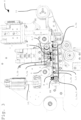
- the Figure 1 shows a perspective side view of an application head 5 of a sealing profile application device (not shown) with a measuring device 1 and a transport device 6 for the sealing profile 2 to be applied.
- the sealing profile 2 is made of rubber and designed as a hollow profile.
- the side of the sealing profile 2 that is to be glued to the body part (not shown) is provided with an adhesive surface provided, the adhesive surface being covered with a plastic tape 2a serving as a separating tape, a so-called liner 2a, until immediately before gluing.
- the sealing profile 2 is pulled off a spool/reel (not shown) by means of the transport device 6 and pushed forward to an application roller 11, by means of which the sealing profile 2 is glued/applied to the body part (not shown) 1.
- the transport device 6 here comprises two deflection rollers 3a and two support rollers 3b, over which an endless conveyor belt 7 rotates.
- the conveyor belt 7 is designed as a coated toothed belt, similar to the measuring tape 4.
- the coating is specially tailored to the surface quality of the sealing profile 2.
- the conveyor belt 7 presses against the sealing profile 2 in a transport contact area KT on a side of the sealing profile 2 arranged opposite the liner 2a, so that in the transport contact area KT a static friction is caused between the conveyor belt 7 and the sealing profile 2, which leads to the sealing profile 2 being carried along by the conveyor belt 7 and thus being pushed forward to the application roller 11.
- the sealing profile 2 is pushed forward from left to right.
- the measuring tape 4 of the measuring device 1, which is arranged opposite the conveyor belt 7, serves as a counter-hold for the conveyor belt 7.
- the conveyor belt 7 in turn serves as a counter-hold for the measuring tape 4. This ensures that both the measuring tape 4 and the conveyor belt 7 are pressed against the sealing profile.
- the self-contained measuring tape 4 runs over associated deflection rollers 3a.
- support rollers 3b are arranged on the measuring tape 4, which are arranged along the measuring tape contact area KM in order to press the measuring tape 4 onto the sealing profile 2 in the entire measuring tape contact area KM and thus enable the measuring tape 4 to adhere to the sealing profile 2 with as little slippage as possible.
- the endless measuring tape 4 is also designed as a coated toothed belt, with the coating being arranged on the side facing the liner 2a.
- the surface of the measuring tape 4 is accordingly elastic and smooth.
- the material combination of the surface of the measuring tape 4 with that of the liner 2a achieves an adhesive and thus bonding effect. This allows the sealing profile 2 to move the measuring tape 4 while avoiding slippage.
- the measuring device 1 is designed in such a way that a minimized resistance is achieved due to the smooth running rollers 3a, 3b of the measuring device 1. This low resistance can easily be overcome by the adhesion.
- the measurement data acquisition is carried out by a rotary incremental encoder 5, which is integrated into one of the deflection rollers 3a of the measuring device 1.
- the rotary incremental encoder 5 is able to record the angle of rotation of the relevant deflection roller 3a, which is proportional to the rotation path of the measuring tape 4 and thus to the length of the advanced sealing profile 2.
- An evaluation unit (not shown) determines the length of the advanced sealing profile 2 from the angle of rotation. When a cut is made in the sealing profile 2, a length measurement ends and a new length measurement begins.
- the measuring tape contact area KM is significantly longer than the transport contact area KT.
- the longer measuring tape contact area advantageously results in a larger contact surface and thus a greater adhesion of the measuring tape to the liner. This virtually eliminates slippage, so that the measurement result is much more accurate than with known measuring devices.
- the sealing profile cannot be formed by teeth, as in claim 18 of the publication WO 2016030131 A1 suggested, be damaged.
- a pressure roller 9 is arranged opposite the measuring tape 4.
- the opposite pressure roller 9 ensures that the sealing profile 2 exerts counter pressure on the measuring tape 4 in the projection area Ü, which advantageously improves the adhesion to the liner.
- other pressure and guide elements can also be arranged with equivalent effect.
- the application head 8 is designed such that the measuring device 1 can be moved relative to the transport device 6 by means of a displacement device 10 designed as a hydraulic cylinder 10.
- a displacement device 10 designed as a hydraulic cylinder 10.
- the measuring tape 4 is preferably designed with a smooth, elastic and thus adhesive surface on the outside, on which it comes into contact with the liner 2a of the sealing profile 2. Rubber, for example, is used as a particularly suitable material here. In this way, the measuring tape 4 can adhere well to the sealing profile 2 in the measuring contact area KM and thus prevent slippage. Accordingly, the length of the advanced sealing profile 2 can be measured with the highest precision.
- the Figure 2 shows a perspective side view of an application head 8 of a sealing profile application device with a measuring device 1 and a transport device 6 as well as a sealing profile 2 to be transported and measured.
- the illustration is as far as Fig.1
- the difference is that no pressure roller is provided here.
- the pressure of the sealing profile 2 on the measuring tape 4 in the overhang area Ü is carried out here in that the sealing profile 2 is fed in at an angle from below and is thus pressed against the measuring tape 4 in the area of the first deflection roller 3a.
- the representation thus corresponds to the embodiment according to claim 1.
- FIG 3 is a perspective side view of an application head 8 of a sealing profile application device with a measuring device 1, a transport device 6 and a pressure roller 9. Accordingly, in Fig.3 which from Fig.1 known design is shown without the sealing profile being shown here.
- the Figure 4 represents a perspective side view of an application head 8 of a sealing profile application device with a measuring device 1 and a transport device 6.
- the Figure 5 shows a sectional view through the measuring tape 4 and the sealing profile 2 with the deflection roller 3a of the measuring device 1 and the pressure roller 9.
- the frictional contact between the measuring tape 4 and the sealing profile 2 is achieved on the one hand by the fact that the measuring tape 4 and the sealing profile 2 are pressed together by the compressive arrangement of the deflection roller 3a and the pressure roller 9.
- a liner 2a is arranged on the side of the sealing profile 2 facing the measuring tape 4 to protect the adhesive surface underneath.
- the adhesive friction between the measuring tape 4 and the sealing profile 2 is increased by the surface of the measuring tape 4 being provided with an adhesive coating 4a.
- the adhesive coating 4a is designed in such a way that an adhesive effect is brought about on the surface of the liner 2a, which improves the adhesive friction between the measuring tape 4 and the sealing profile 2.
- the pressure roller 9 is profiled on the casing side in the same way as the side of the sealing profile 2 that is in contact with it.
- the sealing profile 2 is thus evenly pressed against the measuring tape 4.
- the sealing profile 2 is advantageously not deformed. Due to the profiling, the sealing profile 2 is also advantageously guided laterally in the application head.
Landscapes
- Physics & Mathematics (AREA)
- General Physics & Mathematics (AREA)
- Length Measuring Devices With Unspecified Measuring Means (AREA)
- Length Measuring Devices By Optical Means (AREA)
- Length-Measuring Instruments Using Mechanical Means (AREA)
- Adhesives Or Adhesive Processes (AREA)
- A Measuring Device Byusing Mechanical Method (AREA)
Claims (9)
- Tête d'application (8) d'un dispositif d'application de profilés d'étanchéité, la tête d'application (8) présentant un dispositif de mesure (1) pour mesurer la longueur de profilés d'étanchéité (2),le dispositif de mesure (1) comprenant une bande de mesure (4) circulant sur au moins deux rouleaux (3a, 3b), au moins l'un des rouleaux (3a, 3b)coopérant avec un système de saisie des valeurs de mesure (5) en tant que capteur rotatif (5),un dispositif de transport (6) avec une bande transporteuse (7) circulant sur des rouleaux (3a, 3b) étant disposé en face de la bande de mesure (4), le profilé d'étanchéité pouvant être déplacé ou avancé par la bande transporteuse entre la bande de mesure en circulation et la bande de transport en circulation, et la bande de mesure pouvant être déplacée en même temps par le mouvement du profilé d'étanchéité,une zone de contact de bande de mesure (KM) du profilé d'étanchéité (2) avec la bande de mesure (4) s'étend plus longtemps d'une partie en saillie (Ü)qu'une zone de contact de transport (KT) du profilé d'étanchéité (2) avec la bande de transport (7) et en ce qu'en face de la partie en saillie (Ü) de la bande de mesure (4), sur le côté de la bande transporteuse (7), est disposé au moins un rouleau de pression (9) ou sont disposés d'autres éléments de guidage et de pression (9).
- Tête d'application avec dispositif de mesure selon la revendication 1,
caractérisé en ce que
la bande de mesure (4) présente une surface lisse, élastique et/ou adhésive (4a) sur le côté tourné vers un liner (2a) du profilé d'étanchéité (2). - Tête d'application avec dispositif de mesure selon la revendication 2,
caractérisé en ce que
le côté de la bande de mesure (4a) tourné vers le liner (2a) du profilé d'étanchéité (2) est réalisé avec du caoutchouc et/ou du polyuréthane. - Tête d'application avec dispositif de mesure selon la revendication 1,
caractérisé en ce que
le rouleau de pression (9) et / ou les autres éléments de guidage et de pression présentent un profilé périphérique du côté de l'enveloppe. - Tête d'application avec dispositif de mesure selon la revendication 4,
caractérisé en ce que
le profilé (P) du rouleau de pression (9) et / ou les autres éléments de guidage et de pression (9) sont concaves. - Tête d'application avec dispositif de mesure selon la revendication 4 ou 5,
caractérisé en ce que
le profilé (P) du rouleau de pression (9) et/ou les autres éléments de guidage et de pression (9) correspondent au profilé adjacent du profilé d'étanchéité (2). - Tête d'application avec dispositif de mesure selon l'une des revendications précédentes,
caractérisé en ce quele dispositif de mesure (1) est monté par rapport au dispositif de transport (6), avec ou sans le rouleau de pression (9) ou les autres éléments de guidage et de pression (9).
et/oule dispositif de transport (6), avec ou sans le rouleau de pression (9) et/ou les autres éléments de guidage et de pression (9), sont/seront disposés de manière à pouvoir être déplacés par rapport au dispositif de mesure (1) au moyen d'au moins un dispositif de déplacement (10). - Tête d'application avec dispositif de mesure selon la revendication 7,
caractérisé en ce que
le déplacement du dispositif de mesure (1) et du dispositif de transport (6) s'effectue dans la même mesure. - Tête d'application avec dispositif de mesure selon l'une des revendications précédentes,
caractérisé en ce que
le système de saisie de valeurs de mesure (5) est conçu comme un capteur rotatif (5), en particulier comme un capteur incrémental rotatif (5), et est disposé dans un rouleau (3a, 3b) .
Applications Claiming Priority (2)
| Application Number | Priority Date | Filing Date | Title |
|---|---|---|---|
| DE102019135647 | 2019-12-20 | ||
| PCT/DE2020/101081 WO2021121488A1 (fr) | 2019-12-20 | 2020-12-18 | Dispositif de mesure pour mesurer la longueur de profilés d'étanchéité |
Publications (2)
| Publication Number | Publication Date |
|---|---|
| EP4078082A1 EP4078082A1 (fr) | 2022-10-26 |
| EP4078082B1 true EP4078082B1 (fr) | 2024-09-11 |
Family
ID=74701346
Family Applications (1)
| Application Number | Title | Priority Date | Filing Date |
|---|---|---|---|
| EP20855883.3A Active EP4078082B1 (fr) | 2019-12-20 | 2020-12-18 | Dispositif de mesure pour mesurer la longueur de profilés d'étanchéité |
Country Status (10)
| Country | Link |
|---|---|
| US (1) | US12152876B2 (fr) |
| EP (1) | EP4078082B1 (fr) |
| CN (1) | CN114829873A (fr) |
| DE (1) | DE102020134309A1 (fr) |
| ES (1) | ES2997249T3 (fr) |
| HU (1) | HUE069826T2 (fr) |
| MX (1) | MX2022007743A (fr) |
| PL (1) | PL4078082T3 (fr) |
| WO (1) | WO2021121488A1 (fr) |
| ZA (1) | ZA202205736B (fr) |
Family Cites Families (20)
| Publication number | Priority date | Publication date | Assignee | Title |
|---|---|---|---|---|
| US3829976A (en) * | 1971-12-30 | 1974-08-20 | A Moore | Metering device for indicating the length of flat flexible material |
| AT381168B (de) * | 1982-05-12 | 1986-09-10 | List Hans | Einrichtung zur ueberpruefung der riemenspannung |
| GB8428235D0 (en) * | 1984-11-08 | 1984-12-19 | Bicc Plc | Length measurement |
| EP0496049B1 (fr) | 1991-01-21 | 1995-05-17 | Ttc Technology Trading Company | Perfectionnement au dispositif pour l'alimentation d'un câble dans un automate pour façonner des câbles |
| JPH087058B2 (ja) * | 1993-04-19 | 1996-01-29 | 昭和電機株式会社 | 長尺体の計尺装置 |
| US5936398A (en) * | 1997-02-28 | 1999-08-10 | Denharco Inc. | Measuring roller system with sensor error correction |
| GB0107900D0 (en) * | 2001-03-29 | 2001-05-23 | Post Office | Improvements in monitoring systems |
| AT6510U1 (de) | 2002-08-29 | 2003-11-25 | Taferner Marko | Vorrichtung zum messen von längen |
| JP4682846B2 (ja) * | 2005-12-27 | 2011-05-11 | ブラザー工業株式会社 | 画像形成装置 |
| US8466380B2 (en) * | 2008-11-27 | 2013-06-18 | Teraoka Seiko Co., Ltd. | Apparatus and method for measuring articles including conveyor-weighers supported on weighing unit |
| JP5428891B2 (ja) * | 2010-01-21 | 2014-02-26 | 富士ゼロックス株式会社 | 測長装置および画像形成装置 |
| US8839949B2 (en) * | 2012-04-13 | 2014-09-23 | John Bean Technologies Corporation | Determination and correction of conveyor belt speed/location |
| DE112013005893T5 (de) * | 2012-12-10 | 2015-09-24 | Bando Chemical Industries, Ltd. | Eigenschwingungsmessvorrichtung |
| DE102014112185A1 (de) | 2014-08-26 | 2016-03-03 | Grohmann Engineering Gmbh | Verfahren und Vorrichtung zur Bestimmung der Dehnung und/oder Stauchung eines Dichtungsprofils |
| KR102480036B1 (ko) * | 2017-05-02 | 2022-12-21 | 라이트람, 엘엘씨 | 컨베이어 벨트용 용량성 결합 센서 시스템 |
| JP6641513B2 (ja) * | 2018-04-06 | 2020-02-05 | 三ツ星ベルト株式会社 | はす歯ベルトおよびベルト伝動装置 |
| US11235934B2 (en) * | 2020-09-19 | 2022-02-01 | Devika Kataria | Smart monitoring of belt tension and slip |
| EP4001695A1 (fr) * | 2020-11-20 | 2022-05-25 | Manuel Lindner | Réglage et surveillance automatiques d'un entraînement par courroie |
| US12037201B2 (en) * | 2021-12-07 | 2024-07-16 | Laitram, L.L.C. | Measuring conveyor belt stretch |
| US12000415B1 (en) * | 2023-06-30 | 2024-06-04 | Liftwave, Inc. | Pneumatic operation and self-alignment of linear actuator |
-
2020
- 2020-12-18 ES ES20855883T patent/ES2997249T3/es active Active
- 2020-12-18 WO PCT/DE2020/101081 patent/WO2021121488A1/fr not_active Ceased
- 2020-12-18 HU HUE20855883A patent/HUE069826T2/hu unknown
- 2020-12-18 MX MX2022007743A patent/MX2022007743A/es unknown
- 2020-12-18 CN CN202080088335.7A patent/CN114829873A/zh active Pending
- 2020-12-18 EP EP20855883.3A patent/EP4078082B1/fr active Active
- 2020-12-18 PL PL20855883.3T patent/PL4078082T3/pl unknown
- 2020-12-18 US US17/787,341 patent/US12152876B2/en active Active
- 2020-12-18 DE DE102020134309.4A patent/DE102020134309A1/de active Pending
-
2022
- 2022-05-24 ZA ZA2022/05736A patent/ZA202205736B/en unknown
Also Published As
| Publication number | Publication date |
|---|---|
| EP4078082A1 (fr) | 2022-10-26 |
| CN114829873A (zh) | 2022-07-29 |
| ES2997249T3 (en) | 2025-02-14 |
| US12152876B2 (en) | 2024-11-26 |
| PL4078082T3 (pl) | 2025-02-17 |
| HUE069826T2 (hu) | 2025-04-28 |
| US20230019401A1 (en) | 2023-01-19 |
| DE102020134309A1 (de) | 2021-06-24 |
| WO2021121488A1 (fr) | 2021-06-24 |
| ZA202205736B (en) | 2023-01-25 |
| MX2022007743A (es) | 2022-08-18 |
Similar Documents
| Publication | Publication Date | Title |
|---|---|---|
| EP1813562B1 (fr) | Procédé et dispositif destinés à l'application d'un joint | |
| EP2067645B1 (fr) | Procédé et dispositif d'application de joints d'étanchéité | |
| EP1477789A2 (fr) | Dispositif de mesure pour une bande en movement logitudinale et procédé de mesure des parametres de processus du transport de la bande | |
| DE4446308A1 (de) | Vorrichtung zum Auftragen eines flüssigen oder pastösen Mediums auf eine laufende Materialbahn | |
| EP4078082B1 (fr) | Dispositif de mesure pour mesurer la longueur de profilés d'étanchéité | |
| DE102016221271A1 (de) | Verfahren und Vorrichtung zum Anbringen einer flexiblen Dichtung an dem Umfang eines Bauteils | |
| DE102006032138B4 (de) | Verfahren und Vorrichtung zum Applizieren einer Dichtung | |
| DE102011050750B4 (de) | Verfahren und Vorrichtung zum Anbringen und Abschneiden eines Dichtungsprofils | |
| DE102011050751A1 (de) | Vorrichtung zum Anbringen eines Dichtungsprofils | |
| EP1225143A2 (fr) | Méthode et dispositif pour enrouler continuellement une bande de matériau fibreux | |
| EP1225142B2 (fr) | Méthode et dispositif pour enrouler continuellement une bande de matériau fibreux | |
| DE4429091C1 (de) | Verfahren und Einzugsvorrichtung für Dichtprofile | |
| DE3231965A1 (de) | Vorrichtung zur messung des dickenprofils bandfoermigen materials | |
| EP3420307B1 (fr) | Dispositif de mesure pour déterminer une longueur partielle d'un élément allongé en mouvement | |
| DE102017223736B4 (de) | Messgeräteträger zur vermessung einer verlegten schiene | |
| EP4155662B1 (fr) | Agencement de mesure de l'épaisseur d'une bande continue de matière | |
| DE19950175A1 (de) | Zylindrische Rotationswalze, insbesondere Anlage- und/oder Breitstreckwalze für den Wickelvorgang von bahnförmigen Materialien, z.B. Folienbahnen | |
| DE2632997A1 (de) | Zentriereinrichtung an buchbindereimaschinen zum mittigen teilen von buechern o.dgl. | |
| DE102004018981A1 (de) | Breitstreckwalze zum faltenfreien Führen von Folien und Warenbahnen mittels Spreizelementen | |
| DE19515652C2 (de) | Vorrichtung zur Kontrolle der Länge und der Lage eines Kapitalbandes | |
| CH536778A (de) | Vorrichtung zum Verlegen von Dichtungsstreifen | |
| EP0965684A2 (fr) | Dispositif d'application de materiau fluide ou pâteux sur un bande en mouvement | |
| DE2827080A1 (de) | Vorrichtung zum bespinnen von kabeln und anderem strangfoermigem gut mit baendern | |
| DE3828995A1 (de) | Laengsteilanlage fuer metallband | |
| DE1931882A1 (de) | Bandtransporteinrichtung |
Legal Events
| Date | Code | Title | Description |
|---|---|---|---|
| STAA | Information on the status of an ep patent application or granted ep patent |
Free format text: STATUS: UNKNOWN |
|
| STAA | Information on the status of an ep patent application or granted ep patent |
Free format text: STATUS: THE INTERNATIONAL PUBLICATION HAS BEEN MADE |
|
| PUAI | Public reference made under article 153(3) epc to a published international application that has entered the european phase |
Free format text: ORIGINAL CODE: 0009012 |
|
| STAA | Information on the status of an ep patent application or granted ep patent |
Free format text: STATUS: REQUEST FOR EXAMINATION WAS MADE |
|
| 17P | Request for examination filed |
Effective date: 20220719 |
|
| AK | Designated contracting states |
Kind code of ref document: A1 Designated state(s): AL AT BE BG CH CY CZ DE DK EE ES FI FR GB GR HR HU IE IS IT LI LT LU LV MC MK MT NL NO PL PT RO RS SE SI SK SM TR |
|
| DAV | Request for validation of the european patent (deleted) | ||
| DAX | Request for extension of the european patent (deleted) | ||
| P01 | Opt-out of the competence of the unified patent court (upc) registered |
Effective date: 20230524 |
|
| GRAP | Despatch of communication of intention to grant a patent |
Free format text: ORIGINAL CODE: EPIDOSNIGR1 |
|
| STAA | Information on the status of an ep patent application or granted ep patent |
Free format text: STATUS: GRANT OF PATENT IS INTENDED |
|
| INTG | Intention to grant announced |
Effective date: 20240408 |
|
| GRAS | Grant fee paid |
Free format text: ORIGINAL CODE: EPIDOSNIGR3 |
|
| GRAA | (expected) grant |
Free format text: ORIGINAL CODE: 0009210 |
|
| STAA | Information on the status of an ep patent application or granted ep patent |
Free format text: STATUS: THE PATENT HAS BEEN GRANTED |
|
| AK | Designated contracting states |
Kind code of ref document: B1 Designated state(s): AL AT BE BG CH CY CZ DE DK EE ES FI FR GB GR HR HU IE IS IT LI LT LU LV MC MK MT NL NO PL PT RO RS SE SI SK SM TR |
|
| REG | Reference to a national code |
Ref country code: GB Ref legal event code: FG4D Free format text: NOT ENGLISH |
|
| REG | Reference to a national code |
Ref country code: CH Ref legal event code: EP |
|
| REG | Reference to a national code |
Ref country code: DE Ref legal event code: R096 Ref document number: 502020009233 Country of ref document: DE |
|
| REG | Reference to a national code |
Ref country code: IE Ref legal event code: FG4D Free format text: LANGUAGE OF EP DOCUMENT: GERMAN |
|
| REG | Reference to a national code |
Ref country code: SE Ref legal event code: TRGR |
|
| REG | Reference to a national code |
Ref country code: LT Ref legal event code: MG9D |
|
| PG25 | Lapsed in a contracting state [announced via postgrant information from national office to epo] |
Ref country code: NO Free format text: LAPSE BECAUSE OF FAILURE TO SUBMIT A TRANSLATION OF THE DESCRIPTION OR TO PAY THE FEE WITHIN THE PRESCRIBED TIME-LIMIT Effective date: 20241211 |
|
| REG | Reference to a national code |
Ref country code: NL Ref legal event code: MP Effective date: 20240911 |
|
| PG25 | Lapsed in a contracting state [announced via postgrant information from national office to epo] |
Ref country code: GR Free format text: LAPSE BECAUSE OF FAILURE TO SUBMIT A TRANSLATION OF THE DESCRIPTION OR TO PAY THE FEE WITHIN THE PRESCRIBED TIME-LIMIT Effective date: 20241212 Ref country code: FI Free format text: LAPSE BECAUSE OF FAILURE TO SUBMIT A TRANSLATION OF THE DESCRIPTION OR TO PAY THE FEE WITHIN THE PRESCRIBED TIME-LIMIT Effective date: 20240911 |
|
| PG25 | Lapsed in a contracting state [announced via postgrant information from national office to epo] |
Ref country code: BG Free format text: LAPSE BECAUSE OF FAILURE TO SUBMIT A TRANSLATION OF THE DESCRIPTION OR TO PAY THE FEE WITHIN THE PRESCRIBED TIME-LIMIT Effective date: 20240911 |
|
| PG25 | Lapsed in a contracting state [announced via postgrant information from national office to epo] |
Ref country code: LV Free format text: LAPSE BECAUSE OF FAILURE TO SUBMIT A TRANSLATION OF THE DESCRIPTION OR TO PAY THE FEE WITHIN THE PRESCRIBED TIME-LIMIT Effective date: 20240911 |
|
| PG25 | Lapsed in a contracting state [announced via postgrant information from national office to epo] |
Ref country code: HR Free format text: LAPSE BECAUSE OF FAILURE TO SUBMIT A TRANSLATION OF THE DESCRIPTION OR TO PAY THE FEE WITHIN THE PRESCRIBED TIME-LIMIT Effective date: 20240911 |
|
| PG25 | Lapsed in a contracting state [announced via postgrant information from national office to epo] |
Ref country code: RS Free format text: LAPSE BECAUSE OF FAILURE TO SUBMIT A TRANSLATION OF THE DESCRIPTION OR TO PAY THE FEE WITHIN THE PRESCRIBED TIME-LIMIT Effective date: 20241211 |
|
| REG | Reference to a national code |
Ref country code: SK Ref legal event code: T3 Ref document number: E 45507 Country of ref document: SK |
|
| PG25 | Lapsed in a contracting state [announced via postgrant information from national office to epo] |
Ref country code: RS Free format text: LAPSE BECAUSE OF FAILURE TO SUBMIT A TRANSLATION OF THE DESCRIPTION OR TO PAY THE FEE WITHIN THE PRESCRIBED TIME-LIMIT Effective date: 20241211 Ref country code: NO Free format text: LAPSE BECAUSE OF FAILURE TO SUBMIT A TRANSLATION OF THE DESCRIPTION OR TO PAY THE FEE WITHIN THE PRESCRIBED TIME-LIMIT Effective date: 20241211 Ref country code: LV Free format text: LAPSE BECAUSE OF FAILURE TO SUBMIT A TRANSLATION OF THE DESCRIPTION OR TO PAY THE FEE WITHIN THE PRESCRIBED TIME-LIMIT Effective date: 20240911 Ref country code: HR Free format text: LAPSE BECAUSE OF FAILURE TO SUBMIT A TRANSLATION OF THE DESCRIPTION OR TO PAY THE FEE WITHIN THE PRESCRIBED TIME-LIMIT Effective date: 20240911 Ref country code: GR Free format text: LAPSE BECAUSE OF FAILURE TO SUBMIT A TRANSLATION OF THE DESCRIPTION OR TO PAY THE FEE WITHIN THE PRESCRIBED TIME-LIMIT Effective date: 20241212 Ref country code: FI Free format text: LAPSE BECAUSE OF FAILURE TO SUBMIT A TRANSLATION OF THE DESCRIPTION OR TO PAY THE FEE WITHIN THE PRESCRIBED TIME-LIMIT Effective date: 20240911 Ref country code: BG Free format text: LAPSE BECAUSE OF FAILURE TO SUBMIT A TRANSLATION OF THE DESCRIPTION OR TO PAY THE FEE WITHIN THE PRESCRIBED TIME-LIMIT Effective date: 20240911 |
|
| REG | Reference to a national code |
Ref country code: ES Ref legal event code: FG2A Ref document number: 2997249 Country of ref document: ES Kind code of ref document: T3 Effective date: 20250214 |
|
| PG25 | Lapsed in a contracting state [announced via postgrant information from national office to epo] |
Ref country code: NL Free format text: LAPSE BECAUSE OF FAILURE TO SUBMIT A TRANSLATION OF THE DESCRIPTION OR TO PAY THE FEE WITHIN THE PRESCRIBED TIME-LIMIT Effective date: 20240911 |
|
| PG25 | Lapsed in a contracting state [announced via postgrant information from national office to epo] |
Ref country code: IS Free format text: LAPSE BECAUSE OF FAILURE TO SUBMIT A TRANSLATION OF THE DESCRIPTION OR TO PAY THE FEE WITHIN THE PRESCRIBED TIME-LIMIT Effective date: 20250111 Ref country code: PT Free format text: LAPSE BECAUSE OF FAILURE TO SUBMIT A TRANSLATION OF THE DESCRIPTION OR TO PAY THE FEE WITHIN THE PRESCRIBED TIME-LIMIT Effective date: 20250113 |
|
| PG25 | Lapsed in a contracting state [announced via postgrant information from national office to epo] |
Ref country code: SM Free format text: LAPSE BECAUSE OF FAILURE TO SUBMIT A TRANSLATION OF THE DESCRIPTION OR TO PAY THE FEE WITHIN THE PRESCRIBED TIME-LIMIT Effective date: 20240911 Ref country code: RO Free format text: LAPSE BECAUSE OF FAILURE TO SUBMIT A TRANSLATION OF THE DESCRIPTION OR TO PAY THE FEE WITHIN THE PRESCRIBED TIME-LIMIT Effective date: 20240911 |
|
| PG25 | Lapsed in a contracting state [announced via postgrant information from national office to epo] |
Ref country code: EE Free format text: LAPSE BECAUSE OF FAILURE TO SUBMIT A TRANSLATION OF THE DESCRIPTION OR TO PAY THE FEE WITHIN THE PRESCRIBED TIME-LIMIT Effective date: 20240911 |
|
| PG25 | Lapsed in a contracting state [announced via postgrant information from national office to epo] |
Ref country code: IT Free format text: LAPSE BECAUSE OF FAILURE TO SUBMIT A TRANSLATION OF THE DESCRIPTION OR TO PAY THE FEE WITHIN THE PRESCRIBED TIME-LIMIT Effective date: 20240911 |
|
| REG | Reference to a national code |
Ref country code: HU Ref legal event code: AG4A Ref document number: E069826 Country of ref document: HU |
|
| REG | Reference to a national code |
Ref country code: DE Ref legal event code: R097 Ref document number: 502020009233 Country of ref document: DE |
|
| PG25 | Lapsed in a contracting state [announced via postgrant information from national office to epo] |
Ref country code: MC Free format text: LAPSE BECAUSE OF FAILURE TO SUBMIT A TRANSLATION OF THE DESCRIPTION OR TO PAY THE FEE WITHIN THE PRESCRIBED TIME-LIMIT Effective date: 20240911 |
|
| PG25 | Lapsed in a contracting state [announced via postgrant information from national office to epo] |
Ref country code: DK Free format text: LAPSE BECAUSE OF FAILURE TO SUBMIT A TRANSLATION OF THE DESCRIPTION OR TO PAY THE FEE WITHIN THE PRESCRIBED TIME-LIMIT Effective date: 20240911 |
|
| PLBE | No opposition filed within time limit |
Free format text: ORIGINAL CODE: 0009261 |
|
| STAA | Information on the status of an ep patent application or granted ep patent |
Free format text: STATUS: NO OPPOSITION FILED WITHIN TIME LIMIT |
|
| REG | Reference to a national code |
Ref country code: CH Ref legal event code: PL |
|
| PG25 | Lapsed in a contracting state [announced via postgrant information from national office to epo] |
Ref country code: LU Free format text: LAPSE BECAUSE OF NON-PAYMENT OF DUE FEES Effective date: 20241218 |
|
| 26N | No opposition filed |
Effective date: 20250612 |
|
| REG | Reference to a national code |
Ref country code: BE Ref legal event code: MM Effective date: 20241231 |
|
| PG25 | Lapsed in a contracting state [announced via postgrant information from national office to epo] |
Ref country code: BE Free format text: LAPSE BECAUSE OF NON-PAYMENT OF DUE FEES Effective date: 20241231 |
|
| PG25 | Lapsed in a contracting state [announced via postgrant information from national office to epo] |
Ref country code: CH Free format text: LAPSE BECAUSE OF NON-PAYMENT OF DUE FEES Effective date: 20241231 |
|
| PG25 | Lapsed in a contracting state [announced via postgrant information from national office to epo] |
Ref country code: IE Free format text: LAPSE BECAUSE OF NON-PAYMENT OF DUE FEES Effective date: 20241218 |
|
| PGFP | Annual fee paid to national office [announced via postgrant information from national office to epo] |
Ref country code: GB Payment date: 20251218 Year of fee payment: 6 |
|
| PGFP | Annual fee paid to national office [announced via postgrant information from national office to epo] |
Ref country code: AT Payment date: 20260113 Year of fee payment: 5 |
|
| PGFP | Annual fee paid to national office [announced via postgrant information from national office to epo] |
Ref country code: FR Payment date: 20251218 Year of fee payment: 6 |
|
| PGFP | Annual fee paid to national office [announced via postgrant information from national office to epo] |
Ref country code: SE Payment date: 20251217 Year of fee payment: 6 |
|
| PGFP | Annual fee paid to national office [announced via postgrant information from national office to epo] |
Ref country code: CZ Payment date: 20251209 Year of fee payment: 6 |
|
| PGFP | Annual fee paid to national office [announced via postgrant information from national office to epo] |
Ref country code: PL Payment date: 20251210 Year of fee payment: 6 |
|
| PGFP | Annual fee paid to national office [announced via postgrant information from national office to epo] |
Ref country code: SK Payment date: 20251217 Year of fee payment: 6 |
|
| PGFP | Annual fee paid to national office [announced via postgrant information from national office to epo] |
Ref country code: HU Payment date: 20260114 Year of fee payment: 6 |
|
| PGFP | Annual fee paid to national office [announced via postgrant information from national office to epo] |
Ref country code: ES Payment date: 20260119 Year of fee payment: 6 |
|
| PGFP | Annual fee paid to national office [announced via postgrant information from national office to epo] |
Ref country code: DE Payment date: 20251222 Year of fee payment: 6 |
|
| REG | Reference to a national code |
Ref country code: DE Ref legal event code: R082 Ref document number: 502020009233 Country of ref document: DE Representative=s name: RAUSCHENBACH + SCHIED PATENTANWAELTE PARTG MBB, DE |