EP4155662B1 - Agencement de mesure de l'épaisseur d'une bande continue de matière - Google Patents
Agencement de mesure de l'épaisseur d'une bande continue de matière Download PDFInfo
- Publication number
- EP4155662B1 EP4155662B1 EP21198570.0A EP21198570A EP4155662B1 EP 4155662 B1 EP4155662 B1 EP 4155662B1 EP 21198570 A EP21198570 A EP 21198570A EP 4155662 B1 EP4155662 B1 EP 4155662B1
- Authority
- EP
- European Patent Office
- Prior art keywords
- material web
- sensor
- contact body
- arrangement
- cylindrical contact
- Prior art date
- Legal status (The legal status is an assumption and is not a legal conclusion. Google has not performed a legal analysis and makes no representation as to the accuracy of the status listed.)
- Active
Links
Images


Classifications
-
- G—PHYSICS
- G01—MEASURING; TESTING
- G01B—MEASURING LENGTH, THICKNESS OR SIMILAR LINEAR DIMENSIONS; MEASURING ANGLES; MEASURING AREAS; MEASURING IRREGULARITIES OF SURFACES OR CONTOURS
- G01B11/00—Measuring arrangements characterised by the use of optical techniques
- G01B11/02—Measuring arrangements characterised by the use of optical techniques for measuring length, width or thickness
- G01B11/06—Measuring arrangements characterised by the use of optical techniques for measuring length, width or thickness for measuring thickness ; e.g. of sheet material
- G01B11/0691—Measuring arrangements characterised by the use of optical techniques for measuring length, width or thickness for measuring thickness ; e.g. of sheet material of objects while moving
-
- B—PERFORMING OPERATIONS; TRANSPORTING
- B65—CONVEYING; PACKING; STORING; HANDLING THIN OR FILAMENTARY MATERIAL
- B65H—HANDLING THIN OR FILAMENTARY MATERIAL, e.g. SHEETS, WEBS, CABLES
- B65H16/00—Unwinding, paying-out webs
- B65H16/02—Supporting web roll
- B65H16/021—Multiple web roll supports
- B65H16/023—Multiple web roll supports rotatable
-
- G—PHYSICS
- G01—MEASURING; TESTING
- G01B—MEASURING LENGTH, THICKNESS OR SIMILAR LINEAR DIMENSIONS; MEASURING ANGLES; MEASURING AREAS; MEASURING IRREGULARITIES OF SURFACES OR CONTOURS
- G01B5/00—Measuring arrangements characterised by the use of mechanical techniques
- G01B5/0002—Arrangements for supporting, fixing or guiding the measuring instrument or the object to be measured
Definitions
- a method for producing a plastic film in which molten plastic material is discharged from a flat nozzle in a conveying direction and subsequently cooled, the flat nozzle having a number of nozzle bolts next to one another in the width direction of the plastic film, with which the size of the discharge gap of the molten plastic material can be influenced, a measuring device for measuring the thickness of the plastic film produced being arranged behind the flat nozzle in the conveying direction.
- the measuring device for measuring the thickness of the film is arranged behind the lifting roller in the conveying direction. This arrangement has the disadvantage that the film is freely suspended without a support device at the measuring location and this can lead to vibrations or flickering, which can falsify the measurement result.
- the invention is therefore based on the object of improving a device or a method for measuring a film thickness in such a way that it provides a more accurate measurement result.
- the cylindrical contact body has a cavity in which the second sensor is accommodated.
- the invention therefore has the advantage that the film is supported by the contact body in the area of the thickness measurement and therefore vibrations in the film are avoided and that, by simultaneously measuring the film thickness on the top and bottom of the film, influencing variables induced by the contact body are automatically calculated out.
- the contact body has a flat contact area.
- the contact body has a contact area that is convex at least in sections. In particular, it is provided that the underside of the material web is guided past the surface of the contact body in the contact area.
- the material web is deflected by the contact area to a predetermined extent so that the material web encloses an angle of greater than 0° before and after the contact area.
- the material web is supported in the area of the thickness measurement at least in sections, in particular by the contact body.
- the material web can in particular be a flexible, elastic and/or coated film.
- the area of the thickness measurement can be defined by the overlapping detection areas of the opposing sensors directed towards each other. It can be provided that a plurality of opposing sensor pairs are arranged across the width of the material web. In this case, it can be provided in particular that one sensor of each sensor pair is arranged at least in sections below the contact area between the material web and the contact body.
- the sensors are designed to measure a distance. It can be provided that the first sensor is designed to detect the distance between the first sensor and the top of the material web and the second sensor is designed to detect the distance between the second sensor and the underside of the material web. It can be provided that the first sensor and the second sensor are arranged at a predetermined distance from each other. The thickness of the material web can thus be calculated from the difference between the predetermined distance between the sensors and the sum of the two measured distances of the first and second sensors.
- the second sensor overlaps at least partially with a cross-sectional area of the cylindrical contact body and is arranged between a rotation axis and the surface of the cylindrical contact body. It can be provided that the second sensor is arranged completely within the cross-sectional area of the cylindrical rolling body.
- the detection area of the second sensor at least partially encompasses an underside of the contact body, in particular an inner surface of the cylindrical contact body. It can be provided that a detection device of the second sensor points in the direction of the underside of the contact body or the inner surface. It can be provided that a detection device of the first sensor is directed towards the top of the material web. It can be provided that the detection areas of the first and second sensors are exactly opposite each other.
- the cavity can be dimensioned such that the second sensor can be arranged statically in the cylindrical rolling body without coming into contact with the cylindrical rolling body rotating around the second sensor.
- the cylindrical rolling body can be designed in the shape of a sleeve.
- the cylindrical rolling body can be rotatably mounted so that the moving material web rolls on it, in particular without slippage.
- the cylindrical rolling body can be manufactured galvanically.
- the surface of the cylindrical contact body has at least one opening that is at least partially located in the detection range of the second sensor. It can be provided that the material web is guided past the opening. It can be provided that the opening opens into the cavity.
- the opening extends essentially tangentially along the surface of the cylindrical contact body.
- the opening can extend in the direction of movement of the material web along the material web guided past the opening.
- the opening can have a width of greater than 0.5 cm. It can be provided that the openings are recesses in the material of the cylindrical rolling body.
- the opening extends with at least one interruption around the entire circumference of the cylindrical contact body. It can be provided that the opening has two, three or four interruptions, in particular regularly spaced from one another. The openings distributed over the circumference in this way can each have the same length.
- An interruption can be characterized in that at least one web made of the material of the cylindrical rolling body is provided in this area, by means of which the structure of the cylindrical rolling body is stabilized.
- the surface of the cylindrical contact body has a plurality of parallel, spaced-apart openings.
- the distances between the openings can be the same.
- the openings can be spaced apart from one another by web-shaped spacer elements. It can be provided that the openings have a greater width than the web-shaped spacer elements.
- the surface of the contact body, in particular of the cylindrical rolling body has a sieve structure.
- the sieve structure can have a plurality of openings, in particular regularly distributed on the surface of the contact body, in particular of the cylindrical rolling body.
- the openings can be elongated.
- the openings can be circular.
- the openings can be oval.
- the openings can be angular.
- the openings can be quadrangular.
- the openings can be rectangular.
- the openings can be square.
- the openings can be honeycomb-shaped.
- the area proportion of the openings with respect to the total surface of the contact body can be greater than 50%, preferably greater than 60%, particularly preferably greater than 70%.
- the sensors are attached to at least one linear guide that can be adjusted transversely to the direction of movement of the material web.
- the linear guide can be motor-adjustable.
- the linear guide can also have means for manual adjustment.
- the linear guide makes it possible to adjust the sensor arrangement transversely to the direction of movement of the material web and to carry out thickness measurements at different locations on the material web.
- the arrangement can have a control system by means of which the linear guide can be controlled.
- the sensor arrangement can comprise two pairs of sensors which can be arranged at a distance from one another transversely to the direction of movement of the material web and can be adjusted linearly transversely to this.
- the linear guide can be controlled in such a way that the sensor arrangement is adjusted laterally in the direction of the detected deviation.
- the control system can also include initiating an emergency stop if a maximum permissible thickness deviation is exceeded and, for example, stopping further material feed.
- the cylindrical contact body is supported on its front sides via thin-ring bearings.
- any other bearing that ensures a high degree of concentricity can be used to support the cylindrical rolling body.
- the sensors are arranged stationary in relation to the direction of movement of the material web. This enables the sensor arrangement to continuously detect the thickness of the material web being passed. Furthermore, it can be provided that the sensors are continuously or discontinuously adjusted transversely to the direction of movement of the material web. In this case, it can be provided that the sensor arrangement is adjusted in one direction until an outer edge of the material web is reached, and the sensor arrangement is then adjusted in the opposite direction until the opposite edge of the material web is reached, etc.
- the material web is deflected by the contact body. By guiding the material web past this way and creating a deflection, it can be ensured that the material web rests against the contact body in the contact area and vibrations in the material web are avoided. Exemplary embodiments of the invention are described below.
- Fig. 1a and 1b each show arrangements 1 for continuous thickness measurement, in which the thickness measurement of a material web 2 is carried out by means of a light curtain 12, wherein a shadow area 13 generated by the material web serves as the basis for determining the material web thickness t.
- a sensor arrangement 4 is positioned such that the light curtain 12 is flush with the top of a roller 3 over which the material web 2 is guided, so that the roller 3 does not shade the light curtain 12.
- the material web 2 protruding over the top of the roller shades the light curtain 12 such that the material thickness t of the material web 2 corresponds to the width of the shading area 13.
- a previously recorded, stored concentricity characteristic of the roller is subtracted from this.
- the disadvantage of this arrangement is that the thickness of the material web can only be calculated indirectly from the concentricity topography of the roller 3. If the running characteristics of the roller 3 change for certain reasons, this leads to measurement tolerances.
- Fig. 1b shows a structure compared to Fig. 1a slightly modified detection method for determining the thickness t of the material web 2.
- the sensor arrangement 4 is arranged in such a way that the light curtain 12 also detects an edge section of the roller 3 in addition to the material web, so that a predetermined shadowing area 13 is always created even without the presence of a material web 2.
- the disadvantage of this method is that the thickness t of the material web 2 can only be derived indirectly from the measurement result, since the tolerances of the roller 3 are always included in the measurement tolerances.
- the tolerances of the roller 3 are determined by the concentricity and the cylindricity deviations of the measuring points next to the material web 2 and on the material web 2.
- the Figures 2a and 2b show two further methods known from the state of the art for measuring the thickness t of a material web 2.
- the structure in Fig. 2a comprises a sensor arrangement 4 which is directed perpendicularly to a material web 2 guided in a material movement direction X over a rotating roller 3.
- the material thickness t is determined by means of a triangulation in which rays emitted by the sensor are reflected on the one hand on the upper side 7 of the material and on the other hand on the lower side 8 of the material, whereby the material thickness t corresponds to the path difference of the different reflected rays.
- a previously recorded, stored concentricity characteristic of the roller is subtracted.
- the disadvantage of this arrangement is that the thickness t of the material web can only be calculated indirectly from the concentricity topography of the roller 3. If the running characteristics of the roller 3 change for certain reasons, this leads to measurement tolerances.
- the Fig. 2b The structure shown has two deflection rollers 3 over which the material web 2 is guided one after the other.
- a sensor arrangement 4 is arranged between the deflection rollers 3, which has a first sensor 5 directed at the upper side 7 of the material web and a sensor 6 directed at the lower side 8 of the material web, which are each arranged perpendicular to the material web 2 and the detection areas of both sensors 5, 6 are aligned.
- the disadvantage of this arrangement is that the freely floating material web tends to vibrate or flicker. The smooth running is thereby disturbed by the material web tolerance.
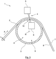
- Fig.3 shows a cross-sectional view of an embodiment of the arrangement 1 according to the invention for contactless thickness measurement of a material web 2, in particular a flexible, elastic and/or coated one.
- This has a cylindrical rolling body 3, which is sleeve-shaped and has a continuous cavity 9.
- the rolling body 3 has a circular cross-sectional area A and an axis of rotation R.
- a material web 2 is guided over an outer upper side of the cylindrical rolling body 3 in a direction of movement X, which is deflected by the cylindrical rolling body 3 and rolls on it without slipping.
- the arrangement 1 also comprises a sensor arrangement 4, which has a first sensor 5, which is directed towards a material web upper side 7, and which comprises a second sensor 6, which is directed towards a material web lower side 8.
- the sensors have detection devices, the detection direction of which is directed perpendicular to the material upper side or lower side.
- the detection areas of both sensors 5, 6 are exactly aligned with each other, so that the thickness t of the material web 2 is measured perpendicular to its main direction of propagation.
- the second sensor 6 is arranged in the cavity 9 of the cylindrical unwinding body 3 and is located between the outer circumference of the cylindrical unwinding device 3 and its axis of rotation R.
- the cylindrical unwinding body 3 has a plurality of openings 10 on its surface, each of which opens into the cavity 9.
- the openings 10 extend essentially tangentially along the surface of the Rolling body 3, so that when the cylindrical rolling body 3 rotates, the detection range of the sensor 6 detects the underside 8 of the material web through the opening 10 over the largest possible period of time or circumferential section of the cylindrical rolling body 3.
- the cylindrical rolling body 3 is therefore basically a sleeve with a sieve structure. This has a high degree of concentricity and can be manufactured galvanically.
- the great advantage of the device according to the invention is therefore that the material web 2 is supported by the cylindrical rolling body 3 in the detection range of both sensors 5, 6 and therefore no vibration can occur as with a freely floating material web.
- concentricity inaccuracies of the cylindrical rolling body 3 can be calculated out at any time, since the detection of the material web 2 on the top side 7 and on the bottom side 8 takes place simultaneously.
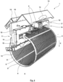
- Fig.4 shows a perspective view of an embodiment of the arrangement 1 according to the invention.
- the cylindrical rolling body 3 is designed in the form of a sleeve having a plurality of uniform openings 10.
- the sleeve 3 has an axis of rotation R and is supported on the front side by thin-ring bearings, which are not shown, however. It is intended that the sleeve 3 moves or rotates in a direction of movement X.
- no material web 2 is shown in the illustration.
- the openings 10 are designed such that 6 regularly spaced slots are distributed over the circumference of the sleeve 3, which are each spaced apart from one another by short material webs.
- the sleeve has a plurality of such openings 10 distributed over the circumference in the direction of axial propagation, which are each regularly spaced apart from one another on the sides.
- the openings 10 also run perpendicular to the axis of rotation R.
- the sleeve 3 encloses a cross-sectional area A and has a cavity 9.
- the sensor arrangement 4 is attached to a sensor carrier 17, which surrounds the sleeve 3 by means of carrier arms 18 over its edge areas in a U-shape such that the two first sensors 5 attached to the sensor carrier 17 and laterally spaced apart from one another are directed at an outer surface of the sleeve 3 and the two second sensors 6 opposite the first sensors 5 and laterally spaced apart from one another are directed at an inner surface of the sleeve 3.
- the first sensors 5 are each attached to an outer carrier arm 18 and the second sensors 6 are each attached to an inner carrier arm 18.
- the sensor carrier 17 is connected to the sleeve 3 via a linear guide 11. adjustable laterally transversely to the direction of movement X of the material web 2.
- Handles 14 are attached to both ends of the sensor carrier 17.
- Covers 15 are also hinged to the linear guide 11 via hinges 16, which can be folded down to darken the detection area during operation in order to increase the sensor accuracy.
- the covers 15 each have a handle 14 for operating the cover 15.
Landscapes
- Physics & Mathematics (AREA)
- General Physics & Mathematics (AREA)
- Length Measuring Devices With Unspecified Measuring Means (AREA)
- Measurement Of Length, Angles, Or The Like Using Electric Or Magnetic Means (AREA)
- Length Measuring Devices By Optical Means (AREA)
Claims (14)
- Arrangement (1) destiné à la mesure sans contact de l'épaisseur d'une bande continue (2) de matière en particulier flexible, élastique et/ou revêtue, comportant :un corps de contact (3) au moins en partie cylindrique ;une bande (2) de matière passée sur une surface du corps de contact (3) ;un arrangement (4) de capteurs destiné à la mesure de l'épaisseur (t) de bande de matière, dans lequel au moins un premier capteur (5) est dirigé vers une face supérieure (7) de bande de matière et au moins un second capteur (6) est dirigé vers une face inférieure (8) de bande de matière en faisant face au premier capteur (5) ;le second capteur (6) étant disposé au moins en partie au-dessous de la zone de contact entre la bande (2) de matière et le corps de contact (3),caractérisé en ce que le corps de contact cylindrique (3) comporte une cavité (9) dans laquelle est intégré le second capteur (6).
- Arrangement (1) selon la revendication 1, dans lequel le second capteur (6) est recouvert au moins en partie par une surface (A) de section transversale du corps de contact cylindrique (3) et disposé entre un axe de rotation (R) et la surface du corps de contact cylindrique (3).
- Arrangement (1) selon la revendication 1 ou 2, dans lequel la zone de détection du second capteur (6) comprend au moins en partie une face inférieure du corps de contact, en particulier une surface interne du corps de contact cylindrique (3).
- Arrangement (1) selon l'une quelconque des revendications précédentes, dans lequel le corps de contact cylindrique (3) est configuré en forme de manchon.
- Arrangement (1) selon l'une quelconque des revendications précédentes, dans lequel la surface du corps de contact (3) comporte au moins une perforation (10) se trouvant au moins en partie dans la zone de détection du second capteur (6).
- Arrangement (1) selon la revendication 5, dans lequel la perforation (10) s'étend essentiellement tangentiellement le long de la surface du corps de contact cylindrique (3).
- Arrangement (1) selon la revendication 5 ou 6, dans lequel la perforation (10) s'étend avec au moins une interruption autour de la circonférence totale du corps de contact cylindrique (3).
- Arrangement (1) selon l'une quelconque des revendications précédentes, dans lequel la surface du corps de contact cylindrique (3) comporte une pluralité de perforations (10) parallèlement espacées.
- Arrangement (1) selon l'une quelconque des revendications précédentes, dans lequel la surface du corps de contact cylindrique (3) présente une structure en tamis.
- Arrangement (1) selon l'une quelconque des revendications précédentes, dans lequel les capteurs (5,6) sont en disposition stationnaire par rapport à la direction de déplacement de la bande de matière (X).
- Arrangement (1) selon l'une quelconque des revendications précédentes, dans lequel les capteurs (5,6) sont fixés sur au moins un guide linéaire (11) réglable transversalement par rapport à la direction de déplacement de la bande de matière (X).
- Arrangement (1) selon l'une quelconque des revendications précédentes, dans lequel le corps de contact cylindrique (3) est placé au niveau de ses faces frontales par l'intermédiaire de minces paliers annulaires.
- Procédé pour la mesure sans contact de l'épaisseur d'une bande continue (2) de matière en particulier flexible, élastique et/ou revêtue, comportant les étapes :guidage d'une bande (2) de matière sur un corps de contact au moins en partie cylindrique (3) ;détermination simultanée d'une face supérieure (7) de bande de matière au moyen d'un premier capteur (5) et d'une face inférieure (8) de bande de matière au moyen d'un second capteur (6), les zones de détection des deux capteurs (5, 6) étant alignées l'une par rapport à l'autre, et le second capteur (6) étant disposé au moins en partie au-dessous de la zone de contact entre la bande (2) de matière et le corps de contact (3), le corps de contact cylindrique (3) comportant une cavité (9) dans laquelle est intégré le second capteur (6) ;détermination de l'épaisseur (t) de la bande de matière à l'aide des valeurs de capteurs déterminées du premier et du second capteur (5, 6).
- Procédé selon la revendication 13, dans lequel la bande (2) de matière est déviée par le corps de contact cylindrique (3).
Priority Applications (11)
| Application Number | Priority Date | Filing Date | Title |
|---|---|---|---|
| EP21198570.0A EP4155662B1 (fr) | 2021-09-23 | 2021-09-23 | Agencement de mesure de l'épaisseur d'une bande continue de matière |
| EP24192774.8A EP4459225B1 (fr) | 2021-09-23 | 2021-09-23 | Agencement de mesure de l'épaisseur d'une bande continue de matière |
| PCT/DE2022/100640 WO2023046228A1 (fr) | 2021-09-23 | 2022-08-26 | Assemblage pour mesurer l'épaisseur d'une bande continue de matériau |
| CN202280076845.1A CN118284785A (zh) | 2021-09-23 | 2022-08-26 | 用于测量连续材料幅材厚度的组件 |
| CA3232900A CA3232900A1 (fr) | 2021-09-23 | 2022-08-26 | Assemblage pour mesurer l'epaisseur d'une bande continue de materiau |
| KR1020247013200A KR20240109984A (ko) | 2021-09-23 | 2022-08-26 | 연속 재료 웹의 두께를 측정하기 위한 조립체 |
| US18/694,678 US20240384981A1 (en) | 2021-09-23 | 2022-08-26 | Assembly for Measuring the Thickness of a Continuous Material Web |
| JP2024519038A JP2024537763A (ja) | 2021-09-23 | 2022-08-26 | 連続的な材料ウェブの厚さを測定するための装置 |
| MX2024003668A MX2024003668A (es) | 2021-09-23 | 2022-08-26 | Disposicion para la medicion de espesor de una red de material continuo. |
| DE112022004522.1T DE112022004522A5 (de) | 2021-09-23 | 2022-08-26 | Anordnung zur dickenmessung einer kontinuierlichen materialbahn |
| TW111134542A TWI856367B (zh) | 2021-09-23 | 2022-09-13 | 用於對連續式材料幅面進行厚度測量的配置 |
Applications Claiming Priority (1)
| Application Number | Priority Date | Filing Date | Title |
|---|---|---|---|
| EP21198570.0A EP4155662B1 (fr) | 2021-09-23 | 2021-09-23 | Agencement de mesure de l'épaisseur d'une bande continue de matière |
Related Child Applications (2)
| Application Number | Title | Priority Date | Filing Date |
|---|---|---|---|
| EP24192774.8A Division EP4459225B1 (fr) | 2021-09-23 | 2021-09-23 | Agencement de mesure de l'épaisseur d'une bande continue de matière |
| EP24192774.8A Division-Into EP4459225B1 (fr) | 2021-09-23 | 2021-09-23 | Agencement de mesure de l'épaisseur d'une bande continue de matière |
Publications (3)
| Publication Number | Publication Date |
|---|---|
| EP4155662A1 EP4155662A1 (fr) | 2023-03-29 |
| EP4155662C0 EP4155662C0 (fr) | 2024-09-18 |
| EP4155662B1 true EP4155662B1 (fr) | 2024-09-18 |
Family
ID=77910719
Family Applications (2)
| Application Number | Title | Priority Date | Filing Date |
|---|---|---|---|
| EP21198570.0A Active EP4155662B1 (fr) | 2021-09-23 | 2021-09-23 | Agencement de mesure de l'épaisseur d'une bande continue de matière |
| EP24192774.8A Active EP4459225B1 (fr) | 2021-09-23 | 2021-09-23 | Agencement de mesure de l'épaisseur d'une bande continue de matière |
Family Applications After (1)
| Application Number | Title | Priority Date | Filing Date |
|---|---|---|---|
| EP24192774.8A Active EP4459225B1 (fr) | 2021-09-23 | 2021-09-23 | Agencement de mesure de l'épaisseur d'une bande continue de matière |
Country Status (10)
| Country | Link |
|---|---|
| US (1) | US20240384981A1 (fr) |
| EP (2) | EP4155662B1 (fr) |
| JP (1) | JP2024537763A (fr) |
| KR (1) | KR20240109984A (fr) |
| CN (1) | CN118284785A (fr) |
| CA (1) | CA3232900A1 (fr) |
| DE (1) | DE112022004522A5 (fr) |
| MX (1) | MX2024003668A (fr) |
| TW (1) | TWI856367B (fr) |
| WO (1) | WO2023046228A1 (fr) |
Family Cites Families (13)
| Publication number | Priority date | Publication date | Assignee | Title |
|---|---|---|---|---|
| DE3335766A1 (de) * | 1983-10-01 | 1985-04-11 | Leybold-Heraeus GmbH, 5000 Köln | Anordnung zur elektrischen messung von schichtdicken an laufenden baendern |
| DE4027709A1 (de) | 1990-08-31 | 1992-03-05 | Windmoeller & Hoelscher | Verfahren und vorrichtung zur ermittlung der dicke der von einer beschichtungsvorrichtung auf eine bahn aufgebrachten beschichtung |
| JPH08233541A (ja) * | 1995-02-23 | 1996-09-13 | Murata Mfg Co Ltd | シート厚み測定方法 |
| JPH09273912A (ja) * | 1996-04-04 | 1997-10-21 | Dainippon Printing Co Ltd | 厚み計測装置 |
| DE29607591U1 (de) * | 1996-04-27 | 1997-09-04 | Eduard Küsters Maschinenfabrik GmbH & Co. KG, 47805 Krefeld | Vorrichtung zur Flüssigkeitsbehandlung einer textilen Warenbahn |
| JP2009063522A (ja) * | 2007-09-07 | 2009-03-26 | Sony Corp | シート材料の厚み測定方法及び装置 |
| TW201205032A (en) * | 2010-07-22 | 2012-02-01 | New Power Team Technology Inc | Method for continuous measurement of plate thickness |
| CN102706286B (zh) * | 2012-06-25 | 2014-08-20 | 哈尔滨工业大学 | 板材板厚的激光测量装置 |
| KR101897835B1 (ko) * | 2012-07-24 | 2018-09-12 | 삼성에스디아이 주식회사 | 극판 두께 측정 장치 및 방법 |
| JP5280593B1 (ja) * | 2013-02-21 | 2013-09-04 | 株式会社日立パワーソリューションズ | ロールプレス設備およびそれに用いる厚み計 |
| US10240911B2 (en) * | 2017-06-12 | 2019-03-26 | Advanced Gauging Technologies, LLC | Laser gauge with full air gap measurement range |
| FR3077999B1 (fr) * | 2018-02-22 | 2020-03-20 | Commissariat A L'energie Atomique Et Aux Energies Alternatives | Rouleau de planeite, systeme de mesure de planeite et ligne d'operations de laminage associes |
| DE102019121959B4 (de) | 2019-08-14 | 2021-07-08 | Sml Maschinengesellschaft Mbh | Verfahren zur Herstellung einer Kunststoff-Folie |
-
2021
- 2021-09-23 EP EP21198570.0A patent/EP4155662B1/fr active Active
- 2021-09-23 EP EP24192774.8A patent/EP4459225B1/fr active Active
-
2022
- 2022-08-26 JP JP2024519038A patent/JP2024537763A/ja active Pending
- 2022-08-26 MX MX2024003668A patent/MX2024003668A/es unknown
- 2022-08-26 CN CN202280076845.1A patent/CN118284785A/zh active Pending
- 2022-08-26 KR KR1020247013200A patent/KR20240109984A/ko active Pending
- 2022-08-26 WO PCT/DE2022/100640 patent/WO2023046228A1/fr not_active Ceased
- 2022-08-26 CA CA3232900A patent/CA3232900A1/fr active Pending
- 2022-08-26 DE DE112022004522.1T patent/DE112022004522A5/de active Pending
- 2022-08-26 US US18/694,678 patent/US20240384981A1/en active Pending
- 2022-09-13 TW TW111134542A patent/TWI856367B/zh active
Also Published As
| Publication number | Publication date |
|---|---|
| DE112022004522A5 (de) | 2024-11-21 |
| EP4459225A3 (fr) | 2025-01-08 |
| EP4155662C0 (fr) | 2024-09-18 |
| EP4459225B1 (fr) | 2026-04-01 |
| KR20240109984A (ko) | 2024-07-12 |
| CN118284785A (zh) | 2024-07-02 |
| CA3232900A1 (fr) | 2023-03-30 |
| MX2024003668A (es) | 2024-08-14 |
| EP4155662A1 (fr) | 2023-03-29 |
| WO2023046228A1 (fr) | 2023-03-30 |
| TW202328634A (zh) | 2023-07-16 |
| TWI856367B (zh) | 2024-09-21 |
| JP2024537763A (ja) | 2024-10-16 |
| US20240384981A1 (en) | 2024-11-21 |
| EP4459225A2 (fr) | 2024-11-06 |
Similar Documents
| Publication | Publication Date | Title |
|---|---|---|
| EP3453501B1 (fr) | Dispositif coupe-joint | |
| EP2839951A1 (fr) | Dispositif de fabrication d'une bande de carton ondulé contrecollé au moins sur une face | |
| EP2048494B1 (fr) | Dispositif destiné à la détermination du format précis d'une bande de carton ondulé | |
| DE10321865B4 (de) | Messvorrichtung für ein längsbewegtes Band und Messverfahren für Prozessparameter einer Bandförderung | |
| EP4155662B1 (fr) | Agencement de mesure de l'épaisseur d'une bande continue de matière | |
| DE19541095C2 (de) | Verfahren zur Förderung eines Bandes aus plastischem Material und Fördertisch zur kontinuierlichen Förderung von bandförmigem plastischem Material | |
| EP0439830A2 (fr) | Dispositif de traitement d'une feuille continue | |
| EP3668809B1 (fr) | Bague à éléments d'écartement pour un rouleau d'écartement et rouleau d'écartement | |
| DE3812685C2 (de) | Verzögerungs-Vorrichtung für Bogenlagen | |
| WO2016177369A1 (fr) | Dispositif et procédé de mesure de la largeur et de l'épaisseur d'un objet plan | |
| WO1998023517A1 (fr) | Dispositif pour la repartition d'un flux de cahiers | |
| DE19906694C2 (de) | Breitstreckwalze | |
| DE19812524A1 (de) | Verfahren und Vorrichtung zum Positionieren von Wellrohrschläuchen | |
| EP3810345A1 (fr) | Dispositif et procédé pour le transport de matériau en bande, en particulier de feuillard à chaud | |
| EP1112952B1 (fr) | Dispositif pour plier en continu de matériau plat | |
| DE3231965A1 (de) | Vorrichtung zur messung des dickenprofils bandfoermigen materials | |
| DE19506463A1 (de) | Stauüberwachungseinrichtung für eine Transportvorrichtung für Papier, insbesondere für eine Papierbahn | |
| EP3420307B1 (fr) | Dispositif de mesure pour déterminer une longueur partielle d'un élément allongé en mouvement | |
| DE2951845C2 (de) | Vorrichtung zum Trocknen von band- und/oder blattförmigem, fotografischem Material | |
| DE19719063C2 (de) | Vorrichtung zur Herstellung eines Relining-Schlauchs | |
| EP0965684A2 (fr) | Dispositif d'application de materiau fluide ou pâteux sur un bande en mouvement | |
| EP4078082B1 (fr) | Dispositif de mesure pour mesurer la longueur de profilés d'étanchéité | |
| EP3788192B1 (fr) | Brise-balles à rail de guidage amélioré pour guider un bâti de machine | |
| EP0777013B1 (fr) | Machine pour la fabrication d'une bande continue | |
| DE19713207A1 (de) | Richtvorrichtung für Lagenmaterial, insbesondere Papier |
Legal Events
| Date | Code | Title | Description |
|---|---|---|---|
| PUAI | Public reference made under article 153(3) epc to a published international application that has entered the european phase |
Free format text: ORIGINAL CODE: 0009012 |
|
| STAA | Information on the status of an ep patent application or granted ep patent |
Free format text: STATUS: THE APPLICATION HAS BEEN PUBLISHED |
|
| AK | Designated contracting states |
Kind code of ref document: A1 Designated state(s): AL AT BE BG CH CY CZ DE DK EE ES FI FR GB GR HR HU IE IS IT LI LT LU LV MC MK MT NL NO PL PT RO RS SE SI SK SM TR |
|
| STAA | Information on the status of an ep patent application or granted ep patent |
Free format text: STATUS: REQUEST FOR EXAMINATION WAS MADE |
|
| 17P | Request for examination filed |
Effective date: 20230403 |
|
| RBV | Designated contracting states (corrected) |
Designated state(s): AL AT BE BG CH CY CZ DE DK EE ES FI FR GB GR HR HU IE IS IT LI LT LU LV MC MK MT NL NO PL PT RO RS SE SI SK SM TR |
|
| P01 | Opt-out of the competence of the unified patent court (upc) registered |
Effective date: 20230529 |
|
| GRAP | Despatch of communication of intention to grant a patent |
Free format text: ORIGINAL CODE: EPIDOSNIGR1 |
|
| STAA | Information on the status of an ep patent application or granted ep patent |
Free format text: STATUS: GRANT OF PATENT IS INTENDED |
|
| INTG | Intention to grant announced |
Effective date: 20240410 |
|
| GRAS | Grant fee paid |
Free format text: ORIGINAL CODE: EPIDOSNIGR3 |
|
| GRAA | (expected) grant |
Free format text: ORIGINAL CODE: 0009210 |
|
| STAA | Information on the status of an ep patent application or granted ep patent |
Free format text: STATUS: THE PATENT HAS BEEN GRANTED |
|
| AK | Designated contracting states |
Kind code of ref document: B1 Designated state(s): AL AT BE BG CH CY CZ DE DK EE ES FI FR GB GR HR HU IE IS IT LI LT LU LV MC MK MT NL NO PL PT RO RS SE SI SK SM TR |
|
| REG | Reference to a national code |
Ref country code: GB Ref legal event code: FG4D Free format text: NOT ENGLISH |
|
| REG | Reference to a national code |
Ref country code: CH Ref legal event code: EP |
|
| REG | Reference to a national code |
Ref country code: DE Ref legal event code: R096 Ref document number: 502021005170 Country of ref document: DE |
|
| REG | Reference to a national code |
Ref country code: IE Ref legal event code: FG4D Free format text: LANGUAGE OF EP DOCUMENT: GERMAN |
|
| U01 | Request for unitary effect filed |
Effective date: 20241016 |
|
| P04 | Withdrawal of opt-out of the competence of the unified patent court (upc) registered |
Free format text: CASE NUMBER: APP_58875/2024 Effective date: 20241028 |
|
| U07 | Unitary effect registered |
Designated state(s): AT BE BG DE DK EE FI FR IT LT LU LV MT NL PT RO SE SI Effective date: 20241031 |
|
| U20 | Renewal fee for the european patent with unitary effect paid |
Year of fee payment: 4 Effective date: 20241205 |
|
| PG25 | Lapsed in a contracting state [announced via postgrant information from national office to epo] |
Ref country code: NO Free format text: LAPSE BECAUSE OF FAILURE TO SUBMIT A TRANSLATION OF THE DESCRIPTION OR TO PAY THE FEE WITHIN THE PRESCRIBED TIME-LIMIT Effective date: 20241218 |
|
| PG25 | Lapsed in a contracting state [announced via postgrant information from national office to epo] |
Ref country code: GR Free format text: LAPSE BECAUSE OF FAILURE TO SUBMIT A TRANSLATION OF THE DESCRIPTION OR TO PAY THE FEE WITHIN THE PRESCRIBED TIME-LIMIT Effective date: 20241219 |
|
| PG25 | Lapsed in a contracting state [announced via postgrant information from national office to epo] |
Ref country code: HR Free format text: LAPSE BECAUSE OF FAILURE TO SUBMIT A TRANSLATION OF THE DESCRIPTION OR TO PAY THE FEE WITHIN THE PRESCRIBED TIME-LIMIT Effective date: 20240918 |
|
| PG25 | Lapsed in a contracting state [announced via postgrant information from national office to epo] |
Ref country code: RS Free format text: LAPSE BECAUSE OF FAILURE TO SUBMIT A TRANSLATION OF THE DESCRIPTION OR TO PAY THE FEE WITHIN THE PRESCRIBED TIME-LIMIT Effective date: 20241218 |
|
| PG25 | Lapsed in a contracting state [announced via postgrant information from national office to epo] |
Ref country code: RS Free format text: LAPSE BECAUSE OF FAILURE TO SUBMIT A TRANSLATION OF THE DESCRIPTION OR TO PAY THE FEE WITHIN THE PRESCRIBED TIME-LIMIT Effective date: 20241218 Ref country code: NO Free format text: LAPSE BECAUSE OF FAILURE TO SUBMIT A TRANSLATION OF THE DESCRIPTION OR TO PAY THE FEE WITHIN THE PRESCRIBED TIME-LIMIT Effective date: 20241218 Ref country code: HR Free format text: LAPSE BECAUSE OF FAILURE TO SUBMIT A TRANSLATION OF THE DESCRIPTION OR TO PAY THE FEE WITHIN THE PRESCRIBED TIME-LIMIT Effective date: 20240918 Ref country code: GR Free format text: LAPSE BECAUSE OF FAILURE TO SUBMIT A TRANSLATION OF THE DESCRIPTION OR TO PAY THE FEE WITHIN THE PRESCRIBED TIME-LIMIT Effective date: 20241219 |
|
| PG25 | Lapsed in a contracting state [announced via postgrant information from national office to epo] |
Ref country code: IS Free format text: LAPSE BECAUSE OF FAILURE TO SUBMIT A TRANSLATION OF THE DESCRIPTION OR TO PAY THE FEE WITHIN THE PRESCRIBED TIME-LIMIT Effective date: 20250118 |
|
| PG25 | Lapsed in a contracting state [announced via postgrant information from national office to epo] |
Ref country code: SM Free format text: LAPSE BECAUSE OF FAILURE TO SUBMIT A TRANSLATION OF THE DESCRIPTION OR TO PAY THE FEE WITHIN THE PRESCRIBED TIME-LIMIT Effective date: 20240918 |
|
| PG25 | Lapsed in a contracting state [announced via postgrant information from national office to epo] |
Ref country code: ES Free format text: LAPSE BECAUSE OF FAILURE TO SUBMIT A TRANSLATION OF THE DESCRIPTION OR TO PAY THE FEE WITHIN THE PRESCRIBED TIME-LIMIT Effective date: 20240918 |
|
| PG25 | Lapsed in a contracting state [announced via postgrant information from national office to epo] |
Ref country code: PL Free format text: LAPSE BECAUSE OF FAILURE TO SUBMIT A TRANSLATION OF THE DESCRIPTION OR TO PAY THE FEE WITHIN THE PRESCRIBED TIME-LIMIT Effective date: 20240918 Ref country code: CZ Free format text: LAPSE BECAUSE OF FAILURE TO SUBMIT A TRANSLATION OF THE DESCRIPTION OR TO PAY THE FEE WITHIN THE PRESCRIBED TIME-LIMIT Effective date: 20240918 |
|
| PG25 | Lapsed in a contracting state [announced via postgrant information from national office to epo] |
Ref country code: SK Free format text: LAPSE BECAUSE OF FAILURE TO SUBMIT A TRANSLATION OF THE DESCRIPTION OR TO PAY THE FEE WITHIN THE PRESCRIBED TIME-LIMIT Effective date: 20240918 |
|
| REG | Reference to a national code |
Ref country code: CH Ref legal event code: PL |
|
| PG25 | Lapsed in a contracting state [announced via postgrant information from national office to epo] |
Ref country code: MC Free format text: LAPSE BECAUSE OF FAILURE TO SUBMIT A TRANSLATION OF THE DESCRIPTION OR TO PAY THE FEE WITHIN THE PRESCRIBED TIME-LIMIT Effective date: 20240918 |
|
| PG25 | Lapsed in a contracting state [announced via postgrant information from national office to epo] |
Ref country code: CH Free format text: LAPSE BECAUSE OF NON-PAYMENT OF DUE FEES Effective date: 20240930 |
|
| PLBE | No opposition filed within time limit |
Free format text: ORIGINAL CODE: 0009261 |
|
| STAA | Information on the status of an ep patent application or granted ep patent |
Free format text: STATUS: NO OPPOSITION FILED WITHIN TIME LIMIT |
|
| 26N | No opposition filed |
Effective date: 20250619 |
|
| PGFP | Annual fee paid to national office [announced via postgrant information from national office to epo] |
Ref country code: IE Payment date: 20250904 Year of fee payment: 5 |
|
| U20 | Renewal fee for the european patent with unitary effect paid |
Year of fee payment: 5 Effective date: 20250916 |
|
| PG25 | Lapsed in a contracting state [announced via postgrant information from national office to epo] |
Ref country code: CY Free format text: LAPSE BECAUSE OF FAILURE TO SUBMIT A TRANSLATION OF THE DESCRIPTION OR TO PAY THE FEE WITHIN THE PRESCRIBED TIME-LIMIT; INVALID AB INITIO Effective date: 20210923 |
|
| PG25 | Lapsed in a contracting state [announced via postgrant information from national office to epo] |
Ref country code: HU Free format text: LAPSE BECAUSE OF FAILURE TO SUBMIT A TRANSLATION OF THE DESCRIPTION OR TO PAY THE FEE WITHIN THE PRESCRIBED TIME-LIMIT; INVALID AB INITIO Effective date: 20210923 |
|
| U1N | Appointed representative for the unitary patent procedure changed after the registration of the unitary effect |
Representative=s name: MARKS & CLERK LLP; GB |