EP4079476A1 - Tête de mortaiseuse, dispositif à mortaiser et machine de fabrication de boîte - Google Patents
Tête de mortaiseuse, dispositif à mortaiser et machine de fabrication de boîte Download PDFInfo
- Publication number
- EP4079476A1 EP4079476A1 EP21748015.1A EP21748015A EP4079476A1 EP 4079476 A1 EP4079476 A1 EP 4079476A1 EP 21748015 A EP21748015 A EP 21748015A EP 4079476 A1 EP4079476 A1 EP 4079476A1
- Authority
- EP
- European Patent Office
- Prior art keywords
- slotter
- slotter knife
- drive device
- knife base
- fixed
- Prior art date
- Legal status (The legal status is an assumption and is not a legal conclusion. Google has not performed a legal analysis and makes no representation as to the accuracy of the status listed.)
- Granted
Links
Images




Classifications
-
- B—PERFORMING OPERATIONS; TRANSPORTING
- B31—MAKING ARTICLES OF PAPER, CARDBOARD OR MATERIAL WORKED IN A MANNER ANALOGOUS TO PAPER; WORKING PAPER, CARDBOARD OR MATERIAL WORKED IN A MANNER ANALOGOUS TO PAPER
- B31B—MAKING CONTAINERS OF PAPER, CARDBOARD OR MATERIAL WORKED IN A MANNER ANALOGOUS TO PAPER
- B31B50/00—Making rigid or semi-rigid containers, e.g. boxes or cartons
- B31B50/02—Feeding or positioning sheets, blanks or webs
- B31B50/04—Feeding sheets or blanks
- B31B50/06—Feeding sheets or blanks from stacks
- B31B50/062—Feeding sheets or blanks from stacks from the underside of a magazine
-
- B—PERFORMING OPERATIONS; TRANSPORTING
- B26—HAND CUTTING TOOLS; CUTTING; SEVERING
- B26D—CUTTING; DETAILS COMMON TO MACHINES FOR PERFORATING, PUNCHING, CUTTING-OUT, STAMPING-OUT OR SEVERING
- B26D1/00—Cutting through work characterised by the nature or movement of the cutting member or particular materials not otherwise provided for; Apparatus or machines therefor; Cutting members therefor
- B26D1/01—Cutting through work characterised by the nature or movement of the cutting member or particular materials not otherwise provided for; Apparatus or machines therefor; Cutting members therefor involving a cutting member which does not travel with the work
- B26D1/12—Cutting through work characterised by the nature or movement of the cutting member or particular materials not otherwise provided for; Apparatus or machines therefor; Cutting members therefor involving a cutting member which does not travel with the work having a cutting member moving about an axis
- B26D1/25—Cutting through work characterised by the nature or movement of the cutting member or particular materials not otherwise provided for; Apparatus or machines therefor; Cutting members therefor involving a cutting member which does not travel with the work having a cutting member moving about an axis with a non-circular cutting member
- B26D1/26—Cutting through work characterised by the nature or movement of the cutting member or particular materials not otherwise provided for; Apparatus or machines therefor; Cutting members therefor involving a cutting member which does not travel with the work having a cutting member moving about an axis with a non-circular cutting member moving about an axis substantially perpendicular to the line of cut
- B26D1/28—Cutting through work characterised by the nature or movement of the cutting member or particular materials not otherwise provided for; Apparatus or machines therefor; Cutting members therefor involving a cutting member which does not travel with the work having a cutting member moving about an axis with a non-circular cutting member moving about an axis substantially perpendicular to the line of cut and rotating continuously in one direction during cutting
- B26D1/285—Cutting through work characterised by the nature or movement of the cutting member or particular materials not otherwise provided for; Apparatus or machines therefor; Cutting members therefor involving a cutting member which does not travel with the work having a cutting member moving about an axis with a non-circular cutting member moving about an axis substantially perpendicular to the line of cut and rotating continuously in one direction during cutting for thin material, e.g. for sheets, strips or the like
-
- B—PERFORMING OPERATIONS; TRANSPORTING
- B26—HAND CUTTING TOOLS; CUTTING; SEVERING
- B26D—CUTTING; DETAILS COMMON TO MACHINES FOR PERFORATING, PUNCHING, CUTTING-OUT, STAMPING-OUT OR SEVERING
- B26D3/00—Cutting work characterised by the nature of the cut made; Apparatus therefor
- B26D3/08—Making a superficial cut in the surface of the work without removal of material, e.g. scoring, incising
- B26D3/085—On sheet material
-
- B—PERFORMING OPERATIONS; TRANSPORTING
- B26—HAND CUTTING TOOLS; CUTTING; SEVERING
- B26D—CUTTING; DETAILS COMMON TO MACHINES FOR PERFORATING, PUNCHING, CUTTING-OUT, STAMPING-OUT OR SEVERING
- B26D5/00—Arrangements for operating and controlling machines or devices for cutting, cutting-out, stamping-out, punching, perforating, or severing by means other than cutting
-
- B—PERFORMING OPERATIONS; TRANSPORTING
- B26—HAND CUTTING TOOLS; CUTTING; SEVERING
- B26D—CUTTING; DETAILS COMMON TO MACHINES FOR PERFORATING, PUNCHING, CUTTING-OUT, STAMPING-OUT OR SEVERING
- B26D7/00—Details of apparatus for cutting, cutting-out, stamping-out, punching, perforating, or severing by means other than cutting
- B26D7/22—Safety devices specially adapted for cutting machines
-
- B—PERFORMING OPERATIONS; TRANSPORTING
- B26—HAND CUTTING TOOLS; CUTTING; SEVERING
- B26D—CUTTING; DETAILS COMMON TO MACHINES FOR PERFORATING, PUNCHING, CUTTING-OUT, STAMPING-OUT OR SEVERING
- B26D7/00—Details of apparatus for cutting, cutting-out, stamping-out, punching, perforating, or severing by means other than cutting
- B26D7/26—Means for mounting or adjusting the cutting member; Means for adjusting the stroke of the cutting member
- B26D7/2628—Means for adjusting the position of the cutting member
- B26D7/2642—Means for adjusting the position of the cutting member for slotting cutters
-
- B—PERFORMING OPERATIONS; TRANSPORTING
- B26—HAND CUTTING TOOLS; CUTTING; SEVERING
- B26F—PERFORATING; PUNCHING; CUTTING-OUT; STAMPING-OUT; SEVERING BY MEANS OTHER THAN CUTTING
- B26F1/00—Perforating; Punching; Cutting-out; Stamping-out; Apparatus therefor
- B26F1/38—Cutting-out; Stamping-out
- B26F1/384—Cutting-out; Stamping-out using rotating drums
-
- B—PERFORMING OPERATIONS; TRANSPORTING
- B31—MAKING ARTICLES OF PAPER, CARDBOARD OR MATERIAL WORKED IN A MANNER ANALOGOUS TO PAPER; WORKING PAPER, CARDBOARD OR MATERIAL WORKED IN A MANNER ANALOGOUS TO PAPER
- B31B—MAKING CONTAINERS OF PAPER, CARDBOARD OR MATERIAL WORKED IN A MANNER ANALOGOUS TO PAPER
- B31B50/00—Making rigid or semi-rigid containers, e.g. boxes or cartons
- B31B50/006—Controlling; Regulating; Measuring; Improving safety
-
- B—PERFORMING OPERATIONS; TRANSPORTING
- B31—MAKING ARTICLES OF PAPER, CARDBOARD OR MATERIAL WORKED IN A MANNER ANALOGOUS TO PAPER; WORKING PAPER, CARDBOARD OR MATERIAL WORKED IN A MANNER ANALOGOUS TO PAPER
- B31B—MAKING CONTAINERS OF PAPER, CARDBOARD OR MATERIAL WORKED IN A MANNER ANALOGOUS TO PAPER
- B31B50/00—Making rigid or semi-rigid containers, e.g. boxes or cartons
- B31B50/02—Feeding or positioning sheets, blanks or webs
- B31B50/04—Feeding sheets or blanks
-
- B—PERFORMING OPERATIONS; TRANSPORTING
- B31—MAKING ARTICLES OF PAPER, CARDBOARD OR MATERIAL WORKED IN A MANNER ANALOGOUS TO PAPER; WORKING PAPER, CARDBOARD OR MATERIAL WORKED IN A MANNER ANALOGOUS TO PAPER
- B31B—MAKING CONTAINERS OF PAPER, CARDBOARD OR MATERIAL WORKED IN A MANNER ANALOGOUS TO PAPER
- B31B50/00—Making rigid or semi-rigid containers, e.g. boxes or cartons
- B31B50/02—Feeding or positioning sheets, blanks or webs
- B31B50/04—Feeding sheets or blanks
- B31B50/042—Feeding sheets or blanks using rolls, belts or chains
-
- B—PERFORMING OPERATIONS; TRANSPORTING
- B31—MAKING ARTICLES OF PAPER, CARDBOARD OR MATERIAL WORKED IN A MANNER ANALOGOUS TO PAPER; WORKING PAPER, CARDBOARD OR MATERIAL WORKED IN A MANNER ANALOGOUS TO PAPER
- B31B—MAKING CONTAINERS OF PAPER, CARDBOARD OR MATERIAL WORKED IN A MANNER ANALOGOUS TO PAPER
- B31B50/00—Making rigid or semi-rigid containers, e.g. boxes or cartons
- B31B50/14—Cutting, e.g. perforating, punching, slitting or trimming
- B31B50/20—Cutting sheets or blanks
-
- B—PERFORMING OPERATIONS; TRANSPORTING
- B31—MAKING ARTICLES OF PAPER, CARDBOARD OR MATERIAL WORKED IN A MANNER ANALOGOUS TO PAPER; WORKING PAPER, CARDBOARD OR MATERIAL WORKED IN A MANNER ANALOGOUS TO PAPER
- B31B—MAKING CONTAINERS OF PAPER, CARDBOARD OR MATERIAL WORKED IN A MANNER ANALOGOUS TO PAPER
- B31B50/00—Making rigid or semi-rigid containers, e.g. boxes or cartons
- B31B50/26—Folding sheets, blanks or webs
-
- B—PERFORMING OPERATIONS; TRANSPORTING
- B31—MAKING ARTICLES OF PAPER, CARDBOARD OR MATERIAL WORKED IN A MANNER ANALOGOUS TO PAPER; WORKING PAPER, CARDBOARD OR MATERIAL WORKED IN A MANNER ANALOGOUS TO PAPER
- B31B—MAKING CONTAINERS OF PAPER, CARDBOARD OR MATERIAL WORKED IN A MANNER ANALOGOUS TO PAPER
- B31B50/00—Making rigid or semi-rigid containers, e.g. boxes or cartons
- B31B50/60—Uniting opposed surfaces or edges; Taping
-
- B—PERFORMING OPERATIONS; TRANSPORTING
- B31—MAKING ARTICLES OF PAPER, CARDBOARD OR MATERIAL WORKED IN A MANNER ANALOGOUS TO PAPER; WORKING PAPER, CARDBOARD OR MATERIAL WORKED IN A MANNER ANALOGOUS TO PAPER
- B31B—MAKING CONTAINERS OF PAPER, CARDBOARD OR MATERIAL WORKED IN A MANNER ANALOGOUS TO PAPER
- B31B2100/00—Rigid or semi-rigid containers made by folding single-piece sheets, blanks or webs
-
- B—PERFORMING OPERATIONS; TRANSPORTING
- B31—MAKING ARTICLES OF PAPER, CARDBOARD OR MATERIAL WORKED IN A MANNER ANALOGOUS TO PAPER; WORKING PAPER, CARDBOARD OR MATERIAL WORKED IN A MANNER ANALOGOUS TO PAPER
- B31B—MAKING CONTAINERS OF PAPER, CARDBOARD OR MATERIAL WORKED IN A MANNER ANALOGOUS TO PAPER
- B31B2100/00—Rigid or semi-rigid containers made by folding single-piece sheets, blanks or webs
- B31B2100/002—Rigid or semi-rigid containers made by folding single-piece sheets, blanks or webs characterised by the shape of the blank from which they are formed
- B31B2100/0022—Rigid or semi-rigid containers made by folding single-piece sheets, blanks or webs characterised by the shape of the blank from which they are formed made from tubular webs or blanks, including by tube or bottom forming operations
-
- B—PERFORMING OPERATIONS; TRANSPORTING
- B31—MAKING ARTICLES OF PAPER, CARDBOARD OR MATERIAL WORKED IN A MANNER ANALOGOUS TO PAPER; WORKING PAPER, CARDBOARD OR MATERIAL WORKED IN A MANNER ANALOGOUS TO PAPER
- B31B—MAKING CONTAINERS OF PAPER, CARDBOARD OR MATERIAL WORKED IN A MANNER ANALOGOUS TO PAPER
- B31B2110/00—Shape of rigid or semi-rigid containers
- B31B2110/30—Shape of rigid or semi-rigid containers having a polygonal cross section
- B31B2110/35—Shape of rigid or semi-rigid containers having a polygonal cross section rectangular, e.g. square
-
- B—PERFORMING OPERATIONS; TRANSPORTING
- B31—MAKING ARTICLES OF PAPER, CARDBOARD OR MATERIAL WORKED IN A MANNER ANALOGOUS TO PAPER; WORKING PAPER, CARDBOARD OR MATERIAL WORKED IN A MANNER ANALOGOUS TO PAPER
- B31B—MAKING CONTAINERS OF PAPER, CARDBOARD OR MATERIAL WORKED IN A MANNER ANALOGOUS TO PAPER
- B31B2120/00—Construction of rigid or semi-rigid containers
- B31B2120/30—Construction of rigid or semi-rigid containers collapsible; temporarily collapsed during manufacturing
- B31B2120/302—Construction of rigid or semi-rigid containers collapsible; temporarily collapsed during manufacturing collapsible into a flat condition
-
- B—PERFORMING OPERATIONS; TRANSPORTING
- B31—MAKING ARTICLES OF PAPER, CARDBOARD OR MATERIAL WORKED IN A MANNER ANALOGOUS TO PAPER; WORKING PAPER, CARDBOARD OR MATERIAL WORKED IN A MANNER ANALOGOUS TO PAPER
- B31B—MAKING CONTAINERS OF PAPER, CARDBOARD OR MATERIAL WORKED IN A MANNER ANALOGOUS TO PAPER
- B31B50/00—Making rigid or semi-rigid containers, e.g. boxes or cartons
- B31B50/14—Cutting, e.g. perforating, punching, slitting or trimming
- B31B50/20—Cutting sheets or blanks
- B31B50/22—Notching; Trimming edges of flaps
-
- B—PERFORMING OPERATIONS; TRANSPORTING
- B31—MAKING ARTICLES OF PAPER, CARDBOARD OR MATERIAL WORKED IN A MANNER ANALOGOUS TO PAPER; WORKING PAPER, CARDBOARD OR MATERIAL WORKED IN A MANNER ANALOGOUS TO PAPER
- B31B—MAKING CONTAINERS OF PAPER, CARDBOARD OR MATERIAL WORKED IN A MANNER ANALOGOUS TO PAPER
- B31B50/00—Making rigid or semi-rigid containers, e.g. boxes or cartons
- B31B50/25—Surface scoring
-
- B—PERFORMING OPERATIONS; TRANSPORTING
- B31—MAKING ARTICLES OF PAPER, CARDBOARD OR MATERIAL WORKED IN A MANNER ANALOGOUS TO PAPER; WORKING PAPER, CARDBOARD OR MATERIAL WORKED IN A MANNER ANALOGOUS TO PAPER
- B31B—MAKING CONTAINERS OF PAPER, CARDBOARD OR MATERIAL WORKED IN A MANNER ANALOGOUS TO PAPER
- B31B50/00—Making rigid or semi-rigid containers, e.g. boxes or cartons
- B31B50/26—Folding sheets, blanks or webs
- B31B50/36—Folding sheets, blanks or webs by continuously feeding the sheets, blanks or webs to stationary members, e.g. plates, ploughs or cores
-
- B—PERFORMING OPERATIONS; TRANSPORTING
- B31—MAKING ARTICLES OF PAPER, CARDBOARD OR MATERIAL WORKED IN A MANNER ANALOGOUS TO PAPER; WORKING PAPER, CARDBOARD OR MATERIAL WORKED IN A MANNER ANALOGOUS TO PAPER
- B31B—MAKING CONTAINERS OF PAPER, CARDBOARD OR MATERIAL WORKED IN A MANNER ANALOGOUS TO PAPER
- B31B50/00—Making rigid or semi-rigid containers, e.g. boxes or cartons
- B31B50/60—Uniting opposed surfaces or edges; Taping
- B31B50/62—Uniting opposed surfaces or edges; Taping by adhesives
- B31B50/624—Applying glue on blanks
-
- B—PERFORMING OPERATIONS; TRANSPORTING
- B31—MAKING ARTICLES OF PAPER, CARDBOARD OR MATERIAL WORKED IN A MANNER ANALOGOUS TO PAPER; WORKING PAPER, CARDBOARD OR MATERIAL WORKED IN A MANNER ANALOGOUS TO PAPER
- B31B—MAKING CONTAINERS OF PAPER, CARDBOARD OR MATERIAL WORKED IN A MANNER ANALOGOUS TO PAPER
- B31B50/00—Making rigid or semi-rigid containers, e.g. boxes or cartons
- B31B50/74—Auxiliary operations
- B31B50/81—Forming or attaching accessories, e.g. opening devices, closures or tear strings
- B31B50/86—Forming integral handles; Attaching separate handles
-
- B—PERFORMING OPERATIONS; TRANSPORTING
- B31—MAKING ARTICLES OF PAPER, CARDBOARD OR MATERIAL WORKED IN A MANNER ANALOGOUS TO PAPER; WORKING PAPER, CARDBOARD OR MATERIAL WORKED IN A MANNER ANALOGOUS TO PAPER
- B31B—MAKING CONTAINERS OF PAPER, CARDBOARD OR MATERIAL WORKED IN A MANNER ANALOGOUS TO PAPER
- B31B50/00—Making rigid or semi-rigid containers, e.g. boxes or cartons
- B31B50/74—Auxiliary operations
- B31B50/88—Printing; Embossing
-
- B—PERFORMING OPERATIONS; TRANSPORTING
- B31—MAKING ARTICLES OF PAPER, CARDBOARD OR MATERIAL WORKED IN A MANNER ANALOGOUS TO PAPER; WORKING PAPER, CARDBOARD OR MATERIAL WORKED IN A MANNER ANALOGOUS TO PAPER
- B31B—MAKING CONTAINERS OF PAPER, CARDBOARD OR MATERIAL WORKED IN A MANNER ANALOGOUS TO PAPER
- B31B50/00—Making rigid or semi-rigid containers, e.g. boxes or cartons
- B31B50/74—Auxiliary operations
- B31B50/92—Delivering
- B31B50/98—Delivering in stacks or bundles
Definitions
- a box making machine manufactures a box body (corrugated box) by processing a sheet material (for example, a corrugated cardboard box).
- the box making machine is configured of a sheet feeding section, a printing section, a slotter creaser section, a die cutting section, a folding section, a counter-ejector section, and the like.
- the sheet feeding section sends out the corrugated cardboard boxs stacked on a table one by one and sends them to the printing section at a constant speed.
- the printing section has a plurality of printing units and performs printing on the corrugated cardboard box.
- the upper slotter head has a disk-shaped fixed slotter knife base, a first cutting blade is fixed to the fixed slotter knife base, and a second cutting blade is movably mounted on the fixed slotter knife base in the circumferential direction.
- the fixed slotter knife base can be rotated by a first motor, and the second cutting blade can be moved in the circumferential direction by a second motor to adjust a relative position with the first cutting blade. Then, when the grooving process is performed on the sheet by the upper slotter head, the fixed slotter knife base is rotated by the first motor. At this time, it is necessary to maintain the relative positions of the first cutting blade and the second cutting blade.
- a slotter head of the present disclosure for achieving the above object includes a fixed slotter knife base that has a disk shape and is rotatably supported; a first cutting blade that is mounted on an outer peripheral portion of the fixed slotter knife base; a moving slotter knife base that is movably supported by the fixed slotter knife base in a circumferential direction; a second cutting blade that is mounted on an outer peripheral portion of the moving slotter knife base; a first drive device that rotationally drives the fixed slotter knife base; and a second drive device that rotationally drives the moving slotter knife base.
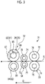
- the slotter creaser section 31 is subjected to a creasing line process and a groove cutting process on the corrugated cardboard box S.
- the slotter creaser section 31 has a slotter device 32.
- the slotter device 32 performs groove cutting process on the corrugated cardboard box S.
- the slotter creaser section 31 has a first creasing roll 33, a second creasing roll 34, a slitter head 35, and a slotter head 36.
- the corrugated cardboard box S is moved in the transfer direction D by the upper transfer belt 52 and the lower transfer belts 53 and 54.
- the gluing device 56 applies glue to the gluing margin strip 334, and the forming device 55 folds the corrugated cardboard box S downward with the creasing lines 322 and 324 as the base points.
- the folding force becomes stronger, and the end portions of the corrugated cardboard box S overlapping the gluing margin strip 334 and the gluing margin strip 334 are pressed and brought into close contact with each other, and both end portions of the corrugated cardboard box S are joined to become the corrugated box B.
- the corrugated box B is transferred to the counter-ejector section 61.
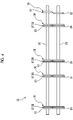
- the lower roll shaft 75 and the upper roll shaft 76 are vertically spaced parallel to each other at predetermined intervals, and are disposed along the horizontal direction orthogonal to the transfer direction D of the corrugated cardboard box S, and each end portion in the axial direction is rotatably supported by a frame (not shown).
- a plurality of creasing roll main bodies 71 are fixed to the lower roll shaft 75 at predetermined intervals in the axial direction.
- a plurality of receiving rolls 72 are fixed to the upper roll shaft 76 at predetermined intervals in the axial direction.
- the lower roll shaft 77 and the upper roll shaft 78 are disposed on the downstream side of the corrugated cardboard box S in the transfer direction D from the lower roll shaft 75 and the upper roll shaft 76.
- the slitter upper blade 81 and the slitter lower blade 82, and the upper slotter head 83 and the lower slotter head 84 are disposed so as to face each other vertically.
- the slitter head 35 and the slotter head 36 are disposed at the same positions as the first creasing roll 33 and the second creasing roll 34 in the horizontal direction orthogonal to the transfer direction D of the corrugated cardboard box S.
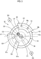
- the moving slotter knife base 102 is provided with an internal gear 102c on the inner peripheral portion of the disk plate portion 102a.
- the spline shaft (second rotary shaft) 131 is adjacent to the upper slotter shaft 85 with a predetermined gap, and is disposed parallel to the upper slotter shaft 85.
- the fixed slotter knife base 101 is formed with a through-hole 132 penetrating in the axial direction.
- the spline shaft 131 penetrates through the through-hole 132 of the fixed slotter knife base 101 with a gap.
- Disk-shaped support members 133 and 134 are fixed to each end portion of the upper slotter shaft 85 in the axial direction.
- Each end portion of the spline shaft 131 in the axial direction is rotatably supported by the support members 133 and 134 by bearings 135 and 136.
- the external gear 131a meshes with the internal gear 102c of the moving slotter knife base 102.
- the spline shaft 131, together with the upper slotter shaft 85 and the fixed slotter knife base 101, is rotatably (revolves) supported around the center O1 and rotatably (rotates) supported around the center O2.
- the rotational force of the drive gear 140 is transmitted to the spline shaft 131 via the geared hollow shaft 138 and the pinion gear 139.
- the moving slotter knife base 102 that meshes with the spline shaft 131 can be rotated.
- a torque limiter (overload protection device) 141 is provided between the second drive device 104 and the drive gear 140.
- the second drive device 104 is provided with a torque sensor (overload protection device) 142.
- control device 151 is connected to the operation device 153, and the command information output by the operator operating the operation device 153 is input.
- the command information includes the relative position information of the first slotter knife 87 and the second slotter knife 88 in the circumferential direction.
- the control device 151 may be configured to drive and control the first drive device 103 and the second drive device 104 based on the relative position information of the first slotter knife 87 and the second slotter knife 88 in the circumferential direction input from the operation device 153.
- Fig. 7 is a sectional view showing a cross section of the slotter head of a modified example.
- the moving slotter knife base 102A is provided with an external gear 102d on the outer peripheral portion.
- the second rotary shaft 161 is disposed parallel to the upper slotter shaft 85.
- the second rotary shaft 161 is rotatably supported by the frame 112 by the bearing 162.
- a pinion gear (external gear) 163 is fixed to the second rotary shaft 161, and the pinion gear 163 meshes with the external gear 102d of the moving slotter knife base 102A.
- the second rotary shaft 161 is rotatably supported around the center O2.
- Fig. 8 is a graph showing the rotation control of the slotter knife when the slotter device is started
- Fig. 9 is a graph showing the rotation control of the slotter knife when the slotter device is operated
- Fig. 10 is a graph showing the rotation control of the slotter knife when the slotter device is stopped.
- Fig. 11 is a schematic view showing a first stop state of the slotter device
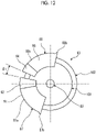
- Fig. 12 is a schematic view showing a second stop state of the slotter device
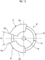
- Fig. 13 is a schematic view showing a third stop state of the slotter device.
- narrowing the interval between the first slotter knife 87 and the second slotter knife 88 means that the interval between the end portion of the tip 87b of the first slotter knife 87 and the end portion of the second slotter knife 88 on the tip 88b side is narrowed.
- widening the interval between the first slotter knife 87 and the second slotter knife 88 means the interval between the end portion of the tip 87b of the first slotter knife 87 and the end portion of the second slotter knife 88 on the tip 88b side is widened.
- the control device 151 rotates the first slotter knife 87 once by the first drive device 103 and rotates the second slotter knife 88 once by the second drive device 104 when the box making machine 10 (slotter creaser section 31) is operated, the rotation speed of the second slotter knife 88 by the second drive device 104 is reduced within a predetermined phase angle range.
- control method of the operating speed of the second slotter knife 88 by the second drive device 104 is not limited to the above-mentioned method. As shown by the two-dotted chain line in Figs. 5 and 9 , the operating speed of the second slotter knife 88 is lowered to v1 by the second drive device 104 in the range from the angle a1 to the angle a2 in which until the tip 88b comes into contact with and separates from the corrugated cardboard box S from the state where the second slotter knife 88 is maintained at a constant operating speed va by the second drive device 104.
- the first slotter knife 87 and the second slotter knife 88 may be configured of knife main bodies 91 and 93, and split knife bodies 92 and 94.
- the interval between the first slotter knife 87 and the second slotter knife 88 is widened so that the operation is stopped in a state where a predetermined gap (angle) ⁇ 1 is secured between the end portion of the first slotter knife 87 not on the tip 87b side and the end portion of the second slotter knife 88 not on the tip 88b side.
- the first slotter knife 87 and the second slotter knife 88 may move to predetermined positions and stop depending on the presence or absence of the split knife bodies 92 and 94 in the next grooving process.
- the slotter head includes the fixed slotter knife base 101 that has a disk shape and is rotatably supported, the first slotter knife (first cutting blade) 87 mounted on the outer peripheral portion of the fixed slotter knife base 101, the moving slotter knife base 102 that is movably supported by the fixed slotter knife base 101 in the circumferential direction, the second slotter knife (second cutting blade) 88 that is mounted on the outer peripheral portion of the moving slotter knife base 102, the first drive device 103 that rotationally drives the fixed slotter knife base 101, and the second drive device 104 that rotationally drives the moving slotter knife base 102.
- the relative positions of the first slotter knife 87 and the second slotter knife 88 are adjusted, so that after the rotation of the fixed slotter knife base 101 and the moving slotter knife base 102 is stopped, the first slotter knife 87 and the second slotter knife 88 can be stopped at a desired position, maintenance work and replacement work of the first slotter knife 87 and the second slotter knife 88 can be easily performed in a short time, and the work efficiency can be improved.
- the slotter head has the control device 151 that drives and controls the second drive device 104, the second slotter knife 88 has the slotter knife blade 88a having an arc shape and the tip 88b provided at the end portion of the slotter knife blade 88a in the circumferential direction, and the control device 151 adjusts the rotation speed of the moving slotter knife base 102 by the second drive device 104, so that at least the rotation speed when the tip 88b separates from the corrugated cardboard box S is lower than the rotation speed when the slotter knife blade 88a comes into contact with the corrugated cardboard box S.
- the slotter device includes the upper slotter shaft 85 and the lower slotter shaft 86 that are rotatably supported by the frame, and the upper slotter head 83 and the lower slotter head 84 which are fixed to the upper slotter shaft 85 and the lower slotter shaft 86, respectively to perform the groove cutting process of the corrugated cardboard box S. Therefore, since the drive system of the first slotter knife 87 and the drive system of the second slotter knife 88 are independent, in the upper slotter head 83, the gear mechanism for controlling the relative positions of the first slotter knife 87 and the second slotter knife 88 becomes unnecessary, and the slotter device can be simplified.
- the box making machine includes the sheet feeding section 11, the printing section 21, the slotter creaser section 31, the die cutting section 41, the folding section 51, and the counter-ejector section 61, and the slotter device 32 is provided in the slotter creaser section 31. Therefore, in the slotter creaser section 31, since the drive system of the first slotter knife 87 and the drive system of the second slotter knife 88 are independent, the upper slotter head 83 is not necessary to be provided with a gear mechanism for performing the relative position control between the first slotter knife 87 and the second slotter knife 88, and thereby the slotter device can be simplified.
Landscapes
- Life Sciences & Earth Sciences (AREA)
- Forests & Forestry (AREA)
- Engineering & Computer Science (AREA)
- Mechanical Engineering (AREA)
- Making Paper Articles (AREA)
Applications Claiming Priority (2)
| Application Number | Priority Date | Filing Date | Title |
|---|---|---|---|
| JP2020014668A JP7466320B2 (ja) | 2020-01-31 | 2020-01-31 | スロッタヘッドおよびスロッタ装置並びに製函機 |
| PCT/JP2021/001810 WO2021153371A1 (fr) | 2020-01-31 | 2021-01-20 | Tête de mortaiseuse, dispositif à mortaiser et machine de fabrication de boîte |
Publications (3)
| Publication Number | Publication Date |
|---|---|
| EP4079476A1 true EP4079476A1 (fr) | 2022-10-26 |
| EP4079476A4 EP4079476A4 (fr) | 2023-07-19 |
| EP4079476B1 EP4079476B1 (fr) | 2025-10-22 |
Family
ID=77079874
Family Applications (1)
| Application Number | Title | Priority Date | Filing Date |
|---|---|---|---|
| EP21748015.1A Active EP4079476B1 (fr) | 2020-01-31 | 2021-01-20 | Tête de rainurage, dispositif de rainurage et machine de fabrication de boîtes |
Country Status (5)
| Country | Link |
|---|---|
| US (1) | US20230075729A1 (fr) |
| EP (1) | EP4079476B1 (fr) |
| JP (1) | JP7466320B2 (fr) |
| CN (1) | CN115003478B (fr) |
| WO (1) | WO2021153371A1 (fr) |
Families Citing this family (4)
| Publication number | Priority date | Publication date | Assignee | Title |
|---|---|---|---|---|
| CN113733655B (zh) * | 2021-09-11 | 2023-07-25 | 温州捷华电子科技有限公司 | 一种鞋盒纸板开槽设备 |
| US12275563B2 (en) | 2023-04-06 | 2025-04-15 | Lancayle Heath Ham | Stackable container |
| CN116352448B (zh) * | 2023-06-02 | 2023-08-08 | 法兰克斯管道紧固件(常熟)有限公司 | 一种金属异型材生产用加工装置 |
| CN116511609B (zh) * | 2023-06-19 | 2023-09-01 | 江苏古彦铝业有限公司 | 一种铝合金门窗制造用切割机 |
Family Cites Families (15)
| Publication number | Priority date | Publication date | Assignee | Title |
|---|---|---|---|---|
| JPS51108986A (en) * | 1975-03-19 | 1976-09-27 | Ishikawa Seisakusho Kk | Danboorushiitono keesufukasajidochoseisochi |
| JPS6067118U (ja) | 1983-10-14 | 1985-05-13 | 株式会社 シンコ− | 鳴音兼用水浄化装置の鳴音間隔調整装置 |
| US5181899A (en) * | 1992-02-14 | 1993-01-26 | Lawrence Paper Company | Adjustable slotter wheel and sheet feeder retrofit apparatus for box blank making machines |
| JPH0939118A (ja) * | 1995-07-26 | 1997-02-10 | Isowa Corp | 段ボール製函機における溝切り装置 |
| JP3540498B2 (ja) * | 1996-03-26 | 2004-07-07 | 三菱重工業株式会社 | 段ボール製函機のフラップナイフ位置決め装置 |
| JP3861558B2 (ja) * | 2000-03-31 | 2006-12-20 | カシオ計算機株式会社 | 切断装置 |
| JP2004209837A (ja) * | 2002-12-26 | 2004-07-29 | Watanabe Denki:Kk | 段ボールシート枚葉印刷機及びスロッタの制御方法 |
| JP4754861B2 (ja) * | 2005-04-14 | 2011-08-24 | レンゴー株式会社 | 罫入れ溝切り装置 |
| JP2007136603A (ja) * | 2005-11-17 | 2007-06-07 | Shinko Kikai Seisakusho:Kk | 段ボールシートの糊代部切断加工装置 |
| JP6529778B2 (ja) * | 2015-02-17 | 2019-06-12 | 三菱重工機械システム株式会社 | スロッタ装置及びシートの溝切り加工方法、製函機 |
| JP6889983B2 (ja) * | 2015-12-24 | 2021-06-18 | 三菱重工機械システム株式会社 | スロッタ装置及びスロッタの位置決め方法、製函機 |
| US10821697B2 (en) * | 2016-12-27 | 2020-11-03 | Kabushiki Kaisha Isowa | Corrugated paperboard box making machine |
| JP6852874B2 (ja) * | 2016-12-27 | 2021-03-31 | 株式会社Isowa | 段ボールシート製函機 |
| JP7055724B2 (ja) * | 2018-09-14 | 2022-04-18 | 三菱重工機械システム株式会社 | スロッタ装置、及び、製函機 |
| FR3093466A1 (fr) * | 2019-03-08 | 2020-09-11 | Bobst Lyon | Unite de façonnage d’élément en plaque pour la fabrication de caisses pliantes |
-
2020
- 2020-01-31 JP JP2020014668A patent/JP7466320B2/ja active Active
-
2021
- 2021-01-20 CN CN202180009952.8A patent/CN115003478B/zh active Active
- 2021-01-20 US US17/795,944 patent/US20230075729A1/en active Pending
- 2021-01-20 WO PCT/JP2021/001810 patent/WO2021153371A1/fr not_active Ceased
- 2021-01-20 EP EP21748015.1A patent/EP4079476B1/fr active Active
Also Published As
| Publication number | Publication date |
|---|---|
| WO2021153371A1 (fr) | 2021-08-05 |
| CN115003478B (zh) | 2024-05-03 |
| EP4079476A4 (fr) | 2023-07-19 |
| JP7466320B2 (ja) | 2024-04-12 |
| EP4079476B1 (fr) | 2025-10-22 |
| CN115003478A (zh) | 2022-09-02 |
| JP2021121455A (ja) | 2021-08-26 |
| US20230075729A1 (en) | 2023-03-09 |
Similar Documents
| Publication | Publication Date | Title |
|---|---|---|
| EP4079476B1 (fr) | Tête de rainurage, dispositif de rainurage et machine de fabrication de boîtes | |
| US10800061B2 (en) | Slotter device, sheet slicing method, and carton former | |
| JP6889983B2 (ja) | スロッタ装置及びスロッタの位置決め方法、製函機 | |
| EP3450156B1 (fr) | Dispositif de pliage de feuille et machine de fabrication de boîte | |
| US4205596A (en) | Rotary die cutting device | |
| US11141947B2 (en) | Device for processing a plate element, processing unit and packaging production machine | |
| EP2230078B1 (fr) | Imprimante pour feuille de carton ondulé et machine à fabriquer des boîtes pour feuille de carton ondulé | |
| US20100101386A1 (en) | Variable signature length web cutting apparatus | |
| US5390599A (en) | On-line sheeter of printing system and method of changing length of cut | |
| US11602915B2 (en) | Sheet folding device and carton folder | |
| WO2013125349A1 (fr) | Machine à rainurer, procédé de rainurage de feuilles et dispositif de formation de cartons | |
| CN114144289B (zh) | 用于生产书封皮、盒盖或者游戏板的设备 | |
| JP7449719B2 (ja) | スリッタ装置、スリッタヘッドの位置決め方法および製函機 | |
| JP2003127251A (ja) | 段ボールシート製函機 | |
| CN223175450U (zh) | 一种折页机的断纸装置 | |
| JPH0445838Y2 (fr) |
Legal Events
| Date | Code | Title | Description |
|---|---|---|---|
| STAA | Information on the status of an ep patent application or granted ep patent |
Free format text: STATUS: THE INTERNATIONAL PUBLICATION HAS BEEN MADE |
|
| PUAI | Public reference made under article 153(3) epc to a published international application that has entered the european phase |
Free format text: ORIGINAL CODE: 0009012 |
|
| STAA | Information on the status of an ep patent application or granted ep patent |
Free format text: STATUS: REQUEST FOR EXAMINATION WAS MADE |
|
| 17P | Request for examination filed |
Effective date: 20220722 |
|
| AK | Designated contracting states |
Kind code of ref document: A1 Designated state(s): AL AT BE BG CH CY CZ DE DK EE ES FI FR GB GR HR HU IE IS IT LI LT LU LV MC MK MT NL NO PL PT RO RS SE SI SK SM TR |
|
| DAV | Request for validation of the european patent (deleted) | ||
| DAX | Request for extension of the european patent (deleted) | ||
| A4 | Supplementary search report drawn up and despatched |
Effective date: 20230615 |
|
| RIC1 | Information provided on ipc code assigned before grant |
Ipc: B26F 1/38 20060101ALI20230609BHEP Ipc: B26D 5/00 20060101ALI20230609BHEP Ipc: B31B 120/30 20170101ALI20230609BHEP Ipc: B31B 110/35 20170101ALI20230609BHEP Ipc: B31B 100/00 20170101ALI20230609BHEP Ipc: B26D 3/08 20060101ALI20230609BHEP Ipc: B31F 1/10 20060101ALI20230609BHEP Ipc: B31B 50/88 20170101ALI20230609BHEP Ipc: B31B 50/86 20170101ALI20230609BHEP Ipc: B31B 50/62 20170101ALI20230609BHEP Ipc: B31B 50/36 20170101ALI20230609BHEP Ipc: B31B 50/25 20170101ALI20230609BHEP Ipc: B31B 50/20 20170101ALI20230609BHEP Ipc: B31B 50/06 20170101ALI20230609BHEP Ipc: B31B 50/00 20170101ALI20230609BHEP Ipc: B26D 7/26 20060101ALI20230609BHEP Ipc: B31B 50/22 20170101ALI20230609BHEP Ipc: B26D 1/28 20060101AFI20230609BHEP |
|
| GRAP | Despatch of communication of intention to grant a patent |
Free format text: ORIGINAL CODE: EPIDOSNIGR1 |
|
| STAA | Information on the status of an ep patent application or granted ep patent |
Free format text: STATUS: GRANT OF PATENT IS INTENDED |
|
| INTG | Intention to grant announced |
Effective date: 20250516 |
|
| GRAS | Grant fee paid |
Free format text: ORIGINAL CODE: EPIDOSNIGR3 |
|
| GRAA | (expected) grant |
Free format text: ORIGINAL CODE: 0009210 |
|
| STAA | Information on the status of an ep patent application or granted ep patent |
Free format text: STATUS: THE PATENT HAS BEEN GRANTED |
|
| P01 | Opt-out of the competence of the unified patent court (upc) registered |
Free format text: CASE NUMBER: UPC_APP_3731_4079476/2025 Effective date: 20250820 |
|
| AK | Designated contracting states |
Kind code of ref document: B1 Designated state(s): AL AT BE BG CH CY CZ DE DK EE ES FI FR GB GR HR HU IE IS IT LI LT LU LV MC MK MT NL NO PL PT RO RS SE SI SK SM TR |
|
| REG | Reference to a national code |
Ref country code: CH Ref legal event code: F10 Free format text: ST27 STATUS EVENT CODE: U-0-0-F10-F00 (AS PROVIDED BY THE NATIONAL OFFICE) Effective date: 20251022 Ref country code: GB Ref legal event code: FG4D |
|
| REG | Reference to a national code |
Ref country code: DE Ref legal event code: R096 Ref document number: 602021040837 Country of ref document: DE |
|
| REG | Reference to a national code |
Ref country code: IE Ref legal event code: FG4D |
|
| REG | Reference to a national code |
Ref country code: SE Ref legal event code: TRGR |
|
| PGFP | Annual fee paid to national office [announced via postgrant information from national office to epo] |
Ref country code: SE Payment date: 20251216 Year of fee payment: 6 |
|
| REG | Reference to a national code |
Ref country code: NL Ref legal event code: MP Effective date: 20251022 |
|
| PG25 | Lapsed in a contracting state [announced via postgrant information from national office to epo] |
Ref country code: NL Free format text: LAPSE BECAUSE OF FAILURE TO SUBMIT A TRANSLATION OF THE DESCRIPTION OR TO PAY THE FEE WITHIN THE PRESCRIBED TIME-LIMIT Effective date: 20251022 |
|
| PG25 | Lapsed in a contracting state [announced via postgrant information from national office to epo] |
Ref country code: ES Free format text: LAPSE BECAUSE OF FAILURE TO SUBMIT A TRANSLATION OF THE DESCRIPTION OR TO PAY THE FEE WITHIN THE PRESCRIBED TIME-LIMIT Effective date: 20251022 |
|
| REG | Reference to a national code |
Ref country code: LT Ref legal event code: MG9D |
|
| PG25 | Lapsed in a contracting state [announced via postgrant information from national office to epo] |
Ref country code: NO Free format text: LAPSE BECAUSE OF FAILURE TO SUBMIT A TRANSLATION OF THE DESCRIPTION OR TO PAY THE FEE WITHIN THE PRESCRIBED TIME-LIMIT Effective date: 20260122 |
|
| PG25 | Lapsed in a contracting state [announced via postgrant information from national office to epo] |
Ref country code: FI Free format text: LAPSE BECAUSE OF FAILURE TO SUBMIT A TRANSLATION OF THE DESCRIPTION OR TO PAY THE FEE WITHIN THE PRESCRIBED TIME-LIMIT Effective date: 20251022 Ref country code: AT Free format text: LAPSE BECAUSE OF FAILURE TO SUBMIT A TRANSLATION OF THE DESCRIPTION OR TO PAY THE FEE WITHIN THE PRESCRIBED TIME-LIMIT Effective date: 20251022 Ref country code: HR Free format text: LAPSE BECAUSE OF FAILURE TO SUBMIT A TRANSLATION OF THE DESCRIPTION OR TO PAY THE FEE WITHIN THE PRESCRIBED TIME-LIMIT Effective date: 20251022 |
|
| REG | Reference to a national code |
Ref country code: AT Ref legal event code: MK05 Ref document number: 1848775 Country of ref document: AT Kind code of ref document: T Effective date: 20251022 |
|
| PG25 | Lapsed in a contracting state [announced via postgrant information from national office to epo] |
Ref country code: RS Free format text: LAPSE BECAUSE OF FAILURE TO SUBMIT A TRANSLATION OF THE DESCRIPTION OR TO PAY THE FEE WITHIN THE PRESCRIBED TIME-LIMIT Effective date: 20260122 |
|
| PG25 | Lapsed in a contracting state [announced via postgrant information from national office to epo] |
Ref country code: IS Free format text: LAPSE BECAUSE OF FAILURE TO SUBMIT A TRANSLATION OF THE DESCRIPTION OR TO PAY THE FEE WITHIN THE PRESCRIBED TIME-LIMIT Effective date: 20260222 |
|
| PGFP | Annual fee paid to national office [announced via postgrant information from national office to epo] |
Ref country code: FR Payment date: 20260122 Year of fee payment: 6 |
|
| PG25 | Lapsed in a contracting state [announced via postgrant information from national office to epo] |
Ref country code: PT Free format text: LAPSE BECAUSE OF FAILURE TO SUBMIT A TRANSLATION OF THE DESCRIPTION OR TO PAY THE FEE WITHIN THE PRESCRIBED TIME-LIMIT Effective date: 20260223 |
|
| PG25 | Lapsed in a contracting state [announced via postgrant information from national office to epo] |
Ref country code: PL Free format text: LAPSE BECAUSE OF FAILURE TO SUBMIT A TRANSLATION OF THE DESCRIPTION OR TO PAY THE FEE WITHIN THE PRESCRIBED TIME-LIMIT Effective date: 20251022 |
|
| PG25 | Lapsed in a contracting state [announced via postgrant information from national office to epo] |
Ref country code: LV Free format text: LAPSE BECAUSE OF FAILURE TO SUBMIT A TRANSLATION OF THE DESCRIPTION OR TO PAY THE FEE WITHIN THE PRESCRIBED TIME-LIMIT Effective date: 20251022 |