EP4079647B1 - Vorrichtung und verfahren zum transportieren von fertig zugeschnittenen und befüllten schlauchstücken - Google Patents
Vorrichtung und verfahren zum transportieren von fertig zugeschnittenen und befüllten schlauchstücken Download PDFInfo
- Publication number
- EP4079647B1 EP4079647B1 EP21170188.3A EP21170188A EP4079647B1 EP 4079647 B1 EP4079647 B1 EP 4079647B1 EP 21170188 A EP21170188 A EP 21170188A EP 4079647 B1 EP4079647 B1 EP 4079647B1
- Authority
- EP
- European Patent Office
- Prior art keywords
- thread
- opening
- bag
- transport wheel
- station
- Prior art date
- Legal status (The legal status is an assumption and is not a legal conclusion. Google has not performed a legal analysis and makes no representation as to the accuracy of the status listed.)
- Active
Links
Images





Classifications
-
- B—PERFORMING OPERATIONS; TRANSPORTING
- B65—CONVEYING; PACKING; STORING; HANDLING THIN OR FILAMENTARY MATERIAL
- B65C—LABELLING OR TAGGING MACHINES, APPARATUS, OR PROCESSES
- B65C9/00—Details of labelling machines or apparatus
- B65C9/08—Label feeding
- B65C9/18—Label feeding from strips, e.g. from rolls
-
- B—PERFORMING OPERATIONS; TRANSPORTING
- B65—CONVEYING; PACKING; STORING; HANDLING THIN OR FILAMENTARY MATERIAL
- B65B—MACHINES, APPARATUS OR DEVICES FOR, OR METHODS OF, PACKAGING ARTICLES OR MATERIALS; UNPACKING
- B65B29/00—Packaging of materials presenting special problems
- B65B29/02—Packaging of substances, e.g. tea, which are intended to be infused in the package
- B65B29/04—Attaching, or forming and attaching, string handles or tags to tea bags
-
- B—PERFORMING OPERATIONS; TRANSPORTING
- B65—CONVEYING; PACKING; STORING; HANDLING THIN OR FILAMENTARY MATERIAL
- B65B—MACHINES, APPARATUS OR DEVICES FOR, OR METHODS OF, PACKAGING ARTICLES OR MATERIALS; UNPACKING
- B65B29/00—Packaging of materials presenting special problems
- B65B29/02—Packaging of substances, e.g. tea, which are intended to be infused in the package
- B65B29/028—Packaging of substances, e.g. tea, which are intended to be infused in the package packaging infusion material into filter bags
-
- B—PERFORMING OPERATIONS; TRANSPORTING
- B65—CONVEYING; PACKING; STORING; HANDLING THIN OR FILAMENTARY MATERIAL
- B65B—MACHINES, APPARATUS OR DEVICES FOR, OR METHODS OF, PACKAGING ARTICLES OR MATERIALS; UNPACKING
- B65B41/00—Supplying or feeding container-forming sheets or wrapping material
- B65B41/02—Feeding sheets or wrapper blanks
- B65B41/04—Feeding sheets or wrapper blanks by grippers
- B65B41/06—Feeding sheets or wrapper blanks by grippers by suction-operated grippers
-
- B—PERFORMING OPERATIONS; TRANSPORTING
- B65—CONVEYING; PACKING; STORING; HANDLING THIN OR FILAMENTARY MATERIAL
- B65B—MACHINES, APPARATUS OR DEVICES FOR, OR METHODS OF, PACKAGING ARTICLES OR MATERIALS; UNPACKING
- B65B43/00—Forming, feeding, opening or setting-up containers or receptacles in association with packaging
- B65B43/42—Feeding or positioning bags, boxes, or cartons in the distended, opened, or set-up state; Feeding preformed rigid containers, e.g. tins, capsules, glass tubes, glasses, to the packaging position; Locating containers or receptacles at the filling position; Supporting containers or receptacles during the filling operation
- B65B43/54—Means for supporting containers or receptacles during the filling operation
- B65B43/60—Means for supporting containers or receptacles during the filling operation rotatable
-
- B—PERFORMING OPERATIONS; TRANSPORTING
- B65—CONVEYING; PACKING; STORING; HANDLING THIN OR FILAMENTARY MATERIAL
- B65B—MACHINES, APPARATUS OR DEVICES FOR, OR METHODS OF, PACKAGING ARTICLES OR MATERIALS; UNPACKING
- B65B61/00—Auxiliary devices, not otherwise provided for, for operating on sheets, blanks, webs, binding material, containers or packages
- B65B61/26—Auxiliary devices, not otherwise provided for, for operating on sheets, blanks, webs, binding material, containers or packages for marking or coding completed packages
-
- B—PERFORMING OPERATIONS; TRANSPORTING
- B65—CONVEYING; PACKING; STORING; HANDLING THIN OR FILAMENTARY MATERIAL
- B65B—MACHINES, APPARATUS OR DEVICES FOR, OR METHODS OF, PACKAGING ARTICLES OR MATERIALS; UNPACKING
- B65B63/00—Auxiliary devices, not otherwise provided for, for operating on articles or materials to be packaged
- B65B63/005—Auxiliary devices, not otherwise provided for, for operating on articles or materials to be packaged for marking or coding articles prior to packaging
-
- B—PERFORMING OPERATIONS; TRANSPORTING
- B65—CONVEYING; PACKING; STORING; HANDLING THIN OR FILAMENTARY MATERIAL
- B65C—LABELLING OR TAGGING MACHINES, APPARATUS, OR PROCESSES
- B65C9/00—Details of labelling machines or apparatus
- B65C9/02—Devices for moving articles, e.g. containers, past labelling station
Definitions
- the present invention relates to a device and a method for transporting pre-cut and filled hose pieces within a machine for producing bags filled with brewable material.
- EP 3 733 384 A1 This device has a transport wheel that has several bag holders distributed around its circumference.
- the cut and filled piece of tubing is inserted radially into the transport wheel to form a bag from the piece of tubing.
- the piece of tubing is shaped in such a way that a chamber of a bag is created that extends radially in relation to the transport wheel, with the bottom of the bag being radially inward and the head of the bag being radially outward.
- This station is also referred to as an insertion station in the description of the present invention.
- the cut and filled piece of tubing can also be designed as a single or double chamber bag in the context of the invention.
- the initially flat cut is shaped in such a way that the chamber and thus the shape of the bag is essentially predetermined.
- the head is exposed in the area of the outer circumference of the transport wheel. In subsequent processing steps and while the transport wheel is rotating, a label is fed to the head of the bag according to the prior art and connected to the head of the bag.
- the bag is then wrapped in a length of wrapping.
- This wrapping is basically placed in a U-shape around the bag.
- the opposing edges of the wrapping are then welded to seal the bag completely in the wrapping.
- the wrapping is made of a film through which the bag is packed aroma-tight within the wrapping.
- EP 2 681 119 B1 The bag is first removed from the transport wheel in a radial direction and then inserted radially into the transport wheel with the bottom facing forward, whereby the cover is wrapped around the bag.
- the bag is pivoted in the transport wheel so that when the bag is removed from the transport wheel, the bag is removed from the transport wheel with the bottom facing forward and is wrapped in the wrapping.
- Handling the thread within the transport wheel is not entirely unproblematic.
- the transport wheel must rotate at a relatively high speed to ensure high productivity.
- the transport wheel has a large number of clamps, edges, joints and the like on which the thread can get caught.
- the present invention is based on the problem of specifying a device and a method of the type mentioned at the beginning, in which the thread is handled with greater safety in the area of the transport wheel.
- the present invention proposes a device having the feature of claim 1.
- This device has a transport wheel in a manner known per se, which has several holders distributed around its circumference, each of which holds the bag.
- An insertion station is assigned to the transport wheel, in which one of the tube pieces is inserted into the holder in a radial direction to form a bag with at least one chamber.
- the chamber extends between a head and a bottom of the bag.
- the bottom of the bag is normally located radially inwards.
- the head of the bag is already in the insertion station, preferably in the area of the outer circumference of the transport wheel.
- a label feed station is also provided, in which a label is fed to the head.
- a connection station is implemented, in which a thread is connected to the label and/or the bag.
- a removal station is provided in a manner known per se, in which the bag is removed from the transport wheel.
- the previously mentioned stations are usually provided distributed in the circumferential direction around the transport wheel.
- the label feeding station and the connecting station can be provided at a uniform position between the insertion station and the removal station.
- the bag is acted upon at the respective stations in order to achieve the respective performance result at the respective station.
- the bag can be guided continuously or intermittently past the respective stations and/or away from or towards the respective station by rotating the transport wheel.
- each holder is assigned a thread channel that can be connected to a negative pressure source and a positive pressure source.
- the thread channel is designed to accommodate a thread. This is usually a piece of thread.
- the thread is placed in the thread channel, it is usually already connected to the bag, i.e. to the piece of hose that surrounds the bag. Accordingly, the piece of hose is already inserted into the transport wheel in the insertion station with the thread attached to it.
- the thread is temporarily accommodated in the thread channel before the label and/or bag are connected to the thread and during the rotation of the transport wheel.
- a negative pressure threshold usually acts, through which the thread is not only sucked into the thread channel, but also the rotation of the transport wheel is held within the thread channel. Only when the thread is connected to the label and/or the bag is the thread blown out of the thread channel so that it is available outside the thread channel for attachment to the label and/or the bag.
- the thread channel has a thread opening for introducing the thread.
- This is preferably located adjacent to a receptacle for the actual bag in the form of a holding shaft, for example.
- the thread channel also has an air guide opening, which can be brought into operative connection with a negative pressure opening or a positive pressure opening due to the rotation of the transport wheel.
- the thread channel then usually has only two openings. The thread is introduced into the thread opening. The pressure level acting in the thread channel is conveyed through the air guide opening.
- the operative connection between the air guide opening and a vacuum opening, which is usually provided at a fixed location, and an overpressure opening, which is also usually provided at a fixed location, is established by the rotation of the transport wheel.
- the desired pressure level in the thread channel can be set by rotating the transport wheel alone. No complex valves or the like are then necessary.
- the vacuum opening can constantly have a vacuum. The same applies to the overpressure at the overpressure opening.
- the desired pressures are inevitably set in the thread channel simply by moving the air guide opening past the vacuum opening or the overpressure opening. This creates directed flows in the thread channel through which the thread is laid, conveyed or held.
- the air guide opening is preferably recessed on a surface of the holder that extends radially in relation to the axis of rotation of the transport wheel.
- the vacuum opening or the overpressure opening that is operatively connected to the air guide opening is provided opposite the air guide opening.
- the vacuum opening and the overpressure opening are thus usually provided in a common plane and are exposed there, which extends parallel to the radial plane of the transport wheel.
- the negative pressure opening is designed as an elongated open channel, usually as a ring segment.
- the air guide opening is preferably in operative connection with the negative pressure opening as the transport wheel rotates from the insertion station to the connection station.
- the thread is effectively sucked into the thread channel via the negative pressure during the rotation of the transport wheel and is held there.
- the Treatment and processing of the thread on the transport wheel The desired pressure conditions in the thread channel are set solely by the rotation of the transport wheel in the holding channel by bringing its vacuum opening into operative connection with the vacuum opening and/or the overpressure opening depending on the angular position of the transport wheel or arranging it so that no working pressure is set in the thread channel. This is superfluous, for example, after the thread is connected to the bag and the label or is fixed to the transport wheel opposite the bag. The same applies to angular positions of the transport wheel in which the holder is prepared, for example, to receive another bag after it has been delivered to the removal station.
- connection station has a thread guide that can be arranged opposite the thread opening of the thread channel with the label in between.
- This thread guide takes up the thread blown out of the thread channel and redirects it.
- the overpressure acting can redirect the thread several times and blow it through the plane containing the label, so that the thread is guided past the label and/or through recesses within the label and is thus knotted with the label.
- At least the section of the thread channel having the thread opening is provided to be movable in order to be brought closer to the head of the bag in the connection station after the bag has been inserted into the receptacle for attaching the thread to the label.
- This design allows the label to be connected to the bag in greater proximity to it and, as a result or in a subsequent station, to be attached to the bag in such a way that the thread and the label can be handled as a unit at least until they are wrapped in the wrapping when the bag, thread and label are removed.
- a section of the thread channel that forms the thread opening can be arranged pivotably on the holder for this purpose.
- the transport wheel has a hole for each holder.
- an axle body carrying the holder is pivotably mounted about a pivot axis.
- a guide is provided which gives the holder an orientation in relation to the pivot axis during the rotation of the transport wheel.
- the guide ensures that an air guide opening of the thread channel, which is arranged eccentrically to the pivot axis, is operatively connected to the vacuum opening in the insertion station and to the overpressure opening in the connection station.
- the orientation of the holder in relation to the pivot axis in the insertion station and in the connection station can remain the same.
- the vacuum opening can also have a different radial distance from the axis of rotation of the transport wheel than the overpressure opening, so that by pivoting the holder about the pivot axis, the air guide opening can be operatively connected to the vacuum opening or the overpressure opening.
- the axle body preferably has at least one guide arm extending transversely to the pivot axis of the axle body, the free end of which is provided in a guide.
- the guide arm usually has a guide pin which is guided in a guide groove which is recessed in a disk which is provided on the side of the transport wheel opposite the holder. This guide disk forms the negative pressure opening or the positive pressure opening or carries means for forming the corresponding openings.
- the present invention proposes a holder for holding a bag filled with brewable material.
- This holder has a thread channel that can be connected to a pressure source.
- the holder has a first opening, usually provided adjacent to a holder for the bag, for introducing the thread connected at least to the label or the bag, and a second air guide opening connected to this first opening via the thread channel, which can be fluidically connected to the pressure source.
- the air guide opening can be connected to the pressure source in such a way that the pressure source influences the internal pressure in the thread channel to such an extent that a flow of the ambient air of the holder is generated in the thread channel, through which the thread is sucked into the thread channel or blown out of it.
- This holder preferably has an axle body that is pivotably mounted about a pivot axis.
- This pivot axis is usually also the extension axis of the thread channel.
- the holder accordingly usually has an elongated axle body about which the holder for the bag, which can be formed by a holding shaft, for example, can be pivoted in order to pivot an end of the bag that is usually at the head end and thus align it at the head end so that the thread and/or the label can be connected to the bag in the desired orientation of the bag.
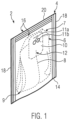
- the Figure 1 shows an embodiment of a packaging unit identified by reference numeral 2, consisting of a cover 4, in which a bag 6 with a thread 8 attached to a head 7 of the bag 6 and a label arranged on the head 7 and thus opposite a bottom 9 of the bag 6 designed as a double-chamber bag 10.
- the thread 8 is knotted on the one hand to the label 10 and on the other hand is passed through a slot 12 of the label 10 and is accordingly secured to the label 10.
- the contents of the wrapping are produced in this way on the transport wheel described below.
- the wrapping 4 consists of a length of aroma-tight film which is folded over a fold 14 to form two adjacent legs 16 and is sealed via two parallel longitudinal weld seams 18 and a transverse weld seam 20.
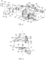
- the transport wheel 100 has a Figures 3 to 7 detailed holder 104, which comprises a receptacle in the form of a holding shaft 106 receiving the bag 6, to which a bag clamp 108 is assigned, which fixes the bag 6 in the holder 104.
- the holding shaft 106 in the insertion station 102 is aligned strictly radially, so that the bag 6 can be inserted into the holding shaft 106 by radially stuffing it into the holder 104.
- FIG 2 an arcuate insertion segment 110 can be seen, which is moved alternately in order to insert a piece of tubing into the respective holder 104 during the formation of the bag 6, forming at least one chamber of the bag.
- the rotation of the transport wheel 100 is interrupted in each case. Accordingly, the transport wheel 100 is driven to rotate cyclically during the further processing of the bag 6, with the transport wheel 100 standing still during the respective processing steps.
- a label feed station 112 Adjacent to the insertion station 102 in the transport direction T is a label feed station 112 in which a cut label 10 provided with a slot and holes for the thread 8 to pass through is fed to the head 7 of the bag 6.
- the holder 104 has a radial orientation that is unchanged compared to the orientation in the insertion station 102.
- the holder 104 is pivoted so that this holder 104 is in the thread securing station marked with reference number 116 116 is pivoted by 90° and accordingly extends tangentially relative to a rotation axis D of the transport wheel 100.
- this thread securing station 116 the thread 8 is inserted into the slot 12 of the label 10.
- the thread 8 is thus assigned to the label 10 and then to the bag 6 in order to prevent the thread from penetrating the sealing of the edges of the wrapping material during the subsequent wrapping of the bag or even getting caught on parts of the device during further handling of the bag 4 together with the label 10 and the thread 8.
- a removal station is identified by reference number 118.
- the bag 6 is rotated by 180° compared to its orientation in the insertion station 102. While the bag 6 is inserted into the holder 104 with its base 9 facing forwards in the insertion station 102, when the bag 6 is pushed out radially in the removal station 118, the bag 6 is pushed out with the base 9 facing forwards.
- pivoting station 120 in which the holder 104 is pivoted by 180° so that it is appropriately aligned for receiving a new bag 6 in the insertion station 102.
- the bag 6 is gripped in the removal station by a bag handling device 122 in the holder 104 and pulled radially out of the holder 104.
- the bag handling device 122 has leading and trailing arms 124 for this purpose, which clamp the bag in the area of the base 9 and pull it radially out of the holder 104 (cf. Figure 2 ).
- These arms 124 are preceded by Figure 2 shown leading and trailing arms 126 of a wrapping material handling device 128, which grip the wrapping material guided tangentially past the transport wheel 100 via a wrapping material guide 130 to form the fold 14 and convey it out radially (cf. Figure 2 ).
- a sealing transport wheel 132 of a sealing station which receives the wrapping 4 together with the bag 6, the thread 8 and the label 10, wherein the material of the wrapping 4 is already provided with the fold 14 and the transverse edge opposite the fold 14 and the two longitudinal edges are welded by a welding device which is essentially opposite the transport wheel 100 with respect to the axis of rotation D of the sealing transport wheel 132, and accordingly the bag 6 is sealed together with the label 10 and the thread 8 in an aroma-tight manner.
- FIGS. 2 and 3 show a stationary inner opening curve 134 radially inside, which pivots the bag clamp 108 into the open position for introducing the bag 6 in the insertion station 102.
- an outer opening curve 136 is shown, which also does not rotate with the transport wheel 100 and is attached to a pivotable lever and lifts the bag clamp 108 from the bag 6 for removing the bag in the removal station 118.
- Each bracket 104 has an axle body 150 which has a ball bearing 152 which is mounted in a bore 154 (cf. Figure 3 ) of the transport wheel 100 and is mounted there, is freely rotatably held on the transport wheel 100.
- the holding shaft 106 is located at the free end of the axle body 150.
- the bag clamp 108 is pivotably mounted in this holding shaft 106.
- a pivot axis for the pivoting movement of the bag clamp 108 is identified by reference number 156.
- the bag clamp 108 is connected in a rotationally fixed manner to an actuating sleeve 158, which is pre-tensioned relative to the axle body 150 via a clamping spring 160.
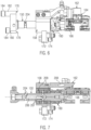
- a holder 162 is provided in a rotationally fixed manner to the actuating sleeve 158, which at its free end has a part that partially projects beyond the opening of the holding shaft 106 and in any case in Figure 6 partially laying air knotter block 164.
- a hold-down spring 166 can be seen, which interacts with the free end of the bag clamp 108 to keep it pre-tensioned against the bag 6.
- this hold-down spring 166 is located within a receiving cylinder 168.
- the bag clamp 108 rests on the Figure 4 upper wall of the holding shaft 106. Opposite this, the opening of the holding shaft 106 is surmounted by funnel-shaped outwardly inclined guide projections 170.
- An actuating arm 172 which is firmly connected to the actuating sleeve 158 and is provided with a cam roller 174 at its free end, projects radially from the actuating sleeve 158.
- This cam roller 74 interacts with the guide surfaces of the inner and outer opening cam 134, 136.
- the bag clamp is pivoted into the open position against the force of the clamping spring 160 and the hold-down spring 166. If there is no interaction between the cam roller 174 and the curve contour of the opening cam 134 or 136, the bag clamp 108 pivots into the position shown in Figure 6 shown closed position.
- One end of the clamping spring 160 is supported on the actuating arm 172 (cf. Figure 5 , 7 ).
- two guide arms 176, 178 are provided which extend radially in relation to the central longitudinal axis of the axle body 150 and are over which guide pins 180, 182 project in the axial direction, each of which carries cam rollers 184.
- the guide pin 182 has a greater axial extension than the guide pin 180.
- Each guide pin 180, 182 engages in a guide groove which is arranged at a position in plan view according to the Figures 2 and 3 behind the transport wheel 100 are provided with a guide disc. Details of the guide disc and the grooves recessed there are in the Figures 12 and 13 and described in detail below.
- the guide groove associated with guide pin 182 is located deeper than the guide groove associated with guide pin 180.
- the grooves cross each other. They accommodate the cam rollers 184 of the two guide pins 180, 182 with little play.
- cam roller 184 also has a freely rotating ring surface that is guided in the respective guide groove and can be brought into contact with the side walls of the groove with little friction.
- the pivoting movement of the holder 104 can be generated and precisely specified within the scope of the rotational movement of the transport wheel 100 relative to the stationary guide disk.
- the design with two guide pins 180, 182 allows a tight and precise forced guidance of the pivoting movement of the holder 104.
- a total of six stations are provided in the circumferential direction of the transport wheel 100.
- the individual holders 104 are therefore offset from one another by 60° in the circumferential direction.
- the holder 104 can be pivoted by 180° on a transport path of 120° or by exactly 90° on a transport path corresponding to 60°.
- the rotary movement of the transport wheel 100 together with the cyclic movement of the inner opening cam 134 induces the opening and closing of the bag clamp 108 in the area of the insertion station 102.
- the opening and closing of the bag clamp 108 is effected by pivoting the outer opening cam 136 while the transport wheel 100 is stationary.
- the bag clamp 108 is placed on the bag 6.
- the holder 162 is, however, held in a middle position. The relative movement between the bag clamp 108 and the holder 162 is brought about by the hold-down spring 166.
- the bag clamp 108 is placed on the bag 6.
- the holder 162 is, however, held in a middle position so that the endlessly fed material forming the label 10 can be cut off in the area of the label feed station 112 without colliding with the holder 162.
- the inner opening curve 134 is pivoted relative to the transport wheel when the transport wheel 100 is stationary. However, it is also pivoted in the opposite direction of rotation when the transport wheel 100 is rotating.
- the opening of the bag clamp 108 is effected by a cam 186 and the abutment of this cam 186 against a free lever arm 188.
- the cam 186 is formed by a disk which is pivotably mounted about a pivot axis 189 via a ball bearing.
- the actuation of the bag clamp 108 is accordingly achieved by pivoting the actuating sleeve 158 caused by the opening cams 134, 136.
- the label 10 fed into the label feed station 112 is applied against the outer surface of the air knotter block 164 in a manner to be detailed below.
- FIGS. 12 and 13 show details of a guide disk 190, in which two guide grooves milled to different depths and recessed around the circumference are provided, with reference number 192 identifying the deeper guide groove associated with the cam roller 184, while reference number 194 designates a less deeply recessed guide groove in which the cam roller 174 is received and guided.
- the guide grooves 192, 194 clearly intersect in order to guide the pivoting movement of the holder about the pivot axis S in such a way that the bag 6 can be introduced into the insertion station 102 with the base 9 facing forwards and, after pivoting through 180°, can be removed into the removal station 118 with the base 9 facing forwards.
- the guide disk 190 is cut out over a circumferential segment and has a retaining arch 195 which carries a suction channel segment 196 which is connected via suction hoses 197 to a vacuum source (not shown), for example a suction pump, so that a vacuum is permanently acting within a suction channel marked 198, which draws air in the direction of the suction channel 198.
- the suction channel 198 is ring-segment-shaped and has a constant radius relative to the axis of rotation D of the transport wheel 100.
- the suction channel 198 is divided into two and is placed under vacuum by two separate suction hoses 197, so that a constant vacuum can be maintained with high precision over the circumferential extent of the suction channel 198.
- a blow opening 199 which is recessed in the suction channel segment 198 and communicates with an overpressure source via a blow hose 200.
- the suction channel 198 is formed between the introduction station 102 and just before the connection station 114.
- the blow opening 199 is located at the level of the connection station 114.
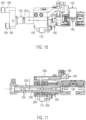
- the transport wheel 100 covers the suction channel segment 196 at the edge and forms an air guide opening 202, which communicates via non-detailed air channels within the transport wheel 100 with an inlet opening 204 recessed on the outside circumference of the holder 104 (cf. Figures 7 , 11 ).
- inlet openings 204 are provided on the circumference of the axle body 150, which has a central bore 206 which communicates with radial bores 207 which, at the level of the actuating sleeve 158, communicate with a thread channel 208 which is recessed within the holder 162 and is formed in a hose 205 on its last section up to the air knotting block 164.
- the actuating sleeve 158 is pivotally mounted relative to the axle body 150 via roller bearings 209 and for loss-free air guidance relative to the actuating sleeve 158
- the inlet openings 204 are Figure 12 shown rolling bearings, which serve to pivotally mount the holder 104 relative to the transport wheel 100.
- FIGS. 12 and 13 show the orientation of the holder 104 relative to the pivot axis S in both the insertion station 102 and the connection station 114, adjusted by the interaction of the respective cam rollers 174, 184 with the corresponding guide grooves 192, 194.
- the holding shaft 106 extends strictly radially with respect to the axis of rotation D.
- the Figure 4 and 16 respectively illustrate the designs intended to guide the thread during knotting.
- Figure 16 illustrates the air knotting block 164, which forms a thread opening 212 with a downwardly extending longitudinal slot 210, which communicates with the thread channel 208, and a deflection trough 214.
- counter plate 220 is provided, which has a deflection trough 222 and a suction opening 224, which is connected to a vacuum source for sucking out air via a suction hose 226.
- the counter plate 220 is also assigned a plunger 228, which is located in the line path between the suction hose 226 and the suction opening 224 and can be moved in the direction of the line path (cf. Figure 16 ).
- the pressure opening 206 is operatively connected to the suction channel 198 as an overpressure opening.
- a piece of hose provided with the thread 8, which receives the tea dose of the filled bag, is accordingly not only introduced into the holding shaft 106 while forming the base 9 and head 7 in the radial direction of the transport wheel 100. Rather, the thread 8 attached to the head 7 is also sucked into the thread channel 208 by the negative pressure acting and through the thread opening 212. The thread 8 is thus held in a predetermined position. There is no risk of the thread 8 getting caught on parts of the device during further processing of the bag 6. Due to the sustained suction pressure, the thread 8 is also in the thread channel 208 at the level of the label feed station 112.
- the label 10 fed in this way is pivoted by pivoting the counter plate 220 in the direction of the air knotting block 164.
- the initially flat label is deflected at its front area.
- the thread 8 connected to the head 7 is located in the longitudinal slot of the thread opening 212, so that the label 10 is clamped over its entire surface between the air knotting block 164 and the counter plate 220.
- the free end of the thread 8 is then located within the line path between the suction opening 224 and the suction hose 226.
- the tappet 228 is then actuated to clamp the thread there.
- the counter plate 220 is then pivoted away from the transport wheel 100. As the counter plate 220 moves further away from the air knotting block 164, the thread 8 is pulled tighter around the label 10 and the knot is thus tightened.
- the thread 8 is then connected to the label 10 by means of a knot.
- a cutting blade 230 of a cutting device 232 provided in the connection station 114 cuts off an end piece of the thread 8 protruding from the label 10 so that it ends essentially flush with the knot.
- the cut-off piece of thread is thereby grasped via the suction opening 224 and conveyed out through the suction hose 226.
Landscapes
- Engineering & Computer Science (AREA)
- Mechanical Engineering (AREA)
- Making Paper Articles (AREA)
- Labeling Devices (AREA)
- Package Closures (AREA)
Description
- Die vorliegende Erfindung betrifft eine Vorrichtung und ein Verfahren zum Transportieren von fertig zugeschnittenen und befüllten Schlauchstücken innerhalb einer Maschine zum Herstellen von mit brühfähigem Material gefüllten Beuteln.
- Eine gattungsgemäße Vorrichtung ist aus
EP 2 681 119 B1 bzw.EP 3 733 384 A1 bekannt. Diese Vorrichtung hat ein Transportrad, das auf seinem Umfang verteilt mehrere Beutel-Aufnahmen aufweist. - Bei dieser vorbekannten Vorrichtung wird das zugeschnittene und befüllte Schlauchstück zur Bildung eines Beutels aus dem Schlauchstück radial in das Transportrad eingebracht. Dabei wird das Schlauchstück so umgeformt, dass sich eine in Bezug auf das Transportrad radial erstreckende Kammer eines Beutels ergibt, wobei der Boden des Beutels radial innen und der Kopf des Beutels radial außen liegt. Diese Station wird auch im Rahmen der Beschreibung der vorliegenden Erfindung als Einbringstation bezeichnet. Dabei kann das zugeschnittene und befüllte Schlauchstück auch im Rahmen der Erfindung als Ein- oder Doppelkammerbeutel ausgebildet werden. Jedenfalls ist im Anschluss an die Einbringstation der zunächst ebene Zuschnitt so umgeformt, dass die Kammer und damit die Form des Beutels im Wesentlichen vorgegeben ist. Der Kopf liegt im Bereich des Außenumfangs des Transportrades frei. In nachfolgenden Bearbeitungsschritten und während das Transportrad dreht, wird dem Kopf des Beutels nach dem Stand der Technik ein Etikett zugeführt und mit dem Kopf des Beutels verbunden.
- Danach wird der Beutel in ein Längenstück einer Umhüllung eingeschlagen. Diese Umhüllung wird im Grunde U-förmig um den Beutel gelegt. Die gegeneinander liegenden Kanten der Umhüllung werden danach verschweißt, um den Beutel vollständig in der Umhüllung einzusiegeln. Die Umhüllung ist durch eine Folie gebildet, durch welche der Beutel innerhalb der Umhüllung aromadicht verpackt ist. Bei der Lösung nach
EP 2 681 119 B1 wird der Beutel dazu zunächst aus dem Transportrad in radiale Richtung entnommen und mit dem Boden nach vorne radial in das Transportrad eingebracht, wodurch die Umhüllung um den Beutel geschlagen wird. Nach der Lösung gemäßEP 3 733 384 A1 wird der Beutel in dem Transportrad verschwenkt, so dass beim Entnehmen des Beutels aus dem Transportrad der Beutel mit dem Boden nach vorne aus dem Transportrad entnommen und hierbei in die Umhüllung eingeschlagen wird. - Die Handhabung des Fadens innerhalb des Transportrades ist nicht ganz unproblematisch. Das Transportrad muss bei einer hohen Produktivität mit relativ hoher Geschwindigkeit drehen. Das Transportrad weist eine Vielzahl von Klammern, Kanten, Gelenken und Dergleichen auf, an denen sich der Faden verfangen kann.
- Der vorliegenden Erfindung liegt das Problem zugrunde, eine Vorrichtung und ein Verfahren der eingangs genannten Art anzugeben, bei denen der Faden mit höherer Sicherheit im Bereich des Transportrades gehandhabt wird.
- Zur vorrichtungsmäßigen Lösung dieser Aufgabe wird mit der vorliegenden Erfindung eine Vorrichtung mit dem Merkmal von Anspruch 1 vorgeschlagen.
- Diese Vorrichtung hat in an sich bekannter Weise ein Transportrad, das auf seinem Umfang verteilt mehrere, jeweils den Beutel haltende, Halterungen aufweist. Dem Transportrad ist eine Einbringstation zugeordnet, in der eines der Schlauchstücke in radialer Richtung zur Ausbildung eines Beutels mit zumindest einer Kammer in die Halterung eingebracht wird. Die Kammer erstreckt sich zwischen einem Kopf und einem Boden des Beutels. Der Boden des Beutels liegt dabei normalerweise radial inwärts. Der Kopf des Beutels befindet sich bereits in der Einbringstation, bevorzugt im Bereich des äußeren Umfangs des Transportrades. Auch ist eine Etiketten-Zuführstation vorgesehen, in der dem Kopf ein Etikett zugeführt wird. Des Weiteren ist eine Verbindungsstation verwirklicht, in der ein Faden mit dem Etikett und/oder dem Beutel verbunden wird. Schließlich ist in an sich bekannter Weise eine Entnahmestation vorgesehen, in der der Beutel aus dem Transportrad entnommen wird. Die zuvor erwähnten Stationen sind üblicherweise in Umfangsrichtung um das Transportrad verteilt vorgesehen. Die Etiketten-Zuführstation und die Verbindungsstation können indes an einer einheitlichen Position zwischen der Einbringstation und der Entnahmestation vorgesehen sein. An den jeweiligen Stationen wird auf den Beutel eingewirkt, um das jeweilige Leistungsergebnis in der jeweiligen Station zu erreichen.
- Allerdings kann bei der erfindungsgemäßen Lösung der Beutel kontinuierlich oder intermittierend durch Drehung des Transportrades an den jeweiligen Stationen vorbeigeführt und/oder von der jeweiligen Station weg- bzw. hingeführt werden.
- Nach der vorrichtungsmäßigen Lösung der vorliegenden Erfindung ist jeder Halterung ein Fadenkanal zugeordnet, der mit einer Unterdruckquelle und einer Überdruckquelle verbindbar ist. Der Fadenkanal ist zur Aufnahme eines Fadens angepasst ausgebildet. Dabei handelt es sich üblicherweise um ein Fadenstück. Regelmäßig ist der Faden bei Aufnahme in den Fadenkanal bereits mit dem Beutel, d.h. mit dem den Beutel umfänglich umgebenden Schlauchstück verbunden. Dementsprechend wird das Schlauchstück bereits mit dem daran befestigten Faden in der Einbringstation in das Transportrad eingebracht.
- Bei dem erfindungsgemäßen Verfahren gemäß Anspruch 7 ist der Faden vor dem Verbinden von Etikett und/oder Beutel mit dem Faden zeitweilig und während der Drehung des Transportrades in dem Fadenkanal untergebracht.
- Dabei wirkt während der Unterbringung des Fadens in dem Fadenkanal üblicherweise eine Unterdruckschwelle, durch die der Faden nicht nur in den Fadenkanal eingesogen, sondern während der Drehung des Transportrades innerhalb des Fadenkanals gehalten wird. Erst beim Verbinden des Fadens mit dem Etikett und/oder dem Beutel wird der Faden aus dem Fadenkanal ausgeblasen, so dass er außerhalb des Fadenkanals zur Befestigung mit dem Etikett und/oder dem Beutel zur Verfügung steht.
- Gemäß der erfindungsgemäßen Vorrichtung hat der Fadenkanal eine Fadenöffnung zum Einbringen des Fadens. Diese befindet sich bevorzugt benachbart zu einer Aufnahme für den eigentlichen Beutel in Form beispielsweise eines Halteschachtes. Erfindungsgemäß hat der Fadenkanal ferner eine Luftführungsöffnung, die aufgrund der Drehung des Transportrades in Wirkverbindung mit einer Unterdrucköffnung oder einer Überdrucköffnung bringbar ist. Der Fadenkanal hat danach üblicherweise lediglich zwei Öffnungen. In die Fadenöffnung wird der Faden eingebracht. Durch die Luftführungsöffnung wird das in dem Fadenkanal wirkende Druckniveau vermittelt.
- Die Wirkverbindung zwischen der Luftführungsöffnung und einer üblicherweise ortsfest vorgesehenen Unterdrucköffnung sowie einer üblicherweise ebenfalls ortsfest vorgesehenen Überdrucköffnung erfolgt aufgrund der Drehung des Transportrades. So kann durch die Drehung des Transportrades abhängig von der jeweiligen Station, an der sich die jeweilige Halterung befindet, das gewünschte Druckniveau in den Fadenkanal allein aufgrund der Drehung des Transportrades eingestellt werden. Danach sind keine aufwendigen Ventile oder dergleichen notwendig. Die Unterdrucköffnung kann für sich konstant einen Unterdruck aufweisen. Entsprechendes gilt für den Überdruck an der Überdrucköffnung. Die gewünschten Drücke werden allein durch Vorbeiführen der Luftführungsöffnung an der Unterdrucköffnung bzw. der Überdrucköffnung zwangsläufig in dem Fadenkanal eingestellt. Dadurch ergeben sich in dem Fadenkanal gerichtete Strömungen, durch die der Faden gelegt, gefördert bzw. gehalten wird.
- Im Hinblick darauf ist die Luftführungsöffnung bevorzugt an einer Oberfläche der Halterung ausgespart, die sich in Bezug auf die Drehachse des Transportrades radial erstreckt. Die in Wirkverbindung mit der Luftführungsöffnung stehende Unterdrucköffnung bzw. Überdrucköffnung ist jeweils gegenüberliegend zu der Luftführungsöffnung vorgesehen. So sind die Unterdrucköffnung und die Überdrucköffnung üblicherweise in einer gemeinsamen Ebene vorgesehen und liegen dort frei, die sich parallel zur der Radialebene des Transportrades erstreckt.
- Im Hinblick auf eine längere Wirksamkeit des Unterdrucks ist die Unterdrucköffnung als länglicher offener Kanal regelmäßig als Ringsegment ausgebildet. Die Luftführungsöffnung steht bevorzugt im Rahmen der Drehung des Transportrades von der Einbringstation bis vor die Verbindungsstation mit der Unterdrucköffnung in Wirkverbindung. Dadurch wird der Faden während der Drehung des Transportrades wirksam über den wirkenden Unterdruck in den Fadenkanal eingesogen und dort gehalten. Diese Weiterbildung verdeutlicht das Konzept einer Steuerung der Druckverhältnisse in dem Fadenkanal unter Verzicht auf Ventile oder dergleichen. Die für die Behandlung und Verarbeitung des Fadens auf dem Transportrad gewünschten Druckverhältnisse in dem Fadenkanal werden allein durch die Drehbewegung des Transportrades in den Haltekanal eingestellt, indem dessen Unterdrucköffnung abhängig von der Winkelstellung des Transportrades mit der Unterdrucköffnung und/oder der Überdrucköffnung in Wirkverbindung gebracht bzw. so angeordnet wird, dass kein Arbeitsdruck in dem Fadenkanal eingestellt wird. Dies ist beispielsweise überflüssig, nachdem der Faden mit dem Beutel und dem Etikett verbunden bzw. gegenüber dem Beutel auf dem Transportrad festgelegt ist. Entsprechendes gilt ebenso für Winkelstellungen des Transportrades, in denen die Halterung beispielsweise für die Aufnahme eines weiteren Beutels nach Abgabe an der Entnahmestation vorbereitet wird.
- Zur Befestigung des Etiketts mithilfe des Fadens steht der Fadenkanal in der Verbindungsstation mit der Überdrucköffnung in Wirkverbindung. Die Verbindungsstation hat eine Fadenführung, die unter Zwischenlage des Etiketts gegenüberliegend zu der Fadenöffnung des Fadenkanals angeordnet werden kann. Diese Fadenführung nimmt den aus dem Fadenkanal ausgeblasenen Faden auf und lenkt diesen um. Durch den wirkenden Überdruck kann der Faden mehrfach umgelenkt und durch die das Etikett enthaltende Ebene hindurchgeblasen werden, so dass der Faden an dem Etikett vorbei und/oder durch Ausnehmungen innerhalb des Etiketts hindurchgeführt und mit dem Etikett auf diese Weise verknotet wird. Details dazu sind
EP 1 731 295 B1 zu entnehmen, deren Offenbarungsgehalt durch diesen Verweis in den Offenbarungsgehalt der vorliegenden Anmeldung übernommen wird. Die zuvor diskutierte Weiterbildung führt jedenfalls zu einem durch eine Luftführung gebildeten Knoten, durch den das Etikett mit dem Faden verbunden wird. Zur Schaffung einer größeren Nähe zwischen dem Etikett und dem Beutel ist zumindest der die Fadenöffnung aufweisende Abschnitt des Fadenkanals beweglich vorgesehen, um nach Einführen des Beutels in die Aufnahme für das Befestigen des Fadens an dem Etikett in der Verbindungsstation näher an den Kopf des Beutels herangebracht zu werden. Durch diese Ausgestaltung lässt sich das Etikett in größerer Nähe zu dem Beutel mit diesem verbinden und infolgedessen oder in einer nachfolgenden Station so an dem Beutel befestigen, dass der Faden und das Etikett zumindest bis zum Einschlagen in die Umhüllung im Rahmen einer Entnahme von Beutel, Faden und Etikett als Einheit gehandhabt werden kann. Ein Abschnitt des Fadenkanals, der die Fadenöffnung ausbildet, kann dazu verschwenkbar an der Halterung angeordnet sein. - Gemäß einer bevorzugten Weiterbildung der vorliegenden Erfindung hat das Transportrad zu jeder Halterung eine Bohrung. In dieser Bohrung ist ein die Halterung tragender Achskörper um eine Schwenkachse verschwenkbar gelagert. Des Weiteren ist eine Führung vorgesehen, die der Halterung während der Drehung des Transportrades eine Orientierung in Bezug auf die Schwenkachse aufprägt. Dadurch kann beispielsweise die Halterung insgesamt im Rahmen der Drehbewegung des Transportrades verschwenkt werden, so dass beim Einbringen des Beutels in die Halterung der Boden in Einbringrichtung vorne ist, während in der Ausbringstation durch eine Verschwenkbewegung der Halterung im Wesentlichen um 180° der Beutel mit dem Boden nach vorne entnommen wird. Dadurch lassen sich die Vorteile gemäß
EP 3 733 384 B3 erzielen. Vielmehr aber noch bewirkt die Führung, dass eine exzentrisch zu der Schwenkachse angeordnete Luftführungsöffnung des Fadenkanals in der Einbringstation mit der Unterdrucköffnung und in der Verbindungsstation mit der Überdrucköffnung in Wirkverbindung steht. Dabei kann die Orientierung der Halterung in Bezug auf die Schwenkachse in der Einbringstation und in der Verbindungsstation die Gleiche bleiben. Allerdings kann die Unterdrucköffnung auch einen anderen radialen Abstand von der Drehachse des Transportrades haben als die Überdrucköffnung, so dass durch Verschwenken der Halterung um die Schwenkachse wahlweise die Luftführungsöffnung mit der Unterdrucköffnung bzw. der Überdrucköffnung in Wirkverbindung gebracht werden kann. - Zur Festlegung der Lage in Bezug auf die Schwenkachse abhängig von der Drehbewegung des Transportrades hat der Achskörper bevorzugt zumindest einen sich quer zu der Schwenkachse des Achskörpers abgehenden Führungsarm, dessen freies Ende in einer Führung vorgesehen ist. Dazu weist der Führungsarm üblicherweise einen Führungszapfen auf, der in einer Führungsnut geführt ist, die in einer Scheibe ausgespart ist, die auf der der Halterung gegenüberliegenden Seite des Transportrades vorgesehen ist. Diese Führungsscheibe bildet die Unterdrucköffnung bzw. die Überdrucköffnung aus oder trägt Mittel zur Ausbildung der entsprechenden Öffnungen.
- Gemäß ihrem nebengeordneten Aspekt schlägt die vorliegende Erfindung eine Halterung zur Halterung eines mit brühfähigem Material gefühlten Beutels vor. Diese Halterung hat einen Fadenkanal, der mit einer Druckquelle verbindbar ist. Dies bedingt, dass die Halterung eine üblicherweise benachbart zu einer Aufnahme der Halterung für den Beutel vorgesehene erste Öffnung für das Einbringen des zumindest mit dem Etikett oder dem Beutel verbundenen Fadens und eine zweite, mit dieser ersten Öffnung über den Fadenkanal verbundene Luftführungsöffnung aufweist, die mit der Druckquelle fluidisch verbindbar ist. Dies bedeutet, dass die Luftführungsöffnung so mit der Druckquelle verbunden werden kann, dass die Druckquelle den Innendruck in dem Fadenkanal soweit beeinflusst, dass in dem Fadenkanal eine Strömung der Umgebungsluft der Halterung erzeugt wird, durch welche der Faden in den Fadenkanal eingesogen beziehungsweise aus diesem herausgeblasen wird.
- Bevorzugt weist diese Halterung einen Achskörper auf, der um eine Schwenkachse verschwenkbar gelagert ist. Diese Schwenkachse ist üblicherweise auch Erstreckungsachse des Fadenkanals. Die Halterung hat dementsprechend üblicherweise einen länglichen Achskörper, um den die Aufnahme für den Beutel, die beispielsweise durch einen Halteschacht ausgebildet sein kann, verschwenkbar ist, um ein üblicherweise kopfseitiges Ende des Beutels zu verschwenken und damit üblicherweise kopfseitig auszurichten, sodass der Faden und/oder das Etikett in der gewünschten Orientierung des Beutels mit diesem verbunden werden können.
- Weitere Einzelheiten und Vorteile der vorliegenden Erfindung ergeben sich aus der nachfolgenden Beschreibung eines Ausführungsbeispiels in Verbindung mit der Zeichnung. In dieser zeigen:
- Figur 1
- eine unter zur Hilfenahme der erfindungsgemäßen Vorrichtung herstellbare Verpackungseinheit, bestehend aus einem Beutel mit Etikett und Faden und einer Umhüllung;
- Figur 2
- eine Seitenansicht auf das Transportrad nach dem Ausführungsbeispiel mit verschiedenen, umfänglich um das Transportrad angeordneten Stationen;
- Figur 3
- eine Seitenansicht des Transportrades nach
Figur 2 ohne die Darstellung der Komponenten der einzelnen Stationen; - Figur 4
- eine perspektivische Seitenansicht eines Ausführungsbeispiels einer Halterung des Ausführungsbeispiels nach den
Figuren 2 und3 in einer der Offenstellung sich annähernden Stellung; - Figur 5
- eine stirnseitige Ansicht der Komponente nach
Figur 4 ; - Figur 6
- eine Seitenansicht der Komponente nach den
Figuren 4 und 5 ; - Figur 7
- eine Längsschnittansicht der Komponente nach den
Figuren 4 bis 6 ; - Figur 8
- eine Darstellung gemäß
Figur 4 in der Geschlossenstellung; - Figur 9
- eine Darstellung gemäß
Figur 5 in der Geschlossenstellung; - Figur 10
- eine Darstellung gemäß
Figur 6 in der Geschlossenstellung; - Figur 11
- eine Darstellung gemäß
Figur 8 in der Geschlossenstellung; - Figur 12
- eine Längsschnittansicht entlang der Linie XIII-XIII gemäß der Darstellung in
Figur 2 ; - Figur 13
- eine Draufsicht auf die Führungsscheibe des Ausführungsbeispiels;
- Figur 14
- eine Schnittdarstellung von auf dem Umfang des Transportrades vorgesehenen Halterungen;
- Figur 15
- ein vergrößertes Detail XIV gemäß der Darstellung in
Figur 14 ; - Figur 16
- Details der Verbindungsstation zum Verknoten des Etiketts, wobei das Luftknoterklötzchen 164 aus Darstellungsgründen aus seiner tatsächlichen Lage verschwenkt dargestellt ist und
- Figur 17
- eine Darstellung gemäß
Figur 16 mit einem gegen das Gegenplättchen angelegten Etikett. - Die
Figur 1 zeigt ein Ausführungsbeispiel einer mit Bezugszeichen 2 gekennzeichneten Verpackungseinheit bestehend aus einer Umhüllung 4, in der ein Beutel 6 mit einem an einem Kopf 7 des Beutels 6 befestigten Faden 8 und einem an dem Kopf 7 und damit gegenüberliegend zu einem Boden 9 des als Doppelkammerbeutel ausgebildeten Beutels 6 angeordneten Etikett 10 aufgenommen sind. Der Faden 8 ist dabei einerseits mit dem Etikett 10 verknotet und andererseits durch einen Schlitz 12 des Etiketts 10 hindurchgeführt und dementsprechend an dem Etikett 10 gesichert. Der Inhalt der Umhüllung wird auf diese Weise an dem nachfolgend beschriebenen Transportrad hergestellt. - Die Umhüllung 4 besteht aus einem Längenstück einer aromadichten Folie, die über eine Falz 14 zur Ausbildung von zwei aneinander liegenden Schenkeln 16 gefaltet und über zwei parallele Längsschweißnähte 18 und eine Querschweißnaht 20 versiegelt ist.
- Die Fertigstellung des in der Umhüllung 4 aufgenommenen Beutels 6 zusammen mit dem Etikett 10 erfolgt an dem nachfolgend unter Bezugnahme auf die
Figuren 2 ff. beschriebenem Transportrad, welches in den Figuren mit Bezugszeichen 100 gekennzeichnet ist. In den Ansichten nach denFiguren 2 und3 dreht das Transportrad 100 gegen den Uhrzeigersinn. Diese Drehrichtung entspricht der Transportrichtung T. Umfänglich um das Transportrad 100 sind verschiedene Stationen vorgesehen, in denen auf den Beutel 6 bzw. dem Faden 8 oder das Etikett 10 eingewirkt wird. Bei Bezugszeichen 102 ist eine Einbringstation vorgesehen, in welcher der Beutel 6 zusammen mit dem daran bereits befestigten Faden 8 in das Transportrad 100 eingebracht wird. Dazu hat das Transportrad 100 eine in denFiguren 3 bis 7 detaillierte Halterung 104, die eine Aufnahme in Form eines den Beutel 6 aufnehmenden Halteschachtes 106 umfasst, dem eine Beutelklemme 108 zugeordnet ist, die den Beutel 6 in der Halterung 104 fixiert. - Wie
Figur 2 verdeutlicht, ist der Halteschacht 106 in der Einbringstation 102 streng radial ausgerichtet, sodass der Beutel 6 durch radiales Einstopfen in die Halterung 104 in den Halteschacht 106 eingeschoben werden kann. - In
Figur 2 ist ein bogenförmiges Einbringsegment 110 zu erkennen, welches alternierend bewegt wird, um im Rahmen der Ausbildung des Beutels 6 ein Schlauchstück unter Ausbildung zumindest einer Kammer des Beutels in die jeweilige Halterung 104 einzuschieben. Dabei wird die Drehung des Transportrades 100 jeweils unterbrochen. Dementsprechend wird das Transportrad 100 im Rahmen der weiteren Bearbeitung des Beutels 6 zyklisch drehend angetrieben, wobei das Transportrad 100 während der jeweiligen Bearbeitungsschritte steht. - In Transportrichtung T der Einbringstation 102 benachbart befindet sich eine Etiketten-Zuführstation 112, in welcher ein zugeschnittenes, mit einem Schlitz und Löchern für das Durchführen des Fadens 8 versehenes Etikett 10 dem Kopf 7 des Beutels 6 zugeführt wird. Die Halterung 104 hat dabei eine gegenüber der Orientierung in der Einbringstation 102 unveränderte radiale Ausrichtung. Entsprechendes gilt für eine sich in Transportrichtung T anschließende Verbindungsstation 114, in welcher bei dem Ausführungsbeispiel der Faden 8 mit dem Etikett 10 verknotet wird.
- Im Anschluss an die Verbindungsstation 114 wird die Halterung 104 verschwenkt, sodass diese Halterung 104 in der mit Bezugszeichen 116 gekennzeichneten Faden-Sicherungsstation 116 um 90° verschwenkt ist und sich dementsprechend relativ zu einer Drehachse D des Transportrades 100 tangential erstreckt. In dieser Faden-Sicherungsstation 116 wird der Faden 8 in den Schlitz 12 des Etiketts 10 eingeschoben. So wird der Faden 8 dem Etikett 10 und danach dem Beutel 6 zugeordnet, um zu verhindern, dass beim nachfolgenden Umhüllen des Beutels der Faden die Versieglung der Ränder des Umhüllungsmaterials durchsetzt oder sich gar an Teilen der Vorrichtung bei der weiteren Handhabung des Beutels 4 zusammen mit dem Etikett 10 und dem Faden 8 verfängt.
- Mit Bezugszeichen 118 ist eine Entnahmestation gekennzeichnet. In dieser Entnahmestation 118 ist der Beutel 6 gegenüber seiner Ausrichtung in der Einbringstation 102 um 180° gedreht. Während der Beutel 6 in der Einbringstation 102 mit seinem Boden 9 nach vorne in die Halterung 104 eingebracht wird, wird beim radialen Ausschieben des Beutels 6 in der Entnahmestation 118 der Beutel 6 mit dem Boden 9 nach vorne ausgeschoben.
- Zwischen der Entnahmestation 118 und der Einbringstation 102 befindet sich in der Transportrichtung der Entnahmestation 118 nachgelagert eine Verschwenkstation 120, in welcher die Halterung 104 um 180° verschwenkt wird, sodass diese für die Aufnahme eines neuen Beutels 6 in der Einbringstation 102 angemessen ausgerichtet wird.
- Wie
Figur 3 erkennen lässt, wird der Beutel 6 in der Entnahmestation von einer Beutelhandhabungseinrichtung 122 in der Halterung 104 gegriffen und radial aus der Halterung 104 herausgezogen. Die Beutelhandhabungseinrichtung 122 hat dafür vorlaufende und nachlaufende Arme 124, die den Beutel im Bereich des Bodens 9 klemmen und radial aus der Halterung 104 herausziehen (vgl.Figur 2 ). Diesen Armen 124 vorgelagert sind inFigur 2 dargestellte vorlaufende und nachlaufende Arme 126 einer Umhüllungsmaterialhandhabungseinrichtung 128, die das tangential über eine Umhüllungsmaterialführung 130 an dem Transportrad 100 vorbeigeführte Umhüllungsmaterial zur Ausbildung der Falz 14 greifen und radial ausfördern (vgl.Figur 2 ). - In
Figur 3 ist neben dem Transportrad 100 ein Siegeltransportrad 132 einer Siegelstation gezeigt, welches die Umhüllung 4 zusammen mit dem Beutel 6, dem Faden 8 und dem Etikett 10 in sich aufnimmt, wobei das Material der Umhüllung 4 bereits mit der Falz 14 versehen ist und der der Falz 14 gegenüberliegende Querrand sowie die beiden Längsränder von einer Schweißeinrichtung, die in Bezug auf die Drehachse D des Siegeltransportrades 132 dem Transportrad 100 im Wesentlichen gegenüber liegt, verschweißt werden und dementsprechend der Beutel 6 zusammen mit dem Etikett 10 und dem Faden 8 aromadicht eingesiegelt wird. - Die
Figuren 2 und3 lassen radial innen eine ortsfeste innere Öffnerkurve 134 erkennen, die die Beutelklemme 108 zum Einbringen des Beutels 6 in der Einbringstation 102 in die Offenstellung verschwenkt. An der Entnahmestation 118 ist eine ebenfalls nicht mit dem Transportrad 100 drehende äußere Öffnerkurve 136 gezeigt, die an einem verschwenkbar betätigbarem Hebel befestigt ist und die Beutelklemme 108 zum Entnehmen des Beutels in der Entnahmestation 118 von dem Beutel 6 abhebt. - Die
Figuren 4 bis 11 zeigen Details der Halterung 104. - Jede Halterung 104 hat einen Achskörper 150, der über ein Kugellager 152, das in einer Bohrung 154 (vgl.
Figur 3 ) des Transportrades 100 eingebracht und dort gelagert ist, frei drehbar an dem Transportrad 100 gehalten ist. An dem freien Ende des Achskörpers 150 befindet sich der Halteschacht 106. In diesem Halteschacht 106 ist die Beutelklemme 108 verschwenkbar gelagert. Mit Bezugszeichen 156 ist eine Schwenkachse für die Schwenkbewegung der Beutelklemme 108 gekennzeichnet. Die Beutelklemme 108 ist verdrehfest mit einer Betätigungshülse 158 verbunden, die über eine Klemmfeder 160 gegenüber dem Achskörper 150 vorgespannt gehalten ist. Verdrehfest mit der Betätigungshülse 158 ist ein Halter 162 vorgesehen, der an seinem freien Ende ein die Öffnung des Halteschachtes 106 teilweise überragendes und jedenfalls inFigur 6 teilweise verlegendes Luftknoterklötzchen 164 trägt. In der Geschlossenstellung nachFigur 6 ist eine Niederhalterfeder 166 zu erkennen, die mit dem freien Ende der Beutelklemme 108 zusammenwirkt, um diese gegen den Beutel 6 vorgespannt zu halten. In der Offenstellung befindet sich diese Niederhalterfeder 166 innerhalb eines Aufnahmezylinders 168. In der Offenstellung liegt die Beutelklemme 108 an der inFigur 4 oberen Wand des Halteschachtes 106 an. Gegenüberliegend dazu wird die Öffnung des Halteschachtes 106 von trichterförmig nach außen geneigten Führungsvorsprüngen 170 überragt. - Von der Betätigungshülse 158 ragt radial ein fest mit dieser Betätigungshülse 158 verbundener Betätigungsarm 172 ab, der an seinem freien Ende mit einer Kurvenrolle 174 versehen ist. Diese Kurvenrolle 74 wirkt mit den Führungsflächen der inneren und äußeren Öffnerkurve 134, 136 zusammen. Dadurch wird die Beutelklemme entgegen der Kraft der Klemmfeder 160 und der Niederhalterfeder 166 in die Offenstellung verschwenkt. Fehlt ein Zusammenwirken von Kurvenrolle 174 und Kurvenkontur der Öffnerkurve 134 bzw. 136, verschwenkt die Beutelklemme 108 in die in
Figur 6 gezeigte geschlossene Stellung. Ein Ende der Klemmfeder 160 wird an dem Betätigungsarm 172 abgestützt (vgl.Figur 5 ,7 ). - An dem dem Halteschacht 106 gegenüberliegende Ende des Achskörpers 150 sind zwei radial in Bezug auf die Mittellängsachse des Achskörpers 150 abgehende Führungsarme 176, 178 vorgesehen, die in axialer Richtung von Führungszapfen 180, 182 überragt sind, die jeweils Kurvenrollen 184 tragen. Dabei hat der Führungszapfen 182 eine größere axiale Erstreckung als der Führungszapfen 180.
- Jeder Führungszapfen 180, 182 greift in jeweils eine Führungsnut ein, die an einer in der Draufsicht nach den
Figuren 2 und3 hinter dem Transportrad 100 ortsfest vorgesehenen Führungsscheibe ausgespart sind. Details zu der Führungsscheibe und den dort ausgesparten Nuten sind denFiguren 12 und13 zu entnehmen und nachfolgend detailliert beschrieben. Die dem Führungszapfen 182 zugeordnete Führungsnut liegt dabei tiefer als die dem Führungszapfen 180 zugeordnete Führungsnut. Die Nuten kreuzen einander. Sie nehmen die Kurvenrollen 184 der beiden Führungszapfen 180, 182 mit wenig Spiel in sich auf. Wie die Kurvenrolle 174 hat auch die Kurvenrolle 184 eine frei drehbare Ringfläche, die in der jeweiligen Führungsnut geführt ist und an den Seitenwänden der Nut reibungsarm zur Anlage gebracht werden kann. - Durch die drehbare Lagerung des Achskörpers 150 über das Kugellager 152 gegenüber dem sich drehenden Transportrad 100 und den beiden exzentrisch zu der Schwenkachse der Halterung 104, die durch die Mittellängsachse der Achskörpers 150 gebildet ist, vorgesehenen Führungszapfen 180, 182 kann die Verschwenkbewegung der Halterung 104 im Rahmen der Drehbewegung des Transportrades 100 relativ zu der ortsfesten Führungsscheibe erzeugt und exakt vorgegeben werden.
- Die Ausgestaltung mit zwei Führungszapfen 180, 182 erlaubt dabei eine enge und präzise Zwangsführung der Schwenkbewegung der Halterung 104. Wie die Draufsicht nach den
Figuren 2 und3 vermittelt, sind in Umfangsrichtung des Transportrades 100 insgesamt sechs Stationen vorgesehen. Die einzelnen Halterungen 104 sind dementsprechend um 60° in Umfangsrichtung versetzt zueinander vorgesehen. Dabei kann auf einem Transportweg von 120° die Halterung 104 um 180° bzw. auf einem Transportweg entsprechend 60° um exakt 90° verschwenkt werden. - Bei dem Ausführungsbeispiel induziert die Drehbewegung des Transportrades 100 zusammen mit der zyklischen Bewegung der inneren Öffnerkurve 134 das Öffnen und Schließen der Beutelklemme 108 im Bereich der Einbringstation 102. In der Entnahmestation 118 wird das Öffnen und Schließen der Beutelklemme 108 durch Verschwenken der äußeren Öffnerkurve 136 bewirkt, während das Transportrad 100 steht. Dabei wird - wie
Figur 3 belegt - zwar die Beutelklemme 108 an den Beutel 6 angelegt. Der Halter 162 wird aber auf einer mittleren Position gehalten. Die Relativbewegung zwischen der Beutelklemme 108 und dem Halter 162 wird durch die Niederhalterfeder 166 bewirkt. In der Etiketten-Zuführstation 112 ist die Beutelklemme 108 an den Beutel 6 angelegt. Der Halter 162 wird indes auf einer mittleren Position gehalten, sodass das endlos zugeführte und das Etikett 10 ausbildende Material im Bereich der Etiketten-Zuführstation 112 abgeschnitten werden kann, ohne mit dem Halter 162 zu kollidieren. Die innere Öffnerkurve 134 wird bei stehendem Transportrad 100 relativ zu dem Transportrad verschwenkt. Sie wird aber auch bei drehendem Transportrad 100 entgegen seiner Drehrichtung verschwenkt. - Das Öffnen der Beutelklemme 108 wird über einen Nocken 186 und Anlage dieses Nocken 186 gegen einen freien Hebelarm 188 bewirkt. Der Nocken 186 wird durch eine Scheibe gebildet, die über ein Kugellager um eine Schwenkachse 189 verschwenkbar gelagert ist. Die Betätigung der Beutelklemme 108 ergibt sich dementsprechend durch Verschwenken der Betätigungshülse 158 veranlasst durch die Öffnerkurven 134, 136.
- Das in der Etiketten-Zuführstation 112 zugeführte Etikett 10 wird in einer nachstehend noch detaillierten Weise gegen die Außenfläche des Luftknoterklötzchens 164 angelegt.
- Die
Figuren 12 und13 zeigen Details einer Führungsscheibe 190, in der zwei unterschiedlich tief eingefräste, umfänglich ausgesparte Führungsnuten vorgesehen sind, wobei mit Bezugszeichen 192 die tiefere und der Kurvenrolle 184 zugeordnete Führungsnut gekennzeichnet ist, während mit Bezugszeichen 194 eine weniger tief ausgesparte Führungsnut ausgebildet ist, in welcher die Kurvenrolle 174 aufgenommen und geführt ist. Ersichtlich schneiden sich die Führungsnuten 192, 194, um die Verschwenkbewegung der Halterung um die Schwenkachse S so führen, dass der Beutel 6 mit dem Boden 9 nach vorne in der Einbringstation 102 eingebracht und nach Verschwenken um 180° in der Entnahmestation 118 mit dem Boden 9 nach vorne entnommen werden kann. Die Führungsscheibe 190 ist über ein Umfangssegment ausgeschnitten und weist einen Haltebogen 195 auf, der ein Saugkanalsegment 196 trägt, das über Saugschläuche 197 mit einer nicht gezeigten Unterdruckquelle, beispielsweise einer Saugpumpe, in Verbindung steht, so dass innerhalb eines mit 198 gekennzeichneten Saugkanals permanent ein Unterdruck wirkt, der Luft in Richtung auf den Saugkanal 198 abzieht. Der Saugkanal 198 ist ringsegmentförmig und mit einem konstanten Radius relativ zu der Drehachse D des Transportrades 100 ausgebildet. Der Saugkanal 198 ist zweigeteilt und wird von zwei separaten Saugschläuchen 197 unter Unterdruck gesetzt, sodass sich über die Umfangserstreckung des Saugkanals 198 ein gleichbleibender Unterdruck mit hoher Genauigkeit aufrechterhalten lässt. In Transportrichtung T im Anschluss an den Saugkanal 198 befindet sich eine Blasöffnung 199, die in dem Saugkanalsegment 198 ausgespart ist und über einen Blasschlauch 200 mit einer Überdruckquelle kommuniziert. - Der Saugkanal 198 ist zwischen der Einbringstation 102 bis kurz vor die Verbindungsstation 114 ausgebildet. Die Blasöffnung 199 befindet sich auf Höhe der Verbindungsstation 114.
WieFigur 12 verdeutlicht, überdeckt das Transportrad 100 randseitig das Saugkanalsegment 196 und bildet eine Luftführungsöffnung 202 aus, die über nicht detaillierte Luftkanäle innerhalb des Transportrades 100 mit einer außenumfänglich an der Halterung 104 ausgesparten Eintrittsöffnung 204 kommuniziert (vgl.Figuren 7 ,11 ). Wie insbesondere dieFiguren 4 und7 bzw. 8 und11 erkennen lassen, sind mehrere Eintrittsöffnungen 204 an dem Umfang des Achskörpers 150 vorgesehen, der eine mittlere Bohrung 206 aufweist, die mit Radialbohrungen 207 kommuniziert, die auf Höhe der Betätigungshülse 158 mit einem Fadenkanal 208 kommunizieren, der innerhalb des Halters 162 ausgespart und auf seinem letzten Teilstück bis zu dem Luftknoterklötzchen 164 in einem Schlauch 205 ausgebildet ist. Wie insbesondere dieFiguren 7 und11 verdeutlichen, ist die Betätigungshülse 158 über Wälzlager 209 relativ zu dem Achskörper 150 verschwenkbar gelagert und zur verlustfreien Luftführung gegenüber der Betätigungshülse 158 abgedichtet. In gleicher Weise sind die Eintrittsöffnungen 204 von hier inFigur 12 gezeigten Wälzlagern umgeben, die der verschwenkbaren Lagerung der Halterung 104 gegenüber dem Transportrad 100 dienen. - Die
Figuren 12 und13 zeigen die Ausrichtung der Halterung 104 relativ zu der Schwenkachse S sowohl in der Einbringstation 102 wie auch der Verbindungsstation 114, eingestellt durch das Zusammenwirken der jeweiligen Kurvenrollen 174, 184 mit den entsprechenden Führungsnuten 192, 194. Dabei erstreckt sich der Halteschacht 106 in Bezug auf die Drehachse D streng radial. - Die
Figur 4 bzw. 16 verdeutlichen die zur Führung des Fadens beim Verknoten vorgesehenen Gestaltungen. -
Figur 16 verdeutlicht das Luftknoterklötzchen 164, das eine mit einem nach unten abgehenden Längsschlitz 210 ausgebildete Fadenöffnungen 212, die mit dem Fadenkanal 208 kommuniziert, und eine Umlenkmulde 214 ausbildet. Auf der gegenüberliegenden Seite ist ein in denFiguren 15 bis 17 gezeigtes Gegenplättchen 220 vorgesehen, welches eine Umlenkmulde 222 und eine Saugöffnung 224 aufweist, die über einen Saugschlauch 226 mit einer Unterdruckquelle zum Absaugen von Luft verbunden ist. Dem Gegenplättchen 220 ist ferner ein Stößel 228 zugeordnet, der in dem Leitungsweg zwischen dem Saugschlauch 226 und der Saugöffnung 224 befindlich ist und in Richtung auf den Leitungsweg zugestellt werden kann (vgl.Figur 16 ). - In der Einbringstation steht die Drucköffnung 206 in Wirkverbindung mit dem Saugkanal 198 als Überdrucköffnung. Ein mit dem Faden 8 versehenes Schlauchstück, welches die Teedosis des gefüllten Beutels in sich aufnimmt, wird dementsprechend nicht nur unter Ausformung von Boden 9 und Kopf 7 in radialer Richtung des Transportrades 100 in den Halteschacht 106 eingebracht. Vielmehr wird auch der an dem Kopf 7 befestigte Faden 8 durch den wirkenden Unterdruck und durch die Fadenöffnung 212 in den Fadenkanal 208 eingesogen. Damit wird der Faden 8 an vorbestimmter Position gehalten. Es besteht nicht die Gefahr, dass der Faden 8 sich an Teilen der Vorrichtung im Rahmen der weiteren Bearbeitung des Beutels 6 verfängt. Durch den anhaltenden Saugdruck ist der Faden 8 auch noch auf Höhe der Etiketten-Zuführstation 112 in dem Fadenkanal 208.
- Wie
Figur 15 verdeutlicht, wird das so zugeführte Etikett 10 durch Verschwenken des Gegenplättchens 220 in Richtung auf das Luftknoterklötzchen 164 verschwenkt. Dabei wird das zunächst ebene Etikett an seinem vorderen Bereich umgelenkt. Der mit dem Kopf 7 verbundene Faden 8 befindet sich in dem Längsschlitz der Fadenöffnung 212, sodass das Etikett 10 vollflächig zwischen dem Luftknoterklötzchen 164 und dem Gegenplättchen 220 geklemmt ist. - Wie sich leicht mit
Figur 17 vorstellen lässt, bei welcher das Luftknoterklötzchen 164 aus Darstellungszwecken von dem Etikett 10 weggeschwenkt ist, wird der aus dem Fadenkanal 208 ausgeblasene Faden 8 durch die Fadenöffnung 212 ausgeblasen und durch das erste Durchgangsloch 11a des Etiketts 10 hindurchgeblasen. In dem Gegenplättchen 220 wird der Faden 8 in der Umlenkmulde 222 um die Saugöffnung 224 herum und über die Ebene des Etiketts 10 hinausgeführt und dort auf die dem Etikett 10 gegenüberliegende Seite in die Umlenkmulde 214 des Luftknoterklötzchens 164 überführt. Der Faden 8 wird innerhalb des Luftknoterklötzchens 164 und der dort vorgesehenen Umlenkmulde 214 nach innen und auf Höhe der Fadenöffnung 212 zurückgeführt und durch das zweite Durchgangsloch 11b und von dort durch die Saugöffnung 242 geführt. Das freie Ende des Fadens 8 befindet sich danach innerhalb des Leitungsweges zwischen der Saugöffnung 224 und dem Saugschlauch 226. Sodann wird der Stößel 228 betätigt, um den Faden dort zu klemmen. Danach wird das Gegenplättchen 220 von dem Transportrad 100 weggeschwenkt. Mit zunehmender Entfernung des Gegenplättchens 220 von dem Luftknoterklötzchen 164 wird der Faden 8 enger um das Etikett 10 gezogen und damit der Knoten festgezurrt. - Danach ist der Faden 8 mittels eines Knotens mit dem Etikett 10 verbunden. Ein in der Verbindungsstation 114 vorgesehenes Schneidmesser 230 einer Schneideinrichtung 232 trennt ein von dem Etikett 10 abragendes Endstück des Fadens 8 ab, so dass dieser im Wesentlichen bündig mit dem Knoten endet. Das abgeschnittene Fadenstück wird dabei über die Saugöffnung 224 erfasst und durch den Saugschlauch 226 ausgefördert.
-
- 2
- Verpackungseinheit
- 4
- Umhüllung
- 6
- Beutel
- 7
- Kopf
- 8
- Faden
- 9
- Boden
- 10
- Etikett
- 11a
- erstes Durchgangsloch
- 11b
- zweites Durchgangsloch
- 12
- Schlitz
- 14
- Falz
- 16
- Schenkel
- 18
- Längsschweißnaht
- 20
- Querschweißnaht
- 100
- Transportrad
- 102
- Einbringstation
- 104
- Halterung
- 106
- Halteschacht
- 108
- Beutelklemme
- 110
- Einbringsegment
- 112
- Etiketten-Zuführstation
- 114
- Verbindungsstation
- 116
- Faden-Sicherungsstation
- 118
- Entnahmestation
- 120
- Verschwenkstation
- 122
- Beutelhandhabungseinrichtung
- 124
- Arme
- 126
- Arme
- 128
- Umhüllungshandhabungseinrichtung
- 130
- Umhüllungsmaterialführung
- 132
- Siegeltransportrad
- 134
- Innere Öffnerkurve
- 136
- Äußere Öffnerkurve
- 150
- Achskörper
- 152
- Kugellager
- 154
- Bohrung
- 156
- Schwenkachse der Beutelklemme
- 158
- Betätigungshülse
- 160
- Klemmfeder
- 162
- Halter
- 164
- Luftknoterklötzchen
- 166
- Niederhalterfeder
- 168
- Aufnahmezylinder
- 170
- Führungsvorsprung
- 172
- Betätigungsarm
- 174
- Kurvenrolle
- 176
- Führungsarm
- 178
- Führungsarm
- 180
- Führungszapfen
- 182
- Führungszapfen
- 184
- Kurvenrolle
- 186
- Nocken
- 188
- freier Hebelarm
- 189
- Schwenkachse
- 190
- Führungsscheibe
- 192
- Führungsnut zu der Kurvenrolle 184
- 194
- Führungsnut zu der Kurvenrolle 174
- 195
- Haltebogen
- 196
- Saugkanalsegment
- 197
- Saugschlauch
- 198
- Saugkanal
- 199
- Blasöffnung
- 200
- Blasschlauch
- 202
- Luftführungsöffnung
- 204
- Eintrittsöffnung
- 205
- Schlauch
- 206
- Bohrung
- 207
- Radialbohrung
- 208
- Fadenkanal
- 209
- Wälzlager
- 210
- Längsschlitz
- 212
- Fadenöffnung
- 214
- Umlenkmulde
- 220
- Gegenplättchen
- 222
- Umlenkmulde
- 224
- Saugöffnung
- 226
- Saugschlauch
- 228
- Stößel
- 230
- Schneidmesser
- 232
- Schneideinrichtung
- D
- Drehachse
- T
- Transportrichtung
- S
- Schwenkachse
Claims (8)
- Vorrichtung zum Transportieren von fertig zugeschnittenen und befüllten Schlauchstücken innerhalb einer Maschine zum Herstellen von mit brühfähigem Material gefüllten Beuteln, mit zumindest einem Transportrad (100), das auf seinem Umfang verteilt mehrere jeweils den Beutel (6) haltende Halterungen (104) aufweist, wobei eine Einbringstation (102), in der eines der Schlauchstücke in radialer Richtung zur Ausbildung eines Beutels (6) mit zumindest einer Kammer zwischen einem Kopf (7) und einem Boden (9) des Beutels (6) in die Halterung (104) eingebracht wird, eine Etiketten-Zuführstation (112), in der dem Kopf (7) ein Etikett (10) zugeführt wird, eine Verbindungsstation (114), in der ein Faden (8) mit dem Etikett (10) und/oder dem Beutel (6) verbunden wird, und eine Entnahmestation (118), in der der Beutel (6) aus dem Transportrad (100) entnommen wird, in Umfangsrichtung um das Transportrad (100) verteilt vorgesehen sind, dadurch gekennzeichnet, dass jeder Halterung (104) ein Fadenkanal (208) zugeordnet, der mit einer Unterdruckquelle und einer Überdruckquelle verbindbar und zur Aufnahme eines mit dem Beutel (6) verbundenen Fadens (8) angepasst ausgebildet ist und, dass der Fadenkanal (208) eine Fadenöffnung (212) zum Einbringen des Fadens (8) und eine gegenüberliegende Luftführungsöffnung (202) aufweist, die aufgrund der Drehung des Transportrades (100) in Wirkverbindung mit einer Unterdrucköffnung (196) oder einer Überdrucköffnung (199) bringbar ist.
- Vorrichtung nach Anspruch 1, dadurch gekennzeichnet, dass die Luftführungsöffnung (202) an einer Oberfläche ausgespart ist, die sich in Bezug auf die Drehachse (D) des Transportrades (100) radial erstreckt und dass in Wirkverbindung die Unterdrucköffnung (198) bzw. die Überdrucköffnung (199) gegenüberliegend zu der Luftführungsöffnung (202) vorgesehen ist.
- Vorrichtung nach Anspruch 1 oder 2, dadurch gekennzeichnet, dass die Unterdrucköffnung (196) als länglicher offener Kanal (198) ausgebildet ist und dass die Luftführungsöffnung (202) im Rahmen der Drehung des Transportrades (100) von der Einbringstation (102) bis vor die Verbindungsstation (114) mit dem Kanal (198) in Wirkverbindung steht.
- Vorrichtung nach einem der vorherigen Ansprüche, dadurch gekennzeichnet, dass der Fadenkanal (208) in der Verbindungsstation (114) mit der Überdrucköffnung (199) in Wirkverbindung steht und dass die Verbindungsstation (114) eine unter Zwischenlage des Etiketts (10) gegenüberliegend zu einer Fadenöffnung (212) des Fadenkanals (208) anzuordnende Fadenführung (222) aufweist, die den aus dem Fadenkanal (208) ausgeblasenen Faden (8) in Richtung auf das Etikett (10) umlenkt.
- Vorrichtung nach einem der vorherigen Ansprüche, dadurch gekennzeichnet, dass das Transportrad (100) zu jeder Halterung (104) eine Bohrung (154) aufweist, in der ein die Halterung (104) tragender Achskörper (150) um eine Schwenkachse (S) verschwenkbar gelagert ist, dass eine Führung (184, 192; 174, 194) vorgesehen ist, die der Halterung (104) während der Drehung des Transportrades (100) eine Orientierung in Bezug auf die Schwenkachse (S) aufprägt, so dass eine exzentrisch zu der Schwenkachse (S) angeordnete Luftführungsöffnung (204) des Fadenkanals (208) in der Einbringstation (102) mit der Unterdrucköffnung (198) und in der die Verbindungsstation (114) mit der Überdrucköffnung (199) in Wirkverbindung steht.
- Vorrichtung nach Anspruch 5, dadurch gekennzeichnet, dass der Achskörper (150) mit zumindest einem quer zu einer Schwenkachse (S) des Achskörpers (150) abgehenden Führungsarm (178) verbunden ist, dessen freies Ende in der Führung (184, 192; 174, 194) geführt ist.
- Verfahren zum Transportieren von fertig zugeschnittenen und befüllten Schlauchstücken innerhalb einer Maschine zum Herstellen von mit brühfähigem Material gefüllten Beuteln (6) mit einer Vorrichtung gemäß einem der Ansprüche 1 bis 6, dadurch gekennzeichnet, dass der Faden (8) vor dem Verbinden zur zeitweiligen Unterbringung während der Drehung des Transportrades (100) in einem Fadenkanal (208) untergebracht und zum Verbinden mit dem Etikett (10) aus dem Fadenkanal (208) ausgeblasen wird.
- Verfahren nach Anspruch 7, dadurch gekennzeichnet, dass der an dem Schlauchstück befestigte Faden (8) in der Einbringstation (102) in den Fadenkanal (208) eingesogen wird und zum Verknoten des Etiketts (10) aus dem Fadenkanal (208) ausgeblasen wird.
Priority Applications (6)
| Application Number | Priority Date | Filing Date | Title |
|---|---|---|---|
| EP21170188.3A EP4079647B1 (de) | 2021-04-23 | 2021-04-23 | Vorrichtung und verfahren zum transportieren von fertig zugeschnittenen und befüllten schlauchstücken |
| ES21170188T ES2991951T3 (es) | 2021-04-23 | 2021-04-23 | Dispositivo y procedimiento para transportar piezas tubulares precortadas a medida y llenas |
| PT211701883T PT4079647T (pt) | 2021-04-23 | 2021-04-23 | Dispositivo e processo para o transporte de pedaços de tubo já cortados e preenchidos |
| US17/726,085 US12338018B2 (en) | 2021-04-23 | 2022-04-21 | Device and method for transporting ready-cut and filled hose pieces |
| CN202210431615.4A CN115231076B (zh) | 2021-04-23 | 2022-04-22 | 用于输送已切割和填充的软管段的装置和方法 |
| JP2022070509A JP7317175B2 (ja) | 2021-04-23 | 2022-04-22 | 事前切断及び充填済みの複数の筒状片を搬送するための装置及び方法 |
Applications Claiming Priority (1)
| Application Number | Priority Date | Filing Date | Title |
|---|---|---|---|
| EP21170188.3A EP4079647B1 (de) | 2021-04-23 | 2021-04-23 | Vorrichtung und verfahren zum transportieren von fertig zugeschnittenen und befüllten schlauchstücken |
Publications (2)
| Publication Number | Publication Date |
|---|---|
| EP4079647A1 EP4079647A1 (de) | 2022-10-26 |
| EP4079647B1 true EP4079647B1 (de) | 2024-08-07 |
Family
ID=75690096
Family Applications (1)
| Application Number | Title | Priority Date | Filing Date |
|---|---|---|---|
| EP21170188.3A Active EP4079647B1 (de) | 2021-04-23 | 2021-04-23 | Vorrichtung und verfahren zum transportieren von fertig zugeschnittenen und befüllten schlauchstücken |
Country Status (6)
| Country | Link |
|---|---|
| US (1) | US12338018B2 (de) |
| EP (1) | EP4079647B1 (de) |
| JP (1) | JP7317175B2 (de) |
| CN (1) | CN115231076B (de) |
| ES (1) | ES2991951T3 (de) |
| PT (1) | PT4079647T (de) |
Family Cites Families (18)
| Publication number | Priority date | Publication date | Assignee | Title |
|---|---|---|---|---|
| GB829758A (en) * | 1957-02-15 | 1960-03-09 | Forgrove Mach | Improvements in wrapping machines |
| IT1001429B (it) * | 1973-12-20 | 1976-04-20 | Gd Spa | Dispositivo associabile a macchine incartatrici per determinare l in volucro di caramelle e simili ar ticoli nelle gocce d incarto cosid dette a semplice cestello o doppio fiocco |
| DE2405761C2 (de) * | 1974-02-07 | 1976-01-08 | Paul Gerhard Dipl.-Ing. Dr. 8992 Wasserburg Klar | Maschine zur Herstellung von beutelartigen Zweikammerpackungen, insbesondere von Teebeuteln |
| IT1207629B (it) * | 1987-03-09 | 1989-05-25 | Cestind Centro Studi Ind | Apparecchiatura a ruota girevole a mezzi di presa per applicare etichette e filo ad un tubo appiattito secondo sacchetti-filtro biuso in serie nelle macchine confezionatrici in continuo di detti sacchetti-filtro |
| IT1282483B1 (it) * | 1995-04-04 | 1998-03-23 | Tecnomeccanica Srl | Macchina per il confezionamento di buste-filtro contenenti un prodotto da infusione provviste di etichetta di presa collegata alla busta |
| EP0806352B1 (de) * | 1996-05-07 | 2001-11-07 | Teepack Spezialmaschinen Gmbh & Co. Kg | Doppelkammer-Aufgussbeutel, insbesondere für Tee, und Verfahren zu seiner Herstellung |
| ITBO20020480A1 (it) * | 2002-07-23 | 2004-01-23 | Tecnomeccanica Srl | Macchina per formare una busta filtro per contenimento di una sostanza da infusione con accumulo di filo associato alla etichetta di presa |
| EP1731295B1 (de) * | 2005-06-02 | 2008-03-19 | Teepack Spezialmaschinen Gmbh & Co. Kg | Vorrichtung zum Knoten von wenigstens einem flexiblen Material |
| EP1818263B1 (de) * | 2006-02-10 | 2008-07-23 | Teepack Spezialmaschinen Gmbh & Co. Kg | Verfahren zum Abpacken von Schüttgut und eine hierbei zum Einsatz kommende Vorrichtung |
| EA018135B1 (ru) * | 2008-05-20 | 2013-05-30 | Цубакимото Когьо Ко., Лтд. | Способ и установка для производства листового материала для экстракционных пакетиков |
| ITBO20110094A1 (it) * | 2011-03-01 | 2012-09-02 | Roberto Conti | Macchina per la produzione di sacchetti - filtro con prodotti da infusione e con busta di sovraincarto |
| EP3186152B1 (de) * | 2014-08-28 | 2018-11-21 | Azionaria Costruzioni Macchine Automatiche A.C.M.A. S.p.A. | Vorrichtung zur herstellung von verpackungen für aufgussprodukte |
| WO2016030000A1 (en) * | 2014-08-28 | 2016-03-03 | Azionaria Costruzioni Macchine Automatiche A.C.M.A.S.P.A. | Apparatus for producing packages of infusion products |
| JP6893884B2 (ja) * | 2015-04-30 | 2021-06-23 | イ・エンメ・ア・インダストリア・マッキネ・アウトマティケ・ソチエタ・ペル・アツィオーニI.M.A. INDUSTRIA MACCHINE AUTOMATICHE S.p.A. | パウチを移動させるためのシステムおよび方法 |
| ES2718745T3 (es) * | 2016-06-15 | 2019-07-04 | Volpak Sau | Una máquina de envasado automática para llenar una bolsa hecha de un material termosellable con una dosis de un producto suelto |
| DE102018101570A1 (de) * | 2018-01-24 | 2019-07-25 | Häussler & Sauter KG | Verfahren und Vorrichtung zur Herstellung von Aufgussbeuteln |
| DE102019101301A1 (de) * | 2019-01-18 | 2020-07-23 | Khs Gmbh | Vakuumtrommel für ein Etikettieraggregat, Etikettieraggregat mit einer solchen Vakuumtrommel sowie Verfahren zur Herstellung einer Vakuumtrommel |
| PT3733383T (pt) * | 2019-05-02 | 2023-03-15 | Teepack Spezialmaschinen Gmbh & Co Kg | Dispositivo e processo para a produção de uma saqueta dotada de um invólucro, contendo um material passível de infusão |
-
2021
- 2021-04-23 PT PT211701883T patent/PT4079647T/pt unknown
- 2021-04-23 ES ES21170188T patent/ES2991951T3/es active Active
- 2021-04-23 EP EP21170188.3A patent/EP4079647B1/de active Active
-
2022
- 2022-04-21 US US17/726,085 patent/US12338018B2/en active Active
- 2022-04-22 CN CN202210431615.4A patent/CN115231076B/zh active Active
- 2022-04-22 JP JP2022070509A patent/JP7317175B2/ja active Active
Also Published As
| Publication number | Publication date |
|---|---|
| PT4079647T (pt) | 2024-08-16 |
| CN115231076A (zh) | 2022-10-25 |
| CN115231076B (zh) | 2024-01-02 |
| JP7317175B2 (ja) | 2023-07-28 |
| JP2022167856A (ja) | 2022-11-04 |
| EP4079647A1 (de) | 2022-10-26 |
| ES2991951T3 (es) | 2024-12-05 |
| US20220340317A1 (en) | 2022-10-27 |
| US12338018B2 (en) | 2025-06-24 |
Similar Documents
| Publication | Publication Date | Title |
|---|---|---|
| DE69900236T2 (de) | Verfahren und Maschine zur Herstellung von Beuteln mit einem transversalen Reissverschluss | |
| EP3733384A1 (de) | Vorrichtung und verfahren zum transportieren von fertig zugeschnittenen und befüllten schlauchstücken | |
| DE2622393C3 (de) | Vorrichtung zum Verpacken von Gegenständen | |
| DE3830084A1 (de) | Verfahren und vorrichtung an einer maschine zur herstellung von briefhuellen und dergleichen zum befestigen von klammern | |
| DE3008633C2 (de) | ||
| DE3131687A1 (de) | "verpackungs-vorrichtung zum herstellen von zuschnitten und zufuehren derselben in einer verpackungsstation" | |
| EP0350590A1 (de) | Verfahren zum Anbringen eines Trinkhalmes an einer Packung und Vorrichtung zur Durchführung dieses Verfahrens | |
| DE2162874C3 (de) | Einrichtung zum Kleben eines Scheitelstreifens aus Kautschuk auf einen Wulstring für Luftreifen | |
| DE3619714A1 (de) | Zufuhrvorrichtung fuer steuerbanderolen in einer zigaretten-verpackungsmaschine | |
| DE3807763C2 (de) | Vorrichtung zum Zuführen und Anbringen von Etiketten, Faden und Verbindungsabschnitten an Filterbeuteln für Aufgußprodukte | |
| DE2306598C3 (de) | Vorrichtung zum drehbaren Halten zylindrischer Gegenstände, insbesondere Ampullen, in einer Rotationsdruckmaschine | |
| EP0304736A2 (de) | Verfahren und Vorrichtung zum Einhüllen von insbesondere Zigaretten-Packungen | |
| DE6752577U (de) | Vorrichtung zum verpacken eines verpackungskoerpers. | |
| DE2302700A1 (de) | Vorrichtung zur behandlung von packungen | |
| DE2405761B1 (de) | Maschine zur Herstellung von beutelartigen Zweikammerpackungen,insbesondere von Teebeuteln | |
| DE2853053C2 (de) | ||
| DE2120270B2 (de) | Vorrichtung zum Herstellen von gefalteten Zweikammer-Beuteln aus schmiegsamem, aufgußfähigem Werkstoff | |
| EP0586926B1 (de) | Vorrichtung zum Schneiden und Heften von mehrlagigen Druckprodukten in Falzapparaten | |
| EP4079647A1 (de) | Vorrichtung und verfahren zum transportieren von fertig zugeschnittenen und befüllten schlauchstücken sowie entsprechende halterung | |
| DE2215965A1 (de) | Maschine zum Evakuieren und dichten Verschließen von Tüten o.dgl | |
| DE3814097C2 (de) | Maschine zur Befeuchtung eines an einem Unterteil zu befestigenden Deckels | |
| DE3727990C2 (de) | ||
| DE102018008483B3 (de) | Verfahren zum Verpacken von portionierten, im Verarbeitungszustand flüssigen oder pastösen Produkten und Verpackungsmaschine zur Durchführung eines solchen Verfahrens | |
| DE2326649A1 (de) | Vorrichtung und verfahren zum verpacken von gegenstaenden in beuteln | |
| DE2145087A1 (de) | Maschine für die Vakuumverpackung von verschiedenartigen Produkten, insbesondere von Lebensmitteln |
Legal Events
| Date | Code | Title | Description |
|---|---|---|---|
| PUAI | Public reference made under article 153(3) epc to a published international application that has entered the european phase |
Free format text: ORIGINAL CODE: 0009012 |
|
| STAA | Information on the status of an ep patent application or granted ep patent |
Free format text: STATUS: REQUEST FOR EXAMINATION WAS MADE |
|
| 17P | Request for examination filed |
Effective date: 20211209 |
|
| AK | Designated contracting states |
Kind code of ref document: A1 Designated state(s): AL AT BE BG CH CY CZ DE DK EE ES FI FR GB GR HR HU IE IS IT LI LT LU LV MC MK MT NL NO PL PT RO RS SE SI SK SM TR |
|
| P01 | Opt-out of the competence of the unified patent court (upc) registered |
Effective date: 20230413 |
|
| STAA | Information on the status of an ep patent application or granted ep patent |
Free format text: STATUS: EXAMINATION IS IN PROGRESS |
|
| 17Q | First examination report despatched |
Effective date: 20231011 |
|
| GRAP | Despatch of communication of intention to grant a patent |
Free format text: ORIGINAL CODE: EPIDOSNIGR1 |
|
| STAA | Information on the status of an ep patent application or granted ep patent |
Free format text: STATUS: GRANT OF PATENT IS INTENDED |
|
| GRAJ | Information related to disapproval of communication of intention to grant by the applicant or resumption of examination proceedings by the epo deleted |
Free format text: ORIGINAL CODE: EPIDOSDIGR1 |
|
| STAA | Information on the status of an ep patent application or granted ep patent |
Free format text: STATUS: EXAMINATION IS IN PROGRESS |
|
| INTG | Intention to grant announced |
Effective date: 20240226 |
|
| INTC | Intention to grant announced (deleted) | ||
| GRAP | Despatch of communication of intention to grant a patent |
Free format text: ORIGINAL CODE: EPIDOSNIGR1 |
|
| STAA | Information on the status of an ep patent application or granted ep patent |
Free format text: STATUS: GRANT OF PATENT IS INTENDED |
|
| INTG | Intention to grant announced |
Effective date: 20240429 |
|
| GRAS | Grant fee paid |
Free format text: ORIGINAL CODE: EPIDOSNIGR3 |
|
| GRAA | (expected) grant |
Free format text: ORIGINAL CODE: 0009210 |
|
| STAA | Information on the status of an ep patent application or granted ep patent |
Free format text: STATUS: THE PATENT HAS BEEN GRANTED |
|
| AK | Designated contracting states |
Kind code of ref document: B1 Designated state(s): AL AT BE BG CH CY CZ DE DK EE ES FI FR GB GR HR HU IE IS IT LI LT LU LV MC MK MT NL NO PL PT RO RS SE SI SK SM TR |
|
| REG | Reference to a national code |
Ref country code: GB Ref legal event code: FG4D Free format text: NOT ENGLISH |
|
| REG | Reference to a national code |
Ref country code: DE Ref legal event code: R081 Ref document number: 502021004642 Country of ref document: DE Owner name: TEEPACK SPEZIALMASCHINEN GESELLSCHAFT MIT BESC, DE Free format text: FORMER OWNER: ANMELDERANGABEN UNKLAR / UNVOLLSTAENDIG, 80297 MUENCHEN, DE |
|
| REG | Reference to a national code |
Ref country code: CH Ref legal event code: EP |
|
| REG | Reference to a national code |
Ref country code: PT Ref legal event code: SC4A Ref document number: 4079647 Country of ref document: PT Date of ref document: 20240816 Kind code of ref document: T Free format text: AVAILABILITY OF NATIONAL TRANSLATION Effective date: 20240809 |
|
| REG | Reference to a national code |
Ref country code: NL Ref legal event code: FP Ref country code: IE Ref legal event code: FG4D Free format text: LANGUAGE OF EP DOCUMENT: GERMAN |
|
| REG | Reference to a national code |
Ref country code: DE Ref legal event code: R096 Ref document number: 502021004642 Country of ref document: DE |
|
| REG | Reference to a national code |
Ref country code: LT Ref legal event code: MG9D |
|
| REG | Reference to a national code |
Ref country code: ES Ref legal event code: FG2A Ref document number: 2991951 Country of ref document: ES Kind code of ref document: T3 Effective date: 20241205 |
|
| PG25 | Lapsed in a contracting state [announced via postgrant information from national office to epo] |
Ref country code: NO Free format text: LAPSE BECAUSE OF FAILURE TO SUBMIT A TRANSLATION OF THE DESCRIPTION OR TO PAY THE FEE WITHIN THE PRESCRIBED TIME-LIMIT Effective date: 20241107 |
|
| PG25 | Lapsed in a contracting state [announced via postgrant information from national office to epo] |
Ref country code: FI Free format text: LAPSE BECAUSE OF FAILURE TO SUBMIT A TRANSLATION OF THE DESCRIPTION OR TO PAY THE FEE WITHIN THE PRESCRIBED TIME-LIMIT Effective date: 20240807 Ref country code: PL Free format text: LAPSE BECAUSE OF FAILURE TO SUBMIT A TRANSLATION OF THE DESCRIPTION OR TO PAY THE FEE WITHIN THE PRESCRIBED TIME-LIMIT Effective date: 20240807 Ref country code: GR Free format text: LAPSE BECAUSE OF FAILURE TO SUBMIT A TRANSLATION OF THE DESCRIPTION OR TO PAY THE FEE WITHIN THE PRESCRIBED TIME-LIMIT Effective date: 20241108 |
|
| PG25 | Lapsed in a contracting state [announced via postgrant information from national office to epo] |
Ref country code: BG Free format text: LAPSE BECAUSE OF FAILURE TO SUBMIT A TRANSLATION OF THE DESCRIPTION OR TO PAY THE FEE WITHIN THE PRESCRIBED TIME-LIMIT Effective date: 20240807 |
|
| PG25 | Lapsed in a contracting state [announced via postgrant information from national office to epo] |
Ref country code: LV Free format text: LAPSE BECAUSE OF FAILURE TO SUBMIT A TRANSLATION OF THE DESCRIPTION OR TO PAY THE FEE WITHIN THE PRESCRIBED TIME-LIMIT Effective date: 20240807 |
|
| PG25 | Lapsed in a contracting state [announced via postgrant information from national office to epo] |
Ref country code: IS Free format text: LAPSE BECAUSE OF FAILURE TO SUBMIT A TRANSLATION OF THE DESCRIPTION OR TO PAY THE FEE WITHIN THE PRESCRIBED TIME-LIMIT Effective date: 20241207 |
|
| PG25 | Lapsed in a contracting state [announced via postgrant information from national office to epo] |
Ref country code: HR Free format text: LAPSE BECAUSE OF FAILURE TO SUBMIT A TRANSLATION OF THE DESCRIPTION OR TO PAY THE FEE WITHIN THE PRESCRIBED TIME-LIMIT Effective date: 20240807 |
|
| PG25 | Lapsed in a contracting state [announced via postgrant information from national office to epo] |
Ref country code: RS Free format text: LAPSE BECAUSE OF FAILURE TO SUBMIT A TRANSLATION OF THE DESCRIPTION OR TO PAY THE FEE WITHIN THE PRESCRIBED TIME-LIMIT Effective date: 20241107 |
|
| PG25 | Lapsed in a contracting state [announced via postgrant information from national office to epo] |
Ref country code: RS Free format text: LAPSE BECAUSE OF FAILURE TO SUBMIT A TRANSLATION OF THE DESCRIPTION OR TO PAY THE FEE WITHIN THE PRESCRIBED TIME-LIMIT Effective date: 20241107 Ref country code: PL Free format text: LAPSE BECAUSE OF FAILURE TO SUBMIT A TRANSLATION OF THE DESCRIPTION OR TO PAY THE FEE WITHIN THE PRESCRIBED TIME-LIMIT Effective date: 20240807 Ref country code: NO Free format text: LAPSE BECAUSE OF FAILURE TO SUBMIT A TRANSLATION OF THE DESCRIPTION OR TO PAY THE FEE WITHIN THE PRESCRIBED TIME-LIMIT Effective date: 20241107 Ref country code: LV Free format text: LAPSE BECAUSE OF FAILURE TO SUBMIT A TRANSLATION OF THE DESCRIPTION OR TO PAY THE FEE WITHIN THE PRESCRIBED TIME-LIMIT Effective date: 20240807 Ref country code: IS Free format text: LAPSE BECAUSE OF FAILURE TO SUBMIT A TRANSLATION OF THE DESCRIPTION OR TO PAY THE FEE WITHIN THE PRESCRIBED TIME-LIMIT Effective date: 20241207 Ref country code: HR Free format text: LAPSE BECAUSE OF FAILURE TO SUBMIT A TRANSLATION OF THE DESCRIPTION OR TO PAY THE FEE WITHIN THE PRESCRIBED TIME-LIMIT Effective date: 20240807 Ref country code: GR Free format text: LAPSE BECAUSE OF FAILURE TO SUBMIT A TRANSLATION OF THE DESCRIPTION OR TO PAY THE FEE WITHIN THE PRESCRIBED TIME-LIMIT Effective date: 20241108 Ref country code: FI Free format text: LAPSE BECAUSE OF FAILURE TO SUBMIT A TRANSLATION OF THE DESCRIPTION OR TO PAY THE FEE WITHIN THE PRESCRIBED TIME-LIMIT Effective date: 20240807 Ref country code: BG Free format text: LAPSE BECAUSE OF FAILURE TO SUBMIT A TRANSLATION OF THE DESCRIPTION OR TO PAY THE FEE WITHIN THE PRESCRIBED TIME-LIMIT Effective date: 20240807 |
|
| PG25 | Lapsed in a contracting state [announced via postgrant information from national office to epo] |
Ref country code: DK Free format text: LAPSE BECAUSE OF FAILURE TO SUBMIT A TRANSLATION OF THE DESCRIPTION OR TO PAY THE FEE WITHIN THE PRESCRIBED TIME-LIMIT Effective date: 20240807 Ref country code: SM Free format text: LAPSE BECAUSE OF FAILURE TO SUBMIT A TRANSLATION OF THE DESCRIPTION OR TO PAY THE FEE WITHIN THE PRESCRIBED TIME-LIMIT Effective date: 20240807 |
|
| PG25 | Lapsed in a contracting state [announced via postgrant information from national office to epo] |
Ref country code: EE Free format text: LAPSE BECAUSE OF FAILURE TO SUBMIT A TRANSLATION OF THE DESCRIPTION OR TO PAY THE FEE WITHIN THE PRESCRIBED TIME-LIMIT Effective date: 20240807 |
|
| PGFP | Annual fee paid to national office [announced via postgrant information from national office to epo] |
Ref country code: CZ Payment date: 20250326 Year of fee payment: 5 |
|
| PG25 | Lapsed in a contracting state [announced via postgrant information from national office to epo] |
Ref country code: SK Free format text: LAPSE BECAUSE OF FAILURE TO SUBMIT A TRANSLATION OF THE DESCRIPTION OR TO PAY THE FEE WITHIN THE PRESCRIBED TIME-LIMIT Effective date: 20240807 |
|
| REG | Reference to a national code |
Ref country code: DE Ref legal event code: R097 Ref document number: 502021004642 Country of ref document: DE |
|
| PGFP | Annual fee paid to national office [announced via postgrant information from national office to epo] |
Ref country code: NL Payment date: 20250426 Year of fee payment: 5 |
|
| PGFP | Annual fee paid to national office [announced via postgrant information from national office to epo] |
Ref country code: LU Payment date: 20250426 Year of fee payment: 5 |
|
| PLBE | No opposition filed within time limit |
Free format text: ORIGINAL CODE: 0009261 |
|
| STAA | Information on the status of an ep patent application or granted ep patent |
Free format text: STATUS: NO OPPOSITION FILED WITHIN TIME LIMIT |
|
| PGFP | Annual fee paid to national office [announced via postgrant information from national office to epo] |
Ref country code: DE Payment date: 20250425 Year of fee payment: 5 |
|
| PGFP | Annual fee paid to national office [announced via postgrant information from national office to epo] |
Ref country code: GB Payment date: 20250426 Year of fee payment: 5 Ref country code: ES Payment date: 20250505 Year of fee payment: 5 |
|
| PGFP | Annual fee paid to national office [announced via postgrant information from national office to epo] |
Ref country code: BE Payment date: 20250426 Year of fee payment: 5 |
|
| 26N | No opposition filed |
Effective date: 20250508 |
|
| PGFP | Annual fee paid to national office [announced via postgrant information from national office to epo] |
Ref country code: FR Payment date: 20250426 Year of fee payment: 5 |
|
| PGFP | Annual fee paid to national office [announced via postgrant information from national office to epo] |
Ref country code: AT Payment date: 20250721 Year of fee payment: 5 |
|
| PG25 | Lapsed in a contracting state [announced via postgrant information from national office to epo] |
Ref country code: SE Free format text: LAPSE BECAUSE OF FAILURE TO SUBMIT A TRANSLATION OF THE DESCRIPTION OR TO PAY THE FEE WITHIN THE PRESCRIBED TIME-LIMIT Effective date: 20240807 |
|
| REG | Reference to a national code |
Ref country code: CH Ref legal event code: H13 Free format text: ST27 STATUS EVENT CODE: U-0-0-H10-H13 (AS PROVIDED BY THE NATIONAL OFFICE) Effective date: 20251125 |
|
| PG25 | Lapsed in a contracting state [announced via postgrant information from national office to epo] |
Ref country code: MC Free format text: LAPSE BECAUSE OF FAILURE TO SUBMIT A TRANSLATION OF THE DESCRIPTION OR TO PAY THE FEE WITHIN THE PRESCRIBED TIME-LIMIT Effective date: 20240807 |
|
| PG25 | Lapsed in a contracting state [announced via postgrant information from national office to epo] |
Ref country code: CH Free format text: LAPSE BECAUSE OF NON-PAYMENT OF DUE FEES Effective date: 20250430 |
|
| PG25 | Lapsed in a contracting state [announced via postgrant information from national office to epo] |
Ref country code: IE Free format text: LAPSE BECAUSE OF NON-PAYMENT OF DUE FEES Effective date: 20250423 |
|
| PG25 | Lapsed in a contracting state [announced via postgrant information from national office to epo] |
Ref country code: RO Free format text: LAPSE BECAUSE OF FAILURE TO SUBMIT A TRANSLATION OF THE DESCRIPTION OR TO PAY THE FEE WITHIN THE PRESCRIBED TIME-LIMIT Effective date: 20240807 Ref country code: IT Free format text: LAPSE BECAUSE OF NON-PAYMENT OF DUE FEES Effective date: 20250423 |
|
| PGFP | Annual fee paid to national office [announced via postgrant information from national office to epo] |
Ref country code: PT Payment date: 20260330 Year of fee payment: 6 |