EP4079649B1 - Appareil de dosage et machine et procédé de fabrication d'articles de dose unitaire - Google Patents
Appareil de dosage et machine et procédé de fabrication d'articles de dose unitaire Download PDFInfo
- Publication number
- EP4079649B1 EP4079649B1 EP21169203.3A EP21169203A EP4079649B1 EP 4079649 B1 EP4079649 B1 EP 4079649B1 EP 21169203 A EP21169203 A EP 21169203A EP 4079649 B1 EP4079649 B1 EP 4079649B1
- Authority
- EP
- European Patent Office
- Prior art keywords
- nozzle support
- support body
- closed
- along
- loop path
- Prior art date
- Legal status (The legal status is an assumption and is not a legal conclusion. Google has not performed a legal analysis and makes no representation as to the accuracy of the status listed.)
- Active
Links
Images




Classifications
-
- B—PERFORMING OPERATIONS; TRANSPORTING
- B65—CONVEYING; PACKING; STORING; HANDLING THIN OR FILAMENTARY MATERIAL
- B65B—MACHINES, APPARATUS OR DEVICES FOR, OR METHODS OF, PACKAGING ARTICLES OR MATERIALS; UNPACKING
- B65B3/00—Packaging plastic material, semiliquids, liquids or mixed solids and liquids, in individual containers or receptacles, e.g. bags, sacks, boxes, cartons, cans, or jars
- B65B3/02—Machines characterised by the incorporation of means for making the containers or receptacles
-
- B—PERFORMING OPERATIONS; TRANSPORTING
- B65—CONVEYING; PACKING; STORING; HANDLING THIN OR FILAMENTARY MATERIAL
- B65B—MACHINES, APPARATUS OR DEVICES FOR, OR METHODS OF, PACKAGING ARTICLES OR MATERIALS; UNPACKING
- B65B39/00—Nozzles, funnels or guides for introducing articles or materials into containers or wrappers
- B65B39/12—Nozzles, funnels or guides for introducing articles or materials into containers or wrappers movable towards or away from container or wrapper during filling or depositing
-
- A—HUMAN NECESSITIES
- A47—FURNITURE; DOMESTIC ARTICLES OR APPLIANCES; COFFEE MILLS; SPICE MILLS; SUCTION CLEANERS IN GENERAL
- A47L—DOMESTIC WASHING OR CLEANING; SUCTION CLEANERS IN GENERAL
- A47L15/00—Washing or rinsing machines for crockery or tableware
- A47L15/42—Details
- A47L15/44—Devices for adding cleaning agents; Devices for dispensing cleaning agents, rinsing aids or deodorants
- A47L15/4418—Devices for adding cleaning agents; Devices for dispensing cleaning agents, rinsing aids or deodorants in the form of liquids
-
- B—PERFORMING OPERATIONS; TRANSPORTING
- B65—CONVEYING; PACKING; STORING; HANDLING THIN OR FILAMENTARY MATERIAL
- B65B—MACHINES, APPARATUS OR DEVICES FOR, OR METHODS OF, PACKAGING ARTICLES OR MATERIALS; UNPACKING
- B65B3/00—Packaging plastic material, semiliquids, liquids or mixed solids and liquids, in individual containers or receptacles, e.g. bags, sacks, boxes, cartons, cans, or jars
- B65B3/02—Machines characterised by the incorporation of means for making the containers or receptacles
- B65B3/022—Making containers by moulding of a thermoplastic material
-
- B—PERFORMING OPERATIONS; TRANSPORTING
- B65—CONVEYING; PACKING; STORING; HANDLING THIN OR FILAMENTARY MATERIAL
- B65B—MACHINES, APPARATUS OR DEVICES FOR, OR METHODS OF, PACKAGING ARTICLES OR MATERIALS; UNPACKING
- B65B3/00—Packaging plastic material, semiliquids, liquids or mixed solids and liquids, in individual containers or receptacles, e.g. bags, sacks, boxes, cartons, cans, or jars
- B65B3/04—Methods of, or means for, filling the material into the containers or receptacles
-
- B—PERFORMING OPERATIONS; TRANSPORTING
- B65—CONVEYING; PACKING; STORING; HANDLING THIN OR FILAMENTARY MATERIAL
- B65B—MACHINES, APPARATUS OR DEVICES FOR, OR METHODS OF, PACKAGING ARTICLES OR MATERIALS; UNPACKING
- B65B3/00—Packaging plastic material, semiliquids, liquids or mixed solids and liquids, in individual containers or receptacles, e.g. bags, sacks, boxes, cartons, cans, or jars
- B65B3/26—Methods or devices for controlling the quantity of the material fed or filled
-
- B—PERFORMING OPERATIONS; TRANSPORTING
- B65—CONVEYING; PACKING; STORING; HANDLING THIN OR FILAMENTARY MATERIAL
- B65B—MACHINES, APPARATUS OR DEVICES FOR, OR METHODS OF, PACKAGING ARTICLES OR MATERIALS; UNPACKING
- B65B37/00—Supplying or feeding fluent-solid, plastic, or liquid material, or loose masses of small articles, to be packaged
-
- B—PERFORMING OPERATIONS; TRANSPORTING
- B65—CONVEYING; PACKING; STORING; HANDLING THIN OR FILAMENTARY MATERIAL
- B65B—MACHINES, APPARATUS OR DEVICES FOR, OR METHODS OF, PACKAGING ARTICLES OR MATERIALS; UNPACKING
- B65B39/00—Nozzles, funnels or guides for introducing articles or materials into containers or wrappers
- B65B39/14—Nozzles, funnels or guides for introducing articles or materials into containers or wrappers movable with a moving container or wrapper during filling or depositing
-
- B—PERFORMING OPERATIONS; TRANSPORTING
- B65—CONVEYING; PACKING; STORING; HANDLING THIN OR FILAMENTARY MATERIAL
- B65B—MACHINES, APPARATUS OR DEVICES FOR, OR METHODS OF, PACKAGING ARTICLES OR MATERIALS; UNPACKING
- B65B39/00—Nozzles, funnels or guides for introducing articles or materials into containers or wrappers
- B65B39/14—Nozzles, funnels or guides for introducing articles or materials into containers or wrappers movable with a moving container or wrapper during filling or depositing
- B65B39/145—Nozzles, funnels or guides for introducing articles or materials into containers or wrappers movable with a moving container or wrapper during filling or depositing in an endless path
-
- B—PERFORMING OPERATIONS; TRANSPORTING
- B65—CONVEYING; PACKING; STORING; HANDLING THIN OR FILAMENTARY MATERIAL
- B65B—MACHINES, APPARATUS OR DEVICES FOR, OR METHODS OF, PACKAGING ARTICLES OR MATERIALS; UNPACKING
- B65B47/00—Apparatus or devices for forming pockets or receptacles in or from sheets, blanks, or webs, comprising essentially a die into which the material is pressed or a folding die through which the material is moved
- B65B47/02—Apparatus or devices for forming pockets or receptacles in or from sheets, blanks, or webs, comprising essentially a die into which the material is pressed or a folding die through which the material is moved with means for heating the material prior to forming
-
- B—PERFORMING OPERATIONS; TRANSPORTING
- B65—CONVEYING; PACKING; STORING; HANDLING THIN OR FILAMENTARY MATERIAL
- B65B—MACHINES, APPARATUS OR DEVICES FOR, OR METHODS OF, PACKAGING ARTICLES OR MATERIALS; UNPACKING
- B65B47/00—Apparatus or devices for forming pockets or receptacles in or from sheets, blanks, or webs, comprising essentially a die into which the material is pressed or a folding die through which the material is moved
- B65B47/08—Apparatus or devices for forming pockets or receptacles in or from sheets, blanks, or webs, comprising essentially a die into which the material is pressed or a folding die through which the material is moved by application of fluid pressure
- B65B47/10—Apparatus or devices for forming pockets or receptacles in or from sheets, blanks, or webs, comprising essentially a die into which the material is pressed or a folding die through which the material is moved by application of fluid pressure by vacuum
-
- B—PERFORMING OPERATIONS; TRANSPORTING
- B65—CONVEYING; PACKING; STORING; HANDLING THIN OR FILAMENTARY MATERIAL
- B65B—MACHINES, APPARATUS OR DEVICES FOR, OR METHODS OF, PACKAGING ARTICLES OR MATERIALS; UNPACKING
- B65B57/00—Automatic control, checking, warning, or safety devices
-
- B—PERFORMING OPERATIONS; TRANSPORTING
- B65—CONVEYING; PACKING; STORING; HANDLING THIN OR FILAMENTARY MATERIAL
- B65B—MACHINES, APPARATUS OR DEVICES FOR, OR METHODS OF, PACKAGING ARTICLES OR MATERIALS; UNPACKING
- B65B61/00—Auxiliary devices, not otherwise provided for, for operating on sheets, blanks, webs, binding material, containers or packages
- B65B61/04—Auxiliary devices, not otherwise provided for, for operating on sheets, blanks, webs, binding material, containers or packages for severing webs, or for separating joined packages
- B65B61/06—Auxiliary devices, not otherwise provided for, for operating on sheets, blanks, webs, binding material, containers or packages for severing webs, or for separating joined packages by cutting
-
- B—PERFORMING OPERATIONS; TRANSPORTING
- B65—CONVEYING; PACKING; STORING; HANDLING THIN OR FILAMENTARY MATERIAL
- B65B—MACHINES, APPARATUS OR DEVICES FOR, OR METHODS OF, PACKAGING ARTICLES OR MATERIALS; UNPACKING
- B65B9/00—Enclosing successive articles, or quantities of material, e.g. liquids or semiliquids, in flat, folded, or tubular webs of flexible sheet material; Subdividing filled flexible tubes to form packages
- B65B9/02—Enclosing successive articles, or quantities of material between opposed webs
- B65B9/04—Enclosing successive articles, or quantities of material between opposed webs one or both webs being formed with pockets for the reception of the articles, or of the quantities of material
- B65B9/042—Enclosing successive articles, or quantities of material between opposed webs one or both webs being formed with pockets for the reception of the articles, or of the quantities of material for fluent material
-
- C—CHEMISTRY; METALLURGY
- C11—ANIMAL OR VEGETABLE OILS, FATS, FATTY SUBSTANCES OR WAXES; FATTY ACIDS THEREFROM; DETERGENTS; CANDLES
- C11D—DETERGENT COMPOSITIONS; USE OF SINGLE SUBSTANCES AS DETERGENTS; SOAP OR SOAP-MAKING; RESIN SOAPS; RECOVERY OF GLYCEROL
- C11D17/00—Detergent materials or soaps characterised by their shape or physical properties
- C11D17/04—Detergent materials or soaps characterised by their shape or physical properties combined with or containing other objects
- C11D17/041—Compositions releasably affixed on a substrate or incorporated into a dispensing means
- C11D17/042—Water soluble or water disintegrable containers or substrates containing cleaning compositions or additives for cleaning compositions
-
- B—PERFORMING OPERATIONS; TRANSPORTING
- B65—CONVEYING; PACKING; STORING; HANDLING THIN OR FILAMENTARY MATERIAL
- B65B—MACHINES, APPARATUS OR DEVICES FOR, OR METHODS OF, PACKAGING ARTICLES OR MATERIALS; UNPACKING
- B65B9/00—Enclosing successive articles, or quantities of material, e.g. liquids or semiliquids, in flat, folded, or tubular webs of flexible sheet material; Subdividing filled flexible tubes to form packages
- B65B9/02—Enclosing successive articles, or quantities of material between opposed webs
- B65B9/04—Enclosing successive articles, or quantities of material between opposed webs one or both webs being formed with pockets for the reception of the articles, or of the quantities of material
- B65B2009/047—Rotary pocket formers
-
- C—CHEMISTRY; METALLURGY
- C11—ANIMAL OR VEGETABLE OILS, FATS, FATTY SUBSTANCES OR WAXES; FATTY ACIDS THEREFROM; DETERGENTS; CANDLES
- C11D—DETERGENT COMPOSITIONS; USE OF SINGLE SUBSTANCES AS DETERGENTS; SOAP OR SOAP-MAKING; RESIN SOAPS; RECOVERY OF GLYCEROL
- C11D17/00—Detergent materials or soaps characterised by their shape or physical properties
- C11D17/04—Detergent materials or soaps characterised by their shape or physical properties combined with or containing other objects
- C11D17/041—Compositions releasably affixed on a substrate or incorporated into a dispensing means
- C11D17/042—Water soluble or water disintegrable containers or substrates containing cleaning compositions or additives for cleaning compositions
- C11D17/045—Multi-compartment
Definitions
- the present invention relates to a dosing apparatus for dosing a fluid product.
- the invention was developed in particular in view of its application to the production of unit dose articles, e.g., unit dose articles filled with household care compositions, such as laundry detergents, dishwasher detergents, softeners, and other compositions used in household appliances.
- household care compositions such as laundry detergents, dishwasher detergents, softeners, and other compositions used in household appliances.
- the invention relates also to a machine and method for producing unit dose articles, in particular detergent pods formed by a one or more fluid compositions enclosed between two water-soluble films.
- Laundry and dishwasher detergent pods are water-soluble pouches containing highly concentrated laundry detergents, softeners, and other laundry products.
- Detergent pods are becoming increasingly popular in view of the ease of use for the user and the positive impact on sustainability as they are a way to reduce wasted use of powdered and liquid detergent by having precise measurements for a load.
- Detergent pods are generally produced by forming recesses in a first water-soluble film, filling the recesses with fluid compositions, applying a second water-soluble film over the first water-soluble film, and joining to each other the first and second water-soluble films so as to seal the compositions between the two water-soluble films.
- WO2015179584-A1 discloses methods and systems for dispensing a composition into the cavities of a web that continuously moves in a machine direction, wherein a water-soluble web having a plurality of cavities is disposed on a continuously moveable surface, wherein a filling apparatus comprising a plurality of nozzles is positioned to dispense a household care composition into the cavities while said nozzles move from a first position to a second position, and wherein said nozzles return to said first position after having filled the respective cavities.
- DE 102 46 061 A1 discloses a filling device for a machine for producing pharmaceutical containers as vials, comprising a first dosing unit comprising a nozzle support body, a plurality of nozzles having respective fluid delivery apertures, carried by said nozzle support body and connected to a fluid delivery system via at least one flexible tube. Nozzles move along a closed-loop path having a lower delivery section and an upper return section and the respective nozzles move along said closed-loop path.
- An alternate reciprocating dispensing process where one or more nozzles move together with the cavities to be filled and return to a start position after having filled the cavities, improves efficiency as compared to a start and stop filling process, where the cavities stop under a nozzle while being filled.
- the nozzles after the nozzles fill one set of cavities, the nozzles must return to the start position before they begin filling the next set of cavities. This may limit the speed of the filling process and the number of cavities that can be filled in a given time period.
- Splashing depends on many factors, such as the speed of the dispensed fluid, the viscosity of the fluid and the distance between the nozzles and the walls of the cavities.
- the risk of splashing increases with the dispensing speed, with low viscosity fluids and with the distance between the nozzles and the cavities. In many cases it is necessary to slow the rate of filling in order to avoid splashing. Also, manual adjustments are often necessary when the type of the dispensed fluid is changed.
- the object of the present invention is to provide a dosing unit which overcomes one or more of the problems of the prior art.
- this object is achieved by a dosing unit according to claim 1.
- the present invention relates to a machine and method for manufacturing unit dose articles according to claims 8 and 12.
- a machine for producing unit dose articles is indicated by the reference numeral 10.
- the machine 10 comprises a forming surface 12 having a plurality of cavities 14, continuously movable in a machine direction MD.
- the forming surface 12 is the outer cylindrical surface of a drum 16 rotating about a horizontal axis A.
- the forming surface 12 may be the outer surface of a closed-loop belt having a horizontal upper section and a lower return section.
- the machine 10 comprises a first feeding assembly 18 configured for feeding a first continuous water-soluble film 20 on the forming surface 12.
- the first continuous water-soluble film 20 is unwound from a first reel 22 and is supplied to the forming surface 12 at a first position 24.
- the first continuous water-soluble film 20 is retained on the forming surface 12 as it moves in the machine direction MD.
- the first continuous water-soluble film 20 may be retained on the forming surface 12 by mechanical retention elements acting on lateral edges of the first continuous water-soluble film 20, e.g. by belts which retain the lateral edges of the first continuous water-soluble film 20 on the outer surface of the drum 16.
- the first continuous water-soluble film 20 is deformed into the cavities 14 of the forming surface 12 as it moves in the machine direction MD.
- the deformation of the first continuous water-soluble film 20 into the cavities 14 may be obtained by a suction system comprising a plurality of holes open on the surfaces of the cavities 14 and fluidically connected to a stationary suction chamber 26 connected to a sub-atmospheric pressure source.
- the first continuous water-soluble film 20 is kept adherent to the walls of the cavities 14 by said suction system, so that in the first continuous water-soluble film 20 a plurality of recesses are formed, having the same shape as the cavities 14.
- the machine 10 comprises a second feeding assembly 28 configured for feeding a second continuous water-soluble film 30 on the forming surface 12 at a second position 32 located downstream of said first position 24 with respect to the machine direction MD.
- the second continuous water-soluble film 30 is unwound from a second reel 34.
- the machine 10 comprises a dosing apparatus 36 configured for dispensing dosed quantities of at least one fluid composition into the recesses of the first continuous water-soluble film 20, which are set at the cavities 14 of the forming surface 12.
- the dosing apparatus 36 is located in a position intermediate between the first position 24 and the second position 32.
- the dosing apparatus 36 fills the recesses of the first continuous water-soluble film 20 with one or more fluid compositions.
- the second continuous water-soluble film 30 is applied over the first continuous water-soluble film 20, so as to enclose the dosed quantities of fluid compositions contained into the recesses between the first and second continuous water-soluble films 20, 30.
- the machine 10 comprises a wetting unit 38 configured for wetting a surface of the second continuous water-soluble film 30 upstream of said second position 32.
- the wetting unit 38 comprises a wetting roller which is in contact with the surface of the second continuous water-soluble film 30 which will be put in contact with the first continuous water-soluble film 20.
- the first and second continuous water-soluble films 20, 30 are water-sealed to each other in respective contact areas which surround the recesses containing the dosed fluid compositions.
- the machine 10 comprises a longitudinal cutter 40 and a transverse cutter 42 which cut the first and second continuous water-soluble films 20, 30 so as to form individual unit dose articles which are collected on an output conveyor 44.
- the scraps of the water-soluble films originated by the longitudinal and transverse cuts are removed by a scrap aspirator 46.
- the dosing apparatus 36 comprises a first dosing unit 50 and a second dosing unit 52 independent of each other.
- the dosing units 50, 52 comprise respectively a first nozzle support body 54 and a second nozzle support body 56, which are movable independently of each other.
- Each nozzle support body 54, 56 carries a plurality of nozzles 58, 60 connected to respective fluid delivery systems via respective flexible tubes 62, 64.
- the nozzles 58, 60 have respective fluid delivery apertures facing downwardly.
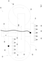
- the dosing units 50, 52 comprise respective movement control units 66, 68, each of which is configured for moving the respective nozzle support body 54, 56 along a closed-loop path 70.
- the closed-loop path 70 has a lower delivery section 72 extending in the machine direction MD and an upper return section 74.
- the two nozzle support bodies 54, 56 move independently of each other along the same closed-loop path 70.
- the orientation of the nozzles 58, 60 remains constant during the movement of the nozzle support bodies 54, 56 along the closed-loop path 70.
- the fluid delivery apertures of the nozzles 58, 60 may be oriented in a vertical direction or in an inclined direction oriented downwardly.
- the movement control units 66, 68 may adjust the vertical position which the fluid delivery apertures of the nozzles 58, 60 have during the movement of the nozzle support bodies 54, 56 along the closed-loop path 70, so as to adjust the distance between the fluid delivery apertures and the walls of the cavities 14.
- the adjustment of the vertical position of the fluid delivery apertures of the nozzles 58, 60 may be carried out when the type of fluid to be dispensed is changed, so as to adapt the distance between the fluid delivery apertures and the walls of the cavities 14 to the viscosity of the fluid. This adjustment is highly effective for eliminating splashing and can be carried out via software by the movement control units 66, 68, without the need of manual interventions.
- the two movement control units 66, 68 are located on opposite sides of a median vertical plane of the forming surface 12 and carry in cantilever fashion the respective nozzle support bodies 54, 56.
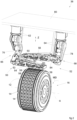
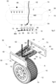
- Figures 2-6 show three possible embodiments of the movement control units 66, 68.
- the embodiments shown in figures 2-6 represent only non-limiting examples and many other design options are readily available for a skilled person.
- the movement control units 66, 68 comprise respective robotic arms 76, 78 having respective bases fixed to a stationary support 80 and respective terminal elements 82, 84 connected to respective nozzle support bodies 54, 56 and movable in at least two orthogonal directions, i.e. in the machine direction MD and in a vertical direction Z.
- the robotic arms 76, 78 are programmed to move the respective nozzle support bodies 54, 56 along the closed-loop path 70 in phase with the movement of the forming surface 12 in the machine direction MD, so that the nozzles 58, 60 are facing respective cavities 14 during the movement along the lower delivery section 72 of the closed-loop path 70.
- the nozzles 58, 60 are supplied with pressurized fluid during the movement along the lower delivery section 72. The supply of pressurized fluid stops when the nozzles 58, 60 reach the end of the lower delivery section 72 of the closed-loop path 70.
- the robotic arms 76, 78 may adjust the vertical position which the nozzles 58, 60 have when they travel along the lower delivery section 72 depending on the type of fluid delivered.
- the robotic arms 76, 78 may also automatically move the nozzle support bodies 54, 56 to a purge area for purging the nozzles 58, 60 when the delivered fluid must be changed. All the set-up operations necessary when changing the delivered fluid (e.g. purging and vertical adjustment of the nozzles) may be carried out automatically.
- each of the movement control units 66, 68 comprises a first linear guide 86 extending along the machine direction MD and a second linear guide 88 extending along a vertical direction Z.
- the second linear guide 88 is movable along the first linear guide 86 in the machine direction MD.
- the second linear guide 88 is also movable in the vertical direction Z with respect to the first linear guide 86.
- a lower end of the second linear guide 88 is connected to the respective nozzle support body 54.
- the movement of each nozzle support body 54, 56 may be controlled by a respective closed-loop belt 87 wound on two pulleys 89, one of which is driven by a motor 90.
- each nozzle support body 54, 56 may carry a plurality of transverse nozzle rows 96 and a plurality of actuators 98 arranged between each transverse nozzle row 96 and the nozzle support body 54.
- the actuators 98 control the vertical position Z of the respective transverse nozzle rows 96 with respect to the nozzle support body 54.
- the transverse nozzle rows 96 may move in the vertical direction independently of each other. This embodiment is useful in particular when the forming surface 12 is cylindrical. In fact, if the vertical position of the nozzles 58, 60 were constant, the distance between the fluid delivery apertures of the nozzles 58, 60 and the walls of the cavities 14 would vary during the movement of the nozzles 58, 60 in the machine direction MD.
- each transverse nozzle row 96 allows to maintain constant the distance between the fluid delivery apertures of the nozzles 58, 60 and the level of fluid contained in the cavities 14 during the movement of the nozzles 58, 60 in the machine direction MD.
- the movement control units 66, 68 comprise respective stationary guides 92, 93 extending along the closed-loop path 70 and respective movable elements 94, 95 movable along the respective stationary guides 92 along the closed-loop path 70 and connected to respective nozzle support bodies 54, 56.
- Each stationary guide 92, 93 and the associated movable element 94, 95 may be, respectively, the stator and the mover of a linear motor.
- the movable elements 94, 95 may be adjustable in the vertical direction Z to adjust the vertical position of the nozzles 58, 60.
- FIGS 7-10 schematically show the operation of the dosing apparatus 36.
- the second nozzle support body 56 moves in a direction opposite to the machine direction MD along the upper return section 74 of the closed-loop path 70.
- the nozzles 58 of the first nozzle support body 54 fill the respective recesses of the first continuous water-soluble film 20, placed at the respective cavities 14.
- the second nozzle support body 56 starts moving in the machine direction MD along the lower delivery section 72 and fills a new set of recesses.
- the movement of the nozzle support bodies 54, 56 along a closed-loop path 70 having a lower delivery section 72 and an upper return section 74 is effective for solving the problem of splashing in that the cyclical movement between a raised position and a lowered position allows the fluid delivery apertures of the nozzles 58, 60 to be positioned at a reduced distance from the walls of the cavities 14.
- the movement control units 66, 68 may be configured to control the angular position of the respective nozzle support bodies 54, 56 about a horizontal transverse axis during the movement of the respective nozzle support body 54, 56 along the lower delivery section 72 of the closed-loop path 70.
- the inclination of the nozzle support bodies 54, 56 about a horizontal transverse axis allows the nozzle support bodies 54, 56 to be oriented tangential to the forming surface 12 during the whole movement along the lower delivery section 72 of the closed-loop path 70.
- each of the nozzle support bodies 54, 56 may have a lower surface having the same curvature as that of the cylindrical forming surface 12 of the drum 16.
- the movement control units 66, 68 are controlled so as to keep the nozzles 58, 60 orthogonal to the respective cavities during the movement of the nozzle support bodies 54, 56 along the lower delivery section 72 of the closed-loop path 70.
- the movement control units 66, 68 may be configured to insert the fluid delivering apertures of the nozzles 58, 60 into respective cavities 14 during the movement of the nozzle support bodies 54, 56 along the lower delivery section 72 of the closed-loop path 70, so as to reduce the distance between the fluid delivery apertures of the nozzles 58, 60 and the walls of the cavities 14 during the dispensing step.
- This feature which is particularly effective in eliminating splashing, would not be possible in prior art solutions in which the nozzles are reciprocated along a straight horizontal direction.
Landscapes
- Engineering & Computer Science (AREA)
- Mechanical Engineering (AREA)
- Chemical & Material Sciences (AREA)
- Fluid Mechanics (AREA)
- Physics & Mathematics (AREA)
- Chemical Kinetics & Catalysis (AREA)
- Oil, Petroleum & Natural Gas (AREA)
- Wood Science & Technology (AREA)
- Organic Chemistry (AREA)
- Life Sciences & Earth Sciences (AREA)
- Coating Apparatus (AREA)
- Containers And Plastic Fillers For Packaging (AREA)
- Basic Packing Technique (AREA)
Claims (15)
- Appareil de dosage pour une machine de fabrication d'articles de dose unitaire, comprenant une première unité de dosage (50) et une seconde unité de dosage (52), chaque unité de dosage (50, 52) comprenant :- un corps de support de buse (54, 56),- une pluralité de buses (58, 60) ayant des ouvertures de distribution de fluide respectives, transportées par ledit corps de support de buse (54, 56) et reliées à un système de distribution de fluide par l'intermédiaire d'au moins un tube flexible (62, 64), et- une unité de commande de mouvement (66, 68) configurée pour déplacer le corps de support de buse respectif (54, 56) le long d'une trajectoire en boucle fermée (70) ayant une section de distribution inférieure (72) et une section de retour supérieure (74),les unités de commande de mouvement (66, 68) de la première et de la seconde unité de dosage (50, 52) étant configurées pour déplacer les corps de support de buse respectifs (54, 56) indépendamment l'un de l'autre le long de ladite trajectoire en boucle fermée (70).
- Appareil de dosage selon la revendication 1, chaque unité de commande de mouvement (66, 68) étant configurée pour ajuster la position dans une direction verticale que les ouvertures de distribution de fluide des buses respectives (58, 60) ont pendant le mouvement desdits corps de support de buse (54, 56) le long de ladite section de distribution inférieure (72, 74) de ladite trajectoire en boucle fermée (70).
- Appareil de dosage selon la revendication 1 ou 2, chaque corps de support de buse (54, 56) transportant une pluralité de rangées de buses transversales (96) et une pluralité d'actionneurs (98) agencés de manière à commander la position verticale de chaque rangée de buses transversales (96) par rapport au corps de support de buses respectif (54, 56).
- Appareil de dosage selon l'une quelconque des revendications 1 à 3, chaque unité de commande de mouvement (66, 68) comprenant un bras robotique (76, 78) ayant un élément terminal (82, 84) relié au corps de support de buse respectif (54, 56) et mobile dans au moins deux directions orthogonales (MD, Z).
- Appareil de dosage selon l'une quelconque des revendications 1 à 3, chaque unité de commande de mouvement (66, 68) comprenant un premier guide linéaire (86) s'étendant le long d'une première direction (MD), et un second guide linéaire (88) s'étendant le long d'une seconde direction (Z) orthogonale à ladite première direction (MD) et mobile par rapport audit premier guide linéaire (86) le long de ladite première direction (MD) et de ladite seconde direction (Z), une extrémité inférieure dudit second guide linéaire (88) étant reliée au corps de support de buse respectif (54, 56).
- Appareil de dosage selon l'une quelconque des revendications 1 à 3, chaque unité de commande de mouvement (66, 68) comprenant un guide stationnaire (92, 93) s'étendant le long de ladite trajectoire en boucle fermée (70) et un élément mobile (94, 95) pouvant se déplacer le long dudit guide stationnaire (92, 93) et relié au corps de support de buse respectif (54, 56).
- Machine de fabrication d'articles de dose unitaire, comprenant :- une surface de formation (12) ayant une pluralité de cavités (14), pouvant se déplacer en continu dans la direction de la machine (MD),- un premier ensemble d'alimentation (18) configuré pour alimenter par un premier film hydrosoluble continu (20) ladite surface de formation (12) au niveau d'une première position (24),- un système de retenue (26) configuré pour retenir ledit premier film continu hydrosoluble (20) adhérant auxdites cavités (14) lors de son déplacement dans ladite direction de machine (MD),- un appareil de dosage (36) selon l'une quelconque des revendications précédentes, situé en aval de ladite première position (24) et configuré pour distribuer des quantités dosées d'au moins une composition fluide dans lesdites cavités (14),- un second ensemble d'alimentation (28) configuré pour alimenter par un second film continu hydrosoluble (30) ladite surface de formation (12) au niveau d'une seconde position (32) située en aval de ladite unité de dosage (36) de manière à enfermer lesdites quantités dosées d'au moins une composition fluide entre lesdits premier et second films continus hydrosolubles (20, 30), et- une unité de mouillage (38) configurée pour mouiller une surface dudit second film continu hydrosoluble (30) en amont de ladite seconde position (32).
- Machine selon la revendication 7, ladite surface de formation (12) étant une surface extérieure cylindrique d'un tambour (16) tournant autour d'un axe horizontal (A).
- Machine selon la revendication 8, chacun desdits corps de support de buse (54, 56) ayant une surface inférieure ayant la même courbure que celle de ladite surface de formation cylindrique (12).
- Machine selon la revendication 7, ladite surface de formation (12) étant la surface extérieure d'une courroie en boucle fermée ayant une section supérieure horizontale et une section de retour inférieure, ladite section supérieure horizontale de ladite courroie en boucle fermée étant orientée vers ladite section de distribution inférieure (72) de ladite trajectoire en boucle fermée (70).
- Machine selon l'une quelconque des revendications 7 à 10, lesdites unités de commande de mouvement (66, 68) étant configurées pour déplacer automatiquement les corps de support de buse respectifs (54, 56) vers une zone de purge éloignée de ladite surface de formation (12) pour purger les buses (58, 60) lorsque le fluide distribué doit être changé.
- Procédé de production d'articles à dose unitaire, comprenant :- la fourniture d'une surface de formation (12) ayant une pluralité de cavités (14), pouvant se déplacer en continu dans une direction de machine (MD),- l'alimentation par un premier film hydrosoluble continu (20) de ladite surface de formation (12) au niveau d'une première position (24),- la retenue dudit premier film hydrosoluble continu (20) sur ladite surface de formation (12) lors de son déplacement dans ladite direction de machine (MD) et la formation dans ledit premier film hydrosoluble continu (20) d'une pluralité d'évidements en maintenant le premier film hydrosoluble continu (20) adhérent auxdites cavités (14),- la fourniture d'un premier corps de support de buse (54) et d'un second corps de support de buse (56) transportant des buses respectives (58, 60) ayant des ouvertures de distribution de fluide respectives et reliées à un système de distribution de fluide par l'intermédiaire de tubes flexibles respectifs (62, 64),- le déplacement de manière continue dudit premier corps de support de buse (54) et du second corps de support de buse (56) indépendamment l'un de l'autre le long d'une trajectoire en boucle fermée (70) ayant une section de distribution inférieure (72) et une section de retour supérieure (74),- l'administration de quantités dosées de produits fluides dans lesdits évidements à travers lesdites buses (58, 60) pendant le mouvement dudit premier corps de support de buse (54) et du second corps de support de buse (56) le long de ladite section de distribution inférieure (72) de ladite trajectoire en boucle fermée (70), et- l'application d'un second film hydrosoluble continu (30) sur ledit premier film hydrosoluble (20) et la liaison l'un à l'autre desdits premier et second films hydrosolubles (20, 22) par étanchéification autour desdits évidements de manière à enfermer lesdites quantités dosées de composition fluide entre lesdits premier et second films hydrosolubles continus (20, 30).
- Procédé selon la revendication 12, comprenant le déplacement de l'un dudit premiers corps de support de buse (54) et dudit second corps de support de buse (56) dans ladite direction de machine (MD) le long de la section de distribution inférieure (72) de la trajectoire en boucle fermée (70) tout en déplaçant l'autre dudit premier corps de support de buse (54) et dudit second corps de support de buse (56) dans une direction opposée à ladite direction de machine (MD) le long de la section de retour supérieure (72) de la trajectoire en boucle fermée (70).
- Procédé selon la revendication 12 ou 13, comprenant l'insertion des ouvertures de distribution de fluide desdites buses (58, 60) dans des évidements respectifs pendant le mouvement dudit premier corps de support de buse (54) et dudit second corps de support de buse (56) le long de ladite section de distribution inférieure (72) de ladite trajectoire en boucle fermée (70).
- Procédé selon l'une quelconque des revendications 12 à 14, comprenant l'ajustement de la position dans une direction verticale que lesdites ouvertures de distribution de fluide ont pendant le mouvement dudit premier corps de support de buse (54) et dudit second corps de support de buse (56) le long de ladite section de distribution inférieure (72, 74) de ladite trajectoire en boucle fermée (70).
Priority Applications (5)
| Application Number | Priority Date | Filing Date | Title |
|---|---|---|---|
| PL21169203.3T PL4079649T3 (pl) | 2021-04-19 | 2021-04-19 | Aparat dozujący oraz maszyna i sposób do wytwarzania artykułów z dawką jednostkową |
| ES21169203T ES2970338T3 (es) | 2021-04-19 | 2021-04-19 | Un aparato de dosificación, y máquina y procedimiento para producir artículos de dosis unitaria |
| EP21169203.3A EP4079649B1 (fr) | 2021-04-19 | 2021-04-19 | Appareil de dosage et machine et procédé de fabrication d'articles de dose unitaire |
| US17/722,695 US12110144B2 (en) | 2021-04-19 | 2022-04-18 | Dosing apparatus, and machine and method for producing unit dose articles |
| CN202210402972.8A CN115214914B (zh) | 2021-04-19 | 2022-04-18 | 用于生产单位用量制品的定量配给设备、机器和方法 |
Applications Claiming Priority (1)
| Application Number | Priority Date | Filing Date | Title |
|---|---|---|---|
| EP21169203.3A EP4079649B1 (fr) | 2021-04-19 | 2021-04-19 | Appareil de dosage et machine et procédé de fabrication d'articles de dose unitaire |
Publications (2)
| Publication Number | Publication Date |
|---|---|
| EP4079649A1 EP4079649A1 (fr) | 2022-10-26 |
| EP4079649B1 true EP4079649B1 (fr) | 2023-12-27 |
Family
ID=75639661
Family Applications (1)
| Application Number | Title | Priority Date | Filing Date |
|---|---|---|---|
| EP21169203.3A Active EP4079649B1 (fr) | 2021-04-19 | 2021-04-19 | Appareil de dosage et machine et procédé de fabrication d'articles de dose unitaire |
Country Status (5)
| Country | Link |
|---|---|
| US (1) | US12110144B2 (fr) |
| EP (1) | EP4079649B1 (fr) |
| CN (1) | CN115214914B (fr) |
| ES (1) | ES2970338T3 (fr) |
| PL (1) | PL4079649T3 (fr) |
Families Citing this family (3)
| Publication number | Priority date | Publication date | Assignee | Title |
|---|---|---|---|---|
| EP4071060A1 (fr) * | 2021-04-07 | 2022-10-12 | Fameccanica.Data S.p.A. | Unité de dosage, procédé de dosage et machine de production d'articles de dose unitaire |
| EP4071059A1 (fr) * | 2021-04-07 | 2022-10-12 | Fameccanica.Data S.p.A. | Unité de dosage, procédé de dosage, et machine de production d'articles de dose unique |
| CN116215999B (zh) * | 2023-01-28 | 2026-03-17 | 佛山市博维环保材料有限公司 | 小主辊敷水部件及水溶性薄膜包装机 |
Family Cites Families (24)
| Publication number | Priority date | Publication date | Assignee | Title |
|---|---|---|---|---|
| GB1036671A (en) * | 1963-04-25 | 1966-07-20 | H J Heinz Company Ltd | Improvements in or relating to apparatus for successively introducing flowable material into containers |
| US4571924A (en) * | 1985-04-29 | 1986-02-25 | The Procter & Gamble Company | Method and apparatus of manufacturing porous pouches containing granular product |
| GB8824925D0 (en) * | 1988-10-25 | 1988-11-30 | Bowater Packaging Ltd | Aseptic filling apparatus |
| AU4656989A (en) * | 1988-11-14 | 1990-06-12 | Oden Corporation | Precision filling machine |
| US5971041A (en) * | 1998-06-22 | 1999-10-26 | Kalish Canada Inc. | Container filling apparatus with walking nozzles bank |
| DE10246061B4 (de) * | 2002-10-02 | 2012-09-06 | Robert Bosch Gmbh | Verfahren zum Befüllen von pharmazeutischen Behältnissen wie Ampullen, Vials o.ä. |
| US6889739B2 (en) * | 2003-04-08 | 2005-05-10 | Automated Packaging Systems, Inc. | Fluid filled unit formation machine and process |
| GB0700925D0 (en) * | 2007-01-18 | 2007-02-28 | Reckitt Benckiser Nv | Dosage element and a method of manufacturing a dosage element |
| ITBO20070303A1 (it) * | 2007-04-24 | 2008-10-25 | Aroma System Srl Gino | Macchina per il confezionamento di capsule anche sotto vuoto e/o in atmosfera controllata |
| PL2380966T5 (pl) * | 2008-02-08 | 2022-05-30 | The Procter And Gamble Company | Sposób wytwarzania rozpuszczalnej w wodzie saszetki |
| GB2475538B (en) * | 2009-11-23 | 2011-11-23 | Rideau Machinery Inc | Improvements to continuous motion rotary thermoforming of soluble pouches |
| GB2520306B (en) * | 2013-11-15 | 2015-10-21 | Rideau Machinery Inc | Improvements to rotatable forming and filling of water-soluble pouches |
| EP3025969B1 (fr) * | 2013-04-19 | 2017-04-19 | Rideau Machinery Inc. | Sachets solubles dans l'eau |
| ES2447315B1 (es) * | 2013-07-30 | 2014-09-10 | Grifols Worldwide Operations Limited | Máquina y procedimiento para el llenado de contenedores de productos farmacéuticos |
| WO2015059101A1 (fr) * | 2013-10-21 | 2015-04-30 | Discma Ag | Machine permettant de former et de remplir des contenants comprenant une première boucle fermée et une seconde boucle fermée présentant une partie commune |
| CN106163928A (zh) | 2014-05-21 | 2016-11-23 | 宝洁公司 | 用于分配组合物的方法和系统 |
| CA2871901C (fr) * | 2014-10-24 | 2021-07-20 | Multi-Pack Solutions | Systemes et methodes de formation de paquets hydrosolubles a double couche |
| US11225348B2 (en) * | 2015-05-22 | 2022-01-18 | The Procter & Gamble Company | Process of making a water soluble pouch |
| GB201516903D0 (en) * | 2015-09-24 | 2015-11-11 | Rideau Machinery Inc | Moving filling nozzles on a rotatable forming machine |
| US20170088298A1 (en) * | 2015-09-25 | 2017-03-30 | Multi-Pack Solutions, LLC | Packaging machine with independently controllable movers |
| US9862585B2 (en) * | 2016-05-27 | 2018-01-09 | Psr Automation, Inc. | Continuous motion linear container filler |
| IT201600126510A1 (it) * | 2016-12-15 | 2018-06-15 | Corazza S P A | Macchina e procedimento per realizzare confezioni contenenti prodotti liquidi o pastosi. |
| NL2018707B1 (en) * | 2017-04-13 | 2018-10-24 | Eme Engel Machf En Engineering B V | Packaging system for producing pouches |
| LU100315B1 (en) * | 2017-06-14 | 2018-12-18 | Soremartec Sa | Dropper Machine |
-
2021
- 2021-04-19 EP EP21169203.3A patent/EP4079649B1/fr active Active
- 2021-04-19 ES ES21169203T patent/ES2970338T3/es active Active
- 2021-04-19 PL PL21169203.3T patent/PL4079649T3/pl unknown
-
2022
- 2022-04-18 CN CN202210402972.8A patent/CN115214914B/zh active Active
- 2022-04-18 US US17/722,695 patent/US12110144B2/en active Active
Also Published As
| Publication number | Publication date |
|---|---|
| US12110144B2 (en) | 2024-10-08 |
| CN115214914B (zh) | 2023-11-14 |
| ES2970338T3 (es) | 2024-05-28 |
| PL4079649T3 (pl) | 2024-03-25 |
| US20220332452A1 (en) | 2022-10-20 |
| CN115214914A (zh) | 2022-10-21 |
| EP4079649A1 (fr) | 2022-10-26 |
Similar Documents
| Publication | Publication Date | Title |
|---|---|---|
| US12110144B2 (en) | Dosing apparatus, and machine and method for producing unit dose articles | |
| US6769231B2 (en) | Apparatus, method and flexible bag for use in manufacturing | |
| EP2819923B1 (fr) | Appareil de formation de paquets et système de remplissage | |
| US6966166B2 (en) | High-speed continuous action form-fill-seal machine and methods | |
| EP3642007B1 (fr) | Appareil et procede de formation de sachets hydrosolubles | |
| WO2017051392A1 (fr) | Déplacement de buses de remplissage sur une machine de formation rotative | |
| WO2013130466A1 (fr) | Procédé de fabrication de conditionnements | |
| EP3913334B1 (fr) | Système de dosage de liquide | |
| US11628956B2 (en) | Dosing unit, a dosing method, and a machine for producing unit dose articles | |
| US11634245B2 (en) | Dosing unit, a dosing method, and a machine for producing unit dose articles | |
| EP1755955B1 (fr) | Procede et appareil de fabrication d'emballages de produits | |
| EP4190707A1 (fr) | Unité de mouillage et machine de formage et procédé de fabrication d'articles de dose unitaire | |
| US20160362200A1 (en) | Process and apparatus for making water soluble pouches | |
| CN117068493A (zh) | 多列条状袋包装机灌装结构及灌装方法 | |
| HK1201799B (en) | Apparatus for forming packages and filling system |
Legal Events
| Date | Code | Title | Description |
|---|---|---|---|
| PUAI | Public reference made under article 153(3) epc to a published international application that has entered the european phase |
Free format text: ORIGINAL CODE: 0009012 |
|
| STAA | Information on the status of an ep patent application or granted ep patent |
Free format text: STATUS: THE APPLICATION HAS BEEN PUBLISHED |
|
| AK | Designated contracting states |
Kind code of ref document: A1 Designated state(s): AL AT BE BG CH CY CZ DE DK EE ES FI FR GB GR HR HU IE IS IT LI LT LU LV MC MK MT NL NO PL PT RO RS SE SI SK SM TR |
|
| STAA | Information on the status of an ep patent application or granted ep patent |
Free format text: STATUS: REQUEST FOR EXAMINATION WAS MADE |
|
| 17P | Request for examination filed |
Effective date: 20230126 |
|
| RBV | Designated contracting states (corrected) |
Designated state(s): AL AT BE BG CH CY CZ DE DK EE ES FI FR GB GR HR HU IE IS IT LI LT LU LV MC MK MT NL NO PL PT RO RS SE SI SK SM TR |
|
| RIC1 | Information provided on ipc code assigned before grant |
Ipc: B65B 3/02 20060101ALI20230614BHEP Ipc: B65B 9/04 20060101ALI20230614BHEP Ipc: B65B 47/02 20060101ALI20230614BHEP Ipc: B65B 39/14 20060101ALI20230614BHEP Ipc: B65B 39/12 20060101AFI20230614BHEP |
|
| GRAP | Despatch of communication of intention to grant a patent |
Free format text: ORIGINAL CODE: EPIDOSNIGR1 |
|
| STAA | Information on the status of an ep patent application or granted ep patent |
Free format text: STATUS: GRANT OF PATENT IS INTENDED |
|
| INTG | Intention to grant announced |
Effective date: 20230801 |
|
| GRAS | Grant fee paid |
Free format text: ORIGINAL CODE: EPIDOSNIGR3 |
|
| GRAA | (expected) grant |
Free format text: ORIGINAL CODE: 0009210 |
|
| STAA | Information on the status of an ep patent application or granted ep patent |
Free format text: STATUS: THE PATENT HAS BEEN GRANTED |
|
| AK | Designated contracting states |
Kind code of ref document: B1 Designated state(s): AL AT BE BG CH CY CZ DE DK EE ES FI FR GB GR HR HU IE IS IT LI LT LU LV MC MK MT NL NO PL PT RO RS SE SI SK SM TR |
|
| REG | Reference to a national code |
Ref country code: GB Ref legal event code: FG4D |
|
| REG | Reference to a national code |
Ref country code: CH Ref legal event code: EP |
|
| REG | Reference to a national code |
Ref country code: DE Ref legal event code: R096 Ref document number: 602021007999 Country of ref document: DE |
|
| REG | Reference to a national code |
Ref country code: IE Ref legal event code: FG4D |
|
| REG | Reference to a national code |
Ref country code: NL Ref legal event code: FP |
|
| REG | Reference to a national code |
Ref country code: SE Ref legal event code: TRGR |
|
| PG25 | Lapsed in a contracting state [announced via postgrant information from national office to epo] |
Ref country code: GR Free format text: LAPSE BECAUSE OF FAILURE TO SUBMIT A TRANSLATION OF THE DESCRIPTION OR TO PAY THE FEE WITHIN THE PRESCRIBED TIME-LIMIT Effective date: 20240328 |
|
| REG | Reference to a national code |
Ref country code: LT Ref legal event code: MG9D |
|
| PG25 | Lapsed in a contracting state [announced via postgrant information from national office to epo] |
Ref country code: LT Free format text: LAPSE BECAUSE OF FAILURE TO SUBMIT A TRANSLATION OF THE DESCRIPTION OR TO PAY THE FEE WITHIN THE PRESCRIBED TIME-LIMIT Effective date: 20231227 |
|
| PG25 | Lapsed in a contracting state [announced via postgrant information from national office to epo] |
Ref country code: LT Free format text: LAPSE BECAUSE OF FAILURE TO SUBMIT A TRANSLATION OF THE DESCRIPTION OR TO PAY THE FEE WITHIN THE PRESCRIBED TIME-LIMIT Effective date: 20231227 Ref country code: GR Free format text: LAPSE BECAUSE OF FAILURE TO SUBMIT A TRANSLATION OF THE DESCRIPTION OR TO PAY THE FEE WITHIN THE PRESCRIBED TIME-LIMIT Effective date: 20240328 Ref country code: FI Free format text: LAPSE BECAUSE OF FAILURE TO SUBMIT A TRANSLATION OF THE DESCRIPTION OR TO PAY THE FEE WITHIN THE PRESCRIBED TIME-LIMIT Effective date: 20231227 Ref country code: BG Free format text: LAPSE BECAUSE OF FAILURE TO SUBMIT A TRANSLATION OF THE DESCRIPTION OR TO PAY THE FEE WITHIN THE PRESCRIBED TIME-LIMIT Effective date: 20240327 |
|
| REG | Reference to a national code |
Ref country code: ES Ref legal event code: FG2A Ref document number: 2970338 Country of ref document: ES Kind code of ref document: T3 Effective date: 20240528 |
|
| PG25 | Lapsed in a contracting state [announced via postgrant information from national office to epo] |
Ref country code: RS Free format text: LAPSE BECAUSE OF FAILURE TO SUBMIT A TRANSLATION OF THE DESCRIPTION OR TO PAY THE FEE WITHIN THE PRESCRIBED TIME-LIMIT Effective date: 20231227 Ref country code: NO Free format text: LAPSE BECAUSE OF FAILURE TO SUBMIT A TRANSLATION OF THE DESCRIPTION OR TO PAY THE FEE WITHIN THE PRESCRIBED TIME-LIMIT Effective date: 20240327 Ref country code: LV Free format text: LAPSE BECAUSE OF FAILURE TO SUBMIT A TRANSLATION OF THE DESCRIPTION OR TO PAY THE FEE WITHIN THE PRESCRIBED TIME-LIMIT Effective date: 20231227 Ref country code: HR Free format text: LAPSE BECAUSE OF FAILURE TO SUBMIT A TRANSLATION OF THE DESCRIPTION OR TO PAY THE FEE WITHIN THE PRESCRIBED TIME-LIMIT Effective date: 20231227 |
|
| PG25 | Lapsed in a contracting state [announced via postgrant information from national office to epo] |
Ref country code: IS Free format text: LAPSE BECAUSE OF FAILURE TO SUBMIT A TRANSLATION OF THE DESCRIPTION OR TO PAY THE FEE WITHIN THE PRESCRIBED TIME-LIMIT Effective date: 20240427 |
|
| PG25 | Lapsed in a contracting state [announced via postgrant information from national office to epo] |
Ref country code: SK Free format text: LAPSE BECAUSE OF FAILURE TO SUBMIT A TRANSLATION OF THE DESCRIPTION OR TO PAY THE FEE WITHIN THE PRESCRIBED TIME-LIMIT Effective date: 20231227 |
|
| PG25 | Lapsed in a contracting state [announced via postgrant information from national office to epo] |
Ref country code: SM Free format text: LAPSE BECAUSE OF FAILURE TO SUBMIT A TRANSLATION OF THE DESCRIPTION OR TO PAY THE FEE WITHIN THE PRESCRIBED TIME-LIMIT Effective date: 20231227 Ref country code: SK Free format text: LAPSE BECAUSE OF FAILURE TO SUBMIT A TRANSLATION OF THE DESCRIPTION OR TO PAY THE FEE WITHIN THE PRESCRIBED TIME-LIMIT Effective date: 20231227 Ref country code: RO Free format text: LAPSE BECAUSE OF FAILURE TO SUBMIT A TRANSLATION OF THE DESCRIPTION OR TO PAY THE FEE WITHIN THE PRESCRIBED TIME-LIMIT Effective date: 20231227 Ref country code: IS Free format text: LAPSE BECAUSE OF FAILURE TO SUBMIT A TRANSLATION OF THE DESCRIPTION OR TO PAY THE FEE WITHIN THE PRESCRIBED TIME-LIMIT Effective date: 20240427 Ref country code: EE Free format text: LAPSE BECAUSE OF FAILURE TO SUBMIT A TRANSLATION OF THE DESCRIPTION OR TO PAY THE FEE WITHIN THE PRESCRIBED TIME-LIMIT Effective date: 20231227 |
|
| PG25 | Lapsed in a contracting state [announced via postgrant information from national office to epo] |
Ref country code: PT Free format text: LAPSE BECAUSE OF FAILURE TO SUBMIT A TRANSLATION OF THE DESCRIPTION OR TO PAY THE FEE WITHIN THE PRESCRIBED TIME-LIMIT Effective date: 20240429 |
|
| PG25 | Lapsed in a contracting state [announced via postgrant information from national office to epo] |
Ref country code: PT Free format text: LAPSE BECAUSE OF FAILURE TO SUBMIT A TRANSLATION OF THE DESCRIPTION OR TO PAY THE FEE WITHIN THE PRESCRIBED TIME-LIMIT Effective date: 20240429 |
|
| REG | Reference to a national code |
Ref country code: AT Ref legal event code: UEP Ref document number: 1644325 Country of ref document: AT Kind code of ref document: T Effective date: 20231227 |
|
| REG | Reference to a national code |
Ref country code: DE Ref legal event code: R097 Ref document number: 602021007999 Country of ref document: DE |
|
| PG25 | Lapsed in a contracting state [announced via postgrant information from national office to epo] |
Ref country code: DK Free format text: LAPSE BECAUSE OF FAILURE TO SUBMIT A TRANSLATION OF THE DESCRIPTION OR TO PAY THE FEE WITHIN THE PRESCRIBED TIME-LIMIT Effective date: 20231227 |
|
| PG25 | Lapsed in a contracting state [announced via postgrant information from national office to epo] |
Ref country code: DK Free format text: LAPSE BECAUSE OF FAILURE TO SUBMIT A TRANSLATION OF THE DESCRIPTION OR TO PAY THE FEE WITHIN THE PRESCRIBED TIME-LIMIT Effective date: 20231227 |
|
| PLBE | No opposition filed within time limit |
Free format text: ORIGINAL CODE: 0009261 |
|
| STAA | Information on the status of an ep patent application or granted ep patent |
Free format text: STATUS: NO OPPOSITION FILED WITHIN TIME LIMIT |
|
| PG25 | Lapsed in a contracting state [announced via postgrant information from national office to epo] |
Ref country code: MC Free format text: LAPSE BECAUSE OF FAILURE TO SUBMIT A TRANSLATION OF THE DESCRIPTION OR TO PAY THE FEE WITHIN THE PRESCRIBED TIME-LIMIT Effective date: 20231227 |
|
| PG25 | Lapsed in a contracting state [announced via postgrant information from national office to epo] |
Ref country code: MC Free format text: LAPSE BECAUSE OF FAILURE TO SUBMIT A TRANSLATION OF THE DESCRIPTION OR TO PAY THE FEE WITHIN THE PRESCRIBED TIME-LIMIT Effective date: 20231227 |
|
| 26N | No opposition filed |
Effective date: 20240930 |
|
| PG25 | Lapsed in a contracting state [announced via postgrant information from national office to epo] |
Ref country code: LU Free format text: LAPSE BECAUSE OF NON-PAYMENT OF DUE FEES Effective date: 20240419 |
|
| PG25 | Lapsed in a contracting state [announced via postgrant information from national office to epo] |
Ref country code: LU Free format text: LAPSE BECAUSE OF NON-PAYMENT OF DUE FEES Effective date: 20240419 |
|
| PG25 | Lapsed in a contracting state [announced via postgrant information from national office to epo] |
Ref country code: IE Free format text: LAPSE BECAUSE OF NON-PAYMENT OF DUE FEES Effective date: 20240419 |
|
| PG25 | Lapsed in a contracting state [announced via postgrant information from national office to epo] |
Ref country code: SI Free format text: LAPSE BECAUSE OF FAILURE TO SUBMIT A TRANSLATION OF THE DESCRIPTION OR TO PAY THE FEE WITHIN THE PRESCRIBED TIME-LIMIT Effective date: 20231227 |
|
| PGFP | Annual fee paid to national office [announced via postgrant information from national office to epo] |
Ref country code: NL Payment date: 20250427 Year of fee payment: 5 |
|
| PGFP | Annual fee paid to national office [announced via postgrant information from national office to epo] |
Ref country code: PL Payment date: 20250401 Year of fee payment: 5 Ref country code: DE Payment date: 20250429 Year of fee payment: 5 |
|
| PGFP | Annual fee paid to national office [announced via postgrant information from national office to epo] |
Ref country code: GB Payment date: 20250428 Year of fee payment: 5 Ref country code: ES Payment date: 20250505 Year of fee payment: 5 |
|
| PGFP | Annual fee paid to national office [announced via postgrant information from national office to epo] |
Ref country code: BE Payment date: 20250428 Year of fee payment: 5 Ref country code: IT Payment date: 20250422 Year of fee payment: 5 |
|
| PGFP | Annual fee paid to national office [announced via postgrant information from national office to epo] |
Ref country code: FR Payment date: 20250425 Year of fee payment: 5 |
|
| PGFP | Annual fee paid to national office [announced via postgrant information from national office to epo] |
Ref country code: CH Payment date: 20250501 Year of fee payment: 5 |
|
| PGFP | Annual fee paid to national office [announced via postgrant information from national office to epo] |
Ref country code: AT Payment date: 20250721 Year of fee payment: 5 |
|
| PGFP | Annual fee paid to national office [announced via postgrant information from national office to epo] |
Ref country code: TR Payment date: 20250418 Year of fee payment: 5 |
|
| PGFP | Annual fee paid to national office [announced via postgrant information from national office to epo] |
Ref country code: CZ Payment date: 20250407 Year of fee payment: 5 |
|
| PGFP | Annual fee paid to national office [announced via postgrant information from national office to epo] |
Ref country code: SE Payment date: 20250430 Year of fee payment: 5 |
|
| PG25 | Lapsed in a contracting state [announced via postgrant information from national office to epo] |
Ref country code: CY Free format text: LAPSE BECAUSE OF FAILURE TO SUBMIT A TRANSLATION OF THE DESCRIPTION OR TO PAY THE FEE WITHIN THE PRESCRIBED TIME-LIMIT; INVALID AB INITIO Effective date: 20210419 |
|
| PG25 | Lapsed in a contracting state [announced via postgrant information from national office to epo] |
Ref country code: HU Free format text: LAPSE BECAUSE OF FAILURE TO SUBMIT A TRANSLATION OF THE DESCRIPTION OR TO PAY THE FEE WITHIN THE PRESCRIBED TIME-LIMIT; INVALID AB INITIO Effective date: 20210419 |
|
| REG | Reference to a national code |
Ref country code: CH Ref legal event code: U11 Free format text: ST27 STATUS EVENT CODE: U-0-0-U10-U11 (AS PROVIDED BY THE NATIONAL OFFICE) Effective date: 20260501 |