EP4079667B1 - Verfahren zur herstellung von kernlosen papierrollen und eine klammer - Google Patents
Verfahren zur herstellung von kernlosen papierrollen und eine klammer Download PDFInfo
- Publication number
- EP4079667B1 EP4079667B1 EP22161866.3A EP22161866A EP4079667B1 EP 4079667 B1 EP4079667 B1 EP 4079667B1 EP 22161866 A EP22161866 A EP 22161866A EP 4079667 B1 EP4079667 B1 EP 4079667B1
- Authority
- EP
- European Patent Office
- Prior art keywords
- mandrel
- log
- mandrels
- elastic
- yield strength
- Prior art date
- Legal status (The legal status is an assumption and is not a legal conclusion. Google has not performed a legal analysis and makes no representation as to the accuracy of the status listed.)
- Active
Links
Images


Classifications
-
- B—PERFORMING OPERATIONS; TRANSPORTING
- B65—CONVEYING; PACKING; STORING; HANDLING THIN OR FILAMENTARY MATERIAL
- B65H—HANDLING THIN OR FILAMENTARY MATERIAL, e.g. SHEETS, WEBS, CABLES
- B65H19/00—Changing the web roll
- B65H19/22—Changing the web roll in winding mechanisms or in connection with winding operations
- B65H19/2292—Removing cores or mandrels from web roll after winding
-
- B—PERFORMING OPERATIONS; TRANSPORTING
- B65—CONVEYING; PACKING; STORING; HANDLING THIN OR FILAMENTARY MATERIAL
- B65H—HANDLING THIN OR FILAMENTARY MATERIAL, e.g. SHEETS, WEBS, CABLES
- B65H18/00—Winding webs
- B65H18/02—Supporting web roll
- B65H18/04—Interior-supporting
-
- B—PERFORMING OPERATIONS; TRANSPORTING
- B65—CONVEYING; PACKING; STORING; HANDLING THIN OR FILAMENTARY MATERIAL
- B65H—HANDLING THIN OR FILAMENTARY MATERIAL, e.g. SHEETS, WEBS, CABLES
- B65H18/00—Winding webs
- B65H18/28—Wound package of webs
-
- B—PERFORMING OPERATIONS; TRANSPORTING
- B65—CONVEYING; PACKING; STORING; HANDLING THIN OR FILAMENTARY MATERIAL
- B65H—HANDLING THIN OR FILAMENTARY MATERIAL, e.g. SHEETS, WEBS, CABLES
- B65H19/00—Changing the web roll
- B65H19/22—Changing the web roll in winding mechanisms or in connection with winding operations
- B65H19/28—Attaching the leading end of the web to the replacement web-roll core or spindle
- B65H19/283—Attaching the leading end of the web to the replacement web-roll core or spindle by applying adhesive to the core
-
- B—PERFORMING OPERATIONS; TRANSPORTING
- B65—CONVEYING; PACKING; STORING; HANDLING THIN OR FILAMENTARY MATERIAL
- B65H—HANDLING THIN OR FILAMENTARY MATERIAL, e.g. SHEETS, WEBS, CABLES
- B65H75/00—Storing webs, tapes, or filamentary material, e.g. on reels
- B65H75/02—Cores, formers, supports, or holders for coiled, wound, or folded material, e.g. reels, spindles, bobbins, cop tubes, cans, mandrels or chucks
- B65H75/18—Constructional details
- B65H75/24—Constructional details adjustable in configuration, e.g. expansible
- B65H75/242—Expansible spindles, mandrels or chucks, e.g. for securing or releasing cores, holders or packages
- B65H75/245—Expansible spindles, mandrels or chucks, e.g. for securing or releasing cores, holders or packages by deformation of an elastic or flexible material
- B65H75/2455—Expansible spindles, mandrels or chucks, e.g. for securing or releasing cores, holders or packages by deformation of an elastic or flexible material deformation resulting from axial compression of elastic or flexible material
-
- B—PERFORMING OPERATIONS; TRANSPORTING
- B65—CONVEYING; PACKING; STORING; HANDLING THIN OR FILAMENTARY MATERIAL
- B65H—HANDLING THIN OR FILAMENTARY MATERIAL, e.g. SHEETS, WEBS, CABLES
- B65H2301/00—Handling processes for sheets or webs
- B65H2301/40—Type of handling process
- B65H2301/41—Winding, unwinding
- B65H2301/417—Handling or changing web rolls
- B65H2301/418—Changing web roll
- B65H2301/4185—Core or mandrel discharge or removal, also organisation of core removal
- B65H2301/41852—Core or mandrel discharge or removal, also organisation of core removal by extracting mandrel from wound roll, e.g. in coreless applications
- B65H2301/418526—Core or mandrel discharge or removal, also organisation of core removal by extracting mandrel from wound roll, e.g. in coreless applications by movement of the mandrel
-
- B—PERFORMING OPERATIONS; TRANSPORTING
- B65—CONVEYING; PACKING; STORING; HANDLING THIN OR FILAMENTARY MATERIAL
- B65H—HANDLING THIN OR FILAMENTARY MATERIAL, e.g. SHEETS, WEBS, CABLES
- B65H2301/00—Handling processes for sheets or webs
- B65H2301/40—Type of handling process
- B65H2301/41—Winding, unwinding
- B65H2301/417—Handling or changing web rolls
- B65H2301/418—Changing web roll
- B65H2301/4185—Core or mandrel discharge or removal, also organisation of core removal
- B65H2301/41854—Core or mandrel discharge or removal, also organisation of core removal by extracting core from wound roll, i.e. in coreless applications only
-
- B—PERFORMING OPERATIONS; TRANSPORTING
- B65—CONVEYING; PACKING; STORING; HANDLING THIN OR FILAMENTARY MATERIAL
- B65H—HANDLING THIN OR FILAMENTARY MATERIAL, e.g. SHEETS, WEBS, CABLES
- B65H2405/00—Parts for holding the handled material
- B65H2405/40—Holders, supports for rolls
- B65H2405/46—Grippers for bobbins, i.e. rolls
- B65H2405/461—Grippers for bobbins, i.e. rolls center gripper (inside the core)
-
- B—PERFORMING OPERATIONS; TRANSPORTING
- B65—CONVEYING; PACKING; STORING; HANDLING THIN OR FILAMENTARY MATERIAL
- B65H—HANDLING THIN OR FILAMENTARY MATERIAL, e.g. SHEETS, WEBS, CABLES
- B65H2405/00—Parts for holding the handled material
- B65H2405/50—Gripping means
- B65H2405/57—Details of the gripping parts
- B65H2405/572—Retractable parts
-
- B—PERFORMING OPERATIONS; TRANSPORTING
- B65—CONVEYING; PACKING; STORING; HANDLING THIN OR FILAMENTARY MATERIAL
- B65H—HANDLING THIN OR FILAMENTARY MATERIAL, e.g. SHEETS, WEBS, CABLES
- B65H2511/00—Dimensions; Position; Numbers; Identification; Occurrences
- B65H2511/10—Size; Dimensions
- B65H2511/17—Deformation, e.g. stretching
-
- B—PERFORMING OPERATIONS; TRANSPORTING
- B65—CONVEYING; PACKING; STORING; HANDLING THIN OR FILAMENTARY MATERIAL
- B65H—HANDLING THIN OR FILAMENTARY MATERIAL, e.g. SHEETS, WEBS, CABLES
- B65H2701/00—Handled material; Storage means
- B65H2701/10—Handled articles or webs
- B65H2701/19—Specific article or web
- B65H2701/1924—Napkins or tissues, e.g. dressings, toweling, serviettes, kitchen paper and compresses
Definitions
- This invention relates to rolls of convolutely wound paper, such as bathroom tissue and kitchen towel (also called household towel). More particularly, the invention relates to a coreless roll of such paper.
- a rewinder is used to convert large parent rolls of paper into smaller sized rolls of bathroom tissue, kitchen towel, hardwound towel, industrial products, and the like.
- a rewinder line consists of one or more unwinds, modules for paper finishing (e.g., embossing, printing, perforating), and a rewinder at the end for winding the paper into a long roll, commonly referred to as a log.
- the rewinder produces logs which are about 90 to 180 mm in diameter for bathroom tissue and kitchen towel and about 100 to 350 mm in diameter for hardwound towel and industrial products.
- Log length is usually about 1.5 to 5.4 m, depending on the width of the parent roll.
- the logs are subsequently cut transversely to obtain small rolls about 90 to 115 mm long for bathroom tissue and about 200 to 300 mm long for kitchen towel and hardwound towel.
- Patents US 5,660,349 , US 5,725,176 , and US 6,270,034 describe turret winders, also called center winders, which are intended for production of coreless tissue products.
- Turret winders suffer from the same drawbacks in both coreless production and production with cores. They cannot produce very firm products because their only control is incoming web tension. Higher web tension will make a firmer log, but also correlates with more frequent web blowouts due to bursting of perforations or tearing from defects along the edges of the web. Also, they cannot run high speeds at very wide widths due to the slenderness of the mandrel inside the log which allows excessive vibration. Lastly, they cannot run high cycle rates due to the time in the cycle required to index the turret, decelerate the log, and then remove the log from the mandrel.
- turret winders of significant width must use rigid mandrels to support the winding log. They thus are subject to the same limitations as surface winders that use rigid mandrels and have a relatively narrow operating window: logs wound too tight (high firmness) cannot be stripped off the mandrel due to the resistance induced by high interlayer pressure, and logs wound too loose (low firmness) may telescope or crumple when log stripping is attempted. Telescoping is when the external wraps of paper in the log move axially relative to the internal wraps of paper, which may even remain stationary on the mandrel. Crumpling is when the log breaks free only locally and collapses like an accordion.
- Patents US 5,538,199 , US 5,542,622 , US 5,603,467 , US 5,639,046 , US 5,690,296 , and US 5,839,680 describe a system for producing solid rolls.
- Patents US 5,402,960 and US 5,505,402 describe another system for producing solid rolls. Though these systems achieve the goal of having no core, the products also have no hole, and therefore cannot be used with the universal and nearly ubiquitous dispensers that require a hole for a shaft to pass through.
- Patent US 7,992,818 describes a system for producing solid rolls with a layer of separator material in the wind so that the inner nucleus can be expelled axially from the roll, forming a hole in the finished product.
- this system achieves the goal of having no core, it has little material savings because of the separator material, glue to attach the separator material, and the likely wastage of the nucleus.
- this approach does not overcome the narrow product range problem. The nucleus cannot be pushed out of loosely wound rolls because the rolls telescope severely instead. And the nucleus cannot be pushed out of tightly wound rolls because its resistance, induced by the high interlayer pressure, is too great.
- Patents IT 1,201,390 , US 5,421,536 , US 5,497,959 , and US 6,056,229 describe surface winders with recirculating mandrels, i.e., the mandrels are removed from the rolls to produce coreless product, and the mandrels are reused. In each case the mandrels are cylindrical in shape and extend the full-length of the web width.
- Patent US 5,421,536 discloses the use of extensible material for the mandrel in column 4, line 65 to col. 5, line 7: "The invention also is advantageous in that an extensible material such as rubber, plastic and the like can be used as the material for construction of the mandrel 15 so as to facilitate roll stripping.
- Patents US 1,986,680 and US 6,565,033 describe machines with split winding mandrels.
- the mandrels are split in two pieces with half extracted from each end of the log to reduce the force necessary to perform extraction from tightly wound logs.
- US 1,986,680 has the advantage that the mandrel pinches the web at transfer and does not require transfer glue or vacuum.
- its split tapered design requires the machine to be triple the width of the web, and, because it has only one mandrel set, it can function solely in the start-stop mode.
- Patents US 5,660,349 , US 6,270,034 , US 5,497,959 , and US 6,595,458 describe using vacuum in conjunction with mandrels that have perforated shells in order to transfer the web in continuous motion rewinders. This eliminates the need for transfer glue and the attendant complications which glue presents for stripping coreless products.
- the major difficulty in using vacuum is the porosity of the tissue web, which allows a large volume of air to flow through it. The air flow is limited by the inside diameter of the mandrel and its length.
- the use of vacuum mandrels at a reasonable production speed is limited to large diameter mandrels and products with large diameter hole size, typically more than 48 mm, and narrow web widths, typically less than 2.6 m. Vacuum is also a poor solution when acting directly on tissue webs because infiltrating dust clogs the system and deteriorates the performance over time. Cleaning the system out is laborious and requires substantial machine down time.
- Patent US 6,752,345 describes a surface winder with the split mandrel design of US 6,565,033 that additionally has mandrel washers.
- Column 2, lines 26-42 explain various means to transfer the web onto mandrels without using high tack glue which is typically used on cores. These means are employed because high tack glue makes the extraction of the mandrel from the log more difficult.
- Column 2, lines 43-48 explain that these means are simply not reliable enough to run at high speed.
- Column 3, lines 23-34 teach that the purpose of the washers is to clean off residual adhesive and paper debris as part of the recirculation process, thereby making the use of high tack transfer glue feasible, enabling high speed converting.
- Patent Publication US 2009 0272835 Al describes mechanical web tucking devices that can be used instead of glue to transfer the web.
- Paragraph 0011 mentions its adaptability to the production of coreless rolls. While the devices may eliminate the need for transfer glue and mandrel washers, the utility and efficiency of the system are hampered by extremely precise timing requirements and inertia of mechanical actuators that restrict its operation to relatively low speed.
- the high radial stiffness mandrels may be used with a rigid cradle, as depicted in Fig. 1 (item 11) of US 5,769,352 .
- This requires precision mandrels, precision setup of the gap between the cradle elements and upper roll, and a gap which is precisely uniform across the width of the machine. These requirements tend to increase the machine cost, parts cost, and level of operator skill that is necessary.
- Patents IT 1,201,390 , US 6,565,033 , US 6,752,345 , US 5,421,536 , and US 6,056,229 depict mandrel extractors and log strippers which are typical of coreless rewinders.
- the log is supported by a trough, below, and restrained in the axial direction solely by a plate against its end face as either the mandrel is pulled out or the log is pushed off.
- the actuator moving the log or the mandrel is laterally offset from the mandrel centerline, so large extraction/strip forces produce large moment loads on the guide tracks for the clasp pulling the mandrel or the paddle pushing the log.
- Substantial frames, brackets, and guide ways are required to oppose this moment, which increases the cost and space required, and reduces the practical speed at which they operate. And it is a frequent complaint that the guide ways wear out prematurely.
- Patent Publication US 2006 0214047 is an example of a mechanically expansible mandrel that can be used to wind coreless products. It is characteristic of expansible mandrels in that it is a complex assembly composed of many intricate parts, and the expanding parts that contact the inside of the product are essentially a shell around the elements within the mandrel that bear the flexural and axial loads.
- Patent Publication US 2007 0152094 is an example of a fluidically inflatable mandrel that can be used to wind coreless products. It is characteristic of fluidically inflatable mandrels in that the inflated portion that contacts the inside of the product is either a skin wrapped about, or a tire set upon, the elements within the mandrel that bear the flexural and axial loads.
- Patent US 2,520,826 describes pressurizing winding cores and the means by which it can be done. Its objective is to temporarily increase the radial stiffness of the cores, so they are not crushed by the caging rollers, which may apply a high nip force. It makes no mention of withdrawing the core or otherwise producing coreless product.
- Patents US 2,066,659 , US 2,466,974 , US 2,647,701 , US 2,749,133 , US 3,007,652 , US 3,097,808 , US 3,791,659 , US 4,516,786 , and US 7,942,363 describe various chucks that can be used to hold the ends of hollow tubes. They are characteristic of their technical field in that they expand inside the tube to secure it. Implicit in all the designs is the assumption that the tube behaves relatively rigidly, and thus will not deform, under the working loads.
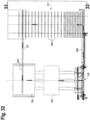
- WO 02/40387 A1 discloses an arrangement to produce a coreless paper roll in a paper producing unit, whereby a finished paper web generated in the production process is wound into a big paper roll, with a diameter over 0,5 m, about a rotating axle, wherein the axle is formed of two parts, the bearing means of both parts are arranged on the outside of the paper winding point, said parts are separable from each other in order to remove the coreless roll from the supporting axle, for the axle rotation is arranged at least from its one end by means of rotating equipment, and heating for axle is arranged by means of heating elements in the axle.
- US 6,047,916 A discloses a reel-up in a paper machine in which the web is reeled onto reeling drums provided with cores, the reel-up having an upper pair of parallel rails extending from the downstream end of the reel-up to its upstream end to support a stock of reeling drums provided with cores, and a handling station for handling finished reels of paper, reeling drums and cores, the handling station having a vertically movable lifting table for receipt of a finished reel of paper, a device for moving a reeling drum out from a reel of paper on the lifting table and for subsequently inserting the reeling drum into at least one core on the lifting table, and a device for feeding cores out onto the lifting table.
- the handling station is provided with a lifting device comprising two lifting elements arranged to be brought into engagement with a reeling drum provided with core(s) and situated on the lifting table, and to lift this and deliver it to the upper pair of rails.
- Actuators are connected to the lifting elements to move them from the lifting table to the delivery point at the upper pair of rails.
- Plastic core tubes have proven to be a reliable key component for many products, particularly those in the film, tape and cloth industries where the core cost is an insignificant part of the overall cost of the product.
- plastic core tubes are not used in bathroom tissue or kitchen towel due to the significantly higher cost over conventional cardboard cores, and also because the plastics are not produced in the paper mills which typically make both the cardboard and tissue products from wood pulp and recycled paper. Additional extrusion equipment and additional transportation of materials would be required to make sufficient plastic cores that could be shipped with the product. This, however, would not be a concern if the plastic cores are removed from the wound product and recycled to wind another product as described hereinafter.
- the mandrel is the starting point and central element. Ideally it would have all the following properties, some of which are countervailing, if not mutually exclusive:
- the mandrel would be just like a circular, tubular cardboard core regarding its radial stiffness and uniformity of cross-section, and it would be similar regarding its mass and inertia. It could then be used to make the same range of products as are made with cores. And this could be done in essentially the same rewinders as use cores. But, how could such a mandrel ever be successfully extracted from a wound log?
- a first non-claimed aspect is a novel lightweight, low inertia mandrel comprised of a relatively thin walled, flexible plastic tube that behaves much like a cardboard core.
- the mandrel is also axially elastic, to facilitate removal from the roll or log of paper which is wound on the mandrel.
- the goal of this mandrel is to replace cardboard cores in new and existing rewinders that currently wind rolls of paper with cores according to a method as defined in claim 1.
- Exemplary surface rewinders of this type are described in Patents US 6,056,229 , US 6,422,501 , US 6,497,383 , US 5,370,335 , US 4,828,195 , and US 7,104,494 , which issued to Paper Converting Machine Company.
- the mandrel can also be used in other models of surface rewinders from this supplier, both continuously operating and start-stop.
- the mandrel can also be used in surface rewinders from other suppliers, for example, and not limited to, rewinders described in Patents US 5,150,848 (Consani ), US 5,979,818 (Perini ), US 6,945,491 (Gambini ), US 7,175,126 (Futura ), US 7,175,127 (Bretting ), US 8,181,897 (Chan Li ), and others.
- the mandrel can also be used in turret rewinders or center rewinders, both continuously operating and start-stop.
- Exemplary center rewinders of this type are described in Patents US 2,769,600 , US 2,995,314 , US 5,725,176 , and US RE 28,353 .
- the mandrel can also be used in turret winders from other suppliers.
- the mandrel can also be used in center-surface rewinders, both continuously operating and start-stop, for example, and not limited to, rewinders described in Patents US 7,293,736 , US 7,775,476 , and US 7,942,363 .
- the second subject of the invention is a novel lightweight, low inertia mandrel comprised of a relatively thick-walled plastic tube, or solid rod, that may have high radial stiffness, but is axially elastic, to facilitate removal.
- the goal of this mandrel is to replace the relatively rigid winding mandrels in new and existing rewinders that make coreless products with holes.
- An exemplary surface rewinder of this type is the coreless embodiment described in Patent US 6,056,229 .
- the mandrel can also be adapted for use in coreless surface rewinders from other suppliers, for example, and not limited to, rewinders described in Patents IT 1,201,390 , US 6,565,033 , US 6,595,458 , US 6,752,345 , and Publication US 2009 0272835 A1 .
- Each of the foregoing novel mandrels is used in a rewinder to form a new product, namely, a roll or log of wound paper comprising the novel mandrel and a web of paper which is convolutely wound around the mandrel.
- the first layer of the convolutely wound paper is adhesively attached to the mandrel, a step which is referred to as transfer.
- the mandrel is withdrawn or extracted from the log by pulling on one or both ends of the mandrel.
- the withdrawn mandrel can be recycled, i.e., recirculated to the rewinder for use in forming another log by winding the web of paper around the mandrel.
- the purpose of the axial elasticity of the two novel mandrels is to allow the mandrel to elongate longitudinally during the step of extracting the mandrel from the log of paper.
- Longitudinal elongation of the mandrel results in localized progressive breakaway of the mandrel from the log, greatly reducing the peak extraction force. This effect is believed to be more important than diameter reduction of the mandrel.
- Longitudinal elongation of the mandrel also results in diameter reduction of the mandrel, which facilitates withdrawal of the mandrel from the log.
- the relationship between the amount of longitudinal elongation and the amount of diameter reduction depends on the Poisson's ratio of the material of the mandrel
- a tubular elastic mandrel can be pressurized before or during winding to expand the mandrel and increase its diameter and, if the ends are not restrained, to decrease its length. After winding, the pressure can be removed, resulting in a reduction of the diameter of the mandrel and an increase of its length, which facilitates withdrawal of the mandrel.
- This method can also be used with stretching of the mandrel during extraction. The methods are not mutually exclusive and both can be employed to achieve greater reduction of the peak extraction force together than either does alone.
- a mandrel chuck for gripping one or both ends of the foregoing tubular' mandrel and withdrawing the mandrel from the log.
- the chuck includes an undersized rigid shaft which is inserted inside of the tubular mandrel to provide internal support.
- Discrete, radially movable blocks are arrayed about the external perimeter of the tube. When the blocks are moved against the tube, the elastic tube deforms into lobes between the blocks. The lobes are mild deformations that are temporary in nature because the stress within the tube material is well below the yield point of the material.
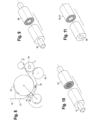
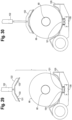
- Figure 1 illustrates a conventional and well known prior art method of winding a web of paper around cardboard cores to form elongated rolls or logs of convolutely wound paper.
- the apparatus illustrated in Figure 1 is a surface rewinder, and the details of the structure and operation of the rewinder are described in U.S. Patent No. 6,052,229 .
- the rewinder of Figure 1 includes three rotating winding rolls 25, 26, and 27 which rotate in the direction of the arrows to wind a web W onto a hollow cardboard core C to form a log L of convolutely wound paper such as bathroom tissue or kitchen towel.
- the first and second winding rolls 25 and 26 are also referred to as upper and lower winding rolls, and the third winding roll 27 is also referred to as a rider roll.
- a stationary plate 28 is mounted below the first winding roll 25 upstream of the second winding roll 26 and provides a rolling surface for the cores. Before the log is completely wound, a new core C1 is introduced into the channel between the first winding roll 25 and the rolling surface 28 by a rotating pinch arm 29.
- Circumferential rings of adhesive have already been applied to the core C1 in the conventional manner.
- the adhesive can be applied to the core in the form of a longitudinally extending stripe, which is also conventional.
- the pinch arm 29 includes a pinch pad 30, and continued rotation of the pinch arm causes the pinch pad to pinch the web against a stationary pinch bar 31 to sever the web along a perforation line in the web.
- the core C1 is moved by the pinch arm along the rolling surface 28 to a position in which it is compressed by the first winding roll 25 and begins to roll on the rolling surface.
- the rings of adhesive on the core pick up the leading portion of the severed web so that the web begins to wind onto the core as the core rolls over the rolling surface.
- the attachment of the web to the core is referred to as transfer.
- the tail end of the severed web continues to be wound up onto the log L.
- the core C1 continues to roll on the rolling surface 28 and winds the web therearound to form a new log.
- the log moves through the nip between the first and second winding rolls 25 and 26 and is eventually contacted by the third winding roll 27.
- the three winding rolls 25-27 form a winding nest or winding cradle for the log.
- Figure 2 illustrates another prior art surface rewinder which winds a web of paper around cardboard cores to form elongated rolls or logs of convolutely wound paper.
- the details of the structure and operation of the rewinder of Figure 2 are described in U.S. Patent No. 5,979,818 .
- the rewinder described in the '818 patent also includes three rotating winding rolls 33, 34, and 35 which rotate in the direction of the arrows to wind a web N onto a hollow cardboard core A to form a log L.
- a curved surface or track 36 extends below the first winding roll 33 toward the second winding roll 34 and provides a rolling surface.
- the rolling surface 36 forms a channel 37 between the first winding roll and the rolling surface.
- a new core Al is introduced into the channel 37 by a conveyor 38 and begins to roll on the rolling surface 36.
- a rotating unit 39 rotates clockwise to cause a pinch pad 40 to pinch the web against the first winding roll 33, causing the web to sever along a perforation line.
- the core Al continues to roll between the surface 36 and the first winding roll 33, adhesive on the core picks up the leading portion of the severed web so that the web begins to wind up on the core to form a new log.
- the tail end of the severed web continues to be wound up onto the log L.
- the log moves through the nip between the first and second winding rolls 33 and 34 and is eventually contacted by the third winding roll 35, which is also called a rider roll.
- the three winding rolls 33-35 form a winding nest or winding cradle for the log.
- a rolling surface like the rolling surface 28 in Figure 1 and the rolling surface 36 in Figure 2 which forms with the first or upper winding roll a channel for inserting the core has become common in the consumer sized tissue and towel converting industry and is practiced by many rewinder suppliers.
- the use of this rolling surface causes the rotation of the core to be accelerated in two abrupt steps.
- the first step takes place between the first winding roll and the rolling surface immediately upon insertion of the core into the channel.
- the second step takes place between the first and second winding rolls, when the log rolls off the end of the rolling surface into the nip formed by the winding rolls. Cores are pushed into the channel with only slight, if any, rotational velocity.
- the first winding roll and rolling surface abruptly accelerate the rotational and translational velocities of the core.
- the first winding roll drives the core along the rolling surface at substantially 1 ⁇ 2 web speed.
- the second step when the core rolls into the nip between the two winding rolls, it immediately loses most of its translational velocity, which is abruptly converted to additional rotational velocity by the spinning rolls.
- the first roll rotates at the web feeding speed and the second roll rotates slightly slower so that the core will move through the nip.
- the dimension of the channel between the rolling surface and the first winding roll is less than the dimension of the core so that the core is compressed as it rolls. Compression of the core in the channel is required for abruptly accelerating the core and for driving the core along the rolling surface.
- the dimension of the nip between the first and second winding rolls is less than the diameter of the core and the initial windings of paper, so the core is compressed as it passes through the nip. Compression of the core in the nip is required for abruptly accelerating the core rotation and controlling its movement through the nip.
- the cardboard cores which are used with the rewinders of Figures 1 and 2 are radially compliant and resiliently compressible so that the core can be compressed as it rolls on the rolling surface and as it passes through the nip.
- coreless rewinders which use rigid mandrels must make accommodations for the radial stiffness of the mandrels so that the mandrels can roll over the rolling surface and pass through the nip without being compressed.
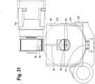
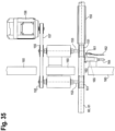
- Figure 3 illustrates another conventional and well known prior art method of winding a web of paper around cardboard cores to form elongated rolls or logs of convolutely wound paper.
- the apparatus illustrated in Figure 3 is a center rewinder or turret rewinder which is sold by Paper Converting Machine Company ("PCMC”) under the name Centrum.
- PCMC Paper Converting Machine Company
- the center rewinder in Figure 3 includes a rotatable turret 45 on which are mounted six mandrels 46.
- mandrel refers to a solid rod over which a conventional cardboard core may be inserted. Circumferential rings of adhesive are applied to the core, and a paper web W is adhesively attached to the core.
- the mandrel on which the core is mounted is rotatably driven to wind up the paper onto the core, and the turret rotates to move the mandrel and core to a position in which the wound roll or log is removed from the mandrel.
- Figures 4 and 6 illustrate novel elongated mandrels 60 and 61 which can be used in place of the cardboard cores which have been described with respect to the prior art rewinders of Figures 1-3 or in place of the rigid mandrels described with respect to prior art coreless rewinders.
- Each of the mandrels includes a longitudinal axis x and is formed from flexible and axially elastic material which will be described in detail hereinafter.
- the mandrel 60 in Figure 4 is a relatively thin walled tube and has an outside diameter OD, and inside diameter ID, and a wall thickness t.
- the mandrel 61 in Figure 6 is a solid rod and has a diameter D. Alternatively, the mandrel could be a relatively thick walled tube or a rod with a small diameter opening.
- the flexible and axially elastic material of the mandrels 60 and 61 contrast with the material of prior art mandrels.
- Mandrels are constructed of various combinations of these high modulus, high strength materials because they must be very strong to withstand the high forces they are subjected to during repeated instances of extraction from logs, without suffering damage.
- the metallic alloys and fiber-reinforced polymer composites are characterized by relatively high elastic modulus and yield strength.
- the fiber-reinforced polymer composites are differentiated by their lower mass density, which affords them a high strength-to-weight ratio.
- Engineering plastics are a group of plastic materials that exhibit superior mechanical and thermal properties in a wide range of conditions over and above more commonly used commodity plastics. The term usually refers to thermoplastic materials rather than thermosetting ones. Engineering plastics are used for parts rather than containers and packaging. Examples of engineering plastics:
- Commodity plastics are plastics that are used in high volume and a wide range of applications, such as film for packaging, photographic and magnetic tape, beverage and trash containers and a variety of household products where mechanical properties and service environments are not critical. Such plastics exhibit relatively low mechanical properties and are of low cost.
- the range of products includes plates, cups, carrying trays, medical trays, containers, seeding trays, printed material and other disposable items. Examples of commodity plastics:
- thermoplastics encompass a huge range of materials with extraordinarily diverse properties. Some are brittle, some are tough. Some are rigid, some are flexible. Some are hard, some are soft. Some are foam. Some are like rubber. But, regardless of the exact natures of specific thermoplastic polymers, they are, as a category, markedly different from metallic alloys and fiber-reinforced polymer composites. In contrast to composite materials which are heterogeneous because of the fiber in the matrix, thermoplastic materials are homogeneous.
- thermoplastic polymers The mechanical properties of plastics are subject to wide variation based on additives and processing methods. However, Table 2 illustrates typical properties of some commonly available thermoplastic polymers.
- polyvinyl chloride are the specification for PVC pipe, also known as rigid PVC.
- polypropylene, polycarbonate, nylon, and high density polyethylene are average values for extrusion grades.
- thermoplastic polymers available there is a subset that is suited for use as a flexible and axially elastic material. There is no scientifically nor commercially accepted name for this category. It is a novel category and has not been used for winding mandrels in coreless rewinders. Definition of the attributes and range of properties that show which materials are in this category is an object of the invention and will be explained in detail. While many attributes play a role, the most important properties are those listed in the chart.
- the stress-strain curve for an aluminum alloy is illustrated on page 148 of The Science and Engineering of Materials, 2nd Edition, by Donald R. Askeland, 1989, by PWS-KENT Publishing Company. ISBN 0-534-91657-0 .
- the elastic modulus is indicated as the slope of the curve in the elastic region, i.e., between zero load (and strain) and the yield strength. If a material is loaded to a stress value less than the yield strength it will return to approximately its original length. The yield strength of this material corresponds to 0.0035 in/in strain. So another way of expressing the yield limitation is if the material is strained less than 0.35% it will return to approximately its original length.
- the elastic modulus is an indication of the stiffness of a material. The higher the modulus value, the greater its resistance to elongation.
- Abbreviated stress-strain curves for steel and aluminum are shown on page 153 of The Science and Engineering of Materials, 2nd Edition, by Donald R. Askeland, 1989, by PWS-KENT Publishing Company. ISBN 0-534-91657-0 .
- the curve for steel has a steeper slope and thus a higher modulus value.
- the tensile yield strength divided by elastic modulus values for the metallic alloys are relatively low.
- the values for the fiber-reinforced polymer composites are also generally low, though they can be manipulated higher by altering the fiber grade, wrap angles, fiber-to-matrix ratio, etc. Nonetheless, it is clear that the values for the thermoplastic polymers are relatively high. The higher this value, the more the material can be elongated without permanent deformation, so materials with higher values are predisposed to work better as axially elastic mandrels.
- thermoplastic polymers may be used as winding mandrels. Some will work better than others. Narrowing the selection down to the best alternatives requires some insight.
- LDPE is attractive because of its high value of tensile yield strength divided by elastic modulus. Its elastic modulus is so low that a thin-walled mandrel, with typical outside diameter, that is long enough for use in a production width rewinder, may be flimsy. Nonetheless, it may work very well in a narrow machine, or with special design considerations to accommodate its flexibility, or for large diameter mandrels. The very low glass transition temperature indicates it is extremely tough.
- PVC pipe may have been used as a winding mandrel in start-stop rewinders and is known to have been used as a winding mandrel to make coreless logs in at least one continuous-running rewinder.
- Rigid PVC is not well suited for use as an axially elastic mandrel, however, because of its low tensile yield strength divided by elastic modulus value. And it cannot be used as a flexible, radially elastic mandrel due to its brittle nature, as indicated by the high glass transition temperature and amorphous structure. Its relatively high density is also a drawback.
- Nylon is superior to rigid PVC in terms of tensile yield strength divided by elastic modulus and its density. But, it is not flexible enough to be a radially elastic mandrel, as indicated by its high glass transition temperature.
- Polycarbonate is an unusual thermoplastic in that it exhibits good toughness even though it is amorphous and has a very high glass transition temperature. It has a high value for tensile yield strength divided by elastic modulus and a fair value for mass density. In its most common forms it is not flexible enough to be a radially elastic mandrel, as indicated by its glass transition temperature; but, if plasticizers can be added to lower its glass transition temperature, without adversely affecting its strength, and other attractive properties, too greatly, it may be viable for an elastic mandrel.
- Polypropylene and HDPE have high values of tensile yield strength divided by elastic modulus, good toughness, and low density. They also have good stiffness and strength values. The lower glass transition temperature of HDPE indicates it is extremely tough and has good flexibility.
- HDPE is the preferred embodiment for reasons touched on here and explained in depth in the following sections, other materials-both existing and those not yet invented nor discovered-that exhibit similar behavior can also be used.
- compliant, axially elastic, low inertia mandrels which are formed in accordance with the invention advantageously have the following physical properties:
- HDPE is the material choice for the preferred embodiment. Though other engineering or commodity plastics could be used, and most of them share at least some of these advantages, HDPE has the best overall combination of advantages and benefits, listed below.
- HDPE can be extruded to have the same circular, tubular, uniform cross-section as a conventional cardboard core. Such tubes happen to have very similar radial stiffness to the core equivalents, which is desirable for a core replacement.
- the HDPE tube can have a thicker wall, to have greater cross-sectional area to bear the tensile load, thereby keeping the peak stress lower, and still exhibit radial stiffness similar to that of a cardboard core with a commensurate outside diameter.
- HDPE high density polyethylene
- typical core board so the mass and polar inertia of the plastic tubes is greater, they are still far lower, and much closer to a core equivalent, than rigid mandrels.
- Table 3 for a comparison of typical cardboard cores to HDPE tubes.
- the table includes values for typical aluminum alloy, steel alloy, carbon fiber-reinforced polymer composite, glass fiber-reinforced polymer composite, and polyvinyl chloride tubes. These values are best case because they are for simple uniform cross-section circular tubes and do not include the mass of the end features on the tubes which are used to cooperate with a grasping means.
- Typical consumer and commercial grades of BRT wound on a 4,38 cm (1.70 inch) OD x 0,09 cm (0.036 inch) wall x 290 cm (114 inch) long HDPE tube require between 133 to 1557 N (30 to 350 pounds) force for mandrel extraction from a log wound from a 267 cm (105 inches) wide web.
- the extraction force varies greatly depending on the tightness of the wind, drying time of the transfer glue, coefficient of friction of the substrate on HDPE, and other factors. Nonetheless, the tensile stress induced by 1557 N (350 pounds) is only 12,8 MPa (1,863 psi), which is well below the tensile yield strength of 27,6 MPa (4,000 psi).
- Figure 8 illustrates the prior art surface rewinder of Figure 1 , but rather than using cardboard cores, the web of paper is wound on lightweight, low inertia, radially compliant, axially elastic mandrels 64 which are formed in accordance with the invention, for example, the tubular mandrel 60 of Figure 4 .
- the mandrels 64 are used to wind paper logs or rolls L in the same way as the cardboard cores which are described in Patent No. 6,056,229 .
- Figure 8 illustrates a web of paper W forming a first log L which is being wound on a first mandrel 64 between the second and third winding rolls 26 and 27.
- a new mandrel 64a is introduced into the channel between the first winding roll 25 and the rolling surface 28 by the rotating pinch arm 29.
- a linear stripe of transfer glue or adhesive has already been applied to the mandrel 64a in the conventional manner.
- circumferential rings of adhesive can be applied in the conventional manner.
- Continued rotation of the pinch arm 29 causes the pinch pad 30 to pinch the web against the stationary pinch bar 31 to sever the web along a perforation line in the web.
- the mandrel 64a is moved by the pinch arm along the rolling surface 28 to a position in which the radially compliant and low inertia mandrel is compressed and accelerated by the first winding roll 25 and begins to roll on the rolling surface at approximately 1 ⁇ 2 of the web speed.
- the adhesive on the mandrel picks up the leading portion of the severed web so that the web begins to wind onto the mandrel as the mandrel rolls over the rolling surface.
- the tail end of the severed web continues to be wound up onto the log L.
- the mandrel 64a continues to roll on the rolling surface 28 and winds the web therearound to form a new log.
- Mandrels 64 can also be used in place of cardboard cores in the prior art rewinders which are illustrated in Figures 2 and 3 , as well as other rewinders which wind a paper web onto a cardboard core. In each case, the rewinder can wind the paper onto the mandrels in the same way as the rewinder winds paper onto cardboard cores.
- the axially elastic solid mandrel 61 of Figure 6 can be used to wind coreless paper logs or rolls L in the same way as the rigid mandrels which are described in Patent US 6,056,229 with the same transfer and winding depicted in Figures 13 and 14 of that patent.
- Figure 9 illustrates a log 66 of paper which has been convolutely wound on a tubular mandrel 60 by any of the rewinders which have been discussed herein.
- Figure 10 illustrates a log 67 of paper which has been convolutely wound on a solid mandrel 61 by such a rewinder.
- the mandrel preferably extends beyond one or both ends of the log of paper so that the mandrel can be extracted or withdrawn from the log by grasping one or both ends of the mandrel.
- Figure 11 illustrates the log 66,67 of either Figure 9 or Figure 10 after the mandrel has been withdrawn.
- An axially extending central opening 68 extends through the log.
- the force to extract a rigid mandrel from a log is linear with respect to the length of the mandrel-log engagement after relative motion is established.
- the force to initiate relative motion is actually much greater, so the graph of the force profile has steps in it.
- the following values are provided as an example to illustrate the point.
- the measured extraction forces will vary greatly depending on tightness of the wind, drying time of the transfer glue, coefficient of friction of the substrate on the mandrel surface, and other factors. Measurements of the force required to strip logs were recorded on the PCMC coreless machine described in U.S. Patent No. 6,056,229 .
- the product was a tightly wound, very dense bathroom tissue.
- the log length (web width) was 254 cm (100 inches).
- the mandrel was of the rigid type, made of alloy steel tube, with outside diameter of 1,74 cm (0.688 inches).
- the force to break the log free of the mandrel, initiating relative motion was about 5160 N (1,160 lbs). This force level was of very brief duration, exhibiting the appearance of an upward spike in the graph.
- the force immediately dropped to 1334 N (300 lbs), which was the level to maintain relative motion with 254 cm (100 inches) of mandrel-log engagement.
- the force decreased linearly as the mandrel withdrew until it reached zero at the moment the mandrel end exited the log (no mandrel-log engagement).
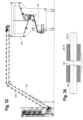
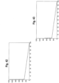
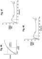
- Figure 42 shows actuator force vs. actuator position for this case of rigid mandrels. Less tightly wound products require less stripping force, and thus have lower force values on their graphs, but the general shape of their graphs is the same.
- the breakaway force is very high relative to the stripping force. It is 3.87 times larger.
- the stripping force, after relative motion is underway, is only 26% as much as the breakaway force.
- the mandrels, the stripping (or extraction) hardware, actuator drive train, and actuator must be designed to accommodate the very high initial force to initiate relative motion.
- the peak force can be greatly reduced. Instead of breaking free of the mandrel all at once, as with rigid mandrels, elastic mandrels break free progressively and smoothly as they stretch within the log. The mandrels can be stretched in this fashion, due to their relatively low elastic modulus values. And because the peak force is far less, the peak stress is far less, so the relatively low strength plastic mandrels are strong enough.
- Figure 43 shows the case of an axially elastic mandrel being withdrawn from the same product according to the method of claim 1 and discussed with respect to Figure 42 .
- the graph assumes the same coefficient of friction, though the value for HDPE could be lower. It shows the case of the mandrel being pulled from just one end, where mandrel elongation causes it to progressively and smoothly break free over one-half of the log length before the other half breaks free suddenly.
- the height of the spike above the 134 N (300 lbs) stripping force is reduced by one-half, from 5160 N to 3247 N (1,160 lbs to 730 lbs).
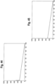
- Figure 44 shows the case of an axially elastic mandrel being withdrawn from the same product.
- the graph assumes the same coefficient of friction, though the value for HDPE could be lower. It shows the case of the mandrel being solely pulled from one end until mandrel elongation has caused it to progressively and smoothly break free over nearly one-half of the log. Then, before the other half breaks free suddenly, an actuator at the other end of the mandrel begins to push the mandrel in the same direction. The other one-half of the mandrel still breaks free suddenly, but the load is shared nearly evenly between the two actuators.
- the height of the spike above the 1334 N (300 lbs) stripping force is reduced by three-quarters, from 5610 N to 2291 N (1,160 lbs to 515 lbs). If the 2291 N (515 lbs) peak force is acceptable for the mandrel cross-section, because the induced tensile stress is low enough relative to the yield strength of the material, then this pulling-pushing method may be utilized.
- Figure 45 shows the case of an axially elastic mandrel being withdrawn from the same product.
- the graph assumes the same coefficient of friction, though the value for HDPE could be lower. It shows the case of the mandrel being pulled from both ends until mandrel elongation has caused it to progressively and smoothly break free over the entire length of the log, so no segment breaks free suddenly.
- the load is shared nearly evenly between the two actuators. After the entire length of mandrel is in motion relative to the log the second puller reverses direction and releases before touching the face of the log. This sequence can be precisely timed and controlled because both actuators have servo motion control with electronic feedback signals. Thus the spike above the 1334 N (300 lbs) stripping force can be eliminated.
- the 1334 N (300 lbs) peak force is acceptable for the mandrel cross-section, because the induced tensile stress is low enough relative to the yield strength of the material, then this mandrel stretching method may be utilized. If it is not, then additional measures can be employed to further reduce the peak force, such as implementing pressurized expansion during winding, as described later in this document.
- the preceding values are comparative illustrations extrapolated from measured values, not absolute values. It was stipulated, for instance, that pulling the mandrel from one end would cause it to progressively and smoothly break free within one-half the length of the log. In reality, the proportion that breaks free gradually in this fashion may be more or less, depending on the cross-section of the mandrel, the tightness of the wind, and other factors.
- the offset yield strength method is often used to define the yield point for highly ductile metals.
- a construction line is drawn parallel to the initial portion of the stress-strain curve. Its intersection with the horizontal axis is offset by 0.002 from the origin.
- the 0.2% offset yield strength is the stress at which the construction line intersects the stress-strain curve as shown on page 151 of The Science and Engineering of Materials, 2nd Edition, by Donald R. Askeland, 1989, by PWS-KENT Publishing Company. ISBN 0-534-91657-0
- Tensile testing is performed by elongating a specimen and measuring the load carried by the specimen. From a knowledge of the specimen dimensions, the load and deflection data can be translated into a stress-strain curve. A variety of tensile properties can be extracted from the stress-strain curve.
- the yield point is defined as when an increase in strain does not result in an increase in stress. This means the yield point coincides with the first inflection point on the HDPE stress-strain curve. This is well beyond both the proportional limit and elastic limit of the material.
- the elastic modulus (slope of the curve) is calculated between 0.05% strain and 0.25% strain. This is very close to the origin, at relatively low strain values, compared to how much thermoplastic polymers can stretch, and how much the elastic mandrels are expected to safely elongate in service.
- Figure 47 identifies the yield point of HDPE on a stress-strain curve.
- the horizontal line is the yield strength (S y ), drawn at about 30 MPa (4,350 psi).
- the vertical line is the strain at yield ( ⁇ y ), drawn at nearly 11 %.
- the proportional limit of a material is the point beyond which the linear relationship of Hooke's Law is no longer valid.
- the elastic limit of a material is the point beyond which the material does not fully recover to its original length when the load is removed.
- Figure 48 is similar to Figure 47 but has additional lines drawn on it.
- the diagonal line is drawn tangent to the curve at the origin and represents the modulus of elasticity (E).
- the vertical line is drawn where the diagonal line intersects the yield strength line and represents the yield strength divided by elastic modulus ( ⁇ 0 ).
- the short horizontal line is drawn from where the new vertical line intersects the stress-strain curve and represents the stress ( ⁇ o ) corresponding to the yield strength divided by elastic modulus ( ⁇ o ).
- HDPE properties of HDPE vary depending on supplier and processing method. The amount of information they provide regarding the mechanical properties of their resins also varies. Nearly every supplier can provide at least values for the elastic modulus (E) and yield strength (S y ), however. Our experience with HDPE tubes has shown that the following guidelines are good when designing elastic mandrels.
- the elastic portion of the mandrel can be elongated by one-half to two-thirds of ⁇ o during extraction from the log and still return close enough to its original length, rapidly enough, to be recirculated in a continuously operating coreless rewinder. (This is possible because the machine must accommodate some tolerance in mandrel length anyway, and the variation falls within the tolerance of the machine. Machines operating at higher cycle rates may require a greater quantity of mandrels in circulation, or that mandrels be elongated less during extraction.
- a mandrel strained to this degree does not immediately return to its original length because it was strained beyond the elastic limit of the material. However, it does eventually return to its original length. The return to original length occurs most rapidly at first and more slowly as the mandrel approaches its original length. It may take several hours for the mandrel to restore itself completely to its original length because the last millimeters take the longest.
- the elastic portion of the mandrel can be subjected to greater elongation without permanent deformation nor damage when it is loaded (stretched) more slowly. When loaded more rapidly it is more likely to experience localized draw or even tearing.
- HDPE and other thermoplastic polymers respond to stress with the behaviors of both elastic solids and viscous fluids. This characteristic is referred to as viscoelasticity.
- the properties of viscoelastic materials are subject to change based on the variables of load application rate, load duration (time), and temperature.
- the viscoelastic behavior of HDPE explains the behaviors outlined in the paragraphs above.
- Load application rate is quite simple. When the load is applied more rapidly, the material appears to be stiffer (reacts with higher elastic modulus). When the load is applied less rapidly, the material reacts with lower elastic modulus. This behavior is illustrated on page 151 of History and Physical Chemistry of HDPE, by Lester H. Gabriel, Ph.D., P.E. http://www.plasticpipe.org/pdf/chapter-1_history_physical_chemistry_hdpe.pdf
- a computerized servo system with feedback should be used to properly control, and allow adjustments to, the motion profiles applied to the mandrel, for both stretching and extracting.
- Viscoelastic materials creep under constant stress and relax under constant strain. This means that a winding mandrel composed of a viscoelastic material subjected to a fixed load will continue to elongate. It means that the same mandrel subjected to a fixed elongation will undergo a reduction in stress. It is as though the elastic modulus of the material decreases over time. Therefore, to maintain constant elongation an actuator must reduce the applied force over time.
- a computerized servo system with feedback should be used to properly control, and allow adjustments to, the force applied to the mandrel, for both stretching and extracting.
- T g glass transition temperature
- T m melting point temperature
- the polymer remains as a melt or liquid.
- the polymer behaves much like a rubber. They appear leathery or rubbery.
- a useful rubber is a polymer having its T g well below room temperature. As they approach the glass transition temperature from above, polymers become stiffer and pass through a temperature called the brittle point, slightly higher than the glass transition temperature. By this point their flexible nature and rubbery properties have gradually been lost. The material is stiffer and harder and will break or fracture on sudden application of load.
- T g is a common reference point for polymers of diverse nature, below which all of them behave as stiff rigid plastics (glassy polymer). In common usage a useful plastic is one whose T g is well above room temperature.
- Molecular weight and molecular weight distribution, external tension or pressure, plasticizer incorporation, copolymerization, filler or fiber reinforcement, and cross linking are some of the important factors that influence the glass transition and melting point temperatures.
- External plasticizer incorporation is very effective at lowering the glass transition temperature and can be used to reformulate polymers that are stiff and rigid at room temperature into polymers that are flexible and rubbery at room temperature.
- the publication plots dynamic modulus (stiffness) versus material temperature for loads of short duration.
- the points of rapid drop-off on the curves coincide with the glass transition temperatures. For the most part these points lie between 37,7° C to 260° C (100° F to 500° F), with the majority above 65,5° C (150° F).
- the glass transition temperature for HDPE is about -84,4 to - 90° C (-120 to -130° F). Its brittle point temperature is below - 62,2° C (-80° F). Its softening point temperature is about 121,1° C (250° F). Its melting point temperature is 129,4° C ( 265° F).
- the operating temperature of a mandrel composed of HDPE is well above the glass transition and brittle point temperatures, and well below the softening and melting point temperatures.
- the material has such a good combination of pliability, stretch-ability, durability, and toughness that make it well suited for use as a winding mandrel, especially the radially compliant, thin-walled variety that can act as a core equivalent.
- PE piping material consists of a polyethylene polymer (commonly designated as the resin) to which has been added small quantities of colorants, stabilizers, antioxidants and other ingredients that enhance the properties of the material and that protect it during the manufacturing process, storage and service.
- PE piping materials are classified as thermoplastics because they soften and melt when sufficiently heated and harden when cooled, a process that is totally reversible and may be repeated. In contrast, thermosetting plastics become permanently hard when heat is applied.
- PE is a thermoplastic
- PE pipe and fittings can be fabricated by the simultaneous application of heat and pressure.
- PE piping can be joined by means of thermal fusion processes by which matching surfaces are permanently fused when they are brought together at a temperature above their melting point.
- PE is also classified as a semi-crystalline polymer.
- Such polymers e.g., nylon, polypropylene, polytetrafluoroethylene
- those that are essentially amorphous e.g., polystyrene, polyvinylchloride
- have a sufficiently ordered structure so that substantial portions of their molecular chains are able to align closely to portions of adjoining molecular chains. In these regions of close molecular alignment crystallites are formed which are held together by secondary bonds. Outside these regions, the molecular alignment is much more random resulting in a less orderly state, labeled as amorphous.
- semi-crystalline polymers are a blend of two phases, crystalline and amorphous, in which the crystalline phase is substantial in population.
- T g glass transition temperature
- a significantly lower T g endows a polymer with a greater capacity for toughness as exhibited by performance properties such as: a capacity to undergo larger deformations before experiencing irreversible structural damage; a large capacity for safely absorbing impact forces; and a high resistance to failure by shattering or rapid crack propagation.
- the T g for PE piping materials is approximately -90° C (-130°F) compared to approximately 105°C (221°F) for polyvinyl chloride and 100°C (212°F) for polystyrene, both of which are examples of amorphous polymers that include little or no crystalline content.
- HDPE is an excellent choice of material for an elastic mandrel
- other materials can be used.
- polypropylene has a fair amount of pliability, stretch-ability, durability, and toughness because it also has a glass transition temperature below ambient.
- Materials with glass transition temperatures above ambient such as nylon and polycarbonate, may also work, for instance, as axially elastic mandrels. These would be useable in rewinders that accept radially rigid mandrels and they would offer at least the advantages of low cost, low mass, low polar inertia, and reduced extraction force.
- GS Nylon 3172 MPa (460,000 psi)
- polycarbonate 2413 MPa (350,000 psi)
- GS Nylon 86,2 MPa (12,500 psi)
- polycarbonate 65,5 MPa (9,500 psi)
- plasticizers may be added to some of these materials to shift T g from above ambient to below ambient, if this does not also reduce the strength, and other attractive properties, too greatly.
- PVC pipe may have been tried in the past on some rewinders and may even be in use now on some rewinders.
- PVC pipe may have been tried as an alternative to the metallic alloy mandrels used in start-stop coreless rewinders and is known to have been used as a winding mandrel to make coreless logs in at least one continuous-running rewinder.
- Rigid PVC pipe is appealing relative to metallic alloys and fiber-reinforced composites because it is readily available, machinable, low friction, inexpensive and relatively lightweight.
- PVC pipe is an amorphous thermoplastic with a high glass transition temperature. Because its glass transition temperature is far above ambient, it is stiff and relatively brittle in service, especially when subjected to sudden loads.
- Table 2 that shows typical mechanical properties for various polymers, presented earlier in this document, lists values for 'rigid' PVC (low plasticizer content) that is used in commercially available pipe. These values are from the following web sites. http://www.professionalplastics.com/professionalplastics/PVCPipeSpecifications.pdf http://www.sd-w.com/civil/pipe_data.htm
- the glass transition temperature of PVC is over 70° C (158° F).
- the result is low impact strength at room temperature, which is one of the disadvantages of PVC.
- the foregoing web site has a chart showing the energy absorbed by test pieces of various plastic materials when they are fixed and hammered to break (failure). Higher values indicate higher impact strength.
- Rigid PVC is at the low end of the scale.
- the foregoing web site also has charts showing comparisons of PVC tensile elastic modulus to other plastics, and comparisons of PVC tensile strength to other plastics.
- PVC pipe material could work as a radially rigid, somewhat axially elastic mandrel. But, its lower value of tensile yield strength divided by elastic modulus makes it less well suited to this application because, for many products, high stress levels would be reached before adequate elongation is achieved.
- Plasticizers can be added to PVC to shift its glass transition temperature from above ambient to below ambient. PVC readily accepts plasticizers and this is commonly done. If this does not also reduce the strength, and other attractive properties, too greatly, it may be viable for an elastic mandrel. Use of this material would also then lie within the novelty of the present invention.
- Plasticizers can shift the glass transition temperature so far that PVC becomes softer, flexible, even rubbery. In these forms it is used in clothing and upholstery, electrical cable insulation, inflatable products, automotive parts, and many applications in which it replaces rubber. With the addition of impact modifiers and stabilizers, it has become a popular material for window and door frames, also vinyl siding. It seems feasible that a formulation may exist, or be created, that could meet the requirements of an acceptable radially and axially elastic mandrel.
- Polyvinyl chloride is a versatile thermoplastic with the widest range of applications of any of the plastics family making it useful in virtually all areas of human activity.
- PVC polyvinyl styrene
- PVC products can be rigid or flexible, opaque or transparent, colored and insulating or conducting. There is not just one PVC but a whole family of products tailor-made to suit the needs of each application.
- PVC polystyrene resin
- the essential additives for all PVC materials are stabilizers and lubricants. In the case of flexible PVC, plasticizers are also incorporated.
- Other additives which may be used include fillers, processing aids, impact modifiers and pigments. Additives will influence or determine the mechanical properties, light and thermal stability, color, clarity and electrical properties of the product. Once the additives have been selected, they are mixed with the polymer in a process called compounding.
- stereospecific regions When sufficiently long stereospecific regions become close together during polymerization (or during cooling from a melt hot enough to be amorphous), they join to form a crystalline region, binding together different regions of the same molecule and parts of adjacent molecules.
- the structure of these crystallites varies in perfection depending on the amount, size, regularity, and thus compatibility of the stereospecific regions. They are believed to be spaced on average about 10 nm apart and usually constitute about 7-10% of the polymer structure [6].
- PVC polystyrene-co-styrene-co-styrene-co-styrene-co-styrene-co-styrene-co-styrene-co-styrene-co-styrene-co-styrene-co-styrene-co-styrene-co-styrene-co-styrene-styrenephthalate terpolyrene-styrene-styrene-styrene-styrene-styrene-styrene-styrene-styrene-styrene-styrene-styrene-styrene-styrene-styrene-styrene-styrene-styrene-styrene-styrene-styrene-styrene-
- a whole spectrum of structures, spanning near total disorder, different kinds and degrees of order and near total order, may describe the physical state of a given polymeric system, depending on test environment, nature of polymer and its synthesis route, microstructure and stereo-sequence of repeat units, and thermomechanical history of the test specimen. Further, the collected data for degree of crystallinity may also vary depending on the test method employed. The degree of crystallinity data shown in Table 2 must therefore be taken as approximate. Polymers showing degrees of crystallinity greater than 50% are commonly recognized to be crystalline The predominantly linear chain molecules of high-density polyethylene (HDPE) show a degree of crystallinity that is much higher than any other polymer known (even substantially higher than that for the low-density polyethylene (LDPE).
- HDPE high-density polyethylene
- the attainable crystallinity degree is close to the upper limit (100%).
- Atactic polymers in general including those of methyl methacrylate and styrene bearing bulky side groups), having irregular configurations fail to meaningfully crystallize under any circumstances.
- Table 2 Approximate Degree of Crystallinity (%) for Different Polymers. Polymer Crystallinity (%) Polyethylene (LDPE) 60 - 80 Polyethylene (HDPE) 80 - 98 Polypropylene (Fiber) 55 - 60 Nylon 6 (Fiber) 55 - 60 Terylene (Polyester Fiber) 55 - 60 Cellulose (Cotton Fiber) 65 - 70
- the mandrel outer diameter (OD) is dictated by the required hole diameter in the finished product.
- the mandrel inside diameter (ID), and thus the wall thickness, are determined by the required cross-section area.
- the goal is to fully utilize the recommended maximum strain of one-half to two-thirds of the yield strength divided by elastic modulus ( ⁇ o ). This strain corresponds to an initial induced stress of somewhat less than one-half to two-thirds of the yield strength (S y ), because of the nonlinear response of stress to strain. If actual stress-strain curve data are available it is best to use that. However, the linear relationship of Hooke's Law is used below for simplicity.
- the target value for ⁇ is defined.
- the applied force is not an independent variable.
- the force is dictated by the interaction of the log and mandrel.
- the only independent variable in the equation is the area of the cross-section.
- stretching the mandrel does not add to the magnitude of the extraction force. If it did, then this method of stretching an elastic mandrel during extraction could be self-defeating and thus less useful in practice. But, it does not. It is akin to lifting a 100 pound weight with an elastic strap instead of an inelastic steel chain. The lift force remains unchanged at 100 pounds. Perhaps more work is done because the strap is elongated in addition to the weight being lifted, but the force is the same.
- an elastic mandrel ensures reasonable extraction forces without product damage when producing tightly wound coreless logs. It overcomes the issue of high interlayer pressure. Using an elastic mandrel with log end face and log peripheral restraint during mandrel extraction ensures low extraction forces without telescoping or crumpling when producing loosely wound, low density coreless logs. It overcomes their issues of low interlayer pressure (telescoping) and low column strength (crumpling).
- the device that applies pressure on the log to restrain the periphery of the log must have its travel limited after it contacts the log surface (for instance, rod locks on pneumatic cylinders, or a servo actuator with feedback), or it will compress loosely wound, low density logs flat as the mandrel is withdrawn.
- the log In state of the art coreless rewinders the log is supported by a trough, below, and restrained in the axial direction solely by a plate against its end face as either the mandrel is pulled out or the log is pushed off.
- the flexible member that communicates the force from the actuator to the mandrel (in the case of pulling) or the plate (in the case of pushing), be it chain, timing belt, cable, or other, is laterally offset from the mandrel centerline, so the extraction force (pulling) or the stripping force (pushing) produces large moment loads on the guide tracks for the clasp (pulling) or the plate (pushing).
- Substantial frames, brackets, and guide ways are required to oppose these large moment loads. This increases the cost and space required, and reduces the practical speed at which they operate. And it is a frequent complaint that the guide ways wear out prematurely.
- the arrangement of the pulleys and path of the timing belt in this invention allows the extraction force to be placed substantially coincident with the mandrel centerline. This makes the moment load minimal, or substantially zero.
- mandrel have a non-uniform cross-section to provide a surface transverse to the longitudinal axis of the mandrel for the clasp to cooperate with is a valid alternative. It can be done with a homogeneous mandrel by fusing a shape onto the mandrel at or near the end, hot working a feature into the mandrel at or near the end, cold working a feature into the mandrel at or near the end, machining a feature into the mandrel at or near the end, or similar.
- the clearance has variability. Lower cost mandrels will have greater variability (manufacturing tolerance). If a clasp requires higher precision mandrels, then it is requiring higher cost mandrels.
- the standard tolerances quoted for normal commercial extrusion of HDPE mandrels with 4,32 cm (1.700-inch) OD x 0,09cm (0.036-inch) wall thickness are ⁇ 0,02 cm ( ⁇ 0.010 inches) at the outside diameter and also ⁇ 0.010 inches at the inside diameter. This means the wall thickness itself may vary ⁇ 0,02 cm ( ⁇ 0.010 inches).
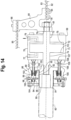
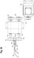
- Figures 12-18 illustrate the preferred embodiment of a clasp 69 according to claim 12 that can cooperate with a thin-walled elastic mandrel with uniform cross-section.
- a pneumatic cylinder assembly 70 includes a cylindrical body 71 and a piston 72 which includes right and left rod ends 73 and 74.
- the piston 72 is slidable within a bore 75 in the cylinder, and the bore communicates with a source of pressurized air through ports 76 and 77.
- the cylinder 71 is a short stroke, large bore cylinder.
- a clamping assembly 88 is mounted on the left rod end 74 and is adapted to clamp a tubular mandrel 60.
- the clamping assembly includes a cylindrical housing 89 and a cylindrical central prong or shaft 90 which is sized for insertion into the bore of the tubular mandrel.
- the prong has an abridged bullet nose 91 to ensure that it enters the mandrel even if the mandrel and the log which is wound on the mandrel are misaligned with the clasp 69.
- the diameter of the prong has a manufacturing tolerance. Its maximum diameter is specified so it is always less than the minimum possible diameter of the mandrel. Thus, every mandrel has radial clearance between its inside diameter and the prong. The clearance varies. The clearance is maximum when the mandrel inside diameter is at its upper tolerance limit and the prong diameter is at its lower tolerance limit.
- An actuating wedge 101 is mounted radially outwardly of each of the clamping blocks 92.
- Each of the actuating wedges includes an inclined inner wedge face 102 which engages the wedge face 96 of the associated clamping block and an axially extending outer face 103 which engages a cylindrical surface 104 of the housing 89. The engagement of the faces 103 and 104 ensures that the actuating wedges move axially within the housing 89.
- Each actuating wedge 101 is provided with a bore 105 through which a bolt 98 extends, and each actuating wedge is secured to the cylindrical body 71 by a bolt 106 which is screwed into the wedge. The head 107 of each bolt 106 is secured to the cylindrical body by a clamping plate 108 and a nut 109.
- the clamping blocks 92 are spaced radially outwardly from the cylindrical prong 90 to permit a tubular mandrel to be inserted between the prong and the blocks.
- Figure 14 illustrates the end of a tubular mandrel 60 inserted over the prong 90.
- the piston 72 is in the disengaged position in which the piston engages the left face 110 of the bore 75 of the cylinder 71.
- the piston is maintained in the disengaged position by pressurized air which enters the port 76, and port 77 is vented.
- the clamping blocks exert nearly 17793 N (4,000 lbs) on the mandrel. Therefore, if the coefficient of friction of the blocks on an HDPE mandrel is 0.3, the holding force will be nearly 5338 N (1,200 lbs). If this amount is not adequate, the coefficient of friction can be increased with friction coatings on the blocks and the internal prong, perhaps raising it to 0.5, and thereby the holding force at 0,41 MPa (60 psig), to nearly 8896 MPa (2,000 lbs).
- FIG. 17 shows how the mandrel 60 deforms when loaded by the clamping blocks 92 against the prong 90 inside the mandrel.
- the axial load is communicated through sixteen surfaces at the eight regions of substantially linear contact between the eight clamping blocks 92, the mandrel, and the prong 90.
- the mandrel only gently deforms in the regions between the blocks.
- the shape of the cross-section of the mandrel temporarily takes on the appearance of lobes or waves 111 between the clamping blocks.
- the maximum bending stress is at the inflection points.
- the magnitude of this stress is quite low because the radius of curvature of the lobes is large.
- the size of the mandrel in the embodiment illustrated is 4,32 cm (1.700-inch) OD x 0,09 cm (0.036-inch) wall thickness.
- Eight clamping blocks 92 easily operate about its periphery. In fact, the same eight blocks can operate about the periphery of a mandrel as small as 2,54 cm (1.000-inch) OD. An obvious variant is that for smaller diameter mandrels the quantity of blocks can be reduced.
- the preferred embodiment has eight blocks to ensure good distribution of the force transmission, to avoid localized high stress points that could cause the mandrel material to yield or tear at very high axial forces, maximizing mandrel life, but fewer blocks can be used.
- a preferred mandrel tube is found to lack concentricity, that is, the wall thickness is not substantially uniform about the entire perimeter, provision can be made for the clasp to accommodate this.
- Compliance may be added to the screws 106 that push the actuating wedges 101 forward, driving the clamping blocks down. This compliance may be a polyurethane washer, compression spring, or similar. The compliance may also be used to compensate for uneven wear of the wedges, if this is found to be a problem.
- the preferred embodiment of the clasp does not possess a means to push the mandrel back out. It is expected that an external device, or pair of devices, will assist with drawing the mandrel out. For instance, after the clasp has withdrawn a majority of the mandrel length from a log, two clamps, one disposed closer to the operator side and the other disposed closer to the drive side, would actuate to lightly pinch the mandrel. The surfaces would be covered in a material that provides drag against further axial travel of the mandrel, but does not prohibit further axial travel nor mark the mandrel. After the mandrel end has withdrawn from the end of the log and the face plate adjacent thereto, these clamp devices would keep it from falling, maintaining the mandrel horizontal to the floor.
- the clasp would be nearing its stopping position. Before stopping the clasp would release and the clasp would travel a little farther at slow speed to its stopping position. The drag imposed on the mandrel by the clamps would cause the mandrel motion to cease before the clasp motion, drawing the mandrel out of the clasp. The clamps would then simultaneously release, allowing the mandrel to fall into the return guides, or onto a conveyor.
- An alternate embodiment may possess an integrated means to push the mandrel back out of the clasp rather than utilizing an external device or devices.
- An alternate embodiment is the implementation of a manually actuated device.
- This device may be hand-held and used to withdraw mandrels from relatively loosely wound logs, where the extraction forces are low. Because the forces are low the device can use fewer blocks at the mandrel periphery and more aluminum and plastic parts to be kept lightweight.
- the blocks may be loaded with cam levers or over-center lever latches instead of wedges to further reduce weight, cost, and complexity.
- the target customer would be in markets where labor cost is low relative to capital equipment cost. (Though it would be taxing to do it for hours, it is eminently feasible. The proof of concept of using thin-walled HDPE winding mandrels was done on a machine with manual mandrel extraction.)
- a different embodiment that acts similarly would be to use a rigid ring outside the mandrel, with moving wedges, or blocks, inside. Instead of the mandrel wall segments between the blocks bulging outward, they would draw straighter, like chords running between the crowns of the blocks. The lobes (or wave crests) would be in-line with the wedges, rather than between them.
- the major disadvantage of this approach, relative to the preferred embodiment, is it does not work with small diameter mandrels. Even for moderate diameter mandrels the mechanisms inside the tube would have to be relatively intricate to fit.
- Figures 19-28 illustrate the steps of the preferred method of extracting an elastic mandrel 60 from a log 66 when the mode of stretching the mandrel within the log by pulling both ends is employed.
- the left clasp and drive may be replaced with a simple linear actuator, such as a pneumatic cylinder, to push the log end face against the restraint plates 123 and 124.
- a simple linear actuator such as a pneumatic cylinder
- the pushing-pulling method is utilized to stretch and withdraw the mandrel
- the left clasp does not pull the mandrel, but only pushes it, and can be preplaced with a simpler non-actuating device.
- Servo motion control is still recommended for proper timing. When adequate, it has the advantages of somewhat less cost and potentially higher cycle rate.
- the log is supported in a log support trough 120 on the frame.
- a lower peripheral log restraint 121 is mounted on the trough.
- An upper peripheral log restraint 122 above the log is positioned to engage the top of the log.
- a right (or operator side) clasp 69R is positioned to engage the right end of the mandrel 60, and a left (or drive side) clasp 69L is positioned to engage the left end of the mandrel.
- Log end face restraint plates 123 and 124 are positioned to engage the right face of the log.
- Figure 28 the log is discharged from the trough 120 so that the next log can enter.
- the mandrel 60 is dropped by the clamps 127 and 128 into return guides 129 for recirculation to the winding machine, or the mandrel could be deposited directly onto a conveyor for recirculation to the winding machine.
- the right clasp 69R begins returning to the left for the next log after the mandrel has moved out of the way.
- Figure 29 is an end view of the log 66, the upper peripheral restraint 122, the log support trough 120, and the lower peripheral restraint 121.
- the peripheral restraints are disengaged from the log.
- the upper restraint 122 includes a generally V-shaped cover 131 which is raised and lowered by an actuator 132.
- the inclined sides of the cover 131 which engage the log are provided with a rough surface 133.
- the trough 120 has a smooth surface which engages the log and is provided with an axially extending gap 134 in which the lower restraint 121 is mounted.
- the lower restraint has a rough surface for engaging the log and is raised and lowered by an actuator 135.
- Figure 31 is a view similar to Figure 30 but also shows the end face restraint plates 123 and 124 and the timing belt 83 which is colinear with the centerline of the mandrel 60 so that the extracting force in the timing belt is axially aligned with the mandrel.
- Figure 33 is an end view of the recirculation path of the mandrels.
- the conveyor 141 delivers the mandrels 60C to a hopper 142 which includes a discharge chute 143.
- the mandrels are fed by the discharge chute to the infeed conveyor 137.
- the extraction force is too great to use a radially compliant, thin-walled mandrel, even when the mandrel is elongated during extraction to minimize the breakaway force, the mandrel can be made with thicker walls, or even solid. However, this action would forfeit numerous advantages of the thin-walled mandrel.
- its novel monocoque construction permits the alternative of inflating the mandrel while winding the log, then removing the internal fluidic pressure later in the winding process, or after winding is complete, allowing the mandrel to deflate and return nearly to its original size, before the log is pushed off or the mandrel is pulled out.
- This method may be employed instead of stretching of the mandrel within the log by pulling both ends during extraction.
- the former operates during winding and the latter operates during extraction, they are not mutually exclusive and both can be employed to achieve greater reduction of the peak extraction force together than either does alone.
- Monocoque is a construction technique that supports structural load by using an object's external skin, as opposed to using an internal frame or truss that is then covered with a non-load-bearing skin or coachwork.
- the term is also used to indicate a form of vehicle construction in which the body and chassis form a single unit.
- monocoque comes from the Greek for single (mono) and French for shell (coque).
- the technique may also be called structural skin or stressed skin.
- a semi-monocoque differs in having longerons and stringers.
- Most car bodies are not true monocoques, instead modem cars use unitary construction which is also known as unit body, unibody, or Body Frame Integral construction. This uses a system of box sections, bulkheads and tubes to provide most of the strength of the vehicle, to which the stressed skin adds relatively little strength or stiffness.
- HDPE high density polyethylene
- a modest internal pressure induces stresses well below the yield strength of the material so that the mandrel returns to its original size within a reasonable period of time.
- attributes that signify these requisite characteristics include glass transition temperature below the service temperature and a large value for yield strength divided by elastic modulus.
- the monocoque design of this invention retains all the advantages of the thin-walled, radially elastic, axially elastic mandrel, because the inflation is executed by straining the same shell that carries all the loads. It is lower cost, lower mass, lower polar inertia, causes less damage during high speed crashes, etc.
- Figure 41 illustrates a log 66 which is wound on a tubular mandrel 60 while the interior of the mandrel is pressurized by gas or fluid as indicated by the arrow 181.
- the other end of the mandrel may be closed as indicated by the cap or plate 182 or may also be pressurized.
- the fluid preferably pneumatic, can be supplied to the interior of the elastic mandrel by means similar to those taught in patent US 2,520,826 .
- the fluid can be delivered to, and vented from, both ends of the mandrel when rapid pressurization and/or depressurization is required.
- Patent US 2,520,826 The objective of Patent US 2,520,826 is to temporarily increase the radial stiffness of the cores, so they are not crushed by the caging rollers, which may apply a high nip force.
- the means is pressurizing the winding cores. It makes no mention of withdrawing these cores or otherwise producing coreless product. Nor does it mention an increase to the core diameter due to the pressurization.
- Barlow's formula The explanation of Barlow's formula provided below was taken from HDPE Physical Properties by Marley Pipe Systems. It can be found at the following web site. http://www.marleypipesys-tems.co.za/images/downloads/hdpe_pressure_pipe/HDPE_phy sical-properties_v002.pdf
- the amount of diameter increase when the pressure is applied is approximately equal to the amount of diameter decrease after the pressure is removed. Diameter reductions of these magnitudes, from log winding to mandrel extraction, can significantly reduce the extraction forces.
- variable fluid pneumatic
- the means taught in US 2,520,826 for coupling to the ends of the core may be modified to ensure sealing at both minimum and inflated diameters, and also to retain their grip on the mandrel ends to oppose the axial tensile force developed within the mandrel.
- the pressure within the mandrel can tend to make the mandrel undergo axially shortening or lengthening.
- the tendency of the mandrel to axially shorten or lengthen may induce tension or compression stresses within the mandrel.
- Interaction between the log ID and mandrel OD also influences if, and how much, the mandrel actually changes length. For instance, tighter wound logs with greater interlayer pressure offer greater resistance to axial movement of the mandrel within the log.
- Patent US 6,752,345 describes in lines 26-42 of column 2 various ways to transfer web onto winding mandrels without using high tack transfer glue typically used with cores. These methods are employed because high tack glue makes the extraction of the mandrel from the log more difficult. Lines 43-48 of column 2 explain that these methods are simply not reliable enough to run high speed. Vacuum transfer and web tucking can also be added to the list of comparatively poor methods, for reasons described in the background section of this document.
- the extrusion application system can be adjusted to work with higher or lower viscosity glue. It works best with glue having viscosity in the range of 3 to 8 Pas (3,000 to 18,000 cps).
- the adhesives can be sorted into three general categories: clean, waxy, and gummy.
- Henkel Seal 118T and Henkel Seal 3415 are examples. Both are tail-tie adhesives, used to seal closed the outer tail of a finished tissue or towel log. Tail-tie adhesives have very good wetting and penetration, so are excellent at sealing the internal tail when used as transfer adhesive. They also are excellent at transferring bath tissue, due to its high absorbency, at high web speeds.
- Seal 118T has nameplate viscosity of 4,5 Pas (4,500 cps). Seal 3415 has nameplate viscosity of 6 Pas (6,000 cps).
- Henkel Tack 3338 and Henkel Tack 5511MH are examples. Both are high tack pickup (web transfer) adhesives frequently used when transferring bath tissue or kitchen towel webs on cores. It may be desirable to use them to achieve higher reliable transfer speeds, especially for heavier and/or less absorbent substrates.
- Figure 34 is a cross sectional view of a log 66 or 67 which is wound on either a tubular mandrel 60 or a solid mandrel 61.
- An axial line of adhesive 145 is applied to the mandrel before winding.
- the log is formed by a plurality of layers or wraps 147 of paper, and only a few of the layers are illustrated.
- the adhesive 145 secures the first layer of paper to the mandrel
- mandrels for coreless production utilize this same longitudinal glue line to retain its numerous advantages.
- disposition of the transfer glue in a single line parallel to the longitudinal axis of the mandrel causes glue that remains in the interface between the mandrel and log, because it has not been absorbed by the web, to smear, as the free glue and glued web all move in the same direction. If instead, some unglued dry web passed over the free glue in the line to disperse it, the glue would be spread thinner and be largely absorbed by the web or transferred to the web, rather than simply smearing down the length of the mandrel.
- the method according to a non-claimed aspect consists of rotating the mandrel within the log before it is extracted, or as it is extracted.
- the relative rotation smears the free glue and glued web about the circumference of the mandrel OD and log ID instead of axially along the length of the mandrel. This action transfers more free glue to the log, promotes absorption of more free glue by the web, and disperses the free glue line so any residual glue on the mandrel is an extremely thin film that will not transfer as contamination to machine elements in the extractor, recirculation system, rewinder, etc.
- This relative rotation may be executed at any time after the web transfer is complete. It can be accomplished by holding the log and rotating the mandrel, or by holding the mandrel and rotating the log. Practically, holding the mandrel and rotating the log should be simpler to implement, if it is done after winding of the log is complete.
- Figures 37-40 illustrate an apparatus for rotating a log relative to the mandrel before the mandrel is extracted in order to smear or disperse the axial line of adhesive around the circumference of the mandrel.
- a log 66 or 67 with a mandrel 60 or 61 is supported by a pair of lower rollers 170 and 171 which are rotatably mounted in roller bearings 172 which are mounted in a frame 173.
- An upper roller 174 is similarly rotatably mounted in a pair of roller bearings 172 which are mounted in a movable portion 173a of the frame.
- a timing pulley 175 is mounted on the left or drive side of each of the upper and lower rollers for rotating the rollers by means of a driven timing belt.
- Right and left mandrel clasps 69R and 69L are slidably mounted on linear guides 176 which are mounted on the frame. Each of the clasps is movable axially relative to the log by an actuator 177.
- a log is moved onto the two lower rollers 170 and 171 by rolling down an infeed table 178 ( Fig. 40 ).
- the upper roller 174 is then moved down into engagement with the log, and the right and left clasps 69R and 69L are moved into engagement with the mandrel 60, 61 as shown in Figure 39 .
- the mandrel 60 or 61 is held stationary by the clasps while the log is rotated by the driven upper and lower rollers 171, 172, and 174.
- the torque necessary to initiate relative rotation may be reduced by having the clasps 69L and 69R stretch the mandrel. If this is done the actuators 177 may be relocated in-line with the mandrel 60,61 to minimize moment load on the linear guides 176.
- the clasps and upper roller are disengaged, and the log is rolled down a discharge table 179 ( Fig. 40 ).
- the log can be discharged by pivoting the left roller 171, with a portion of the infeed table 178a, about the right roller 170.
- the relative rotation of mandrel to log can be accomplished while the log is still in the winding nest, by forcing the mandrel to rotate faster or slower than the log would cause the mandrel to rotate based on the log being driven solely by the rolls at its periphery.
- the relative rotation can be brief, or continued through much of the wind cycle duration. Some reasons it may be preferable to keep it brief are listed below.
- a reason to continue through a majority of the wind cycle period is that it can then be used to influence the log characteristics, assisting with making the wind tighter or looser.
- the mandrel When the mandrel is rotated relative to the log it transmits a torque to the log interior, due to friction between the mandrel and log inside diameter. If the mandrel is made to rotate slower than the log would drive it, the mandrel slips backward and supplies a negative torque to the log interior. If the mandrel is made to rotate faster than the log would drive it, the mandrel slips forward and supplies a positive torque to the log interior. The positive torque would tend to assist in winding the log tighter and smaller, the negative torque would tend to assist in winding the log looser and larger.
- Center-surface winders have one, or more, driven drums and a drive to the core, or mandrel, where the center drive may be directly to the core, or to the core via a mandrel within the core.
- the patents US 1,437,398 (Cameron ), US 2,090,130 (Kittel ), US 2,385,692 (Corbin ), US 5,639,045 (Dorfel ), US 6,199,789 (Celli ), US 7,293,736 (Recami ), US 7,775,476 (Recami ), & US 7,942,363 (Gelli ) teach center-surface winding.
- Cameron '398 has two embodiments. The first, that they call a "center rewind,” is described in lines 30 - 43 on page 2. It is today commonly referred to as a single drum center-surface winder. The second, that they call a "surface rewind,” is described in lines 47 - 54 on page 2. It is today commonly referred to as a 2-drum center-surface winder.
- the rewinder operates with a mandrel inside a row of adjacent coaxial cores. The problem they claim to solve is present on prior art of both types, though they state in several places that, in their experience, it is worse on single drum center-surface winders.
- the machine is intended for winding firm rolls composed of low bulk paper. Loosely wound rolls are considered defective because the layers can shift internally and may collapse during handling after winding is complete; and, they are problematic operationally, due to interweaving of the slit strips.
- Loosely wound rolls occur when the driven winding shaft rotates too slowly, relative to the surface driving drums, for a given paper caliper. This can happen on slitting rewinders because the web strips in areas of thinner caliper make rolls smaller in diameter than the adjacent rolls, but the cores of all the rolls share the same angular velocity because they are mounted on a common shaft. This is explained in lines 64 - 80 on page 1.
- Their invention is a mandrel that allows each core to slip relative to the mandrel. It is like each core has its own friction clutch so they can rotate at different speeds than the mandrel and each other. Thus each roll rotates at a unique angular velocity so the peripheral speed of all the rolls is uniform and matched to the feed rate of the web. This is effectively an automatic trimming of the center drive speed to achieve uniform firmness and compactness among the rolls.
- the invention causes the cores of the formerly loosely wound rolls to rotate at a higher angular velocity than their brethren on the same mandrel, which makes the rolls wind tighter and smaller (more compact). In a roundabout way this teaches that positive torque applied to the log center assists in winding a log tighter and smaller.
- the mandrel rotation operates under torque control via drive train through a slip clutch and the individual cores operate under further (secondary) torque control, via their own individual slipping.
- the mechanisms that provide for slipping of the cores relative to the mandrel are described in lines 7 - 78 on page 3.
- the slipping elements in the torque transmission from the center drive to the winding rolls are flat surfaces transverse to the longitudinal axis of the mandrel and cores. Slipping between the core OD and log ID is not taught, nor logical. Furthermore, there is no mention of coreless rewinding.
- Kittel '130 describes a 2-drum center-surface winder.
- a stated special object of the invention is to produce "rolls of substantially uniform compactness" (lines 7 - 8 on page 1).
- Claim 4 on page 2 summarizes the correct speed of the center drive to accomplish this, defining what may be termed a matched speed that applies neither positive nor negative torque to the wind, rather only the driving torque necessary to rotate the roll: "A combination center and surface winder comprising backing rolls, a take-up roll riding on said backing rolls and having a center drive shaft, constant surface speed drive gearing to said backing rolls and variable speed drive gearing to said center shaft, including self-compensating gearing for automatically driving said center shaft at a speed to maintain constant surface speed of the take-up roll at the points of riding engagement with the backing rolls.”
- Brakes are adequate for making the mandrel go slower (phase in reverse relative to the log) and may be easier to implement, due to their light weight and small size. Motors are required for making the mandrel go faster (phase forward relative to the log) and can also be used to make it go slower, as brakes can.
- This method is unlikely to be necessary for the 'clean' transfer adhesives, but it may be utilized anyway, and may actually be advantageous for some substrates, some product formats, or if an especially large quantity of transfer glue is applied. This method renders most, or all, of the 'waxy' transfer adhesives acceptable. When dispersed to such a thin film, the small amount of residue will not transfer to other machine components as contamination.
- Dust can be kept from accreting on the extruder by blowing the dust off the surface of the mandrel in-line with the extruder, just upstream of the extruder. This can be done effectively with a high velocity air stream. Using dry air for this purpose is the preferred embodiment because it is effective and also very simple.
- a dry brush or wiper or the like could be used.
- the brush or wiper may be metallic or other electrically conductive material and grounded to assist with temporarily removing the static charge.
- This device may be combined with the air stream to dissipate the dust and keep the device clean. Alternatively, it may be combined with suction, or a vacuum system, in extremely dusty environments.
- an electrical conducting fluid may be applied to the mandrel, upstream of the glue applicator. This may be atomized and delivered via air stream, or applied via a brush, wiper, or the like.
- Drawbacks, relative to a dry system, are greater system complexity, a consumable fluid added to the process, and the fact that fluid may wet nearby surfaces that will then collect ambient dust, making matters worse.
- the fluid should be non-corrosive so it does not rust nearby surfaces. It must be completely nontoxic, preferably FDA approved for food contact, because small amounts will be left on the finished product. Lastly, it must disperse readily so it does not itself foul the mandrel or machine components in the recirculation system.
- the drawbacks are daunting and numerous. A possible justification to follow this course anyway would be if such a fluid also helps transfer residual glue on the mandrel to the inside diameter of the log during relative rotation and/or extraction by reducing the shear strength of the transfer glue adhesion to the mandrel.
- Figures 35 and 36 illustrate an apparatus for removing dust from the mandrel and applying an axial line of adhesive to the mandrel. They depict the preferred embodiment of a high velocity air stream.
- the mandrel 60 or 61 is fed over an infeed trough 150 and advanced by upper and lower pairs of driven feed wheels 151 and 152.
- the feed wheels are mounted on upper and lower pairs of axles 153 and 154, and upper and lower pulleys 155 and 156 are mounted on the other ends of the axles.
- the pulleys are rotated by a timing belt 157 which is driven by a motor 158.
- the foregoing components are mounted on the frame 160 of the device for feeding the mandrels to a rewinder.
- An air nozzle 161 is mounted on the frame and is connected to air line 162 for supplying pressurized air to the nozzle.
- An adhesive applicator 163 is mounted the frame downstream of the air nozzle and is connected to a glue line 164 for supplying glue or adhesive to the applicator.
- a mandrel guide 165 ensures the leading end of the mandrel is brought smoothly into contact with the applicator 163. As the mandrel is advanced by the feed wheels, the air nozzle 161 blows off dust and other debris from the mandrel before adhesive is applied by the applicator 163.
Landscapes
- Replacement Of Web Rolls (AREA)
- Storage Of Web-Like Or Filamentary Materials (AREA)
- Winding Of Webs (AREA)
- Making Paper Articles (AREA)
Claims (15)
- Verfahren zur Herstellung einer Rolle (66, 67) aus gewickeltem Bahnmaterial, das die folgenden Schritte umfasst:a) Wickeln eines Bahnmaterials um einen länglichen Dorn (60, 61, 64), um eine Rolle (66, 67) aus gewunden gewickeltem Bahnmaterial (W, N) zu bilden, wobei der Dorn ein Paar von Enden aufweist,b) Ziehen des Dorns (60, 61, 64) in Längsrichtung, undc) Entfernen des Dorns (60, 61, 64) von der Rolle (66, 67);dadurch gekennzeichnet, dass ein axial elastischer Dorn (60, 61, 64) bereitgestellt wird, der ein flexibles und elastisches Material umfasst, das eine Zugstreckgrenze geteilt durch das Elastizitätsmodul von mehr als 1,5% umfasst.
- Verfahren nach Anspruch 1, bei dem der Schritt des Bereitstellens des axial elastischen Dorns (60, 61, 64), der das Material mit einer Zugstreckgrenze geteilt durch das Elastizitätsmodul von mehr als 1,5% umfasst, das Bereitstellen eines Dorns (60, 61, 64) umfasst, der aus einem Material besteht, das eine Zugstreckgrenze geteilt durch das Elastizitätsmodul von mehr als 2,0% umfasst.
- Verfahren nach Anspruch 1, bei dem der Schritt des Bereitstellens des axial elastischen Dorns (60, 61, 64), der das Material mit einer Zugstreckgrenze geteilt durch das Elastizitätsmodul von mehr als 1,5% umfasst, das Bereitstellen eines Dorns (60, 61, 64) umfasst, der ein Material mit mindestens einer der folgenden Eigenschaften umfasst:i) eine Glasübergangstemperatur von weniger als 15,5° C (60° F);ii) eine Massendichte (g/cc) von weniger als 1,50;iii) ein Zug-Elastizitätsmodul von weniger als 13789 MPa (2.000.000 psi);iv) eine Streckgrenze von weniger als 344 MPa (50.000 psi);v) eine Struktur (% Kristallinität) von mehr als 25;vi) eine Querkontraktionszahl von mehr als 0,30.
- Verfahren nach Anspruch 1, bei dem der Schritt des Bereitstellens des axial elastischen Dorns (60, 61, 64), der das Material mit einer Zugstreckgrenze geteilt durch ein Elastizitätsmodul von mehr als 1,5 % umfasst, das Bereitstellen eines Dorns (60, 61, 64) umfasst, der aus einem Material mit einer Zugstreckgrenze geteilt durch das Elastizitätsmodul von mehr als 2,5 % besteht.
- Verfahren nach Anspruch 1, bei dem der Schritt des Bereitstellens des axial elastischen Dorns (60, 61, 64), der das Material mit einer Zugstreckgrenze geteilt durch ein Elastizitätsmodul von mehr als 1,5 % umfasst, das Bereitstellen eines Dorns umfasst, der aus HDPE besteht.
- Verfahren nach Anspruch 1, bei dem der Schritt des Bereitstellens des axial elastischen Dorns (60, 61, 64), der das Material mit einer Zugstreckgrenze geteilt durch ein Elastizitätsmodul von mehr als 1,5 % umfasst, das Bereitstellen eines rohrförmigen Dorns (60, 61, 64) umfasst.
- Verfahren nach Anspruch 1, bei dem der Schritt des Bereitstellens des axial elastischen Dorns (60, 61, 64), der das Material mit einer Zugstreckgrenze geteilt durch ein Elastizitätsmodul von mehr als 1,5 % umfasst, das Bereitstellen eines Dorns (60, 61, 64) umfasst, der radial elastisch ist.
- Verfahren nach Anspruch 1, bei dem der Schritt des Bereitstellens des axial elastischen Dorns (60, 61, 64), der das Material mit einer Zugstreckgrenze geteilt durch ein Elastizitätsmodul von mehr als 1,5 % umfasst, das Bereitstellen eines Dorns (60, 61, 64) umfasst, der aus einem homogenen Material besteht.
- Verfahren nach Anspruch 1, ferner umfassend das Zurückführen des Dorns (60, 61, 64) nach dem Schritt des Entfernens des Dorns (60, 61, 64) von der Rolle (66, 67) des aufgewickelten Bahnmaterials (W, N) und die Verwendung des Dorns (60, 61, 64) zur Wiederholung der Schritte a), b) und c).
- Verfahren nach Anspruch 1, bei dem der Schritt des Ziehens des Dorns (60, 61, 64) durch Ziehen an einem Ende des Dorns (60, 61, 64) durchgeführt wird.
- Verfahren nach Anspruch 1, bei dem der Schritt des Ziehens des Dorns (60, 61, 64) das Ziehen beider Enden des Dorns (60, 61, 64) umfasst.
- Eine Klammer (69) zum Ergreifen eines Endes eines Rohres (60), umfassend:a) eine Welle (90) mit einer allgemein zylindrischen Außenfläche, die in ein Rohr (60) eingeführt werden kann,b) eine Vielzahl von Klemmblöcken (92), die von der Außenfläche der Welle (90) radial nach außen beabstandet sind und die in Umfangsrichtung um die Welle (90) herum beabstandet sind, wodurch ein Rohr (60) zwischen die Welle (90) und die Klemmblöcke (92) eingeführt werden kann, undc) eine Vielzahl von Aktuatoren (101), die mit den Klemmblöcken (92) in Eingriff gebracht werden können, um die Klemmblöcke (92) radial nach innen in Richtung auf die Welle (90) zu bewegen, wodurch ein Rohr (60) zwischen den Klemmblöcken (92) und der Welle (90) eingeklemmt werden kann.
- Klammer (69) nach Anspruch 12, bei der jeder der Klemmblöcke (92) eine obere keilförmige Fläche aufweist und jeder der Aktuatoren (101) eine untere keilförmige Fläche aufweist, die mit der oberen keilförmigen Fläche eines Klemmblocks (92) in Eingriff gebracht werden kann, wodurch eine axiale Bewegung der Aktuatoren (101) eine radiale Bewegung der Klemmblöcke (92) bewirkt.
- Klammer (69) nach Anspruch 13, ferner umfassend einen Zylinder (71) und einen Kolben (72), der in dem Zylinder (71) für eine relative Gleitbewegung zwischen dem Zylinder (71) und dem Kolben (72) angebracht ist, und eine Verbindung (106), die sich zwischen dem Zylinder (71) und jedem der Aktuatoren (101) erstreckt, wodurch eine axiale Bewegung des Zylinders (71) eine axiale Bewegung der Aktuatoren (101) bewirkt.
- Klammer (69) nach Anspruch 14, bei der der Kolben (72) starr mit der Welle (90) verbunden ist, wodurch die Druckbeaufschlagung des Zylinders (71) eine axiale Bewegung des Zylinders relativ zur Welle (90) bewirkt.
Applications Claiming Priority (3)
| Application Number | Priority Date | Filing Date | Title |
|---|---|---|---|
| US13/623,959 US9284147B2 (en) | 2012-09-21 | 2012-09-21 | Method and apparatus for producing coreless rolls of paper |
| EP13184263.5A EP2711320B8 (de) | 2012-09-21 | 2013-09-13 | Verfahren und Vorrichtung zur Herstellung von kernlosen Papierrollen |
| EP19166557.9A EP3524552B1 (de) | 2012-09-21 | 2013-09-13 | Verfahren und vorrichtung zur herstellung von kernlosen papierrollen |
Related Parent Applications (3)
| Application Number | Title | Priority Date | Filing Date |
|---|---|---|---|
| EP19166557.9A Division EP3524552B1 (de) | 2012-09-21 | 2013-09-13 | Verfahren und vorrichtung zur herstellung von kernlosen papierrollen |
| EP19166557.9A Division-Into EP3524552B1 (de) | 2012-09-21 | 2013-09-13 | Verfahren und vorrichtung zur herstellung von kernlosen papierrollen |
| EP13184263.5A Division EP2711320B8 (de) | 2012-09-21 | 2013-09-13 | Verfahren und Vorrichtung zur Herstellung von kernlosen Papierrollen |
Publications (3)
| Publication Number | Publication Date |
|---|---|
| EP4079667A1 EP4079667A1 (de) | 2022-10-26 |
| EP4079667C0 EP4079667C0 (de) | 2025-02-26 |
| EP4079667B1 true EP4079667B1 (de) | 2025-02-26 |
Family
ID=49230501
Family Applications (4)
| Application Number | Title | Priority Date | Filing Date |
|---|---|---|---|
| EP13184263.5A Active EP2711320B8 (de) | 2012-09-21 | 2013-09-13 | Verfahren und Vorrichtung zur Herstellung von kernlosen Papierrollen |
| EP22161866.3A Active EP4079667B1 (de) | 2012-09-21 | 2013-09-13 | Verfahren zur herstellung von kernlosen papierrollen und eine klammer |
| EP19166557.9A Active EP3524552B1 (de) | 2012-09-21 | 2013-09-13 | Verfahren und vorrichtung zur herstellung von kernlosen papierrollen |
| EP22162569.2A Active EP4063305B1 (de) | 2012-09-21 | 2013-09-13 | Verfahren und vorrichtung zur herstellung von kernlosen papierrollen |
Family Applications Before (1)
| Application Number | Title | Priority Date | Filing Date |
|---|---|---|---|
| EP13184263.5A Active EP2711320B8 (de) | 2012-09-21 | 2013-09-13 | Verfahren und Vorrichtung zur Herstellung von kernlosen Papierrollen |
Family Applications After (2)
| Application Number | Title | Priority Date | Filing Date |
|---|---|---|---|
| EP19166557.9A Active EP3524552B1 (de) | 2012-09-21 | 2013-09-13 | Verfahren und vorrichtung zur herstellung von kernlosen papierrollen |
| EP22162569.2A Active EP4063305B1 (de) | 2012-09-21 | 2013-09-13 | Verfahren und vorrichtung zur herstellung von kernlosen papierrollen |
Country Status (7)
| Country | Link |
|---|---|
| US (5) | US9284147B2 (de) |
| EP (4) | EP2711320B8 (de) |
| ES (2) | ES2733957T3 (de) |
| HU (2) | HUE059957T2 (de) |
| PL (3) | PL2711320T3 (de) |
| PT (2) | PT3524552T (de) |
| TR (1) | TR201907623T4 (de) |
Families Citing this family (37)
| Publication number | Priority date | Publication date | Assignee | Title |
|---|---|---|---|---|
| US9857680B2 (en) * | 2014-01-14 | 2018-01-02 | Taiwan Semiconductor Manufacturing Company, Ltd. | Cleaning module, cleaning apparatus and method of cleaning photomask |
| US10119225B2 (en) | 2014-04-15 | 2018-11-06 | Gpcp Ip Holdings Llc | Systems for controlling a manufacturing line used to convert a paper web into paper products by reading marks on the paper web |
| US20150307315A1 (en) | 2014-04-28 | 2015-10-29 | Paper Converting Machine Company Italia Spa | Flexible winding mandrel with core segments for producing rolls of wound paper |
| PT3274283T (pt) | 2015-03-23 | 2021-08-24 | Roll O Matic As | Um aparelho de enrolamento para um material em banda |
| US9809417B2 (en) * | 2015-08-14 | 2017-11-07 | The Procter & Gamble Company | Surface winder |
| US10213066B2 (en) * | 2016-04-01 | 2019-02-26 | Essity Operations France | Coreless roll of absorbent sheet and method for manufacturing the same |
| AU2017258283B2 (en) * | 2016-04-28 | 2019-05-02 | Lantech.Com, Llc | Automatic roll change for stretch wrapping machine |
| IT201600073544A1 (it) * | 2016-07-14 | 2018-01-14 | Paper Converting Machine Company Italia S P A | Metodo per mantenere la forma circolare del foro centrale di rotoli coreless di carta tissue e relativo rotolo |
| CN106241456B (zh) * | 2016-09-07 | 2018-09-28 | 佛山市南海区德昌誉机械制造有限公司 | 一种具有分段式活动件的无芯纸卷复卷机构 |
| IT201600096208A1 (it) * | 2016-09-26 | 2018-03-26 | Cartotecnica Santa Caterina S R L | Metodo di produzione di un rotolo di lenzuolini medici e relativo prodotto |
| EP3298998A1 (de) * | 2016-09-26 | 2018-03-28 | Cartotecnica Santa Caterina S.R.L. | Rolle von medizinischen filmen |
| CN108133068B (zh) * | 2017-05-11 | 2023-07-25 | 中国北方车辆研究所 | 一种桁架式无人车辆车体轻量化设计方法 |
| US10759623B2 (en) | 2017-11-29 | 2020-09-01 | Jennerjahn Machine, Inc. | Coreless retail paper roll |
| ES2940654T3 (es) | 2017-11-29 | 2023-05-10 | Paper Converting Machine Co | Rebobinadora de superficie con asistencia central y correa y tambor de enrollamiento que forman un nido de enrollamiento |
| CN108263913B (zh) * | 2018-01-22 | 2019-12-31 | 淄博天恒纳米新材料科技股份有限公司 | 一种pvc加工用的卷料设备 |
| KR101883998B1 (ko) * | 2018-05-31 | 2018-07-31 | 주식회사 삼밀 | 원단 코어 고정장치 |
| US11247863B2 (en) | 2018-11-27 | 2022-02-15 | Paper Converting Machine Company | Flexible drive and core engagement members for a rewinding machine |
| CN109896325B (zh) * | 2019-03-01 | 2024-04-19 | 中建材(合肥)粉体科技装备有限公司 | 一种辊压机纠偏装置及其控制方法 |
| US11383946B2 (en) | 2019-05-13 | 2022-07-12 | Paper Converting Machine Company | Solid roll product formed from surface rewinder with belt and winding drum forming a winding nest |
| ES2978682T3 (es) * | 2019-06-05 | 2024-09-17 | Maxima S R L | Método y dispositivo para desmontar un mandril de bobinado de un rollo |
| US12304773B2 (en) * | 2020-05-15 | 2025-05-20 | The Procter & Gamble Company | Durable transfer roll core and method of making and using the same |
| US12049372B2 (en) * | 2020-06-26 | 2024-07-30 | Paper Converting Machine Company | Method for producing coreless roll products |
| CR20230063A (es) * | 2020-07-03 | 2023-05-19 | Essity Hygiene & Health Ab | Aparato y método para elaboración de un producto de papel tisú |
| HUE068455T2 (hu) | 2020-07-03 | 2024-12-28 | Essity Hygiene & Health Ab | Törlõpapír-termék belsõ csõ nélküli tekercsei és eljárás belsõ csõ nélküli tekercsek elõállítására |
| US12283407B2 (en) * | 2020-07-07 | 2025-04-22 | Ls Cable & System Ltd. | High-voltage power cable |
| CN112079164B (zh) * | 2020-09-17 | 2022-09-06 | 张家港市盛港防火板业科技有限公司 | 一种柔性板材包装装置及使用方法 |
| KR102648620B1 (ko) * | 2020-12-28 | 2024-03-15 | 코어렉스신에이가부시키가이샤 | 무심 롤 페이퍼의 제조 방법 |
| IT202100000317A1 (it) | 2021-01-11 | 2022-07-11 | Stefano Petri | Ribobinatrice non stop compatta a stazione rotante |
| CN114789945B (zh) * | 2022-06-27 | 2022-09-02 | 徐州金太阳包装材料有限公司 | 一种pvc膜收卷机及收卷方法 |
| IT202200015087A1 (it) | 2022-07-19 | 2024-01-19 | Gambini Spa | Metodo per estrarre un’anima da una bobina, macchina e stazione di estrazione per svolgere tale metodo. |
| US20240158194A1 (en) * | 2022-11-10 | 2024-05-16 | Paper Converting Machine Company | Method and Apparatus for Producing Coreless Roll Products |
| WO2025110987A1 (en) | 2023-11-20 | 2025-05-30 | Bw Converting, Inc. | Clasp for producing coreless roll products |
| CN117645138B (zh) * | 2024-01-30 | 2024-04-05 | 泸州市一圣鸿包装有限公司 | 一种原纸智能上料系统及方法 |
| EP4628438A1 (de) | 2024-04-03 | 2025-10-08 | United Converting Tissue S.r.l. | Verfahren und vorrichtung zur herstellung von kernlosen papierrollen |
| CN118753927B (zh) * | 2024-09-05 | 2024-11-15 | 南通金瑞开针织制衣有限公司 | 一种蚊帐生产用收卷装置 |
| WO2026062051A1 (en) * | 2024-09-18 | 2026-03-26 | Valmet Tissue Converting S.P.A. | Method and apparatus for producing coreless logs of web material |
| JP2026055794A (ja) | 2024-09-18 | 2026-03-31 | ガンビーニ エス ピー エイ | ログコアを形成するためのコアワインダ、該コアを形成する方法、及び、該コアを備えるティッシュペーパーログ |
Family Cites Families (78)
| Publication number | Priority date | Publication date | Assignee | Title |
|---|---|---|---|---|
| US1076189A (en) | 1912-01-08 | 1913-10-21 | Cameron Machine Co | Slitting and rewinding machine. |
| US1437398A (en) | 1916-12-09 | 1922-12-05 | Cameron Machine Co | Rewinding device |
| US2090130A (en) | 1931-05-18 | 1937-08-17 | John J Kittel | Slitting and winding machine |
| US1986680A (en) | 1931-09-04 | 1935-01-01 | Marcalus Nicholas | Winding machine |
| US2066659A (en) | 1934-04-23 | 1937-01-05 | Hubert F Templeton | Roll chuck for web presses |
| US2385692A (en) | 1942-04-07 | 1945-09-25 | Scott Paper Co | Continuous winding machine |
| US2466974A (en) | 1942-12-09 | 1949-04-12 | Stupakoff Ceramic & Mfg Compan | Expanding chuck |
| US2520826A (en) | 1945-12-29 | 1950-08-29 | Marcalus Mfg Company Inc | Means for preventing deformation of tubular cores |
| US2647701A (en) | 1949-02-02 | 1953-08-04 | William H Cannard | Expansible core chuck |
| US2537492A (en) | 1949-07-26 | 1951-01-09 | Edward H Tidland | Expansible winder shaft |
| US2769600A (en) | 1952-07-16 | 1956-11-06 | Paper Converting Machine Co | Web winding machine |
| US2749133A (en) | 1954-08-16 | 1956-06-05 | James C Rich | Core chuck |
| US2995314A (en) | 1958-03-27 | 1961-08-08 | Paper Converting Machine Co | Web winding apparatus |
| US3007652A (en) | 1959-12-03 | 1961-11-07 | John A Heckman | Paper roll mounting mechanism |
| US3097808A (en) | 1961-08-21 | 1963-07-16 | Charles R Tidland | Expansion chuck |
| US3179348A (en) | 1962-09-17 | 1965-04-20 | Paper Converting Machine Co | Web-winding apparatus and method |
| US3791659A (en) | 1972-11-17 | 1974-02-12 | Champion Int Corp | Expandable chuck or mandrel |
| US3865776A (en) | 1974-02-11 | 1975-02-11 | Shell Oil Co | Kink-resistant polymeric tubing |
| JPS57141342A (en) * | 1981-02-24 | 1982-09-01 | Kataoka Kikai Seisakusho:Kk | Winding device with mechanism to draw out shaft |
| US4516786A (en) | 1983-03-08 | 1985-05-14 | Lund Arnold M | Core chuck |
| IT1201390B (it) | 1985-12-03 | 1989-01-27 | Finanziatria Lucchese Spa | Metodo e attrezzatura per la separazione assiale fra una bobina di materiale nastriforme e l'anima su cui essa e'estata formata |
| US4697757A (en) * | 1986-03-10 | 1987-10-06 | Okashiro Sangyo Kabushiki Kaisha | Sleeve to be attached to the reel on a winding or rewinding machine |
| US4763785A (en) * | 1987-10-09 | 1988-08-16 | Basf Aktiengesellschaft | Center-pull fiber package and method for producing the package |
| US4828195A (en) | 1988-02-29 | 1989-05-09 | Paper Converting Machine Company | Surface winder and method |
| US4802637A (en) * | 1988-04-22 | 1989-02-07 | Williams Logan D | Apparatus for being positioned on an expandable mandrel |
| IT1230585B (it) | 1988-10-21 | 1991-10-28 | Alberto Consani S P A D | Ribobinatrice funzionante a velocita' costante e relativo dispositivo tagliante. |
| IT1233273B (it) | 1989-03-30 | 1992-03-26 | Perini Finanziaria Spa | Macchina ribobinatrice per la formazione di bastoni di carta avvolta,sezionabili per formare rotolini utilizzabili |
| IL106327A (en) | 1992-07-21 | 1997-06-10 | Perini Fabio Spa | Machine and method for the formation of coreless rolls of web material |
| IT1265841B1 (it) | 1993-02-15 | 1996-12-12 | Perini Fabio Spa | Macchina ribobinatrice perfezionata per l'avvolgimento senza nucleo centrale con superficie di appoggio per il rotolo in formazione. |
| IT1265843B1 (it) | 1993-02-15 | 1996-12-12 | Perini Fabio Spa | Metodo e macchina per la produzione di rotoli di materiale nastriforme e per lo strappo del materiale al termine dell'avvolgimento di ciascun |
| US5370335A (en) | 1993-02-18 | 1994-12-06 | Paper Converting Machine Company | Surface rewinder and method |
| US5402960A (en) | 1993-08-16 | 1995-04-04 | Paper Converting Machine Company | Coreless surface winder and method |
| US5505402A (en) | 1993-02-18 | 1996-04-09 | Paper Converting Machine Company | Coreless surface winder and method |
| IT1262046B (it) | 1993-03-24 | 1996-06-18 | Guglielmo Biagiotti | Macchina ribobinatrice per la formazione di rotoli di materiale nastriforme con mezzi per l'interruzione del materiale nastriforme e relativo metodo di avvolgimento. |
| US5497959A (en) | 1993-03-26 | 1996-03-12 | Paper Converting Machine Company | Coreless winding method and apparatus |
| IT1265867B1 (it) | 1993-06-09 | 1996-12-12 | Eva Perini | Ribobinatrice per la produzione di rotoli di materiale nastriforme alternativamente con o senza anima di avvolgimento |
| US5849357A (en) | 1993-07-05 | 1998-12-15 | Sca Hygiene Products Ab | Method of producing a coreless roll of fibre-based, web-like material |
| US5421536A (en) | 1993-07-19 | 1995-06-06 | Paper Coverting Machine Company | Surface winder with recycled mandrels and method |
| EP0640544B1 (de) | 1993-08-24 | 1997-06-04 | Beloit Technologies, Inc. | Verfahren und Wickelvorrichtung zum Wickeln von Bahnen |
| US5660349A (en) | 1994-05-16 | 1997-08-26 | Paper Converting Machine Company | Method and apparatus for winding coreless rolls |
| RU2128617C1 (ru) | 1994-06-16 | 1999-04-10 | Фабио Перини С.П.А. | Перемоточный станок для образования рулона ленточного материала |
| US5690297A (en) * | 1995-06-02 | 1997-11-25 | The Procter & Gamble Company | Turret assembly |
| JPH0958935A (ja) * | 1995-08-21 | 1997-03-04 | Fuji Photo Film Co Ltd | フィルム熱処理用巻芯 |
| US5725176A (en) | 1996-01-19 | 1998-03-10 | Paper Converting Machine Co. | Method and apparatus for convolute winding |
| CA2228020C (en) | 1997-07-30 | 2006-03-28 | Donald J. Salzsauler | Method and apparatus for producing coreless rolls of sheet material |
| ITFI980034A1 (it) * | 1998-02-18 | 1999-08-18 | Perini Fabio Spa | Macchina ribobinatrice periferica per la produzione di rotoli di materiale nastriforme avvolto e relativo metodo di avvolgimento |
| US6047916A (en) * | 1998-03-16 | 2000-04-11 | Valmet-Karlstad Ab | Reel-up and multi-functional handling device therefor |
| ITFI980131A1 (it) | 1998-06-01 | 1999-12-01 | Celli Spa | Macchina bobinatrice o ribobinatrice per la formazione di rotoli di materiale nastriforme di grande diametro |
| US6056229A (en) | 1998-12-03 | 2000-05-02 | Paper Converting Machine Co. | Surface winder with pinch cutoff |
| JP2000194282A (ja) | 1998-12-24 | 2000-07-14 | Daewoo Electronics Co Ltd | 映像ディスプレーシステム |
| IT1307874B1 (it) | 1999-05-11 | 2001-11-19 | Perini Fabio Spa | Metodo e dispositivo per la produzione di rotoli di materialenastriforme senza anima di avvolgimento. |
| US6270034B1 (en) | 1999-12-22 | 2001-08-07 | Kimberly-Clark Worldwide, Inc. | Rewinder mandrel system for winding paper |
| IT1314596B1 (it) | 2000-03-28 | 2002-12-20 | Perini Fabio Spa | Macchina ribobinatrice e metodo di di avvolgimento di rotoli dimateriale nastriforme su mandrini estraibili |
| AU2001217096A1 (en) * | 2000-11-17 | 2002-05-27 | Balbir Singh Gill | Arrangement for achieving a coreless paper roll |
| US6422501B1 (en) | 2000-11-27 | 2002-07-23 | Paper Converting Machine Company | Core infeed apparatus for winder |
| DE60119163T2 (de) * | 2001-01-04 | 2007-02-08 | Nishimura Seisakusho Co. Ltd. | Wickelvorrichtung |
| EP1630115B1 (de) | 2001-01-16 | 2010-10-13 | FABIO PERINI S.p.A. | Umwickelmaschine zum Umwickeln von Bahnmaterial auf eine Hülse für Rollen und entsprechendes Wickelverfahren |
| ITMI20010306U1 (it) | 2001-06-01 | 2002-12-02 | Gambini Giovanni | Dispositivo per la ribobinatura e la formazione di un rotolo di cartain una macchina ribobinatrice |
| US7011872B2 (en) | 2001-08-24 | 2006-03-14 | Baxter International Inc. | Method and process for enhancing properties and medical tubing performance in a polybutadiene material |
| US7909282B2 (en) | 2002-02-28 | 2011-03-22 | Kimberly-Clark Worldwide, Inc. | Center/surface rewinder and winder |
| ITFI20020119A1 (it) | 2002-07-08 | 2004-01-08 | Fabio Perini | Macchina ribobinatrice e metodo per produrre bastoni di carta da vario formato |
| US7175127B2 (en) | 2002-09-27 | 2007-02-13 | C.G. Bretting Manufacturing Company, Inc. | Rewinder apparatus and method |
| ITMI20030485U1 (it) | 2003-10-17 | 2005-04-18 | Paper Converting Machine Co | Dispositivo di uscita log per ribobinatrice |
| ITFI20040061A1 (it) | 2004-03-18 | 2004-06-18 | Perini Fabio Spa | Macchina ribobinatrice combinata periferica e centrale |
| ITMI20041608A1 (it) | 2004-08-05 | 2004-11-05 | No El Srl | Metodo per la rimozione di bobine senz'anima da un mandrino di avvolgimento e relativa apparecchiatura |
| US20060214047A1 (en) | 2004-11-17 | 2006-09-28 | John Michel | Coreless winding apparatus |
| ITFI20050086A1 (it) | 2005-05-02 | 2006-11-03 | Perini Fabio Spa | Rotolo di materiale nastriforme senza anima di avvolgimento centrale, macchine e metodo per la sua produzione |
| GB2428665A (en) * | 2005-08-04 | 2007-02-07 | Deva Composites Ltd | Fibre-reinforced polymeric winding core |
| WO2007061897A2 (en) | 2005-11-17 | 2007-05-31 | Eastern Ribbon & Roll Corp. | Coreless winding apparatus |
| DE602007003102D1 (de) | 2006-06-09 | 2009-12-17 | Perini Fabio Spa | Verfahren und maschine zum bilden von bahnmaterialrollen mit einer mechanischen vorrichtung zum bilden der anfangswindung der rollen |
| WO2010026604A1 (en) * | 2008-09-05 | 2010-03-11 | Saiet S.R.L. | Method and machine for the production of reels of film material |
| US20110266386A1 (en) | 2008-11-05 | 2011-11-03 | Chun-Shan Chen | Automatic fast rewinder for shaftless packing film |
| TWI396657B (zh) | 2009-05-22 | 2013-05-21 | Chan Li Machinery Co Ltd | Thin paper winding device with planetary wheel breaking mechanism and its method of dialing tissue paper |
| IT1397355B1 (it) * | 2009-06-25 | 2013-01-10 | No El Srl | Metodo, mandrino e apparecchiatura per l'avvolgimento e la rimozione di bobine senz'anima di un film plastico. |
| FI122561B (fi) | 2009-10-21 | 2012-03-30 | Metso Paper Inc | Kuitumateriaalin rullausakselin sisäänsyöttölaite |
| US8747721B2 (en) * | 2009-10-28 | 2014-06-10 | Georgia-Pacific Consumer Products Lp | Methods, systems, and products involving sheet products |
| WO2011091006A2 (en) * | 2010-01-19 | 2011-07-28 | Souhegan Wood Products Inc. | Structural cylinder with conformable exterior |
| US20150307315A1 (en) * | 2014-04-28 | 2015-10-29 | Paper Converting Machine Company Italia Spa | Flexible winding mandrel with core segments for producing rolls of wound paper |
-
2012
- 2012-09-21 US US13/623,959 patent/US9284147B2/en active Active
-
2013
- 2013-09-13 PL PL13184263T patent/PL2711320T3/pl unknown
- 2013-09-13 HU HUE19166557A patent/HUE059957T2/hu unknown
- 2013-09-13 PT PT191665579T patent/PT3524552T/pt unknown
- 2013-09-13 HU HUE13184263A patent/HUE045452T2/hu unknown
- 2013-09-13 EP EP13184263.5A patent/EP2711320B8/de active Active
- 2013-09-13 PL PL22161866.3T patent/PL4079667T3/pl unknown
- 2013-09-13 EP EP22161866.3A patent/EP4079667B1/de active Active
- 2013-09-13 TR TR2019/07623T patent/TR201907623T4/tr unknown
- 2013-09-13 ES ES13184263T patent/ES2733957T3/es active Active
- 2013-09-13 EP EP19166557.9A patent/EP3524552B1/de active Active
- 2013-09-13 ES ES19166557T patent/ES2927614T3/es active Active
- 2013-09-13 PL PL19166557.9T patent/PL3524552T3/pl unknown
- 2013-09-13 EP EP22162569.2A patent/EP4063305B1/de active Active
- 2013-09-13 PT PT13184263T patent/PT2711320T/pt unknown
-
2016
- 2016-01-25 US US15/005,433 patent/US9919888B2/en active Active
- 2016-01-25 US US15/005,506 patent/US9975720B2/en active Active
-
2018
- 2018-03-28 US US15/938,775 patent/US10676304B2/en active Active
-
2020
- 2020-04-17 US US16/851,714 patent/US11383947B2/en active Active
Also Published As
| Publication number | Publication date |
|---|---|
| ES2733957T3 (es) | 2019-12-03 |
| EP3524552A1 (de) | 2019-08-14 |
| EP2711320B8 (de) | 2019-07-03 |
| EP4063305B1 (de) | 2025-10-29 |
| HUE045452T2 (hu) | 2019-12-30 |
| EP4079667C0 (de) | 2025-02-26 |
| US11383947B2 (en) | 2022-07-12 |
| ES2927614T3 (es) | 2022-11-08 |
| EP4063305C0 (de) | 2025-10-29 |
| PL4079667T3 (pl) | 2025-09-08 |
| EP4079667A1 (de) | 2022-10-26 |
| US9975720B2 (en) | 2018-05-22 |
| US9284147B2 (en) | 2016-03-15 |
| EP2711320A1 (de) | 2014-03-26 |
| US20200262669A1 (en) | 2020-08-20 |
| US20160214820A1 (en) | 2016-07-28 |
| PL3524552T3 (pl) | 2023-02-13 |
| US20140084102A1 (en) | 2014-03-27 |
| EP3524552B1 (de) | 2022-07-20 |
| EP4063305A1 (de) | 2022-09-28 |
| US20180282097A1 (en) | 2018-10-04 |
| TR201907623T4 (tr) | 2019-06-21 |
| EP2711320B1 (de) | 2019-04-17 |
| HUE059957T2 (hu) | 2023-01-28 |
| PT3524552T (pt) | 2022-08-31 |
| PL2711320T3 (pl) | 2020-03-31 |
| PT2711320T (pt) | 2019-05-29 |
| US10676304B2 (en) | 2020-06-09 |
| US9919888B2 (en) | 2018-03-20 |
| US20160137449A1 (en) | 2016-05-19 |
Similar Documents
| Publication | Publication Date | Title |
|---|---|---|
| US11383947B2 (en) | Method and apparatus for producing coreless rolls of paper | |
| US8464773B2 (en) | Tape removal apparatus and process | |
| US6102313A (en) | Method and apparatus for producing coreless rolls of sheet material and a coreless roll of material | |
| US20150307315A1 (en) | Flexible winding mandrel with core segments for producing rolls of wound paper | |
| JP2016510294A (ja) | 巻取装置、自動テーピング装置、及び排出装置を備える緩衝材システム、ならびに方法 | |
| CN101910011A (zh) | 纸材包覆装置及薄片材料包覆装置 | |
| KR20170089889A (ko) | 편평한 지지부의 변환을 위한 방법 및 작업 스테이션 | |
| CN110510439B (zh) | 用于hdpe板材生产线的收卷设备 | |
| DE102009009351B3 (de) | Verfahren und Vorrichtung zum Aufwickeln von dünnen Bändern, insbesondere von Bändern mit Ausschnitten und von Reststücken | |
| CN210480339U (zh) | 用于hdpe板材生产线的收卷设备 | |
| EP1493791B1 (de) | Verwendung einer Klebebandrolle | |
| CN115139570B (zh) | 缠绕纸板管、用于制造其的设备和方法 | |
| DE102022113463A1 (de) | System zum umwandeln eines bahnförmigen ausgangsmaterials in verpackungstaschen | |
| US8177155B2 (en) | Apparatus and method for compressing and winding overlapped fibrous blankets | |
| ITMI20061814A1 (it) | Impianto avvolgitore per impiego in linee di produzione di film plastici,in particolare film plastici estensibili,e metodo di avvolgimento di bobine di film plastici | |
| EP3765393A1 (de) | Lagervorrichtung und system mit einer lagervorrichtung | |
| JP7393918B2 (ja) | ロール紙用チャックおよびロール紙支持装置並びに段ボールシートの製造装置 | |
| RU2794247C2 (ru) | Бумажные рулоны без сердечника для розничной торговли и связанные способы, а также устройство для их изготовления | |
| WO1994027812A1 (en) | Winding machine | |
| EP2937302B1 (de) | Verfahren und Vorrichtung zum Aufwickeln flächiger Ware | |
| HK1030405B (en) | Method and apparatus for producing coreless rolls of sheet material and a coreless roll of material | |
| EP3008004A1 (de) | Kernadapter |
Legal Events
| Date | Code | Title | Description |
|---|---|---|---|
| PUAI | Public reference made under article 153(3) epc to a published international application that has entered the european phase |
Free format text: ORIGINAL CODE: 0009012 |
|
| STAA | Information on the status of an ep patent application or granted ep patent |
Free format text: STATUS: THE APPLICATION HAS BEEN PUBLISHED |
|
| AC | Divisional application: reference to earlier application |
Ref document number: 2711320 Country of ref document: EP Kind code of ref document: P Ref document number: 3524552 Country of ref document: EP Kind code of ref document: P |
|
| AK | Designated contracting states |
Kind code of ref document: A1 Designated state(s): AL AT BE BG CH CY CZ DE DK EE ES FI FR GB GR HR HU IE IS IT LI LT LU LV MC MK MT NL NO PL PT RO RS SE SI SK SM TR |
|
| STAA | Information on the status of an ep patent application or granted ep patent |
Free format text: STATUS: REQUEST FOR EXAMINATION WAS MADE |
|
| 17P | Request for examination filed |
Effective date: 20230316 |
|
| RBV | Designated contracting states (corrected) |
Designated state(s): AL AT BE BG CH CY CZ DE DK EE ES FI FR GB GR HR HU IE IS IT LI LT LU LV MC MK MT NL NO PL PT RO RS SE SI SK SM TR |
|
| P01 | Opt-out of the competence of the unified patent court (upc) registered |
Effective date: 20230529 |
|
| GRAP | Despatch of communication of intention to grant a patent |
Free format text: ORIGINAL CODE: EPIDOSNIGR1 |
|
| STAA | Information on the status of an ep patent application or granted ep patent |
Free format text: STATUS: GRANT OF PATENT IS INTENDED |
|
| INTG | Intention to grant announced |
Effective date: 20241010 |
|
| GRAS | Grant fee paid |
Free format text: ORIGINAL CODE: EPIDOSNIGR3 |
|
| GRAA | (expected) grant |
Free format text: ORIGINAL CODE: 0009210 |
|
| STAA | Information on the status of an ep patent application or granted ep patent |
Free format text: STATUS: THE PATENT HAS BEEN GRANTED |
|
| AC | Divisional application: reference to earlier application |
Ref document number: 2711320 Country of ref document: EP Kind code of ref document: P Ref document number: 3524552 Country of ref document: EP Kind code of ref document: P |
|
| AK | Designated contracting states |
Kind code of ref document: B1 Designated state(s): AL AT BE BG CH CY CZ DE DK EE ES FI FR GB GR HR HU IE IS IT LI LT LU LV MC MK MT NL NO PL PT RO RS SE SI SK SM TR |
|
| REG | Reference to a national code |
Ref country code: GB Ref legal event code: FG4D |
|
| REG | Reference to a national code |
Ref country code: CH Ref legal event code: EP |
|
| REG | Reference to a national code |
Ref country code: DE Ref legal event code: R096 Ref document number: 602013086552 Country of ref document: DE |
|
| REG | Reference to a national code |
Ref country code: IE Ref legal event code: FG4D |
|
| U01 | Request for unitary effect filed |
Effective date: 20250318 |
|
| U07 | Unitary effect registered |
Designated state(s): AT BE BG DE DK EE FI FR IT LT LU LV MT NL PT RO SE SI Effective date: 20250324 |
|
| P04 | Withdrawal of opt-out of the competence of the unified patent court (upc) registered |
Free format text: CASE NUMBER: APP_13928/2025 Effective date: 20250321 |
|
| PG25 | Lapsed in a contracting state [announced via postgrant information from national office to epo] |
Ref country code: RS Free format text: LAPSE BECAUSE OF FAILURE TO SUBMIT A TRANSLATION OF THE DESCRIPTION OR TO PAY THE FEE WITHIN THE PRESCRIBED TIME-LIMIT Effective date: 20250526 |
|
| PG25 | Lapsed in a contracting state [announced via postgrant information from national office to epo] |
Ref country code: ES Free format text: LAPSE BECAUSE OF FAILURE TO SUBMIT A TRANSLATION OF THE DESCRIPTION OR TO PAY THE FEE WITHIN THE PRESCRIBED TIME-LIMIT Effective date: 20250226 |
|
| PG25 | Lapsed in a contracting state [announced via postgrant information from national office to epo] |
Ref country code: NO Free format text: LAPSE BECAUSE OF FAILURE TO SUBMIT A TRANSLATION OF THE DESCRIPTION OR TO PAY THE FEE WITHIN THE PRESCRIBED TIME-LIMIT Effective date: 20250526 Ref country code: IS Free format text: LAPSE BECAUSE OF FAILURE TO SUBMIT A TRANSLATION OF THE DESCRIPTION OR TO PAY THE FEE WITHIN THE PRESCRIBED TIME-LIMIT Effective date: 20250626 |
|
| PG25 | Lapsed in a contracting state [announced via postgrant information from national office to epo] |
Ref country code: HR Free format text: LAPSE BECAUSE OF FAILURE TO SUBMIT A TRANSLATION OF THE DESCRIPTION OR TO PAY THE FEE WITHIN THE PRESCRIBED TIME-LIMIT Effective date: 20250226 |
|
| PG25 | Lapsed in a contracting state [announced via postgrant information from national office to epo] |
Ref country code: GR Free format text: LAPSE BECAUSE OF FAILURE TO SUBMIT A TRANSLATION OF THE DESCRIPTION OR TO PAY THE FEE WITHIN THE PRESCRIBED TIME-LIMIT Effective date: 20250527 |
|
| U20 | Renewal fee for the european patent with unitary effect paid |
Year of fee payment: 13 Effective date: 20250807 |
|
| PG25 | Lapsed in a contracting state [announced via postgrant information from national office to epo] |
Ref country code: SM Free format text: LAPSE BECAUSE OF FAILURE TO SUBMIT A TRANSLATION OF THE DESCRIPTION OR TO PAY THE FEE WITHIN THE PRESCRIBED TIME-LIMIT Effective date: 20250226 |
|
| PGFP | Annual fee paid to national office [announced via postgrant information from national office to epo] |
Ref country code: TR Payment date: 20250908 Year of fee payment: 13 Ref country code: PL Payment date: 20250626 Year of fee payment: 13 |
|
| PGFP | Annual fee paid to national office [announced via postgrant information from national office to epo] |
Ref country code: GB Payment date: 20250703 Year of fee payment: 13 |
|
| PG25 | Lapsed in a contracting state [announced via postgrant information from national office to epo] |
Ref country code: CZ Free format text: LAPSE BECAUSE OF FAILURE TO SUBMIT A TRANSLATION OF THE DESCRIPTION OR TO PAY THE FEE WITHIN THE PRESCRIBED TIME-LIMIT Effective date: 20250226 |
|
| PG25 | Lapsed in a contracting state [announced via postgrant information from national office to epo] |
Ref country code: SK Free format text: LAPSE BECAUSE OF FAILURE TO SUBMIT A TRANSLATION OF THE DESCRIPTION OR TO PAY THE FEE WITHIN THE PRESCRIBED TIME-LIMIT Effective date: 20250226 |
|
| PLBE | No opposition filed within time limit |
Free format text: ORIGINAL CODE: 0009261 |
|
| STAA | Information on the status of an ep patent application or granted ep patent |
Free format text: STATUS: NO OPPOSITION FILED WITHIN TIME LIMIT |
|
| 26N | No opposition filed |
Effective date: 20251127 |