EP4079674B1 - Dispositif de manutention à commande - Google Patents
Dispositif de manutention à commande Download PDFInfo
- Publication number
- EP4079674B1 EP4079674B1 EP22168480.6A EP22168480A EP4079674B1 EP 4079674 B1 EP4079674 B1 EP 4079674B1 EP 22168480 A EP22168480 A EP 22168480A EP 4079674 B1 EP4079674 B1 EP 4079674B1
- Authority
- EP
- European Patent Office
- Prior art keywords
- handling device
- designed
- operating
- operating element
- support
- Prior art date
- Legal status (The legal status is an assumption and is not a legal conclusion. Google has not performed a legal analysis and makes no representation as to the accuracy of the status listed.)
- Active
Links
Images



Classifications
-
- B—PERFORMING OPERATIONS; TRANSPORTING
- B66—HOISTING; LIFTING; HAULING
- B66D—CAPSTANS; WINCHES; TACKLES, e.g. PULLEY BLOCKS; HOISTS
- B66D3/00—Portable or mobile lifting or hauling appliances
- B66D3/18—Power-operated hoists
-
- B—PERFORMING OPERATIONS; TRANSPORTING
- B66—HOISTING; LIFTING; HAULING
- B66F—HOISTING, LIFTING, HAULING OR PUSHING, NOT OTHERWISE PROVIDED FOR, e.g. DEVICES WHICH APPLY A LIFTING OR PUSHING FORCE DIRECTLY TO THE SURFACE OF A LOAD
- B66F9/00—Devices for lifting or lowering bulky or heavy goods for loading or unloading purposes
- B66F9/06—Devices for lifting or lowering bulky or heavy goods for loading or unloading purposes movable, with their loads, on wheels or the like, e.g. fork-lift trucks
- B66F9/061—Devices for lifting or lowering bulky or heavy goods for loading or unloading purposes movable, with their loads, on wheels or the like, e.g. fork-lift trucks characterised by having a lifting jib
-
- B—PERFORMING OPERATIONS; TRANSPORTING
- B66—HOISTING; LIFTING; HAULING
- B66F—HOISTING, LIFTING, HAULING OR PUSHING, NOT OTHERWISE PROVIDED FOR, e.g. DEVICES WHICH APPLY A LIFTING OR PUSHING FORCE DIRECTLY TO THE SURFACE OF A LOAD
- B66F9/00—Devices for lifting or lowering bulky or heavy goods for loading or unloading purposes
- B66F9/06—Devices for lifting or lowering bulky or heavy goods for loading or unloading purposes movable, with their loads, on wheels or the like, e.g. fork-lift trucks
- B66F9/075—Constructional features or details
- B66F9/12—Platforms; Forks; Other load supporting or gripping members
- B66F9/18—Load gripping or retaining means
- B66F9/181—Load gripping or retaining means by suction means
Definitions
- the invention relates to a handling device for handling and possibly transporting objects.
- Hand-held handling devices can be used to move the objects, which allow for a high degree of flexibility when loading.
- Hose lifters with suction grippers arranged at the end of a lifting hose can be used as lifting aids.
- Crane-like constructions are also known.
- EP289042A1 For example, a stationary lifting aid is known, in which a support cable is guided along a horizontally aligned, laterally pivoting boom.
- a vacuum gripper can be arranged on the support cable to fix the objects to the device. The operator can After picking up, push or pull by hand to move it to its destination and set it down there.
- Industrial trucks are often used to move objects over longer distances, e.g. order pickers, forklifts or pallet trucks.
- EP 3 002 247 A discloses the preamble of claim 1.
- the present invention is based on the object of providing a handling device which can be operated comfortably and safely, in particular during changing activities.
- the object is achieved with a handling device with the features of claim 1.
- the handling device comprises a support that extends along a vertical support axis when the handling device is operated as intended.
- a movable boom is arranged on the support, which comprises, for example, several cantilever members that are movably connected to one another.
- the support and optionally the boom are controllable, i.e. the configuration and position can be adjusted by a drive.
- the support is height-adjustable in a controlled manner.
- the boom can, for example, change its configuration in a controllable manner.
- the handling device comprises a controllable lifting tool, in particular a hose lifter, arranged on the boom.
- the lifting tool can preferably be arranged on a connecting section of the last cantilever member.
- the handling device comprises a controllable gripping means for fixing objects, in particular a suction gripper, which is arranged on the lifting tool in such a way that the gripping means and an object fixed thereby can be raised and lowered.
- the support is height-adjustable.
- the boom can be rotatably and/or translatorily movable relative to the support.
- the support can also be rotatably movable.
- the boom can be rotatably movable about the cantilever direction and/or about the support axis.
- the boom can, for example, have two booms which are connected to one another in an articulated manner.
- the first cantilever member and/or the at least one further cantilever member can be rotatably and/or translatorily movable relative to one another and/or to the support.
- the handling device provides at least one controllable drive device, which is designed to adjust the height of the support and optionally to move the boom.
- the at least one drive device can also be designed to move the support.
- the drive device can in particular be designed to move the first cantilever member and/or the at least one further cantilever member.
- the handling device further provides an operating device for operating the handling device by an operator, which comprises a holding section that can be grasped by the operator and at least one operating element; depending on the functionalities, several operating elements can also be provided.
- an operator By gripping the holding section, the operator can guide and handle the handling device, in particular the gripping means and a gripped object.
- the holding section is arranged on the gripping means, on the lifting tool or between the lifting tool and the gripping means.
- the gripping means and a gripped object can thus be guided easily and safely due to the proximity of the holding section to the gripping means.
- the at least one operating element (or the multiple operating elements) is arranged on the gripping means, on the lifting tool or between the gripping means and the lifting tool.
- the operating device is designed such that the gripping means and the lifting tool as well as the support and optionally the boom can be controlled by means of the at least one operating element (or by means of the several operating elements).
- a further drive device is preferably provided for adjusting the lifting tool and/or the gripping means.
- the operating device acts in the manner of a control device with corresponding drive devices for the support and optionally for the boom and, if applicable, for the lifting tool and/or the gripping device.
- one operating element is designed to control one function each, e.g. one operating element to control the height of the support, one operating element to control the lifting tool, if applicable one operating element to control the gripping device and if applicable one operating element to control the boom.
- the handling device with its various functions, such as gripping and raising and lowering the lifting tool and the support, can be operated by the operator in the area of the gripping device. The operator therefore does not have to leave his position or put down the gripped object and/or the gripping device in order to change the configuration of the handling device.
- the boom preferably comprises a plurality of cantilever members, wherein a first cantilever member is arranged on the support in a rotationally and/or displacement-proof manner and extends in a first cantilever plane transversely to the support along a first cantilever direction, and wherein at least one further cantilever member extending in a further cantilever plane is arranged pivotably with a joint on the previous cantilever member.
- the joints and/or the cantilever members are preferably designed such that the subsequent cantilever planes are each located below the previous cantilever planes.
- the operating device in particular the holding section and the at least one operating element, is designed such that the operator can actuate the at least one operating element when holding the holding section.
- the holding section can be designed such that the operator can grip the holding section with one hand or with both hands, in which case the holding section and the at least one operating element are designed such that the operator can actuate the at least one operating element with one hand or with both hands when holding the holding section.
- the holding section is designed such that it can be grasped by the operator with one hand, and if the at least one operating element is designed and/or positioned such that the operator can simultaneously grasp the handle and actuate the operating element with one hand.
- the handle is designed as a grippable handle bar which extends essentially vertically, in particular essentially parallel to the support axis, when the handling device is operated as intended.
- the handle bar can be designed to be essentially circular or elliptical in cross section in order to fit well in the hand.
- the handle bar can also be individually adapted to at least one hand of the operator.
- the at least one operating element can be designed as an operating button, sensor field and/or rotary or sliding control.
- the operating element can preferably be actuated by exerting pressure along an actuation direction, wherein the actuation direction can be designed essentially horizontally, in particular essentially orthogonal to the support axis. This enables an operator to grip the holding section and to actuate the operating element when holding it, e.g. by applying pressure with the thumb and/or a finger.
- the operating device is designed such that by means of the at least one operating element the at least one drive device for adjusting the height of the support and optionally controllable for moving the boom, in particular for moving the first cantilever member and/or the at least one further cantilever member.
- the operating device can provide a connecting device (e.g. control cable or bus connection) for connecting the at least one operating element and the at least one drive device, which is arranged in particular within the handling device and preferably within the support and/or the boom.
- the operating device is advantageously designed such that the gripping means for securing an object can be controlled by means of the at least one operating element.
- the gripping means can be designed, for example, as a mechanical gripper with at least one jaw for securing the object. By actuating the at least one operating element, the jaw is moved, in particular opened and closed.
- the operating device can interact with a drive device of the gripping means.
- the gripping means can also be designed as a vacuum gripper with at least one suction point for sucking in an object. The operating device can then be designed to control a valve device for controlling the vacuum supply for the vacuum gripper.
- the operating device is also designed in such a way that the lifting tool can be controlled for raising and lowering by actuating the at least one operating element.
- the lifting tool can be designed, for example, as a lifting hose, be designed as a rope or chain hoist or as a telescopic column.
- the handling device can comprise a controllable negative pressure generator, in particular a controllable negative pressure pump, for providing the negative pressure and/or a controllable valve device, in particular with at least one controllable valve.
- the valve preferably serves to control the application of negative pressure to the lifting tool and/or the gripping means.
- the lifting tool and/or the gripping means can then be controlled with the valve device.
- the operating device can be designed such that the negative pressure generator and/or the valve device can be controlled by means of the at least one operating element.
- the operating device can be designed such that the negative pressure generator can be switched on and off and the power of the negative pressure generator can be adjusted by means of the at least one operating element.
- the operating device can be designed such that at least one valve of the valve device can be opened and closed by means of the at least one operating element.
- the support and/or the boom, in particular the first cantilever member and/or the at least one further cantilever member preferably have channels, in particular internal channels, for conveying media and/or data.
- the support and/or the Booms, in particular the first cantilever member and/or the at least one further cantilever member are preferably designed as hollow profiles, with the internal cavities of the hollow profiles forming the aforementioned channels.
- This provides an internal pressure control system for the lifting tool and/or the gripping means and/or an internal data control system for the operating device and avoids interfering contours caused by hoses and/or lines.
- the channels preferably fluidically connect the vacuum generator to the lifting tool and/or to the gripping tool.
- the channels preferably signal-connect the operating device to the vacuum generator and/or to the at least one drive device.
- the operating device is designed such that a peripheral device interacting with the handling device or provided in the vicinity of the handling device, in particular a conveyor belt, a robot and/or a production station, can be controlled by means of the at least one operating element.
- the handling device is designed as a mobile handling device for arranging on and/or for connecting to an industrial truck.
- the industrial truck can in particular be designed as an order picker, a forklift or a pallet truck.
- the handling device can preferably comprise a base housing with a central longitudinal axis running parallel to the cantilever direction and with a transverse axis running orthogonal to the central longitudinal axis and parallel to the first cantilever plane.
- the support is preferably arranged eccentrically with respect to the central longitudinal axis on the base housing, in particular in a rotationally and/or displacement-proof manner. In this respect, the support is arranged on the base housing at a distance from the central longitudinal axis along the transverse axis. Accordingly, the handling device can be easily driven under and moved with an industrial truck or with a handling fork of an industrial truck.
- the base housing preferably has at least one tine holder for at least one tine of a handling fork of an industrial truck, wherein the tine holder is designed in particular in the manner of a tine overshoe.
- the base housing and/or the tine holder is preferably designed in such a way that the base housing can be driven under with the industrial truck and the at least one tine can be inserted into the at least one tine holder. This allows the handling device to be easily transported using the industrial truck.
- the at least one drive device and/or the vacuum pump can preferably be arranged in the base housing.
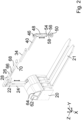
- a mobile handling device 10 with an industrial truck 12 designed as a forklift is shown.
- the forklift 12 has a handling fork 14 with two tines 16.
- the handling device 10 is designed to be connected to or attached to the forklift 12 or to a lifting truck.
- a coordinate system with the axes X, Y and Z is also shown.
- the forklift 12 is moved along an insertion direction 18, which runs in the positive X-direction, to attach the handling device 10.
- the handling fork 14 is located inside or underneath the handling device 10 and is then raised in the positive Z direction.
- the handling fork 14 is lowered in the negative Z direction so that the handling device 10 stands on the ground.
- the handling fork 14 is moved against the insertion direction 18.
- the mobile handling device 10 comprises, as shown in particular in Fig. 2 can be seen a base housing 20 with two tine holders 21 extending along the X-axis.
- the handling device 10 comprises a support 24 which extends along a support axis 22 which is vertical when the handling device 10 is operated as intended.
- the support 24 is designed as a column which is telescopic and therefore height-adjustable.
- a boom 26 is arranged on the support 24.
- the boom 26 comprises a first cantilever member 28 which is fastened to the support 24 in a rotationally and displacement-proof manner and which extends in a first cantilever plane 30 along a first cantilever direction 32.
- the boom 26 further comprises a second cantilever member 34 which is mounted on the first cantilever member 28 by means of a first pivot joint 36 so as to be pivotable about a first axis of rotation 37 and which extends in a second cantilever plane 38.
- the boom 26 further comprises a third cantilever member 40, which is pivotable about a second axis of rotation 43 by means of a second pivot joint 42.
- the second cantilever member 34 is mounted and extends in a third cantilever plane 44.
- the cantilever members 28, 34, 40 and the swivel joints 36, 42 are designed such that the first cantilever plane 30 is arranged above the second cantilever plane 38 and the third cantilever plane 44, that the second cantilever plane 38 is arranged above the third cantilever plane 44 and that the first cantilever plane 30, the second cantilever plane 38 and the third cantilever plane 44 run parallel to one another.
- Fig. 2 , 3a, 3b the mobility of the support 24 and the boom 26 is indicated by means of the double-sided arrows.
- a connecting section 46 for coupling a lifting tool 48 is provided on the third cantilever member 40.
- the lifting tool 48 is designed as a controllable hose lifter.
- a controllable suction gripper 50 for fixing objects 52 is indirectly arranged on the lifting tool 48 in such a way that the suction gripper 50 and an object 52 fixed thereby can be raised and lowered.
- an operating device 54 is provided for operating the handling device 10 by an operator.
- the operating device 54 shown comprises a holding section 56 that can be grasped by the operator and six operating elements 58.
- the holding section 56 is designed as a grippable handle bar that extends essentially vertically and has an elliptical shape in cross section.
- the holding section 56 can be grasped by the operator with one hand.
- the operating elements 58 are arranged on the operating device 54 in such a way that the The operator can operate the operating elements 58 when holding the holding section 56.
- the six operating elements 58 are each designed as a control button, so that the operator can operate the operating elements 58 by applying pressure along an actuation direction 60 using a finger and/or a thumb.
- the actuation direction 60 is essentially transverse to the support axis 22.
- the handling device 10 comprises a controllable vacuum generator 62 and a controllable drive device 64.
- the lifting tool 48 and the suction gripper 50 can be driven by means of vacuum.
- the vacuum generator 62 is designed as a vacuum pump and for providing the vacuum.
- the vacuum pump 62 is preferably arranged in the base housing 20.
- the handling device 10 comprises within the base housing 20, the support 24 and the boom 26 a controllable valve device 66 assigned to the operating device 54 with valves (not shown) for directing the vacuum.
- the drive device 64 interacts with the support 24 and with the cantilever members 28, 34, 40, so that the drive device 64 drives the support 24 for height adjustment and the cantilever members 28, 34, 40 for pivoting.
- the drive device 64 can move the support 24 and the boom 26 independently after actuating a control element 58 or can assist the operator in guiding the support 24 and the boom 26 so that the movement requires only a small amount of effort from the operator.
- Drive device 64 is preferably arranged in the base housing 20 or on the boom 26.
- the handling device 10 also comprises an internal pressure control system 68 and an internal data control system 70, which are arranged in the hollow support 24 and in the hollow boom 26.
- the pressure control system 68 fluidically connects the vacuum pump 62 to the lifting tool 48 and to the suction gripper 50.
- the data control system 70 connects the operating device 54 to the vacuum pump 62 and the drive device 64 by means of signals.
- the operating device 54 is designed such that the operator can actuate the operating elements 58 when holding the holding section 56.
- the operating elements 58 can be used to control the vacuum pump 62, the drive device 64 and the valve device 66 as well as peripheral devices that interact with the handling device 10 and are provided in the vicinity of the handling device 10. Consequently, the operating device is designed such that the operating elements 58 can be used to switch the handling device 10, in particular the vacuum pump 62 and the drive device 64, on and off, the support 24 can be adjusted in height, the cantilever members 28, 34, 40 can be pivoted by more than 360° and the lifting tool 48 can be compressed and expanded parallel to the support axis 22.
- the operating device 54 is designed such that the operating elements 58 can be used to Suction gripper 50 and thus a fixed object 52 can be raised and lowered and a negative pressure can be generated in the suction gripper 50 to fix the object 52. Furthermore, the operating device 54 is designed so that the power of the negative pressure generator 62 and the drive device 64 can be adjusted by means of the operating elements 58 and the valves of the valve device 66 can be opened and closed.
Landscapes
- Engineering & Computer Science (AREA)
- Transportation (AREA)
- Structural Engineering (AREA)
- Mechanical Engineering (AREA)
- Civil Engineering (AREA)
- Life Sciences & Earth Sciences (AREA)
- Geology (AREA)
- Forklifts And Lifting Vehicles (AREA)
Claims (10)
- Dispositif de manipulation (10) comportant un support (24) s'étendant le long d'un axe de support vertical (22),comportant un bras (26, 28, 34, 40) disposé sur le support (24),comportant un outil de levage (48), en particulier un équipement de levage à tube, pouvant être commandé et disposé sur le bras (26, 28, 34, 40),comportant un moyen de préhension (50) pouvant être commandé permettant de fixer des objets (52), en particulier des pinces aspirantes, lequel est disposé sur l'outil de levage (48) de telle sorte que le moyen de préhension (50) et un objet (52) fixé avec celui-ci peuvent être soulevés et abaissés,dans lequel un appareil de manœuvre (54) permettant la manœuvre du dispositif de manipulation (10) par un opérateur, comportant une section de maintien (56) pouvant être saisie par l'opérateur et comportant au moins un élément de manœuvre (58), est prévu,dans lequel la section de maintien (56) et l'au moins un élément de manœuvre (58) sont disposés sur le moyen de préhension (50) ou sur l'outil de levage (48) ou entre le moyen de préhension (50) et l'outil de levage (48),caractérisé en ce que le support (24) est réalisé sous forme de colonne qui est télescopique et ainsi réglable en hauteur, en ce qu'au moins un appareil d'entraînement (64) pouvant être commandé est prévu pour le réglage en hauteur du support (24) et en ce que l'appareil de manœuvre (54) est réalisé de telle sorte que le moyen de préhension (50), l'outil de levage (48) et l'appareil d'entraînement (64) peuvent être commandés au moyen de l'au moins un élément de manœuvre (58) pour le réglage en hauteur du support (24).
- Dispositif de manipulation (10) selon la revendication 1, dans lequel la section de maintien (56) et l'au moins un élément de manœuvre (58) sont réalisés de telle sorte que l'opérateur peut actionner l'au moins un élément de manœuvre (58) lors du maintien de la section de maintien (56).
- Dispositif de manipulation (10) selon la revendication 1 ou 2, dans lequel la section de maintien (56) est réalisée sous forme de poignée de maintien (56) pouvant être saisie à une main par l'opérateur, et en ce que l'au moins un élément de manœuvre (58) est réalisé et positionné de telle sorte que l'opérateur peut simultanément saisir la poignée de maintien (56) à une main et actionner l'élément de manœuvre (58).
- Dispositif de manipulation (10) selon l'une des revendications précédentes, dans lequel la poignée de maintien (56) est réalisée sous forme de barre de préhension (56) saisissable qui s'étend sensiblement verticalement lorsque le dispositif de manipulation (10) est en fonctionnement.
- Dispositif de manipulation (10) selon l'une des revendications précédentes, dans lequel le bras (26, 28, 34, 40) est mobile en rotation et/ou en translation par rapport au support (24), dans lequel l'appareil d'entraînement (64) pouvant être commandé est réalisé pour déplacer le bras (26, 28, 34, 40), et dans lequel l'appareil de manœuvre (54) est réalisé de telle sorte que l'appareil d'entraînement (64) peut être commandé au moyen de l'au moins un élément de manœuvre (58) pour le déplacement du bras (26, 28, 34, 40).
- Dispositif de manipulation (10) selon l'une des revendications précédentes, dans lequel l'appareil de manœuvre (54) est réalisé de telle sorte que le moyen de préhension (50) peut être commandé pour fixer un objet (52) et pour relâcher l'objet (52) au moyen de l'au moins un élément de manœuvre (58).
- Dispositif de manipulation (10) selon l'une des revendications précédentes, dans lequel l'appareil de manœuvre (54) est réalisé de telle sorte que l'outil de levage (48) peut être commandé pour soulever et abaisser le moyen de préhension (50) au moyen de l'au moins un élément de manœuvre (58).
- Dispositif de manipulation (10) selon l'une des revendications précédentes, dans lequel l'outil de levage (48) peut être entraîné au moyen d'une dépression, dans lequel le dispositif de manipulation (10) comprend un générateur de dépression (62) pouvant être commandé, en particulier une pompe à dépression, pour la fourniture de la dépression et un appareil à soupape (66) pouvant être commandé pour la commande de l'outil de levage, dans lequel l'appareil de manœuvre (54) est réalisé de telle sorte que le générateur de dépression (62) et l'appareil à soupape (66) peuvent être commandés au moyen de l'au moins un élément de manœuvre (58).
- Dispositif de manipulation (10) selon l'une des revendications précédentes, dans lequel l'appareil de manœuvre (54) est réalisé de telle sorte qu'un appareil de périphérie, en particulier une bande transporteuse, un robot et/ou une station de production, coopérant avec le dispositif de manipulation (10) ou prévu dans l'environnement du dispositif de manipulation (10), peut être commandé au moyen de l'au moins un élément de manœuvre (58).
- Dispositif de manipulation (10) selon l'une des revendications précédentes, réalisé sous forme de dispositif de manipulation (10) mobile destiné à être disposé sur un chariot de manutention (12), en particulier un préparateur de commandes, un chariot élévateur ou une empileuse à fourche.
Applications Claiming Priority (1)
| Application Number | Priority Date | Filing Date | Title |
|---|---|---|---|
| DE102021109902.1A DE102021109902B4 (de) | 2021-04-20 | 2021-04-20 | Handhabungsvorrichtung mit Steuerung |
Publications (2)
| Publication Number | Publication Date |
|---|---|
| EP4079674A1 EP4079674A1 (fr) | 2022-10-26 |
| EP4079674B1 true EP4079674B1 (fr) | 2025-02-19 |
Family
ID=81595690
Family Applications (1)
| Application Number | Title | Priority Date | Filing Date |
|---|---|---|---|
| EP22168480.6A Active EP4079674B1 (fr) | 2021-04-20 | 2022-04-14 | Dispositif de manutention à commande |
Country Status (2)
| Country | Link |
|---|---|
| EP (1) | EP4079674B1 (fr) |
| DE (1) | DE102021109902B4 (fr) |
Citations (2)
| Publication number | Priority date | Publication date | Assignee | Title |
|---|---|---|---|---|
| JP2011119556A (ja) * | 2009-12-07 | 2011-06-16 | Yaskawa Electric Corp | 水平多関節ロボットおよびそれを備えた搬送装置 |
| DE102018121726A1 (de) * | 2018-09-06 | 2020-03-12 | Jungheinrich Ag | Flurförderzeug umfassend eine Kommissioniervorrichtung |
Family Cites Families (8)
| Publication number | Priority date | Publication date | Assignee | Title |
|---|---|---|---|---|
| JPH0787667B2 (ja) | 1987-04-30 | 1995-09-20 | 三菱電機株式会社 | 回路しや断器 |
| US5915673A (en) * | 1996-03-27 | 1999-06-29 | Kazerooni; Homayoon | Pneumatic human power amplifer module |
| US6386513B1 (en) * | 1999-05-13 | 2002-05-14 | Hamayoon Kazerooni | Human power amplifier for lifting load including apparatus for preventing slack in lifting cable |
| ES2351906B1 (es) | 2009-05-29 | 2011-12-28 | Aranguren Comercial Del Embalaje S.L. | Estructura soporte para unir a una traspaleta eléctrica un dispositivo funcional. |
| FR3026733B1 (fr) | 2014-10-01 | 2016-11-18 | Dm Investissements | Engin de manutention. |
| DE102015112125A1 (de) | 2015-07-24 | 2017-01-26 | Strödter Handhabungstechnik GmbH | Kommissioniergerät |
| CN209989023U (zh) | 2019-04-30 | 2020-01-24 | 微可为(厦门)真空科技有限公司 | 一种带有吸吊的电动叉车 |
| DE202020104055U1 (de) | 2020-02-05 | 2020-08-14 | BARRUS GmbH | Manipulator zum Anordnen an einem Fahrzeug |
-
2021
- 2021-04-20 DE DE102021109902.1A patent/DE102021109902B4/de active Active
-
2022
- 2022-04-14 EP EP22168480.6A patent/EP4079674B1/fr active Active
Patent Citations (2)
| Publication number | Priority date | Publication date | Assignee | Title |
|---|---|---|---|---|
| JP2011119556A (ja) * | 2009-12-07 | 2011-06-16 | Yaskawa Electric Corp | 水平多関節ロボットおよびそれを備えた搬送装置 |
| DE102018121726A1 (de) * | 2018-09-06 | 2020-03-12 | Jungheinrich Ag | Flurförderzeug umfassend eine Kommissioniervorrichtung |
Also Published As
| Publication number | Publication date |
|---|---|
| DE102021109902B4 (de) | 2025-03-27 |
| EP4079674A1 (fr) | 2022-10-26 |
| DE102021109902A1 (de) | 2022-10-20 |
Similar Documents
| Publication | Publication Date | Title |
|---|---|---|
| DE3788286T2 (de) | Handmechanismus. | |
| EP3020513B1 (fr) | Procédé de maniement et/ou de manipulation des articles comme des récipients ou des marchandises au détail | |
| DE102015115866B4 (de) | Einrichtung zum Umpacken von zu Packungseinheiten zusammengefassten Stückgütern | |
| EP3221092B1 (fr) | Dispositif et procédé de manipulation d'articles tels que des groupements d'articles, des colis ou analogues | |
| DE102014223389A1 (de) | Vorrichtung und Verfahren zur Handhabung von Artikeln wie Gebinde, Stückgüter oder dergleichen | |
| DE102016220643A1 (de) | Robotergreifer mit beweglichen Hilfssaugelementen | |
| EP3365139B1 (fr) | Robot à cinématique parallèle et procédé de manipulation dudit robot | |
| DE3622923C2 (de) | Manipulator, insbesondere zur Handhabung von Blechen bei Abkantvorgängen | |
| DE602005006006T2 (de) | Handhabungseinheit zum palettieren | |
| EP3173192B1 (fr) | Dispositif et procédé pour le contrôle coordonné d'au moins deux robots à cinématique parallèle | |
| EP4116046B1 (fr) | Effecteur terminal pourvu de préhenseurs d'article et préhenseur de porte-charge | |
| EP4015158B1 (fr) | Dispositif de manutention permettant de manipuler des objets | |
| EP1116677B1 (fr) | Dispositif pour le transport et le positionnement de rames de matériau en feuille empilé | |
| EP3221093B1 (fr) | Dispositif et procédé de manutention et/ou de manipulation d'articles tels que des ensembles d'articles ou des colis | |
| EP4079674B1 (fr) | Dispositif de manutention à commande | |
| EP1623773B1 (fr) | Robot articulé | |
| DE102015223528A1 (de) | Parallelkinematik-Roboter mit mindestens einer Entlastungseinrichtung und Verfahren zum Betreiben eines Parallelkinematik-Roboters | |
| EP3623103A1 (fr) | Dispositif de manipulation d'un outil d'une machine-outil ou d'un robot | |
| EP4349537A1 (fr) | Dispositif de manipulation | |
| WO2017029012A1 (fr) | Dispositif et procédé de manutention et/ou de manipulation d'articles tels que des conteneurs ou des colis | |
| EP4247598B1 (fr) | Dispositif de préhension et manipulateur doté d'un dispositif de préhension | |
| DE19847502A1 (de) | Bewegungseinrichtung zur Bewegung eines Endeffektors | |
| DE10162047C1 (de) | Platinenhandlinggerät, insbesondere zum Einlegen von Blechplatinen in eine Presse | |
| DE4244047A1 (de) | Antriebseinheit | |
| EP4553014A1 (fr) | Tête de préhension et procédé de manipulation de découpes d'emballage |
Legal Events
| Date | Code | Title | Description |
|---|---|---|---|
| PUAI | Public reference made under article 153(3) epc to a published international application that has entered the european phase |
Free format text: ORIGINAL CODE: 0009012 |
|
| STAA | Information on the status of an ep patent application or granted ep patent |
Free format text: STATUS: THE APPLICATION HAS BEEN PUBLISHED |
|
| AK | Designated contracting states |
Kind code of ref document: A1 Designated state(s): AL AT BE BG CH CY CZ DE DK EE ES FI FR GB GR HR HU IE IS IT LI LT LU LV MC MK MT NL NO PL PT RO RS SE SI SK SM TR |
|
| RIN1 | Information on inventor provided before grant (corrected) |
Inventor name: KATZ, SANDRO Inventor name: BURT, HANS Inventor name: KOHLER, JONATHAN Inventor name: BECK, STEFFEN Inventor name: MUELLER, DANIEL Inventor name: DREHER, STEFAN |
|
| STAA | Information on the status of an ep patent application or granted ep patent |
Free format text: STATUS: REQUEST FOR EXAMINATION WAS MADE |
|
| 17P | Request for examination filed |
Effective date: 20230329 |
|
| RBV | Designated contracting states (corrected) |
Designated state(s): AL AT BE BG CH CY CZ DE DK EE ES FI FR GB GR HR HU IE IS IT LI LT LU LV MC MK MT NL NO PL PT RO RS SE SI SK SM TR |
|
| STAA | Information on the status of an ep patent application or granted ep patent |
Free format text: STATUS: EXAMINATION IS IN PROGRESS |
|
| 17Q | First examination report despatched |
Effective date: 20231214 |
|
| GRAP | Despatch of communication of intention to grant a patent |
Free format text: ORIGINAL CODE: EPIDOSNIGR1 |
|
| STAA | Information on the status of an ep patent application or granted ep patent |
Free format text: STATUS: GRANT OF PATENT IS INTENDED |
|
| INTG | Intention to grant announced |
Effective date: 20240927 |
|
| GRAS | Grant fee paid |
Free format text: ORIGINAL CODE: EPIDOSNIGR3 |
|
| GRAA | (expected) grant |
Free format text: ORIGINAL CODE: 0009210 |
|
| STAA | Information on the status of an ep patent application or granted ep patent |
Free format text: STATUS: THE PATENT HAS BEEN GRANTED |
|
| AK | Designated contracting states |
Kind code of ref document: B1 Designated state(s): AL AT BE BG CH CY CZ DE DK EE ES FI FR GB GR HR HU IE IS IT LI LT LU LV MC MK MT NL NO PL PT RO RS SE SI SK SM TR |
|
| REG | Reference to a national code |
Ref country code: GB Ref legal event code: FG4D Free format text: NOT ENGLISH |
|
| REG | Reference to a national code |
Ref country code: CH Ref legal event code: EP |
|
| REG | Reference to a national code |
Ref country code: IE Ref legal event code: FG4D Free format text: LANGUAGE OF EP DOCUMENT: GERMAN |
|
| REG | Reference to a national code |
Ref country code: DE Ref legal event code: R096 Ref document number: 502022002910 Country of ref document: DE |
|
| REG | Reference to a national code |
Ref country code: SE Ref legal event code: TRGR |
|
| REG | Reference to a national code |
Ref country code: NL Ref legal event code: MP Effective date: 20250219 |
|
| PG25 | Lapsed in a contracting state [announced via postgrant information from national office to epo] |
Ref country code: RS Free format text: LAPSE BECAUSE OF FAILURE TO SUBMIT A TRANSLATION OF THE DESCRIPTION OR TO PAY THE FEE WITHIN THE PRESCRIBED TIME-LIMIT Effective date: 20250519 |
|
| PG25 | Lapsed in a contracting state [announced via postgrant information from national office to epo] |
Ref country code: FI Free format text: LAPSE BECAUSE OF FAILURE TO SUBMIT A TRANSLATION OF THE DESCRIPTION OR TO PAY THE FEE WITHIN THE PRESCRIBED TIME-LIMIT Effective date: 20250219 |
|
| PG25 | Lapsed in a contracting state [announced via postgrant information from national office to epo] |
Ref country code: PL Free format text: LAPSE BECAUSE OF FAILURE TO SUBMIT A TRANSLATION OF THE DESCRIPTION OR TO PAY THE FEE WITHIN THE PRESCRIBED TIME-LIMIT Effective date: 20250219 |
|
| PGFP | Annual fee paid to national office [announced via postgrant information from national office to epo] |
Ref country code: DE Payment date: 20250611 Year of fee payment: 4 |
|
| PG25 | Lapsed in a contracting state [announced via postgrant information from national office to epo] |
Ref country code: ES Free format text: LAPSE BECAUSE OF FAILURE TO SUBMIT A TRANSLATION OF THE DESCRIPTION OR TO PAY THE FEE WITHIN THE PRESCRIBED TIME-LIMIT Effective date: 20250219 |
|
| REG | Reference to a national code |
Ref country code: LT Ref legal event code: MG9D |
|
| PG25 | Lapsed in a contracting state [announced via postgrant information from national office to epo] |
Ref country code: IS Free format text: LAPSE BECAUSE OF FAILURE TO SUBMIT A TRANSLATION OF THE DESCRIPTION OR TO PAY THE FEE WITHIN THE PRESCRIBED TIME-LIMIT Effective date: 20250619 Ref country code: NO Free format text: LAPSE BECAUSE OF FAILURE TO SUBMIT A TRANSLATION OF THE DESCRIPTION OR TO PAY THE FEE WITHIN THE PRESCRIBED TIME-LIMIT Effective date: 20250519 |
|
| PG25 | Lapsed in a contracting state [announced via postgrant information from national office to epo] |
Ref country code: NL Free format text: LAPSE BECAUSE OF FAILURE TO SUBMIT A TRANSLATION OF THE DESCRIPTION OR TO PAY THE FEE WITHIN THE PRESCRIBED TIME-LIMIT Effective date: 20250219 |
|
| PG25 | Lapsed in a contracting state [announced via postgrant information from national office to epo] |
Ref country code: HR Free format text: LAPSE BECAUSE OF FAILURE TO SUBMIT A TRANSLATION OF THE DESCRIPTION OR TO PAY THE FEE WITHIN THE PRESCRIBED TIME-LIMIT Effective date: 20250219 |
|
| PG25 | Lapsed in a contracting state [announced via postgrant information from national office to epo] |
Ref country code: LV Free format text: LAPSE BECAUSE OF FAILURE TO SUBMIT A TRANSLATION OF THE DESCRIPTION OR TO PAY THE FEE WITHIN THE PRESCRIBED TIME-LIMIT Effective date: 20250219 Ref country code: PT Free format text: LAPSE BECAUSE OF FAILURE TO SUBMIT A TRANSLATION OF THE DESCRIPTION OR TO PAY THE FEE WITHIN THE PRESCRIBED TIME-LIMIT Effective date: 20250620 |
|
| PGFP | Annual fee paid to national office [announced via postgrant information from national office to epo] |
Ref country code: FR Payment date: 20250425 Year of fee payment: 4 |
|
| PG25 | Lapsed in a contracting state [announced via postgrant information from national office to epo] |
Ref country code: GR Free format text: LAPSE BECAUSE OF FAILURE TO SUBMIT A TRANSLATION OF THE DESCRIPTION OR TO PAY THE FEE WITHIN THE PRESCRIBED TIME-LIMIT Effective date: 20250520 Ref country code: BG Free format text: LAPSE BECAUSE OF FAILURE TO SUBMIT A TRANSLATION OF THE DESCRIPTION OR TO PAY THE FEE WITHIN THE PRESCRIBED TIME-LIMIT Effective date: 20250219 |
|
| PGFP | Annual fee paid to national office [announced via postgrant information from national office to epo] |
Ref country code: AT Payment date: 20250721 Year of fee payment: 4 |
|
| PGFP | Annual fee paid to national office [announced via postgrant information from national office to epo] |
Ref country code: SE Payment date: 20250417 Year of fee payment: 4 |
|
| PG25 | Lapsed in a contracting state [announced via postgrant information from national office to epo] |
Ref country code: SM Free format text: LAPSE BECAUSE OF FAILURE TO SUBMIT A TRANSLATION OF THE DESCRIPTION OR TO PAY THE FEE WITHIN THE PRESCRIBED TIME-LIMIT Effective date: 20250219 |
|
| PG25 | Lapsed in a contracting state [announced via postgrant information from national office to epo] |
Ref country code: DK Free format text: LAPSE BECAUSE OF FAILURE TO SUBMIT A TRANSLATION OF THE DESCRIPTION OR TO PAY THE FEE WITHIN THE PRESCRIBED TIME-LIMIT Effective date: 20250219 |
|
| PG25 | Lapsed in a contracting state [announced via postgrant information from national office to epo] |
Ref country code: IT Free format text: LAPSE BECAUSE OF FAILURE TO SUBMIT A TRANSLATION OF THE DESCRIPTION OR TO PAY THE FEE WITHIN THE PRESCRIBED TIME-LIMIT Effective date: 20250219 |
|
| PG25 | Lapsed in a contracting state [announced via postgrant information from national office to epo] |
Ref country code: EE Free format text: LAPSE BECAUSE OF FAILURE TO SUBMIT A TRANSLATION OF THE DESCRIPTION OR TO PAY THE FEE WITHIN THE PRESCRIBED TIME-LIMIT Effective date: 20250219 Ref country code: CZ Free format text: LAPSE BECAUSE OF FAILURE TO SUBMIT A TRANSLATION OF THE DESCRIPTION OR TO PAY THE FEE WITHIN THE PRESCRIBED TIME-LIMIT Effective date: 20250219 |
|
| PG25 | Lapsed in a contracting state [announced via postgrant information from national office to epo] |
Ref country code: RO Free format text: LAPSE BECAUSE OF FAILURE TO SUBMIT A TRANSLATION OF THE DESCRIPTION OR TO PAY THE FEE WITHIN THE PRESCRIBED TIME-LIMIT Effective date: 20250219 |
|
| PG25 | Lapsed in a contracting state [announced via postgrant information from national office to epo] |
Ref country code: SK Free format text: LAPSE BECAUSE OF FAILURE TO SUBMIT A TRANSLATION OF THE DESCRIPTION OR TO PAY THE FEE WITHIN THE PRESCRIBED TIME-LIMIT Effective date: 20250219 |
|
| REG | Reference to a national code |
Ref country code: DE Ref legal event code: R097 Ref document number: 502022002910 Country of ref document: DE |
|
| REG | Reference to a national code |
Ref country code: CH Ref legal event code: H13 Free format text: ST27 STATUS EVENT CODE: U-0-0-H10-H13 (AS PROVIDED BY THE NATIONAL OFFICE) Effective date: 20251125 |
|
| PG25 | Lapsed in a contracting state [announced via postgrant information from national office to epo] |
Ref country code: LU Free format text: LAPSE BECAUSE OF NON-PAYMENT OF DUE FEES Effective date: 20250414 |
|
| PG25 | Lapsed in a contracting state [announced via postgrant information from national office to epo] |
Ref country code: MC Free format text: LAPSE BECAUSE OF FAILURE TO SUBMIT A TRANSLATION OF THE DESCRIPTION OR TO PAY THE FEE WITHIN THE PRESCRIBED TIME-LIMIT Effective date: 20250219 |
|
| PLBE | No opposition filed within time limit |
Free format text: ORIGINAL CODE: 0009261 |
|
| STAA | Information on the status of an ep patent application or granted ep patent |
Free format text: STATUS: NO OPPOSITION FILED WITHIN TIME LIMIT |
|
| REG | Reference to a national code |
Ref country code: BE Ref legal event code: MM Effective date: 20250430 |
|
| PG25 | Lapsed in a contracting state [announced via postgrant information from national office to epo] |
Ref country code: BE Free format text: LAPSE BECAUSE OF NON-PAYMENT OF DUE FEES Effective date: 20250430 |
|
| PG25 | Lapsed in a contracting state [announced via postgrant information from national office to epo] |
Ref country code: CH Free format text: LAPSE BECAUSE OF NON-PAYMENT OF DUE FEES Effective date: 20250430 |
|
| 26N | No opposition filed |
Effective date: 20251120 |
|
| PG25 | Lapsed in a contracting state [announced via postgrant information from national office to epo] |
Ref country code: IE Free format text: LAPSE BECAUSE OF NON-PAYMENT OF DUE FEES Effective date: 20250414 |