EP4553014A1 - Tête de préhension et procédé de manipulation de découpes d'emballage - Google Patents
Tête de préhension et procédé de manipulation de découpes d'emballage Download PDFInfo
- Publication number
- EP4553014A1 EP4553014A1 EP24207104.1A EP24207104A EP4553014A1 EP 4553014 A1 EP4553014 A1 EP 4553014A1 EP 24207104 A EP24207104 A EP 24207104A EP 4553014 A1 EP4553014 A1 EP 4553014A1
- Authority
- EP
- European Patent Office
- Prior art keywords
- packaging blanks
- gripper head
- packaging
- gripping unit
- blanks
- Prior art date
- Legal status (The legal status is an assumption and is not a legal conclusion. Google has not performed a legal analysis and makes no representation as to the accuracy of the status listed.)
- Pending
Links
Images






Classifications
-
- B—PERFORMING OPERATIONS; TRANSPORTING
- B65—CONVEYING; PACKING; STORING; HANDLING THIN OR FILAMENTARY MATERIAL
- B65G—TRANSPORT OR STORAGE DEVICES, e.g. CONVEYORS FOR LOADING OR TIPPING, SHOP CONVEYOR SYSTEMS OR PNEUMATIC TUBE CONVEYORS
- B65G59/00—De-stacking of articles
- B65G59/02—De-stacking from the top of the stack
- B65G59/023—De-stacking from the top of the stack by means insertable between the stacked articles or layers
-
- B—PERFORMING OPERATIONS; TRANSPORTING
- B65—CONVEYING; PACKING; STORING; HANDLING THIN OR FILAMENTARY MATERIAL
- B65G—TRANSPORT OR STORAGE DEVICES, e.g. CONVEYORS FOR LOADING OR TIPPING, SHOP CONVEYOR SYSTEMS OR PNEUMATIC TUBE CONVEYORS
- B65G47/00—Article or material-handling devices associated with conveyors; Methods employing such devices
- B65G47/74—Feeding, transfer, or discharging devices of particular kinds or types
- B65G47/90—Devices for picking-up and depositing articles or materials
- B65G47/91—Devices for picking-up and depositing articles or materials incorporating pneumatic, e.g. suction, grippers
-
- B—PERFORMING OPERATIONS; TRANSPORTING
- B25—HAND TOOLS; PORTABLE POWER-DRIVEN TOOLS; MANIPULATORS
- B25J—MANIPULATORS; CHAMBERS PROVIDED WITH MANIPULATION DEVICES
- B25J15/00—Gripping heads and other end effectors
- B25J15/0014—Gripping heads and other end effectors having fork, comb or plate shaped means for engaging the lower surface on a object to be transported
-
- B—PERFORMING OPERATIONS; TRANSPORTING
- B25—HAND TOOLS; PORTABLE POWER-DRIVEN TOOLS; MANIPULATORS
- B25J—MANIPULATORS; CHAMBERS PROVIDED WITH MANIPULATION DEVICES
- B25J15/00—Gripping heads and other end effectors
- B25J15/06—Gripping heads and other end effectors with vacuum or magnetic holding means
- B25J15/0616—Gripping heads and other end effectors with vacuum or magnetic holding means with vacuum
-
- B—PERFORMING OPERATIONS; TRANSPORTING
- B65—CONVEYING; PACKING; STORING; HANDLING THIN OR FILAMENTARY MATERIAL
- B65B—MACHINES, APPARATUS OR DEVICES FOR, OR METHODS OF, PACKAGING ARTICLES OR MATERIALS; UNPACKING
- B65B43/00—Forming, feeding, opening or setting-up containers or receptacles in association with packaging
- B65B43/12—Feeding flexible bags or carton blanks in flat or collapsed state; Feeding flat bags connected to form a series or chain
- B65B43/14—Feeding individual bags or carton blanks from piles or magazines
- B65B43/16—Feeding individual bags or carton blanks from piles or magazines by grippers
- B65B43/18—Feeding individual bags or carton blanks from piles or magazines by grippers by suction-operated grippers
- B65B43/185—Feeding individual bags or carton blanks from piles or magazines by grippers by suction-operated grippers specially adapted for carton blanks
-
- B—PERFORMING OPERATIONS; TRANSPORTING
- B65—CONVEYING; PACKING; STORING; HANDLING THIN OR FILAMENTARY MATERIAL
- B65G—TRANSPORT OR STORAGE DEVICES, e.g. CONVEYORS FOR LOADING OR TIPPING, SHOP CONVEYOR SYSTEMS OR PNEUMATIC TUBE CONVEYORS
- B65G47/00—Article or material-handling devices associated with conveyors; Methods employing such devices
- B65G47/74—Feeding, transfer, or discharging devices of particular kinds or types
- B65G47/90—Devices for picking-up and depositing articles or materials
-
- B—PERFORMING OPERATIONS; TRANSPORTING
- B65—CONVEYING; PACKING; STORING; HANDLING THIN OR FILAMENTARY MATERIAL
- B65G—TRANSPORT OR STORAGE DEVICES, e.g. CONVEYORS FOR LOADING OR TIPPING, SHOP CONVEYOR SYSTEMS OR PNEUMATIC TUBE CONVEYORS
- B65G59/00—De-stacking of articles
- B65G59/005—De-stacking of articles by using insertions or spacers between the stacked layers
-
- B—PERFORMING OPERATIONS; TRANSPORTING
- B65—CONVEYING; PACKING; STORING; HANDLING THIN OR FILAMENTARY MATERIAL
- B65H—HANDLING THIN OR FILAMENTARY MATERIAL, e.g. SHEETS, WEBS, CABLES
- B65H3/00—Separating articles from piles
- B65H3/08—Separating articles from piles using pneumatic force
- B65H3/0808—Suction grippers
- B65H3/0883—Construction of suction grippers or their holding devices
-
- B—PERFORMING OPERATIONS; TRANSPORTING
- B65—CONVEYING; PACKING; STORING; HANDLING THIN OR FILAMENTARY MATERIAL
- B65H—HANDLING THIN OR FILAMENTARY MATERIAL, e.g. SHEETS, WEBS, CABLES
- B65H3/00—Separating articles from piles
- B65H3/32—Separating articles from piles by elements, e.g. fingers, plates, rollers, inserted or traversed between articles to be separated and remainder of the pile
- B65H3/322—Separating articles from piles by elements, e.g. fingers, plates, rollers, inserted or traversed between articles to be separated and remainder of the pile for separating a part of the pile, i.e. several articles at once
-
- B—PERFORMING OPERATIONS; TRANSPORTING
- B65—CONVEYING; PACKING; STORING; HANDLING THIN OR FILAMENTARY MATERIAL
- B65G—TRANSPORT OR STORAGE DEVICES, e.g. CONVEYORS FOR LOADING OR TIPPING, SHOP CONVEYOR SYSTEMS OR PNEUMATIC TUBE CONVEYORS
- B65G2201/00—Indexing codes relating to handling devices, e.g. conveyors, characterised by the type of product or load being conveyed or handled
- B65G2201/02—Articles
- B65G2201/0235—Containers
Definitions
- the present invention relates to a gripper head and a method for handling packaging blanks.
- the invention also relates to a packaging system.
- Such a destination could, for example, be a packaging machine that packages items with the respective packaging blanks.
- a packaging machine can already accommodate a large quantity of packaging blanks, which it then uses to package items.
- new packaging blanks are regularly transferred to the packaging machine.
- manipulators are used for this purpose. These manipulators can successively remove several packaging blanks from a stack using a gripper head and then transfer them to the respective packaging machine.
- Removing packaging blanks using a gripper head can be problematic, as the individual packaging blanks stacked on top of each other cannot be adequately clamped to subsequently transport them to the packaging machine. Even with a clamped reception, it cannot be completely ruled out that individual packaging blanks in the stack will be bent or damaged by the gripper head during reception. It also cannot be completely ruled out that flat packaging blanks will unintentionally detach from the gripper head after they have been inadequately clamped by the respective gripper head.
- manipulators known from the state of the art which receive packaging blanks from a stack and transfer them to a packaging machine, often have little flexibility in handling packaging blanks with different formats.
- a The gripper head of the respective manipulator must be exchanged if packaging blanks with different formats are to be received consecutively from a pallet and transferred to a packaging machine.
- One object of the invention can therefore be seen in providing a method by which flat packaging blanks can be picked up and handled from a stack safely and without or with a reduced risk of damage. Furthermore, a method is to be provided by which packaging blanks of different formats can be received and handled easily and simply.
- the invention relates to a gripper head for handling packaging blanks.
- the packaging blanks can, for example, be packaging blanks that are formed at least partially or even entirely from cellulose-containing material.
- the packaging blanks can be formed at least partially or even entirely from plastic. It is also conceivable for the packaging blanks to be formed at least partially or even entirely from aluminum.
- the packaging blanks can have tabs that can be folded upwards.
- a respective packaging blank can also be a so-called PAD, which provides a flat support surface for several articles.
- the gripper head comprises an upper gripping unit and a lower gripping unit, each of which is configured to jointly grip multiple packaging blanks from a stack containing a plurality of packaging blanks.
- the upper gripping unit and the lower gripping unit can be configured such that the upper gripping unit and the lower gripping unit can perform a feed movement in which the upper gripping unit and the lower gripping unit reduce their relative distance from one another and thereby jointly grip multiple packaging blanks.
- the gripper head can comprise a frame on which the upper gripping unit and the lower gripping unit are arranged.
- the frame can, in particular, consist of several sheet metal parts welded together.
- the gripper head comprises a separating unit which is designed to lift outer edges of respective packaging blanks intended for clamping gripping relative to packaging blanks remaining on the stack, so that the lower gripping unit can be inserted into the stack of packaging blanks in the region of the raised outer edges.
- the separating unit comprises a linear actuator for lifting the outer edges, which is arranged such that its linear lifting axis is inclined relative to a contact surface formed by the lower gripping unit when the separating unit lifts the outer edges of the respective packaging blanks via the at least one linear actuator.
- the inclination of the lifting axis relative to the contact surface makes it highly likely that packaging blanks will not unintentionally detach from the separating unit when their outer edges are lifted.
- the gripper head can be guided against the respective packaging blanks to be clamped, whereby the respective packaging blanks to be clamped move a piston of the at least one linear actuator along the rectilinear lifting axis, and the outer edges of the respective packaging blanks to be clamped are lifted above the separating unit.
- the gripper head can be designed in such a way that a force with which the piston of the at least one linear actuator clamps the respective the packaging blanks to be received. If the at least one linear actuator is at least one pneumatic cylinder, it may be that a working pressure of the at least one pneumatic cylinder is adjustable via a control and/or regulating device of the gripper head.
- the at least one linear actuator can thus be at least one pneumatic cylinder.
- the invention is not limited to this, so that in further embodiments, the at least one linear actuator can also be, for example, at least one electric linear motor or at least one electromagnetic direct drive.
- the linear lifting axis may be inclined relative to the contact surface at an angle of between 5° and 30°, in particular between 10° and 25°, and preferably between 15° and 20°.
- the linear lifting axis may be inclined relative to the contact surface at an angle of substantially 18°.
- the upper gripping unit can comprise at least two fork tines oriented parallel to one another.
- the upper gripping unit can also be designed as a molded part that cooperates with the lower gripping unit to jointly clamp and grip multiple packaging blanks from a stack.
- the molded part can be, for example, a sheet metal part or another part that provides a flat clamping surface for the multiple packaging blanks to be clamped.
- the lower gripping unit may comprise at least two fork tines oriented parallel to one another.
- the lower gripping unit is designed as a molded part, which cooperates with the upper gripping unit for the joint clamping grip of several packaging blanks from a stack and provides the previously mentioned contact surface for packaging blanks. If the lower gripping unit comprises at least two fork tines oriented parallel to one another, the at least two fork tines oriented parallel to one another can have the previously mentioned contact surface or form the previously mentioned contact surface.
- the lower gripping unit may comprise two outer forks and two inner forks, wherein the two outer forks and/or the two inner forks are adjustable such that the two outer forks can be brought into a common plane with the two inner forks.
- the two outer forks may be adjustable along their respective longitudinal axes and relative to the previously mentioned frame of the gripper head.
- Embodiments have proven successful in which the lower gripping unit comprises at least four fork tines oriented parallel to one another, wherein two inner fork tines of the at least four fork tines oriented parallel to one another are adjustable in such a way that the two inner fork tines can be brought into a first position in which the two inner fork tines are in a common plane with the two outer fork tines and can be brought into a second position in which the two inner fork tines have left this plane.
- the gripper head can comprise at least one actuator, via which the two inner forks can be moved from the first position to the second position. Since the two inner forks and the two outer forks are located in a common plane in the first position, packaging blanks picked up by the gripper head can be carried by both the two inner forks and the two outer forks. In practice, it may be necessary to pick up packaging blanks with small dimensions using the same gripper head.
- the two outer forks may not be necessary to carry such packaging blanks.
- the two inner forks can therefore be in the second position if the two outer forks are not needed to carry the multiple packaging blanks.
- the described embodiment has This provides a high degree of flexibility when picking up and handling packaging blanks with different dimensions.
- the gripper head can comprise at least one fork tine which is designed such that it can be moved into a pallet to pick up a pallet. This makes it easy to handle pallets in addition to packaging blanks.
- the gripper head can comprise at least one clamping and/or gripping element via which the gripper head can hold a pallet.
- the at least one clamping and/or gripping element can be, for example, at least one gripping finger and/or at least one gripping hook.
- the at least one clamping and/or gripping element can also be at least two clamping and/or gripping jaws which can jointly receive a respective pallet in a force-fitting and/or form-fitting manner.
- pallets can be handled in a simple manner in addition to packaging blanks.
- the lower gripping unit may comprise at least four fork tines oriented parallel to one another, wherein two outer fork tines of the at least four fork tines oriented parallel to one another are adjustable via a linear guide of the gripper head such that the two outer fork tines of the at least four fork tines oriented parallel to one another can move along their longitudinal direction.
- the upper gripping unit and/or the lower gripping unit can be arranged on a straight guide, wherein the upper gripping unit and/or the lower gripping unit is/are moved along the straight guide to clamp the respective plurality of packaging blanks.
- a pneumatic cylinder may be assigned to the upper gripping unit, via which the upper gripping unit can be moved along the straight guide.
- An electric linear drive may also be assigned to the upper gripping unit, via which the upper gripping unit can be moved along the straight guide.
- the upper gripping unit is designed to be pivotable in order to clamp the respective multiple packaging blanks.
- the gripping unit can comprise a sheet metal part which is pivotable in such a way that it can be placed on a respective upper packaging blank of the respective plurality of packaging blanks by means of a pivoting movement for clampingly gripping the respective plurality of packaging blanks.
- Embodiments in which the upper gripping unit is designed to be pivotable have proven effective in practice for transferring the upper gripping unit to a defined waiting position.
- the gripper head can be moved very close to a target location, to which the gripper head subsequently transfers the picked-up packaging blanks. Handling, and in particular the transfer of packaging blanks to a specified destination, can thus be further improved if the upper gripping unit is designed to be pivotable.
- the separating unit can be arranged on the lower gripping unit.
- the separation unit may have a carriage on which the at least one linear actuator is arranged, wherein the carriage is movable in a straight line along a guide of the gripper head together with the at least one linear actuator. If the separation unit is arranged on the lower gripping unit, the guide may be provided by the lower gripping unit of the gripper head. If the separation unit is arranged on the upper gripping unit, the guide may be provided by the upper gripping unit of the gripper head.
- the gripper head may have at least one actuator and a toothed belt or a spindle, wherein the carriage can be moved in a straight line by means of the at least one actuator via the toothed belt or via the spindle along the guide together with the at least one linear actuator.
- the separating unit has a stop that can be moved via the linear actuator and is used to align the outer edges of the The stop can form a contact surface for the respective packaging blanks intended for clamping.
- This contact surface is elastically flexible. This can reduce the risk of packaging blanks being accidentally damaged upon surface contact with the stop.
- the stop can be moved via the linear actuator in such a way that, during the lifting of the outer edges, the stop executes an inclining movement oriented in the opposite direction to the outer edges. In doing so, the stop can at least partially lose any surface contact with the outer edges that has been established up to that point.
- the stop can also be connected to the at least one linear actuator in such a way that the stop is inclined in the opposite direction to the outer edges when the stop aligns the outer edges of the packaging blanks intended for clamping and gripping flush. Practice has shown that such embodiments can further reduce the risk of packaging blanks lifted via the separating unit unintentionally detaching from the separating unit.
- the separating unit may include a projection for lifting the outer edges of the respective packaging blanks intended for clamping. If the separating unit has the aforementioned stop, the projection may extend beyond the stop.
- the projection may taper toward its free end and, in particular, may taper to a point toward its free end.
- Such embodiments prevent packaging blanks from being damaged when the projection enters the stack of packaging blanks.
- the projection can be moved along the linear lifting axis by means of the linear actuator. During this movement, the outer edges of the packaging blanks intended for clamping can be lifted over the projection of the separating unit.
- the gripper head can also have at least one suction instrument, which is designed in such a way that the gripper head can be moved via the at least one suction instrument
- a packaging blank can be received, in particular pneumatically.
- the gripper head and/or a manipulator described below can have a vacuum generating device which is operatively connected to the at least one suction instrument in such a way that the at least one suction instrument can receive a packaging blank via negative pressure.
- Embodiments have proven successful in which a position of the at least one suction instrument can be adjusted by an actuator or in which the gripper head comprises at least one actuator via which the at least one suction instrument can be brought into a plurality of different relative positions with respect to a frame of the gripper head.
- the gripper head may comprise exactly one suction instrument. In other embodiments, the gripper head may, for example, comprise exactly two suction instruments or exactly three suction instruments.
- the invention also relates to a manipulator to which at least one gripper head for handling packaging blanks according to at least one embodiment of the preceding description is connected.
- the manipulator can be an articulated-arm robot.
- the manipulator can therefore have at least one movable working arm, on which at least one movable working arm and at least one gripper head are arranged.
- the manipulator can be a gantry system or a delta kinematic robot.
- the invention also relates to a packaging system.
- the packaging system comprises a supply device for receiving at least one stack of flat packaging blanks, at least one manipulator according to at least an embodiment of the preceding description, as well as a packaging device for packaging articles with packaging blanks.
- the supply device and the packaging device are located in a working area of the at least one manipulator, wherein the at least one manipulator is designed to transfer respective packaging blanks, each clamped by its gripper head, to the packaging device.
- the packaging device can be designed for packaging articles with packaging blanks, the articles being beverage containers.
- the gripper head can comprise at least one fork tine, which is designed such that it can be moved into a free space formed by the pallet to pick up a pallet. This allows the gripper head to easily handle not only packaging blanks but also pallets. If a pallet is described in connection with this patent application, it may be a commercially available Euro pallet.
- the invention further relates to a method for handling packaging blanks using a gripper head having a lower gripping unit, an upper gripping unit, and a separating unit.
- a gripper head having a lower gripping unit, an upper gripping unit, and a separating unit.
- the method is implemented or carried out with at least one gripper head or with at least one manipulator or with at least one packaging system according to at least one of the previously described embodiments.
- the features described below for the embodiments of the method according to the invention can be used in the previously described described embodiments of the gripper head or the manipulator or packaging system may be provided without being mentioned again.
- the packaging system or the manipulator or the gripper head can be designed or used to carry out or implement the embodiments of the method according to the invention described below.
- a stack of packaging blanks is provided.
- a gripper head then lifts outer edges of each packaging blank to be clamped relative to other packaging blanks remaining on the stack by means of a lifting movement effected by a linear actuator of the separating unit, which movement occurs along a linear lifting axis.
- This linear lifting axis is inclined relative to a contact surface for packaging blanks formed by the lower gripping unit.
- the lower gripping unit is inserted into the stack of packaging blanks in the region of the raised outer edges.
- the upper gripping unit and the lower gripping unit can perform a feed movement in which they reduce their relative distance from each other, resulting in the respective packaging blanks being clamped by the upper gripping unit and the lower gripping unit.
- the gripper head can be guided against the respective packaging blanks to be clamped, whereby the respective packaging blanks to be clamped move a piston of the at least one linear actuator along the rectilinear lifting axis and the outer edges of the respective packaging blanks to be clamped are lifted above the separating unit.
- the working pressure of the at least one pneumatic cylinder may be adjusted via a control and/or regulating device of the gripper head before the cutting unit lifts the outer edges of the respective packaging blanks.
- the gripper head, together with the clamped packaging blanks is moved toward a predetermined target location.
- a manipulator in particular an articulated-arm robot, can be provided, with the manipulator moving the gripper head, together with the clamped packaging blanks, toward the predetermined target location.
- the destination can, in particular, be a packaging device designed for packaging articles with packaging blanks.
- the gripped packaging blanks can be transferred by the gripper head to the packaging device.
- the packaging device can package articles with the transferred packaging blanks, wherein the articles are beverage containers.
- the gripper head can comprise at least one fork prong, with which the gripper head picks up a pallet from which all packaging blanks have previously been removed by the gripper head.
- a manipulator can transfer the pallet to a destination by moving the gripper head and the pallet picked up by the gripper head to the destination.
- the rectilinear lifting axis of the linear actuator of the separation unit may be inclined during the lifting movement relative to the contact surface by an angle which is between 5° and 30°, in particular between 10° and 25° and preferably between 15° and 20°.
- Embodiments have also proven successful in which the straight lifting axis of the linear actuator of the separation unit is inclined by an angle of essentially 18° relative to the contact surface during the lifting movement.
- a stop can be connected to the linear actuator, whereby the gripper head is moved in the direction of the respective packaging blanks to be clamped before the outer edges are lifted, so that the stop comes into surface contact with the outer edges still to be lifted and aligns the outer edges of the packaging blanks still to be lifted flush or substantially flush with each other.
- the stop is tilted in the opposite direction to the respective packaging blanks by means of a return stroke movement of the linear actuator, while the outer edges of the respective packaging blanks are lifted via the separating unit. It is also possible for the stop to be tilted in the opposite direction to the outer edges, while the stop aligns the outer edges of the packaging blanks still to be lifted flush or essentially flush with each other.
- the stop may be connected to the linear actuator in such a way that the stop is inclined in the opposite direction to the outer edges during the flush alignment of the respective outer edges.
- a stop wall can be provided, against or in the direction of which stop wall the stop of the gripper head presses the respective packaging blanks to be clamped and in doing so aligns the outer edges of the packaging blanks still to be lifted flush or substantially flush with one another.
- a projection can be connected to the linear actuator, which projection is inserted into the stack of packaging blanks to lift the outer edges, so that the respective packaging blanks to be clamped stand on the projection, whereupon the projection is subsequently moved along the lifting axis by a return stroke movement of the linear actuator and in doing so lifts the outer edges of the respective packaging blanks to be clamped relative to the other packaging blanks remaining on the stack.
- the lower gripping unit may comprise at least two inner fork tines and at least two outer fork tines, with only the at least two inner fork tines being in the region of the raised outer edges in the Stacks are inserted and pick up the respective packaging blanks to be clamped, so that the respective packaging blanks to be clamped are completely carried by the at least two inner forks.
- the at least two outer fork tines are subsequently brought into contact with a respective lower packaging blank that has already been picked up, and the respective packaging blanks to be clamped are thereby supported by both the at least two inner fork tines and the at least two outer fork tines.
- the at least two inner fork tines can be actuated into a position in which the at least two outer fork tines are in a common plane with the at least two inner fork tines.
- Embodiments have proven successful in which the lower gripping unit is inserted into the stack of packaging blanks in the region of the raised outer edges and at least partially picks up the respective packaging blanks to be clamped, so that the respective packaging blanks to be clamped are fully or partially supported by the lower gripping unit. Furthermore, at least one centering element formed as a component of the gripper head can be moved and align the multiple fully or partially picked up packaging blanks flush with one another.
- the gripper head can comprise at least one suction instrument, via which the gripper head pneumatically receives a last packaging blank from the stack of packaging blanks formed up to that point, whereupon the gripper head transports the pneumatically picked up packaging blank in the direction of a predetermined destination.
- the invention also relates to a packaging system.
- the packaging system comprises a supply device for receiving at least one stack of flat packaging blanks.
- the packaging system further comprises a manipulator having a gripper head with an upper gripping unit and a lower gripping unit, which are each designed for the joint clamping grip of several Packaging blanks are formed from a stack of packaging blanks picked up via the supply device.
- the supply device comprises a stop wall which is movable in such a way that the stop wall can be brought into surface contact with packaging blanks of a stack received by the supply device by means of a movement, so that the respective packaging blanks are aligned flush with one another.
- the stop wall can be designed to be movable in the horizontal direction.
- the stop wall can form a stop surface which is designed for the flush alignment of packaging blanks by a stack of packaging blanks being moved against the stop surface under the action of force.
- the gripper head can comprise at least one fork tine, which is designed such that it can be moved into a free space formed by the pallet to pick up a pallet. This allows pallets to be easily handled in addition to packaging blanks.
- the packaging system can comprise a packaging device for packaging articles with packaging blanks.
- the packaging device can be located in a working area of the manipulator, wherein the manipulator is configured to transfer respective packaging blanks, each clamped by its gripper head, to the packaging device.
- the packaging device can be configured to package articles with packaging blanks, wherein the articles are beverage containers.
- the supply device may comprise a hold-down device which can be placed on a stack of packaging blanks picked up by the supply device, so that the stack is held clamped to the supply device.
- the supply device comprises a turntable designed to support the respective received stack of packaging blanks, which turntable is designed to be rotatable about a vertically oriented axis.
- the supply device can also comprise a pivoting device to which the hold-down device and a support surface of the supply device provided for the stack of packaging blanks are connected in such a way that the support surface and the hold-down device can be rotated about a common horizontally oriented axis by means of the pivoting device.
- the supply device comprises a pivoting device to which the hold-down device and the turntable are connected in such a way that the turntable and the hold-down device can be rotated about a common horizontally oriented axis by means of the pivoting device.
- the invention further relates to a packaging system with a supply device for receiving at least one stack of packaging blanks, as well as a manipulator having a gripper head with an upper gripping unit and a lower gripping unit, each of which is designed to jointly clamp and grasp multiple packaging blanks from a stack of packaging blanks received via the supply device.
- the packaging system also comprises a storage unit.
- the storage comprises a support surface for receiving packaging blanks via the manipulator and the lower gripping unit of the manipulator comprises at least two fork tines oriented parallel to one another, wherein the support surface forms at least one slot, the dimensioning of which is designed such that the at least one fork tine can pass through the support surface via the at least one slot.
- the gripper head can comprise at least one fork tine, which is designed such that it can be moved into a free space formed by the pallet to pick up a pallet. This allows pallets to be easily handled in addition to packaging blanks.
- the packaging system may comprise a packaging device for packaging articles with packaging blanks.
- the packaging device may be located in a working area of the manipulator, wherein the manipulator is designed to transfer respective packaging blanks, which are clamped by its gripper head, to the packaging device.
- the packaging device may be designed for packaging articles with packaging blanks, wherein the articles are beverage containers.
- the support surface may be formed as a component of the packaging device.
- the invention further relates to a packaging system comprising a supply device for receiving at least one stack of flat packaging blanks and a manipulator, wherein the manipulator has a gripper head with an upper gripping unit and a lower gripping unit, which are each designed to jointly clamp and grasp a plurality of packaging blanks from a stack of packaging blanks received via the supply device.
- the supply device comprises a centering device, via which flat packaging blanks of the at least one stack can be aligned flush with one another.
- the centering device can comprise at least one centering bar which is designed to carry out a feed movement in order to thereby align the packaging blanks of a stack picked up via the supply device flush with one another.
- the packaging system can comprise at least three centering bars which are designed to carry out a feed movement in order to thereby align the packaging blanks of a stack picked up via the supply device flush with one another.
- the at least three centering beams can be connected to an actuator in such a way that the at least three centering beams are raised together in the vertical direction or lowered together in the vertical direction when the actuator is actuated.
- the packaging system may comprise a packaging device for packaging articles with packaging blanks.
- the packaging device may be located in a working area of the manipulator, wherein the manipulator is designed to transfer respective packaging blanks, which are clamped by its gripper head, to the packaging device.
- the packaging device may be Packaging of articles with packaging blanks, whereby the articles are beverage containers.
- the gripper head can comprise at least one fork tine, which is designed such that it can be moved into a free space formed by the pallet to pick up a pallet. This allows pallets to be easily handled in addition to packaging blanks.
- FIGS 1A and 1B show schematic perspective views of an embodiment of a gripper head 10 that can be connected to a manipulator 1.
- Such an articulated-arm robot 1' has a working arm 48 (cf. Figures 5A to 5G ), to which the gripper head 10 is attached.
- the gripper head 10 comprises a frame 12, which in this case can be a thin-walled, welded bent sheet metal part made of stainless steel or aluminum.
- Other conceivable materials for the frame 12 include, for example, galvanized steel, titanium, lightweight materials, fiber composites, and/or other materials.
- the frame 12 can also be manufactured in various embodiments using a three-dimensional printing process.
- a flange 14 is arranged on the rear side of the frame 12, via which the gripper head 10 can be attached to a manipulator 1 or to an articulated robot 1'.
- the flange 14 can be a quick-change system or a component of a quick-change system.
- Such systems have the advantage that the gripper head 10 can be quickly and easily a working arm 48 of a manipulator 1 and can be quickly and easily arranged on a working arm 48 of a manipulator 1.
- a pair of tongs 15 comprising an upper gripping unit 17 and a lower gripping unit 19.
- the upper gripping unit 17 has two first fork tines 27 oriented parallel to one another.
- the lower gripping unit 19 has two inner fork tines 29 oriented parallel to one another and two outer fork tines 29' oriented parallel to one another.
- the gripper head 10 comprises means for adjusting the alignment or inclination of the inner fork tines 29 and the first fork tines 27 along their respective longitudinal axes. This allows contact surfaces of the inner fork tines 29 intended for packaging blanks to be aligned parallel to the contact surfaces of the first fork tines 27, thereby enabling safe acceptance of packaging blanks.
- Both the upper gripping unit 17 and the lower gripping unit 19 can be actuated by a respective pneumatic cylinder 25, of which Fig. 1A only a pneumatic cylinder 25 can be seen, can be moved up and down in a linear direction along the frame 12.
- a respective pneumatic cylinder 25 of which Fig. 1A only a pneumatic cylinder 25 can be seen, can be moved up and down in a linear direction along the frame 12.
- the lower gripping unit 19 and the upper gripping unit 17 can increase their relative distance, thereby releasing the packaging blanks.
- the pneumatic cylinder 25 is actuated again.
- the gripper head 10 offers the possibility of specifying the respective clamping force required for clamping packaging blanks by adjusting the pressure acting on the pneumatic cylinders 25 on the control and/or regulating device 20.
- the gripper head 10 comprises a separating unit 18, which in the embodiment according to Figures 1A and 1B as part of the lower gripping unit 19
- the separating unit 18 can, as will be described below, be displaced along the inner fork tines 29 of the lower gripping unit 19 in order to lift an outer edge of a lower packaging blank to be grasped.
- the gripper head 10 comprises an actuator 13 and a carriage 30.
- the actuator 13 can move the carriage 30 back and forth along the inner fork tines 29.
- the gripper head 10 comprises a linear actuator 16, which Fig. 1A can be partially seen.
- the linear actuator 16 in this case is a pneumatic cylinder 26.
- the linear actuator 16 or the pneumatic cylinder 26 is connected to the carriage 30, so that the linear actuator 16 or the pneumatic cylinder 26 are moved back and forth together with the carriage 30 along the inner fork tines 29.
- a straight lifting axis HA (cf. Fig. 3A ) of the linear actuator 16 or the pneumatic cylinder 26 is inclined relative to a contact surface 24 for packaging blanks when the separating unit 18 lifts the respective outer edge of the respective lower packaging blank via the linear actuator 16.
- the contact surface 24 is formed by the lower gripping unit 19 or by the inner fork tines 29 and by the outer fork tines 29' of the lower gripping unit 19. It lies flat against the respective lower packaging blank when the respective received packaging blanks are clamped by the lower gripping unit 19 and the upper gripping unit 17.
- the rectilinear lifting axis HA is inclined relative to the contact surface 24 at an angle of between 5° and 30°, in particular between 10° and 25°, and preferably between 15° and 20°.
- an outer edge of a lower packaging blank to be grasped can be lifted, while at the same time there is only a very low risk that the lower packaging blank to be received will unintentionally detach from the separating unit 18.
- the Figures 1A and 1B also show that the gripper head 10 has a control and/or regulating device 20, via which the gripper head 10 can be connected to a central controller S.
- the pneumatic supply or control of the gripper head 10 is carried out via the control and/or regulating device 20, for which purpose the central controller S comprises several valves or can actuate several valves.
- the control and/or regulating device 20 forms an interface for several sensors formed as part of the gripper head 10.
- the gripper head 10 can thus preferably be connected to the central controller S solely via the control and/or regulating device 20, it is not necessary to lay a multitude of cables to the central controller S in order to operate the gripper head 10.
- the coupling of the gripper head 10 is therefore simple and uncomplicated. Furthermore, changing the gripper head 10 can be done quickly and easily.
- control and/or regulating device 20 provides an interface for almost all control elements, with only pneumatic and electrical supply lines and a data line being routed from the gripper head 10 to a control cabinet.
- FIGS. 2A to 2C show schematic perspective views of a further embodiment of a gripper head 10, as it can be provided in various embodiments of a manipulator 1 according to the invention.
- the embodiment of a gripper head 10 according to Figures 2A to 2C has a pair of pliers 15 with an upper gripping unit 17 and a lower gripping unit 19, via which the gripper head 10 can pick up several packaging blanks together from a stack 50 and clamp them.
- the upper gripping unit 17 and the lower gripping unit 19 can be aligned with each other so that a contact surface of the upper gripping unit 17 intended for receiving packaging blanks and a contact surface 24 of the lower gripping unit 19 intended for receiving packaging blanks are oriented parallel or substantially parallel to each other.
- the lower gripping unit 19 is in the embodiment according to Figures 2A and 2B fixedly connected to the frame 12.
- the upper gripping unit 17, as This can be seen from a summary of the Fig. 2A with Fig. 2B can be moved up and down along the frame 12 via the pneumatic cylinder 25.
- the separating unit 18 is in the embodiment according to Figures 2A and 2B arranged on the upper gripping unit 17 or formed as a component of the upper gripping unit 17 and is thus moved up and down together with the upper gripping unit 17. Also in the embodiment according to Figures 2A to 2C The separation unit 18 has a carriage 30 on which the linear actuator 16 is arranged, which is a pneumatic cylinder 26. The carriage 30 can be moved along the upper gripping unit 19 together with the linear actuator 16 via the pneumatic cylinder shown with reference number 7.
- a control and/or regulating device 20 is arranged, which, according to the previous description of the embodiment according to Figures 1A and 1B is connected to a central control S.
- the control and/or regulating device 20 is particularly Fig. 2C to recognize in detail.
- the frame 12 forms a flange 14 on its rear side, which is facing away from the tongs 15, via which the gripper head 10 can be attached to a manipulator 1.
- the flange 14 can also be used in the embodiment according to Figures 2a to 2c be designed as part of a quick-change system.
- FIGS 3A to 3C show schematic perspective views of an embodiment of a separating unit 18, as it is used as a component in various embodiments of a gripper head 10 according to the invention and for implementation in various embodiments of the method 100 according to the invention (see Fig. 31).
- the separation unit 18 according to the embodiment according to Figures 3A and 3B is a component of the gripper head 10 of the previous embodiments according to Figures 1A, 1B and after Figures 2A to 2C trained accordingly.
- the Fig. 3A shows the linear actuator 16, which is a pneumatic cylinder 26, in detail. If several packaging blanks, which are intended for receipt via the gripper head 10, are to be lifted by means of the separating unit 18, a piston 42 of the pneumatic cylinder 26 is initially in an extended position.
- the stop 32 and the projection 34 are connected to the piston 42 of the pneumatic cylinder 26.
- the respective manipulator 1 then moves the gripper head 10 in the direction of the respective packaging blanks to be clamped, wherein the stop 32 comes into surface contact with these packaging blanks and the projection 34 is inserted into the stack of packaging blanks, so that the projection 34 is then located below the outer edge of a respective lower packaging blank to be gripped.
- the piston 42 of the linear actuator 16 or the pneumatic cylinder 26 then performs a return stroke along the lifting axis HA, thereby lifting the outer edge of the respective lower packaging blank to be picked up.
- This return stroke is achieved by bringing the stop 32 into surface contact with the packaging blanks still to be picked up and by guiding the gripper head 1 together with the separating unit 18 in the direction of the respective packaging blanks still to be picked up.
- the packaging blanks still to be received thus come into surface contact with the stop 32 under force and thereby cause a return stroke movement of the piston 42.
- a pressure or working pressure of the pneumatic cylinder can be adjusted via the previously mentioned control and/or regulating device 20.
- the lifting axis HA is opposite the contact surface 24 (cf. Figures 1A and 2B ) is inclined at an angle which is between 15° and 20° and which in particular is essentially 18°. This allows This prevents the outer edge of the respective lower packaging blank to be received from slipping off the projection 34 during lifting. The lifting of this outer edge via the separating unit 18 takes place with high reliability at the described angle of the lifting axis HA.
- Figures 3A to 3C again the carriage 30 formed as a component of the separating unit 18.
- An interface via which the carriage 30 is connected to the upper gripping unit 17 or to the lower gripping unit 19 is shown in Figures 3A to 3C shown with reference to numeral 36.
- the carriage 30 has a frame 37, which can be formed from thin-walled and welded sheet metal parts made of stainless steel or aluminum. In further embodiments, the frame 37 can also be formed from a fiber composite material.
- the stop 32 has a slip-resistant and elastically flexible surface 38 to prevent damage upon contact with the respective packaging blanks to be clamped.
- the projection 34 extends beyond the stop 32 so that the respective packaging blanks to be clamped can be securely held by the projection 34.
- the projection 34 tapers toward its free end or even tapers to a point toward its free end.
- a displacement sensor 9 is assigned to the pneumatic cylinder 26, which provides information to the control and/or regulating device 20 of the gripper head 10, which information can be used to determine the respective stroke of the piston 42.
- the schematic representation of the Fig. 4 shows a further embodiment of a separating unit 18, as it can be provided as a component in various embodiments of a gripper head 10 according to the invention and for implementation in various embodiments of the method 100 according to the invention (cf. Fig. 31).
- the embodiment of the separation unit 18 according to Fig. 4 comprises a carriage 30 forming a frame 37.
- the frame 37 is made of thin-walled, welded sheet metal parts made of stainless steel or aluminum.
- the frame 37 can be made of a fiber composite material.
- the stop 32 corresponds to the one previously described in the Figures 3A to 3C described embodiment and comprises an anti-slip and elastic surface 38.
- the interface to the upper gripping unit 17 or the lower gripping unit 19 is further illustrated by reference to number 36.
- the linear actuator 16, which is also a pneumatic cylinder 26, differs in orientation and arrangement from the embodiment of a separating unit 18 according to Figures 3A to 3C .
- the lifting axis HA of the pneumatic cylinder 26 is essentially perpendicular to the previously described contact surface (cf. Fig. 1A ) when the separating unit 18 lifts an outer edge of a respective lower packaging blank to be received.
- an electric actuator or a hydraulic actuator can also be used for the linear actuator 16.
- FIGS. 5A to 5G show steps as they can be carried out individually or according to the Figures 5A to 5G shown combination can be provided in various embodiments of the method 100 according to the invention.
- the method 100 is carried out by means of a gripper head 10, as previously described in the embodiment according to Figures 2A to 2C was presented and described.
- the gripper head 10 is arranged on a working arm 48 of a manipulator 1.
- the manipulator 1 is in this case an articulated arm robot 1'.
- the working arm 48 is in Figures 5A to 5G only partially recognizable.
- Fig. 5A The gripper head 10 was moved by means of the working arm 48 in the direction of the packaging blanks of the stack 50 to be picked up, so that the stop 32 came into surface contact with the respective packaging blanks to be picked up. Behind the packaging blanks to be picked up there is a stop wall 5, which Fig. 5A was not shown, but for example in Fig. 9 After contact of the stop 32 with the respective packaging blanks to be picked up, the manipulator 1 or the gripper head presses 10 the packaging blanks to be picked up against this stop wall 5, whereby the respective packaging blanks to be picked up are aligned flush or substantially flush with each other.
- the projection 34 is inserted into the stack 50 by the movement of the gripper head 10 in the direction of the packaging blanks to be picked up, so that in Fig. 5A an outer edge of a lower packaging blank to be picked up already rests on the projection 34.
- the piston 42 (cf. Figures 3A to 3C ) is located in Fig. 5A in an extended position.
- Fig. 5B The process step after Fig. 5B follows the procedural step according to Fig. 5A .
- the piston 42 of the pneumatic cylinder 26 performs a return stroke movement.
- the return stroke movement occurs due to a force with which the packaging blanks to be picked up act on the pneumatic cylinder 26 during a movement of the gripper head 10 oriented in the direction of the stack 50.
- a contact force with which the pneumatic cylinder 26 or the piston 42 counteracts the packaging blanks to be picked up can be controlled by the control and/or regulating device 20 (cf. Figures 1A and 1B as well as Figures 2A and 2B ) can be set or specified.
- the lifting axis HA (cf. Figures 3A and 3B ) of the pneumatic cylinder 26 is inclined at an angle of substantially 18° relative to a contact surface 24 formed by the lower gripping unit 19. Simultaneously with the return stroke movement, the stop 32, together with the projection 34 and the packaging blanks resting on the projection 34, is displaced in the direction of the frame 12 and initially remains in surface contact with the outer edges of the respective packaging blanks still to be clamped.
- a gap L is created into which the lower gripping unit 19 can be inserted.
- Fig. 5B the lower gripping unit 19 is already in the gap L. If the gap L formed and the lower gripping unit 19 accordingly Fig. 5B is immersed in the gap L, the piston 42 (cf. Figures 3A to 3C ) perform an active return stroke movement, whereby the stop 32 leaves the packaging blanks and the projection 34 is pulled off the packaging blanks.
- the movement of the piston 42 is monitored during the return stroke movement via the position sensor 9 (see Fig. 3A ) of the separation unit 18 is monitored.
- the return stroke movement can be controlled if an actual position of the piston 42 deviates from a predetermined target position during the return stroke movement.
- the return stroke movement of the piston 42 of the pneumatic cylinder 26 is initially effected by the contact force of the packaging blanks to be picked up when the frame 12 is moved toward the stack 50. Once the piston 42 has reached a specific position, this specific position is detected and the described active return stroke movement for the piston 42 is effected, whereby the stop 32 leaves the packaging blanks and the projection 34 is pulled away from the packaging blanks.
- the gap L remains intact.
- the lower gripping unit 19 comes into contact with the respective lower packaging blank during or after the retraction movement of the projection 34.
- the respective packaging blanks to be clamped then rest on the lower gripping unit 19.
- This process step is in Fig. 5C shown, whereby the stop 32 has already been retracted via the pneumatic cylinder 26 and in Fig. 5C has lost its surface contact with the respective packaging blanks, which respective packaging blanks are subsequently clamped by the gripper head 10.
- the pneumatic cylinder 7 also performs a return stroke movement, whereby the carriage 30 together with the pneumatic cylinder 26, the stop 32 and the projection 34 are retracted towards the frame 12.
- the packaging blanks intended for clamping remain on the lower gripping unit 19 during the return stroke movement.
- step 5E the pneumatic cylinder 25 (cf. Fig. 2A ) of the gripper head 10 is actuated and the upper gripping unit 17 is raised relative to the lower gripping unit 19.
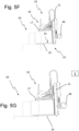
- the gripper head 10 is moved from the position to Fig. 5E into the position after Fig. 5F moved, whereby the lower gripping unit 19 dips further into the gap L until the respective packaging blanks, which are to be clamped by the gripper head 10, are completely carried by the lower gripping unit 19 of the gripper head 10.
- the upper gripping unit 17 is moved via the pneumatic cylinder 25 (cf. Fig. 2A ) in the direction of the lower gripping unit 19 until the upper gripping unit 17 comes into contact with a respective upper packaging blank and the respective packaging blanks are held with a predetermined clamping force between the upper gripping unit 17 and the lower gripping unit 19.
- Fig. 5G The packaging blanks are clamped by the upper gripping unit 17 and the lower gripping unit 19. As shown in FIG. 5f, it may be sufficient if the lower gripping unit 19 only dips into the gap L to a position at which the upper gripping unit 17, during clamping engagement, only comes into contact with a partial area of the upper packaging blank. It is therefore not necessary for the lower gripping unit 19 to dip into the gap L to a position at which the respective packaging blanks to be clamped are already in the vicinity of the frame 12.
- FIG. 6 The schematic representation of the Fig. 6 shows further aspects as they can be provided in various embodiments of the method 100 according to the invention.
- Fig. 6 Packaging blanks that are to be clamped and which differ in terms of their dimensions from the packaging blanks according to Figures 5A to 5G
- the lower gripping unit 19 is still inserted into the gap L for clamping acceptance, but compared to the embodiment according to Figures 5A to 5G with a greater immersion depth. This enables secure clamping even with larger packaging blanks when the upper gripping unit 17 and the lower gripping unit 19 subsequently perform a feed movement.
- FIGS. 7A to 7C show steps as they can be carried out individually or according to the Figures 7A to 7C shown combination can be provided in further embodiments of the method 100 according to the invention.
- the method 100 is carried out by means of a gripper head 10, as previously described in the embodiment according to Figures 1A and 1B was presented and described.
- Fig. 7A The gripper head 10 has already clamped several packaging blanks from the stack 50.
- the upper gripper unit 17 and the lower gripper unit 19 are in Fig. 7A with the clamped packaging blanks in the system.
- a respective outer edge of the packaging blanks still to be received was lifted by means of the separating unit 18 and a gap L was formed, as is the case with the embodiment according to Figures 5A to 5G has already been mentioned and described.
- FIG. 7B A further step will be taken by a summary of the Fig. 7B with Fig. 7C
- the first fork tines 27 and the inner fork tines 29 are lowered together until the outer fork tines 29 ⁇ come into contact with the already clamped packaging blanks.
- Portions of the packaging blanks that protrude beyond the inner fork tines 29 in the direction of the image and opposite to the direction of the image are Fig. 7C supported by the outer forks 29 ⁇ .
- a manipulator 1 transports the gripper head 10 together with the clamped packaging blanks to a delivery location in a subsequent step, the risk of packaging blanks unintentionally detaching from the gripper head 10 is very low. Furthermore, the described procedure prevents clamped packaging blanks from sagging, which in turn can have a detrimental effect on their handling. By preventing such sagging, the risk of clamped packaging blanks being damaged, and in particular, bent, during transport to the delivery location can be reduced or even eliminated.
- the described procedure ensures a high level of process reliability during the subsequent positioning of the clamped packaging blanks at the destination, where a storage area 62 may be located.
- the described procedure has also proven effective when the clamped packaging blanks are to be inserted into a space-limited cutout, which, for example, is formed by an opening 6 (see Fig. 11A ).
- the outer fork tines 29' may be raised until the outer fork tines 29' come into contact with the packaging blanks that have already been clamped.
- the Fig. 8 shows a schematic perspective view of an embodiment of a packaging system 60 according to the invention.
- the packaging system 60 comprises a Fig. 8 Manipulator 1, not shown, which is designed as an articulated arm robot 1' and carries a gripper head 10.
- the gripper head 10 has an upper gripping unit 17 and a lower gripping unit 19, which can each perform a feed movement to clamp and grasp several packaging blanks.
- the packaging system comprises a storage area 62, which forms a support surface 64.
- the manipulator 1 can place the respective clamped packaging blanks onto the support surface 64 via the gripper head 10.
- the lower gripping unit 19 of the gripper head 10 comprises two fork tines 28 oriented parallel to one another.
- the respective plurality of packaging blanks rest on the fork tines 28.
- the contact surface 64 of the support 62 forms a plurality of slots 7, the respective width of which corresponds to the fork tines 28 in such a way that the fork tines 28 can pass through the contact surface 64 via the slots 7.
- a plurality of packaging blanks can be placed quickly and easily onto the contact surface 64 via the gripper head 10.
- a respective slot 7 is formed in the depositor 62 between two immediately adjacent conveyor belts 69.
- the depositor 62 has a plurality of strips that are moved in the direction of the gripper head 10 in order to receive the respective plurality of clamped packaging blanks from the gripper head 10.
- the respective received packaging blanks are moved to a centering device 70, which aligns the multiple packaging blanks flush. From there, the packaging blanks are transported further, and articles, which are beverage containers, are packaged with the packaging blanks.
- the centering device and the storage unit 62 are thus designed as components of a Fig. 8 not fully shown packaging device, which packaging device in turn forms a component of the packaging system 60.
- a gripper head 10 is shown in Fig. 8 It is also conceivable that the gripper head 10 of the packaging system 60 comprises several inner fork tines 29 and several outer fork tines 29', as in the embodiment according to Figures 1A and 1B has already been shown and which plurality of inner forks 29 and/or which plurality of outer forks 29 can be moved via the slots 7 through the support surface 64 of the shelf 62.
- Fig. 9 shows a schematic view of another embodiment of a packaging system 60 according to the invention.
- a gripper head is shown, which can clamp several packaging blanks together.
- a stack 50 of packaging blanks and several further stacks 51 to 57 of packaging blanks are shown.
- the Fig. 9 clarifies in particular a sequence in which the gripper head 10 receives a plurality of packaging blanks and places them on the storage unit 62.
- the gripper head 10 begins with the plurality of packaging blanks from the stack 50 and moves these plurality of packaging blanks to the storage unit 62.
- the gripper head 10 then continues to remove the respective further plurality of packaging blanks from the stacks 51 to 57 in a continuous sequence.
- the gripper head 10 comprises a separating unit 18 with a stop 32, as shown in the embodiment according to Figures 3A to 3C has already been shown. Via the stop 32, the gripper head 10 presses the respective multiple packaging blanks that still need to be clamped towards the stop wall 5, whereby the respective packaging blanks are aligned flush with one another.
- Further packaging blanks from further stacks 51 to 57 can be held down by a hold-down device 63 (cf. Fig. 16 ) are pressed downwards, with such a hold-down device being placed on a respective uppermost packaging blank of the respective further stack 51 to 57.
- a hold-down device 63 cf. Fig. 16
- the gripper head 10 first receives the respective plurality of packaging blanks from the stack 50 and the further stacks 51 to 53 in a cyclic manner and sets them down on the storage device 62.
- the hold-down device 63 can press the respective plurality of packaging blanks of the further stacks 54 to 57 downwards.
- the hold-down device 63 can be displaced toward another row of stacks toward the stop wall 5 and press these packaging blanks downward. The movement or position of the hold-down device 63 can thus be coordinated with the receipt of packaging blanks via the gripper head 10.
- the Fig. 10A shows a schematic perspective view of another embodiment of a gripper head 10 according to the invention.
- the gripper head 10 comprises a frame 12 formed by several welded sheet metal parts.
- the lower gripping unit 19 can be raised and lowered via a pneumatic cylinder 25.
- the gripper head 10 also comprises a separating unit 18, via which the outer edges of the respective packaging blanks to be clamped can be lifted.
- the separating unit 18 is movable by actuator along the inner fork tines 29.
- the upper gripping unit 17 comprises a sheet metal part 8. By actuating the piston-cylinder units 9, the sheet metal part 8 can be pivoted, placed on a packaging blank arranged at the top and already picked up by the inner fork tines 29, and clamped to the gripper head 10.
- the Fig. 10B shows the gripper head 10 of the embodiment according to Fig. 10A from below.
- the gripper head 10 comprises a linear guide 4, along which the inner fork tines 29 of the gripper head 10 can move.
- a direction of movement runs parallel to the respective longitudinal extent of the inner fork tines 29 and parallel to the longitudinal extent of the outer fork tines 29'.
- the gripper head 10 Compared to the embodiments already described, the gripper head 10 according to Figures 10A and 10B This makes it possible to pick up several packaging blanks at a time without the gripper head 10 having to be moved via a working arm 48 of a manipulator 1 in order to insert the inner fork tines 29 into a gap L.
- FIGS 11A and 11B illustrate further advantages of the embodiment of a gripper head 10 according to Figures 10A and 10B .
- the respective packaging blanks have already been clamped by the gripper head 10.
- Figures 11A and 11B illustrate a transfer of the packaging blanks to a storage unit 62.
- the plurality of packaging blanks can be brought into contact with the separating unit 18 after being picked up via the inner fork tines 29 by moving the inner fork tines 29 along the linear guide 4 in the direction of the frame 12.
- the sheet metal part 8 is placed on an upper packaging blank with force only in a small area that is close to the separating unit 18.
- the shelf 62 forms Figures 11A and 11B an opening 6 into which the packaging blanks are to be inserted via the gripper head 10.
- the opening 6 is dimensioned in such a way that the gripper head 10 cannot be moved completely into the opening 6 in order to transfer the packaging blanks to the storage unit 62.
- the sheet metal part 8 is first pivoted upwards via the pneumatic cylinder 9, whereby it reaches a waiting position, which in Figures 11A and 11B is shown. Such a movement of the sheet metal part 8 enables the gripper head 10 to be moved very close to the opening 6 in order to subsequently transfer the packaging blanks to the storage device 62.
- the packaging blanks can be inserted into the opening 6 by moving the gripper head 10 over the working arm 48 of the manipulator 1 until all packaging blanks to be transferred to the storage unit 62 are located in the opening.
- the inner fork tines 29 extended or moved along the linear guide 4, whereby the packaging blanks enter the opening 6.
- the packaging blanks are set down, whereupon the gripper head 10 is moved towards a Figures 11A and 11B is not moved with the stack 50 shown.
- the Fig. 12 shows an embodiment of a storage unit 62, as it can be provided in various embodiments of a packaging system 60 according to the invention as well as in various embodiments of the method 100 according to the invention.
- the storage unit 62 is designed as a component of an adapter 3 and stands on a support frame 14 or is carried by a support frame 14.
- An opening 6 in the adapter 3 is designed such that a complete gripper head 10 cannot be moved into the opening 6.
- an embodiment of a gripper head 10 as previously described in the Figures 10A and 10B and 11A and 11B.
- the adapter 3 has several clamping means 26', which can be placed on a respective upper packaging blank in order to securely hold the respective multiple packaging blanks on the storage device 62.
- the adapter 3 has a coupling 23, via which the adapter 3 can be coupled to an automated guided vehicle or an AGV, so that the adapter 3 is supplied with electrical energy and, if necessary, compressed air from the automated guided vehicle or AGV via the coupling 23.
- Reference number 43 refers to a mat track, by means of which the adapter 3 can transport already picked up packaging blanks and, if necessary, transfer them to another device. The direction of movement is in Fig. 12 indicated by arrows.
- the Fig. 13 shows a schematic view of an embodiment of a packaging system 60 and a further embodiment of a gripper head 10 according to the invention.
- the packaging system 60 shown comprises a supply device 80, via which a stack 50 of packaging blanks is provided.
- a stop wall 5 of the supply device 80 is located in the area of the stack 50.
- the respective multiple packaging blanks are moved over the stop 32 of the separating unit 18 (cf. Figures 3A to 3C ) against the stop wall 5 of the supply device 80, whereby the front and rear edges of the respective packaging blanks to be picked up are aligned flush with each other.
- the gripper head 10 comprises two centering elements 39, of which Fig. 13 only a centering element 39 is shown.
- the centering element 39 can be moved in a linear direction and thereby aligns the lateral outer edges of the respective packaging blanks that are still to be completely picked up flush with each other.
- Fig. 13 the packaging blanks of the stack 50 to be picked up are only partially arranged on the lower gripping unit 19.
- the gripper head 10 transfers the respective packaging blanks to the storage unit 62, which in Fig. 13 is shown only schematically.
- the tray 62 can be part of a packaging device which packages beverage containers using the received packaging blanks.
- Fig. 14 shows further details as they can be provided in various embodiments of the packaging system 60 according to the invention as well as in various embodiments of the method 100 according to the invention.
- Fig. 14 illustrates a possibility with which the Fig. 14 several packaging blanks already picked up by the gripper head 10 can be aligned flush with each other.
- the gripper head 10 is in Fig. 14 connected to a manipulator 1 (not shown). After picking up the plurality of packaging blanks, the upper gripping unit 17 and the lower gripping unit 19 are moved apart, so that the upper gripping unit 17 and the lower gripping unit 19 are thereby moved into the position according to Fig. 14 The gripper head 10 is then rotated via the manipulator 1 in such a way that the picked-up packaging blanks are pushed against the Separating unit 18, whereby the outer edges of these multiple packaging blanks are aligned flush with each other.
- a gripper head 10 according to the embodiment of Fig. 14 may also include centering elements 39, as previously described for Fig. 13 shown and described, and via which centering elements 39, lateral outer edges of the respective multiple picked-up packaging blanks can be additionally aligned flush with one another.
- the gripper head 10 may also be rotated about an axis that runs parallel to the first fork tines 27 or to the outer fork tines 29' and the inner fork tines 29, whereby the picked-up packaging blanks slide against a centering element 30 due to gravity, whereby the lateral outer edges of the multiple picked-up packaging blanks are aligned flush with one another.
- the Fig. 15 shows a schematic view of another embodiment of a gripper head 10 according to the invention.
- the embodiment according to Fig. 15 further comprises a separating unit 18 according to the previous description of the Figures 3A to 3C .
- the gripper head 10 also comprises a frame 12 and a lower gripping unit 19 and an upper gripping unit 17, of which Fig. 15 only the lower gripping unit 19 was shown.
- a component of the gripper head 10 is also a suction instrument 49.
- a suction instrument 49 as it is Fig. 15 is not limited to the embodiment according to Fig. 15 limited, but can be provided in a general context as well as in all previously described embodiments of a gripper head 10.
- a gripper head 10 can also comprise several such suction instruments.
- a gripper head 10 can also have other gripping instruments, such as at least one needle gripper, at least one adhesion gripper or at least one gripping instrument operating via electrostatic adhesion or a gripping instrument supported by electrostatic adhesion, which can receive a packaging blank.
- other gripping instruments such as at least one needle gripper, at least one adhesion gripper or at least one gripping instrument operating via electrostatic adhesion or a gripping instrument supported by electrostatic adhesion, which can receive a packaging blank.
- At least one individual packaging blank of a stack 50 remains if several packaging blanks have been removed from stack 50 in several steps by means of a gripper head 10.
- the last packaging blank can be grasped by a suction instrument 49 or by the previously mentioned gripping instruments and then brought to a destination via the gripper head 10.
- packaging materials which may be, for example, cover boards, strapping bands, intermediate layers or even pallets, are grasped by means of the suction instrument 49 or by means of the gripping instruments described above and brought to a predetermined destination.
- FIG. 15 As indicated by the arrows, embodiments have proven successful in which the suction instrument 49 can be moved into different positions relative to the frame 12 by means of an actuator. This allows even packaging blanks, materials or other objects that are difficult to access to be pneumatically grasped.
- suction instrument 49 is designed as a component of the gripper head 10 in the present case, in various embodiments of a packaging system 60 according to the invention, it can be additional or alternative to this that such a suction instrument 49 is designed as a component of an additional device, with which device a last packaging blank of a stack 50 is pneumatically received, packaging materials are pneumatically grasped or even a pallet or cover boards are pneumatically received and brought to a desired destination.
- the Fig. 16 shows a schematic view of another embodiment of a packaging system 60 according to the invention.
- the packaging system 60 comprises a manipulator 1, which is an articulated-arm robot 1'.
- the manipulator 1 carries a gripper head 10, which can be designed in particular according to an embodiment of the previous description.
- two stacks 50 of packaging blanks are provided via the supply device 80.
- More than two stacks 50 may also be provided, which are provided via the supply device 80.
- the two stacks 50 are located on a pallet 71.
- the manipulator 1 can clamp several packaging blanks from the stack 50 via the gripper head 10 and place them on a Fig. 16 Do not place it on the shelf 62 shown.
- the supply device 80 comprises a turntable 72 on which the stacks 50 of packaging blanks are arranged.
- the turntable 72 can be rotated about a vertically oriented axis, whereby one of the two stacks 50 enters the access area of the manipulator 1.
- a stack 50 may comprise a plurality of packaging blanks arranged in different rotational orientations on the stack 50. If, for example, packaging blanks of the stack 50 have a longitudinal side and a transverse side with different lengths and the manipulator 1 is designed to receive packaging blanks with such a rotational orientation via the gripper head 10, in which rotational orientation the longitudinal side points in the direction of the manipulator 1 or in the direction of the gripper head 10, the respective packaging blanks of the stack 50 to be received can be brought into the appropriate rotational orientation intended for receipt by a corresponding rotation of the turntable 72, in which the longitudinal side points in the direction of the manipulator 1 or in the direction of the gripper head 10.
- the supply device 80 comprises a stop wall 5.
- the stop wall 5 is movable in the horizontal direction by an actuator, whereby the packaging blanks of the respective stack can be aligned flush with one another.
- the supply device 80 comprises a hold-down device 63, which can be placed on one or more stacks 50 in order to fix the respective packaging blanks of the respective stack 50 on the turntable 72.
- the hold-down device 63 can fix packaging blanks of a further stack 50 in order to prevent packaging blanks of the further stack 50 from slipping.
- the central controller S is connected to a sensor system 41 and can detect the respective actual height of a respective stack 50 via the sensor system 41. Taking into account the respective detected actual height, the manipulator 50 is actuated via the central controller S in order to clamp and accept packaging blanks from the respective stack 50.
- the sensor system 41 can, for example, be an optical sensor system, such as a camera or the like.
- the central controller S can use the sensor system 41 to detect a respective position of the respective multiple packaging blanks to be received and control the manipulator 1 taking into account the detected position of the respective multiple packaging blanks to be received.
- this can ensure that the respective plurality of packaging blanks are located at an expected target position after a clamping acceptance via the gripper head 10 and are therefore securely held on the gripper head 10.
- the Fig. 17 shows the embodiment of a packaging device 60 according to Fig. 16 in top view.
- the manipulator 1 with the gripper head 10, the hold-down device 63, and the stop wall 5 can be seen again.
- the turntable 71 forms a support surface 64 on which the stacks 5 rest.
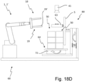
- FIGS. 18A to 18D show a schematic view of another embodiment of a packaging device 60 according to the invention.
- the Figures 18A to 18D individual steps, they can be provided in various embodiments of the method 100 according to the invention.
- a packaging device 60 differs according to the Figures 18A to 18D in particular in that the stop wall 5 as well as the hold-down device 63 and the turntable 72 can be rotated about a common horizontal axis
- the stop wall 5, the hold-down device 63 and the turntable 72 are connected to a pivoting device 74.
- FIG. 18A Several stacks 50 of packaging blanks are already positioned on the turntable 72 of the supply device 80.
- the hold-down device 63 is placed on each of the two stacks 50 positioned next to each other and clamps the stacks 50 onto the turntable 72. From there, the hold-down device 63, the turntable 72 and the stop wall 5 are rotated by 180° about a horizontal axis by means of the pivoting device 74, so that the stacks 5 of packaging blanks, as shown in Fig. 18B shown, rest on the hold-down device 63.
- the turntable 72 was Fig. 18B already raised and is spaced from the pallet 71.
- the hold-down device 63 may be lowered together with the stacks 50 relative to the turntable 72 and thereby moved into the position according to Fig. 18B reached.
- the gripper head 10 is designed to receive a pallet 71, as is also shown in Fig. 18B shown.
- the gripper head 10 has corresponding means that can dip into free spaces of the pallet 71 in order to pick up the pallet 71.
- the gripper head 10 can also dip with one or more of its forks into one or more free spaces of the pallet 71 and pick up the pallet 71.
- the pallet 71 can be a Euro pallet.
- Such a pickup of a pallet 71 is not limited to the embodiment according to Figures 18A to 18D limited, but can be provided in the general context and in particular in the previously described embodiments of a packaging system 60 and a gripper head 1.
- Fig. 18B The manipulator 1 removes the pallet 71 from the stacks 50 of packaging blanks via the gripper head 10.
- pallet 71 has already left the stack of 50 packaging blanks.
- the turntable 72 can be placed on the stack 50 of packaging blanks, whereupon the turntable 72, the hold-down device 63 and the stop wall 5 can be rotated again by 180° about the horizontal axis via the pivoting device 74 or rotated back by 180°.
- the stacks of 50 packaging blanks are then positioned accordingly Fig. 18D on the turntable 72 without a pallet 71 being located between the turntable 72 and the stacks 50 of packaging blanks.
- the turntable 72 has a support surface 62 for the stacks 50 of packaging blanks, which forms a plurality of slots 7, as already shown for the storage 64 for the embodiment according to Fig. 8
- the fork tines 29 and 29' of the lower gripping unit 19 can thereby be inserted into the slots 7 and thus easily remove all packaging blanks of a stack 50 from the turntable 72.
- the Figures 19A and 19B show an embodiment of a supply device 80, as can be provided in various embodiments of a packaging system 60 according to the invention.
- the supply device 80 comprises a centering device 85 with several centering bars 87.
- the centering bars 87 can execute a feed movement. This centers packaging blanks from stacks 50 that are located in a common plane or arranged at the same height. Subsequently, the centering bars 87 are moved downward and are then located vertically at the height of another plane of several additional stacks 50 of packaging blanks.
- the packaging blanks of these stacks 50 located in the further plane are also aligned flush with one another.
- the centering device 85 thus successively aligns the packaging blanks of stacks 50 located in a respective common plane flush with one another. This allows a gripper head 10 to securely pick up and clamp multiple packaging blanks of a respective stack 50, since the respective packaging blanks are located in a respective expected target position.
- a gripper head 10 dips over a projection 34 formed as a component of a separating unit 18 of the gripper head 10 (cf. Figures 3A to 3C ) into a stack 50 of packaging blanks and then lifts several packaging blanks arranged on the projection 34 over the separating unit 18.
- a linear lifting axis HA, along which the projection 34 is moved for this purpose, is inclined relative to a contact surface 24 for packaging blanks at an angle of between 5° and 30°.
- the angle can be 18° or substantially 18°.
- step 120 a lower gripping unit 19 of the gripper head 10 is inserted into the stack 50 of packaging blanks in the region of the raised outer edges, so that the respective packaging blanks still to be clamped are completely carried by the lower gripping unit 19.
- step 130 the packaging blanks completely carried by the lower gripping unit 19 are clamped by the lower gripping unit 19 and an upper gripping unit 17 of the gripper head 10 and subsequently, in step 140, transported via the gripper head 10 toward a predetermined destination.
- a manipulator 1 which may in particular be an articulated-arm robot 1', may be provided for moving the gripper head 140.
- a packaging device, to which the multiple packaging blanks are transferred from the gripper head 10, may be located at the destination.
Landscapes
- Engineering & Computer Science (AREA)
- Mechanical Engineering (AREA)
- Robotics (AREA)
- Sheets, Magazines, And Separation Thereof (AREA)
- Manipulator (AREA)
Applications Claiming Priority (1)
| Application Number | Priority Date | Filing Date | Title |
|---|---|---|---|
| DE102023130970.6A DE102023130970A1 (de) | 2023-11-08 | 2023-11-08 | Greiferkopf und Verfahren zur Handhabung von Verpackungszuschnitten |
Publications (1)
| Publication Number | Publication Date |
|---|---|
| EP4553014A1 true EP4553014A1 (fr) | 2025-05-14 |
Family
ID=93154487
Family Applications (1)
| Application Number | Title | Priority Date | Filing Date |
|---|---|---|---|
| EP24207104.1A Pending EP4553014A1 (fr) | 2023-11-08 | 2024-10-17 | Tête de préhension et procédé de manipulation de découpes d'emballage |
Country Status (4)
| Country | Link |
|---|---|
| US (1) | US20250145390A1 (fr) |
| EP (1) | EP4553014A1 (fr) |
| CN (1) | CN223619016U (fr) |
| DE (1) | DE102023130970A1 (fr) |
Citations (5)
| Publication number | Priority date | Publication date | Assignee | Title |
|---|---|---|---|---|
| EP1129843A1 (fr) * | 2000-03-03 | 2001-09-05 | Serco B.V. | Méthode et appareil de séparation de flans pour boítes en carton |
| EP2046668B1 (fr) * | 2006-08-03 | 2012-02-01 | TGW Mechanics GmbH | Dispositif de transport pour dépalétiser des marchandises empilées sur un support de marchandises |
| US8777551B1 (en) * | 2011-07-14 | 2014-07-15 | Automatan, Inc. | Robotic lifting apparatus |
| DE102016218319A1 (de) * | 2016-09-23 | 2018-03-29 | Fraunhofer-Gesellschaft zur Förderung der angewandten Forschung e.V. | Aufnahmevorrichtung zum Greifen eines Objektes |
| CN114455354A (zh) * | 2022-04-14 | 2022-05-10 | 广东隆崎机器人有限公司 | 转移机构、转移设备 |
Family Cites Families (6)
| Publication number | Priority date | Publication date | Assignee | Title |
|---|---|---|---|---|
| DE4222609A1 (de) * | 1992-07-10 | 1994-01-20 | Focke & Co | Verfahren und Vorrichtung zum Handhaben von Zuschnitt-Stapeln |
| IT1274871B (it) * | 1994-07-29 | 1997-07-25 | Wrapmatic Spa | Dispositivo di selezione di grandi risme sfuse. |
| DE102012018438B4 (de) * | 2012-09-19 | 2018-12-13 | Eisenmann Alpha-Tec Gmbh | Handhabungseinrichtung mit einem Manipulator für Materialstücke |
| DE102021117061A1 (de) * | 2021-07-02 | 2023-01-05 | Khs Gmbh | Zuschnittzuführanordnung und Verpackungsmaschine zur Bildung von Verkaufsgebinden |
| CN117425605A (zh) * | 2021-08-06 | 2024-01-19 | 克朗斯股份公司 | 用于平面包装坯件的运输装置和具有用于平面包装坯件的运输装置的包装系统 |
| DE102022001542A1 (de) * | 2022-05-03 | 2023-11-09 | Giesecke+Devrient Currency Technology Gmbh | Ablegen eines Blattgutstapels |
-
2023
- 2023-11-08 DE DE102023130970.6A patent/DE102023130970A1/de active Pending
-
2024
- 2024-10-17 EP EP24207104.1A patent/EP4553014A1/fr active Pending
- 2024-10-22 CN CN202422550383.1U patent/CN223619016U/zh active Active
- 2024-11-07 US US18/939,796 patent/US20250145390A1/en active Pending
Patent Citations (5)
| Publication number | Priority date | Publication date | Assignee | Title |
|---|---|---|---|---|
| EP1129843A1 (fr) * | 2000-03-03 | 2001-09-05 | Serco B.V. | Méthode et appareil de séparation de flans pour boítes en carton |
| EP2046668B1 (fr) * | 2006-08-03 | 2012-02-01 | TGW Mechanics GmbH | Dispositif de transport pour dépalétiser des marchandises empilées sur un support de marchandises |
| US8777551B1 (en) * | 2011-07-14 | 2014-07-15 | Automatan, Inc. | Robotic lifting apparatus |
| DE102016218319A1 (de) * | 2016-09-23 | 2018-03-29 | Fraunhofer-Gesellschaft zur Förderung der angewandten Forschung e.V. | Aufnahmevorrichtung zum Greifen eines Objektes |
| CN114455354A (zh) * | 2022-04-14 | 2022-05-10 | 广东隆崎机器人有限公司 | 转移机构、转移设备 |
Also Published As
| Publication number | Publication date |
|---|---|
| US20250145390A1 (en) | 2025-05-08 |
| CN223619016U (zh) | 2025-12-02 |
| DE102023130970A1 (de) | 2025-05-08 |
Similar Documents
| Publication | Publication Date | Title |
|---|---|---|
| EP3730433A2 (fr) | Dispositif de dépalettisation doté d'un dispositif de dépalettisation de récipients empilables pour marchandise de détail et procédé de dépalettisation de récipients empilables pour marchandise de détail | |
| EP4067271B1 (fr) | Préhenseur et procédé de manipulation des marchandises en détail | |
| EP3666696B1 (fr) | Dispositif et procede pour manipuler des couches de marchandises unitaires superposees | |
| EP3652092B1 (fr) | Procédé et dispositif de manipulation de marchandises de détail, d'articles et/ou d'emballages | |
| EP2736810A2 (fr) | Dispositif et procédé de déballage et d'amenée d'emballages de conditionnement pliés à plat et debout | |
| DE102017121557B4 (de) | Verfahren und Vorrichtung zur Förderung und Positionierung von Werkstücken | |
| WO2023011899A2 (fr) | Dispositif de transport pour pièces découpées d'emballage planes et système d'emballage doté d'un dispositif d'emballage pour pièces découpées d'emballage planes | |
| DE102009011301B4 (de) | Verfahren und Greifer zur Handhabung eines Gebindes mittels eines Manipulators | |
| EP4186829B1 (fr) | Dispositif de préhension et procédé de manipulation de marchandises de détail | |
| EP3626634B1 (fr) | Dispositif de manipulation et / ou d'emballage et procédé d'emballage des articles | |
| DE102010034992B4 (de) | Einrichtung zur Handhabung quaderförmiger Gegenstände | |
| EP3623323B1 (fr) | Procédé et dispositif de manipulation des marchandises, des articles et / ou des emballages | |
| EP4553014A1 (fr) | Tête de préhension et procédé de manipulation de découpes d'emballage | |
| DE4417806C2 (de) | Verfahren und Vorrichtung zur automatischen Bereitstellung eines Bogenstapels für eine Druckmaschine | |
| EP0391837A2 (fr) | Dispositif destiné à palletiser des récipients | |
| DE102020108037B4 (de) | Positionierungseinrichtung und Verfahren zur Positionierung von Werkstücken | |
| EP4137281A1 (fr) | Palettisation et/ou dépalletisation | |
| EP3529183B1 (fr) | Procédé et dispositif pour la manutention de découpes planes d'une pile comprenant une pluralité de découpes planes | |
| DE102015200725A1 (de) | Vorrichtung und Verfahren zum Trennen einzelner Zwischenlagen von einem Zwischenlagenstapel | |
| AT526215B1 (de) | Transfervorrichtung und Verfahren zum Handhaben von Packeinheiten | |
| EP2773580B1 (fr) | Dispositif de transport et de manutention de produits | |
| DE102022132193A1 (de) | Greiferkopf und Verfahren zum Erfassen und Manipulieren von Stückgütern | |
| DE4317283C1 (de) | Handhabungsgerät, insbesondere Greifer, zum Anschluß an den Arm eines Industrieroboters | |
| DE102022132191A1 (de) | Greiferkopf und Verfahren zum Erfassen und Manipulieren von Stückgütern | |
| DE102023131679A1 (de) | Greiferkopf und Verfahren zum Erfassen und Manipulieren von Stückgütern |
Legal Events
| Date | Code | Title | Description |
|---|---|---|---|
| PUAI | Public reference made under article 153(3) epc to a published international application that has entered the european phase |
Free format text: ORIGINAL CODE: 0009012 |
|
| STAA | Information on the status of an ep patent application or granted ep patent |
Free format text: STATUS: THE APPLICATION HAS BEEN PUBLISHED |
|
| AK | Designated contracting states |
Kind code of ref document: A1 Designated state(s): AL AT BE BG CH CY CZ DE DK EE ES FI FR GB GR HR HU IE IS IT LI LT LU LV MC ME MK MT NL NO PL PT RO RS SE SI SK SM TR |
|
| STAA | Information on the status of an ep patent application or granted ep patent |
Free format text: STATUS: REQUEST FOR EXAMINATION WAS MADE |
|
| 17P | Request for examination filed |
Effective date: 20251111 |