EP4080109A1 - Luminaire multifonction destiné à l'éclairage d'un poste de travail - Google Patents
Luminaire multifonction destiné à l'éclairage d'un poste de travail Download PDFInfo
- Publication number
- EP4080109A1 EP4080109A1 EP22169165.2A EP22169165A EP4080109A1 EP 4080109 A1 EP4080109 A1 EP 4080109A1 EP 22169165 A EP22169165 A EP 22169165A EP 4080109 A1 EP4080109 A1 EP 4080109A1
- Authority
- EP
- European Patent Office
- Prior art keywords
- light
- light emission
- lamp
- lighting fixture
- luminaire according
- Prior art date
- Legal status (The legal status is an assumption and is not a legal conclusion. Google has not performed a legal analysis and makes no representation as to the accuracy of the status listed.)
- Granted
Links
Images





Classifications
-
- F—MECHANICAL ENGINEERING; LIGHTING; HEATING; WEAPONS; BLASTING
- F21—LIGHTING
- F21S—NON-PORTABLE LIGHTING DEVICES; SYSTEMS THEREOF; VEHICLE LIGHTING DEVICES SPECIALLY ADAPTED FOR VEHICLE EXTERIORS
- F21S6/00—Lighting devices intended to be free-standing
-
- F—MECHANICAL ENGINEERING; LIGHTING; HEATING; WEAPONS; BLASTING
- F21—LIGHTING
- F21S—NON-PORTABLE LIGHTING DEVICES; SYSTEMS THEREOF; VEHICLE LIGHTING DEVICES SPECIALLY ADAPTED FOR VEHICLE EXTERIORS
- F21S10/00—Lighting devices or systems producing a varying lighting effect
- F21S10/02—Lighting devices or systems producing a varying lighting effect changing colors
-
- F—MECHANICAL ENGINEERING; LIGHTING; HEATING; WEAPONS; BLASTING
- F21—LIGHTING
- F21S—NON-PORTABLE LIGHTING DEVICES; SYSTEMS THEREOF; VEHICLE LIGHTING DEVICES SPECIALLY ADAPTED FOR VEHICLE EXTERIORS
- F21S6/00—Lighting devices intended to be free-standing
- F21S6/002—Table lamps, e.g. for ambient lighting
-
- F—MECHANICAL ENGINEERING; LIGHTING; HEATING; WEAPONS; BLASTING
- F21—LIGHTING
- F21S—NON-PORTABLE LIGHTING DEVICES; SYSTEMS THEREOF; VEHICLE LIGHTING DEVICES SPECIALLY ADAPTED FOR VEHICLE EXTERIORS
- F21S9/00—Lighting devices with a built-in power supply; Systems employing lighting devices with a built-in power supply
- F21S9/02—Lighting devices with a built-in power supply; Systems employing lighting devices with a built-in power supply the power supply being a battery or accumulator
-
- F—MECHANICAL ENGINEERING; LIGHTING; HEATING; WEAPONS; BLASTING
- F21—LIGHTING
- F21V—FUNCTIONAL FEATURES OR DETAILS OF LIGHTING DEVICES OR SYSTEMS THEREOF; STRUCTURAL COMBINATIONS OF LIGHTING DEVICES WITH OTHER ARTICLES, NOT OTHERWISE PROVIDED FOR
- F21V21/00—Supporting, suspending, or attaching arrangements for lighting devices; Hand grips
- F21V21/10—Pendants, arms, or standards; Fixing lighting devices to pendants, arms, or standards
-
- F—MECHANICAL ENGINEERING; LIGHTING; HEATING; WEAPONS; BLASTING
- F21—LIGHTING
- F21V—FUNCTIONAL FEATURES OR DETAILS OF LIGHTING DEVICES OR SYSTEMS THEREOF; STRUCTURAL COMBINATIONS OF LIGHTING DEVICES WITH OTHER ARTICLES, NOT OTHERWISE PROVIDED FOR
- F21V21/00—Supporting, suspending, or attaching arrangements for lighting devices; Hand grips
- F21V21/14—Adjustable mountings
- F21V21/30—Pivoted housings or frames
-
- F—MECHANICAL ENGINEERING; LIGHTING; HEATING; WEAPONS; BLASTING
- F21—LIGHTING
- F21V—FUNCTIONAL FEATURES OR DETAILS OF LIGHTING DEVICES OR SYSTEMS THEREOF; STRUCTURAL COMBINATIONS OF LIGHTING DEVICES WITH OTHER ARTICLES, NOT OTHERWISE PROVIDED FOR
- F21V23/00—Arrangement of electric circuit elements in or on lighting devices
- F21V23/04—Arrangement of electric circuit elements in or on lighting devices the elements being switches
- F21V23/0442—Arrangement of electric circuit elements in or on lighting devices the elements being switches activated by means of a sensor, e.g. motion or photodetectors
- F21V23/045—Arrangement of electric circuit elements in or on lighting devices the elements being switches activated by means of a sensor, e.g. motion or photodetectors the sensor receiving a signal from a remote controller
-
- F—MECHANICAL ENGINEERING; LIGHTING; HEATING; WEAPONS; BLASTING
- F21—LIGHTING
- F21V—FUNCTIONAL FEATURES OR DETAILS OF LIGHTING DEVICES OR SYSTEMS THEREOF; STRUCTURAL COMBINATIONS OF LIGHTING DEVICES WITH OTHER ARTICLES, NOT OTHERWISE PROVIDED FOR
- F21V33/00—Structural combinations of lighting devices with other articles, not otherwise provided for
- F21V33/0004—Personal or domestic articles
- F21V33/0052—Audio or video equipment, e.g. televisions, telephones, cameras or computers; Remote control devices therefor
-
- F—MECHANICAL ENGINEERING; LIGHTING; HEATING; WEAPONS; BLASTING
- F21—LIGHTING
- F21W—INDEXING SCHEME ASSOCIATED WITH SUBCLASSES F21K, F21L, F21S and F21V, RELATING TO USES OR APPLICATIONS OF LIGHTING DEVICES OR SYSTEMS
- F21W2131/00—Use or application of lighting devices or systems not provided for in codes F21W2102/00-F21W2121/00
- F21W2131/40—Lighting for industrial, commercial, recreational or military use
- F21W2131/402—Lighting for industrial, commercial, recreational or military use for working places
Definitions
- the present invention relates to a lamp that is provided for illuminating a workplace, in particular for illuminating a home office workplace.
- the requirements for professional lighting of workplaces are defined by a large number of regulations and standards. This describes the brightness with which workplaces are to be illuminated in order to enable efficient work, for example reading or editing documents. Furthermore, the light should be emitted in a specific way in order to avoid disruptive reflections, for example on screen surfaces. All of these measures contribute to creating a working environment in which, at least in terms of lighting conditions, there are optimal conditions for efficient work.
- the present invention is based on the task of offering a solution for the above-described situation of home office work, with the help of which the best possible lighting situation is created in a simple manner, which facilitates work and promotes the well-being of the person working.
- the core idea of the present invention is to provide a lamp that can be used in a simple and flexible manner in order to create optimized lighting conditions in the space used for home office work. It is assumed here that the home office work takes place predominantly with the help of a laptop or a comparable portable work device, in which case the lamp according to the invention is then initially designed to illuminate the area in the vicinity of the laptop and a person using the work device with as little glare as possible .
- the lamp has a plate-like lighting element as a central element, which can be positioned in a substantially vertically aligned manner with the aid of suitable fastening means and can in particular be arranged behind the display of a laptop.
- first light-emitting means are provided, which emit light over a frame-like surface area framing the screen of the laptop over a large area.
- the lamp according to the invention can therefore be flexibly positioned on the back of a laptop and is then designed in such a way that it emits light, framing the screen of the laptop, onto the area in front of the laptop and onto a person using the laptop.
- the readability of the display of the working device is also improved, since the non-dazzling, frame-like light emission causes a reduction in contrast compared to the surroundings, so that an adaptation of the eye is made easier for a viewer.
- the light emission according to the invention with the aid of the first light emission means also contributes to illuminating the person himself, which leads to a significantly improved appearance with regard to the video conferences mentioned above. This significantly improves the lighting situation for home office work on a laptop or a comparable work device.
- the inclination of the lighting fixture can be adjusted, for example relative to a floor space.
- the inclination of the lighting element can also be adjusted accordingly, so that it is ensured that the screen fits optimally into the frame-like light output by the first lighting means.
- the first light sources are preferably designed in such a way that they emit light with end glare. This is particularly advantageous because the first Light emission means emitted light is directed as already explained directly to a user of the lamp and here of course disturbing glare should be avoided.
- the flexibility of the first light-emitting means can be further increased by dividing the frame-like surface area into at least two sub-areas, preferably symmetrical to one another, with the light being able to be emitted via each of the sub-areas independently of one another.
- the corresponding partial area of the frame-like surface area only emitting light with reduced brightness or no light at all, while the other partial area, from the direction of which there is no natural light incidence, emits more light.
- This also contributes, in particular when conducting video conferences, to the fact that the face of a participant is not only illuminated on one side, but instead is optimally illuminated overall.
- the lamp according to the invention can also be used to improve the overall lighting situation in the room.
- additional light-emitting means which preferably emit light to the rear over a large area and in particular also diffusely, the area of a room located behind a workplace or a wall located behind the workplace can then be illuminated, for example.
- This also contributes to improving the work situation, since the laptop display and the frame-like lighting are no longer the only large-area light source in the room be perceived in the room, but the room as a whole has a certain basic brightness. This leads to an additional reduction in excessive brightness contrasts, which would have an unpleasant effect on the work situation.
- further light emission means are provided on a narrow side connecting the front and back of the lighting fixture. These then serve in particular to emit light towards the top and, for example, to illuminate the ceiling of a room located above a workplace in the sense of indirect lighting. In an analogous manner, this makes the entire lighting situation in a room more pleasant, which contributes to improving the well-being of the user.
- All of the light emission means provided by the lamp can preferably be adjusted independently of one another, in particular with regard to their intensity and their color location or color temperature. Adjusting the color temperature, in particular also of the light used for the rear lighting and the indirect lighting, can serve to additionally improve well-being by using a so-called circadian stimulating light. Depending on the time of day or according to the user's wishes, a color temperature can then be selected for the light, for example, which has a more stimulating effect on the user in order to sharpen concentration during work. On the other hand, at certain times a slightly warmer tone could be chosen to create a more pleasant atmosphere. Adjusting the color temperature of the light emitted towards the front is also advantageous in order to create lighting that is optimal from the user's point of view for a camera recording.
- a further possibility for increasing the flexibility of the light emission can also consist in adapting the thickness of the frame-like area over which the light is emitted by the first light emission means to a certain extent. This could create the possibility of adapting the frame-like light emission as precisely as possible to the dimensions of a laptop located in front of the lamp.
- the lamp is designed in such a way that it can be coupled to a PC, with the coupling being able to be used in particular to supply energy and/or also to control the lamp. For example, a connection to a laptop via a corresponding USB port would be conceivable, so that the use of a separate energy supply source can be dispensed with.
- a particularly convenient or partially automated adjustment of the light emission of the various light emission means could also be carried out within the framework of an appropriately designed user interface.
- a corresponding operating device - eg in the form of a mobile phone - or with the aid of corresponding operating elements which are arranged directly on the lamp.
- An adjustment of the intensity and/or color or color temperature of the light emitted by the first light emission means can preferably be provided, taking into account an image or video recording created by a camera of the laptop.
- the lamp according to the invention is intended to solve the problems of efficient lighting in connection with the use of a laptop for home office activities as far as possible, also from a professional point of view.
- the problem of luminance differences between the monitor and the environment and the associated glare can be efficiently eliminated with the aid of the lamp according to the invention.
- circadian effective light can be emitted within a broad color temperature spectrum in order to achieve a high feel-good factor, which enables fatigue-free work and a high level of concentration.
- the lamp proposed for this purpose according to the invention is initially in the Figures 1 and 2 1 and generally designated by the reference numeral 100.
- FIG. It is a flat, portable multifunctional light, which should be positioned behind the open screen of a laptop during later use.
- the lamp 100 initially has a plate-like lighting body 10 as a central element, which forms the lamp housing and contains all the components for generating and emitting light.
- a C-shaped bracket 20 is fastened to two long sides 15 and 16 of the lighting fixture 10, which enables the lamp 100 to be set up on a substantially horizontal work surface on which the laptop is then positioned, for example on a tabletop.
- a secure stand of the lamp 100 is made possible on the one hand by the cross-connection leg 21 of the bracket 20, the lamp 100 also resting on the underside 14 of the lighting fixture 10 for further support. Because the support bracket 20 can be pivoted about its two suspension points 22 and thus an axis running parallel to the underside 14 of the lighting fixture 10, the inclination of the lighting fixture 10 relative to the surface on which the lamp 100 rests can be adjusted, in particular to the inclination of the laptop screen in front of it.
- the luminaire 100 has a number of light emission means in order to fulfill various lighting tasks.
- the first light-emitting means 30 arranged on a front side 11 of the lighting fixture 10 should be mentioned, which emit light via a U-shaped, frame-like surface area 35 open at the bottom.
- light is emitted onto the laptop or the area in front of the laptop, framing the screen surface of a laptop, on the one hand to illuminate the corresponding work surface and on the other hand to illuminate a work surface using the laptop to illuminate person.
- the more precise configuration and function of these first 30 light-emitting means will be explained in more detail below.
- second light emission means 40 are provided on the rear side 12 of the lighting fixture 10 opposite the front side 11, which now emit light towards the rear over a larger surface area 45.
- third light emission means 50 are provided on the upper side 13, which connects the front side 11 and rear side 12 of the lighting fixture 10, the light of which is primarily directed upwards. The configuration and function of these additional light emission means 40 and 50 will also be explained in more detail below.
- the lamp 100 according to the invention in the particularly preferred embodiment shown has three different light emission means 30, 40 and 50, which each emit light in a different way and thereby fulfill different lighting tasks. This lighting functions are now below based on the Figures 3-7 be explained in more detail.
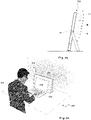
- the Figures 3a and 3b first illustrate the light emission A by the first light emission means 30, which are arranged on the front side 11 of the lighting fixture 10. It is shown in Figure 3a the situation of the use of the lamp 100 at a workplace 200, which can be formed, for example, by a simple table, on the surface of which a laptop 250 used for work is placed, on the back of which the lamp 100 according to the invention is arranged. Furthermore, in Figure 3a a person 260 using the workplace is shown.
- the first light emitting means 30 are provided to emit light towards the front via the frame-like surface area 35 in such a way that the work station 200 on which the laptop 250 is positioned, i.e. in particular the area of the table surface 210 surrounding the laptop 250, is illuminated .
- 250 placed in front of or next to the laptop Documents can be read better because of this lighting, especially when the ambient lighting does not provide sufficient light for this.
- a further effect of the light A emitted by the first light emission means 30 is that the person 260 himself is illuminated with a certain brightness. This is particularly advantageous when the laptop 250 is used to conduct video conferences and a camera image of the person 260 using the laptop 250 is to be captured for this purpose.
- the lighting provided at a home office workplace is often not sufficient for optimal video recording or the color temperature of the available light has a negative effect on the video recording.
- This problem is also efficiently solved with the aid of the first light emission means 30 since it is now ensured that an optimal image recording can be guaranteed due to the corresponding additional illumination.
- the light A emitted by the first light emitting means 30 also helps to avoid strong light contrasts. These could result in particular from the monitor luminance in a dark environment and make work significantly more difficult, since frequent and intensive adaptation of the human eye is required. By creating a luminous area surrounding the laptop screen 255, this problem is also reduced, creating a pleasant working atmosphere.
- the frame-like light emission area 35 of the first light emission means 30 is designed in such a way that it borders as closely as possible on the outer circumference of the laptop screen 255, but at least is not covered by it.
- the light emission area 35 should be dimensioned such that a screen 255 of common size (eg, a size of 16 inches represents a reasonable upper limit) fits in the area framed by the "C" pointing downwards. With smaller screen sizes, the distance between the screen 255 and the light emission area 35 would then increase, with a later A further development of the lamp 100 will be explained at the time, which here allows the light emission area 35 to be adjusted to a certain extent.
- the first light emission means 30 can be implemented in the most varied of ways.
- a corresponding matrix-like arrangement of LEDs on so-called backlight boards, preferably micro-LEDs would be conceivable, which would then be preceded by optical elements in the form of microprism optics, foils, diffusers and the like in order to convert punctiform LED light sources into a flat, homogeneously emitted light.
- OLEDs organic LEDs
- a preferred variant for realizing the first light-emitting means 30 consists in forming the frame-like light-emitting area 35 with suitably shaped, flat light guides, into which light is coupled via narrow sides and distributed uniformly by means of multiple reflections.
- a uniform light decoupling over the entire area 35 can then be achieved by appropriate light decoupling structures, for example in the form of microprisms, so that a completely homogeneous light emission is achieved over the U-shaped area.
- the realization of the first light emission means 30 using the just The light guide technology explained here also has the advantage that in this case the lighting means can be realized with a very small thickness, which has an advantageous effect on the dimensions, in particular the thickness of the lighting fixture 10 .
- first light emission means 30 are divided into a first part 30a located on the left side of the front side 11 and a second part 30b located on the right side. Both parts 30a, 30b can now be activated separately from one another for light emission or their intensity can be adjusted, with the result that, based on the two extreme situations, Figures 4a and 4b can be seen, then only the corresponding half of the work surface 210 and also the person 260 who is in front of the laptop 250 is only illuminated from the corresponding direction.
- This partial use of the first light emission means 30 can be desired in particular when the natural lighting situation of the workplace 200 includes natural lighting on one side. This can be the case, for example, if the workstation 200 is located on the side near a window through which natural daylight falls. At the in Figure 4a In the situation shown, it is therefore assumed that there is a window or another light source to the right of the workstation 200, while the opposite left side of the room is rather dark. In this case, it is advantageous if, to compensate for the natural incidence of light, only the left partial area is additionally illuminated with the aid of the first light emitting means 30, ie primarily the part 30a of the light emitting means 30 is activated. In the opposite case of Figure 4b however, only the second part 30b of the light emission means 30 is activated.
- a one-sided illumination of the person 260 can also be avoided here, which in the case of a video conference would lead to a strongly one-sided illumination and thus to a recording of very poor quality.
- the corresponding parts 30a and 30b of the first light emission means 30 are either completely switched on or off, but a corresponding adjustment of the respective intensities to achieve optimal illumination would also be conceivable.
- the two partial areas 35a and 35b of the light emission area 35 are preferably designed symmetrically to one another, with a sharp drop or jump in brightness not necessarily having to be present at the transition between the two partial areas.
- a simple and elegant way of realizing the two light-emitting means parts 30a and 30b would, for example, in the case of light guide technology, consist in arranging corresponding LEDs for light coupling on the two downward-pointing legs of the light-emitting area 35 and then only off depending on the desired lighting situation to couple light in the corresponding direction.
- this would result in the intensity of the light emitted over the upper horizontal area of the U-shaped light emission surface 35 gradually decreasing, starting from the active light coupling side, which leads to a further improved appearance.
- a strict subdivision would of course also be conceivable, particularly, for example, when using LEDs or OLEDs arranged in a matrix-like manner.
- the light A emitted by the first light emission means 30 therefore makes a decisive contribution to improving the lighting situation with regard to working on the laptop 20 in the area of the workstation 200 .
- additional light is preferably emitted with the aid of the lamp 100 according to the invention in order to further improve the lighting situation, which is to be explained in more detail below.
- further light emission means 40 are provided on the rear side 12 of the lighting fixture 10, which in the exemplary embodiment shown emit light B towards the rear over an approximately rectangular flat area 45.
- the area behind the laptop 250 or the lamp 100, in particular a wall 220 behind it, can be illuminated with the aid of the light B emitted by these additional light emitting means 40.
- This emission of light also leads to the correspondingly illuminated room surfaces having a contrast-reducing effect on the luminance of the monitor 255 of the laptop 250 . Overall, this contributes to a better appearance of the entire room and improves the working atmosphere.
- the second light emission means 40 can therefore only be seen indirectly by the user 260 .
- the second light emission means 40 could also be implemented in the form of strip-shaped light sources or LEDs arranged in a matrix. Since, despite everything, the area behind the laptop 250 should be illuminated with as few local brightness peaks as possible, it is also advantageous for these light sources 40 to emit light over as large an area as possible, which then, like the first light emitters 30, is preferably done with the help of fiber optic technology or also with can be realized with the other mentioned technologies.
- the particularly preferred embodiment of the lamp 100 also has third light emitting means 50 on the upper side 13 of the light emitting body 10, which are now designed as a strip-shaped light source extending almost over the entire length of the light emitting body 10 due to the space available.
- the light C emitted by these third light emission means 50 is directed upwards and is used in particular to illuminate a ceiling area of a room located above the workplace 200 in the sense of indirect lighting illuminate.
- a "cave effect" that can occur, for example, when there is insufficient ambient light and in turn makes the work situation more difficult, can be eliminated in this way. It would make sense for these third light emission means 50 to be implemented with the aid of an elongated LED circuit board, to which appropriate optics are assigned, in order to achieve a homogeneous elongated light emission.
- the light emission A, B, C of all three light emission means 30, 40 and 50 can be combined, as in FIGS Figures 7a and 7b is shown.
- an optimal lighting situation for a home office can be created by appropriate control of the various light emission means 30, 40 and 50.
- the luminaire 100 does not necessarily have to have the two further light emitting means 40 and 50 in addition to the first 30 light emitting means, although these also contribute to an improvement in the lighting situation, as explained above.
- the frame is selected in such a way that it essentially adjoins the outer circumference of the laptop monitor 255 without a border. If a laptop with a smaller display 255 is used instead, then there would be a larger distance between the outer edge of the display 255 and the Light emission area 35 result.
- the corresponding light emission means 30 it would now be conceivable to design the corresponding light emission means 30 in such a way that the thickness D of the frame (see figure 1 ) is enlarged (or the frame is even shifted) so that it is again almost flush with the outer circumference of the laptop monitor 255.
- This procedure is particularly useful when LEDs arranged in a matrix or OLED modules are used as light sources, since the shape of the area intended for light emission can be changed here in a relatively simple manner. Furthermore, it would be conceivable to dispense with the transverse upper area of the light emission area 35 and to implement the light emission of the first light emission means 30 exclusively by two vertical, flat light emission areas running laterally of the monitor.
- the design of the first light emission means 30 will be such that no light is emitted over the central area of the front side 11 of the lighting fixture 10, since this area is shaded by the laptop screen.
- This free space could now also be used for other purposes. For example, it would be conceivable to place a highly reflective mirror surface here. At times when the light 100 is not used for home office work, it could then be used as a make-up mirror, for example.
- the attachment of a simple display, e.g. for a time or temperature display, would also be conceivable. In principle, therefore, this area that is not used for lighting purposes can be used to give the luminaire 100 an additional benefit that goes beyond the lighting.
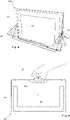
- the inclination of the bracket 20 can, as already mentioned and as based on figure 8 once again clarified, in order to suitably adjust the inclination of the luminaire 100 in the event that it is resting on a horizontal surface. In principle, however, it would also be conceivable to use the bracket 20 for a corresponding installation on a wall, to which the luminaire 100 is then permanently attached, although its inclination can in turn be adjusted accordingly.
- bracket 20 being completely parallel to the plane of the panel-like lighting fixture 10 to align
- a slightly trapezoidal recess 14a is provided on the underside 14 of the lighting fixture 10 opens up the possibility in this case of using the bracket 20 as a handle and of transporting the lamp 100 in a simple manner.
- the luminaire 100 according to the invention is preferably designed to be operated at least temporarily without an external energy supply source.
- the lamp 100 preferably has internal energy storage means in the form of accumulators or the like.
- An external power supply is provided with the help of an in figure 10 illustrated, lateral connection allows 18, which, for example. Allows connection to a power supply cable 270.
- this can be designed according to the USB-C standard and either lead to an external power supply unit or be used to connect the lamp 100 directly to a laptop. In this case, the connection to the laptop then enables the lamp 100 to be operated in a convenient manner without additional external energy supply means.
- connection option shown is to use the connection to a laptop to also control the light 100.
- a special user interface could be provided for this, with which the intensity of the individual light emitting means 30, 40, 50 (and possibly the corresponding parts 35a and 35b in the case of the first light emitting means 30) as well as the color or color temperature of the emitted light can be adjusted.
- Automated or partially automated control, in particular of the first light emission means 30, can also be carried out, for example, by taking a corresponding picture using the laptop camera and optimizing the intensity and color temperature of the emitted light in a coordinated manner.
- a comparable user interface for controlling the lamp 100 and for setting the various lighting parameters could also be provided using a corresponding app on a mobile device, in particular a mobile phone 300, as is shown in figure 11 is shown. This is then wirelessly coupled via a corresponding communication link with the lamp 100 to a to be able to carry out comfortable control. Finally, of course, there would also be the possibility of attaching corresponding control elements to the luminaire 100 itself, which would enable manual adjustment of the light output.
- the housing of the lamp 100 is formed by the housing of the lighting fixture 10 and is formed, for example, from powdered steel or sheet aluminum, which gives the lamp 100 an extremely attractive appearance. It would be conceivable to make the outer shell of the lighting fixture 10 removable and then to provide different shells that allow the user to adapt the lamp 100 in terms of its outer design in a similar way to mobile phones.
- the covers, which can then be snapped or latched onto the lighting fixture 10 can differ in terms of their color and the material used, with felt, wood, thick fabric, composite plastics, silicone, etc. being conceivable as materials.
- the present invention provides a new type of light that solves a large number of tasks in modern lighting technology with regard to the illumination of workplaces, particularly in the home office area, in a simple and elegant manner.
- the lamp is characterized by its elegant structure and its flexible application options.
Landscapes
- Engineering & Computer Science (AREA)
- General Engineering & Computer Science (AREA)
- Multimedia (AREA)
- Non-Portable Lighting Devices Or Systems Thereof (AREA)
- Fastening Of Light Sources Or Lamp Holders (AREA)
Applications Claiming Priority (1)
| Application Number | Priority Date | Filing Date | Title |
|---|---|---|---|
| DE102021110220.0A DE102021110220A1 (de) | 2021-04-22 | 2021-04-22 | Multifunktionale Leuchte zur Beleuchtung eines Arbeitsplatzes |
Publications (2)
| Publication Number | Publication Date |
|---|---|
| EP4080109A1 true EP4080109A1 (fr) | 2022-10-26 |
| EP4080109B1 EP4080109B1 (fr) | 2025-01-01 |
Family
ID=81454633
Family Applications (1)
| Application Number | Title | Priority Date | Filing Date |
|---|---|---|---|
| EP22169165.2A Active EP4080109B1 (fr) | 2021-04-22 | 2022-04-21 | Luminaire multifonction destiné à l'éclairage d'un poste de travail |
Country Status (3)
| Country | Link |
|---|---|
| EP (1) | EP4080109B1 (fr) |
| AT (1) | AT18636U1 (fr) |
| DE (1) | DE102021110220A1 (fr) |
Citations (7)
| Publication number | Priority date | Publication date | Assignee | Title |
|---|---|---|---|---|
| US5777704A (en) * | 1996-10-30 | 1998-07-07 | International Business Machines Corporation | Backlighting an LCD-based notebook computer under varying ambient light conditions |
| EP0855552A2 (fr) * | 1997-01-23 | 1998-07-29 | Zumtobel Staff GmbH | Dispositif d'éclairage pour poste de travail |
| DE20021973U1 (de) * | 2000-12-28 | 2001-03-22 | Wang Kuang Ting | Bilderrahmenartige Nachtlampe |
| DE20023069U1 (de) * | 2000-06-21 | 2002-11-21 | Sonlux Licht- und Elektroinstallation GmbH & Co. KG Sondershausen, 99706 Sondershausen | Arbeitsleuchte |
| WO2007026285A1 (fr) * | 2005-08-30 | 2007-03-08 | Koninklijke Philips Electronics, N.V. | Lumiere ambiante pour ecrans d'affichage a travers des materiaux transparents |
| CN104633585A (zh) * | 2014-12-30 | 2015-05-20 | 合肥宝丽环保科技有限公司 | 一种太阳能相框式台灯 |
| US20160153650A1 (en) * | 2010-11-19 | 2016-06-02 | Tseng-Lu Chien | Led desk light having more than one function |
Family Cites Families (5)
| Publication number | Priority date | Publication date | Assignee | Title |
|---|---|---|---|---|
| DE20010657U1 (de) | 2000-06-21 | 2001-10-31 | Sonlux Licht- und Elektroinstallation GmbH & Co. KG Sondershausen, 99706 Sondershausen | Arbeitsleuchte |
| EP1551178A1 (fr) | 2003-12-18 | 2005-07-06 | Koninklijke Philips Electronics N.V. | Système supplémentaire d'affichage visuel |
| WO2005088390A1 (fr) | 2004-03-08 | 2005-09-22 | Koninklijke Philips Electronics N.V. | Dispositif d'affichage |
| EP1763955A1 (fr) | 2004-06-30 | 2007-03-21 | Koninklijke Philips Electronics N.V. | Systeme d'encadrement de diffuseur passif pour la lumiere ambiante utilisant un unite d'affichage video comme source lumineuse |
| JP2012238552A (ja) | 2011-05-13 | 2012-12-06 | Konica Minolta Advanced Layers Inc | 照明付き鏡 |
-
2021
- 2021-04-22 DE DE102021110220.0A patent/DE102021110220A1/de active Pending
- 2021-08-11 AT ATGM50169/2021U patent/AT18636U1/de unknown
-
2022
- 2022-04-21 EP EP22169165.2A patent/EP4080109B1/fr active Active
Patent Citations (7)
| Publication number | Priority date | Publication date | Assignee | Title |
|---|---|---|---|---|
| US5777704A (en) * | 1996-10-30 | 1998-07-07 | International Business Machines Corporation | Backlighting an LCD-based notebook computer under varying ambient light conditions |
| EP0855552A2 (fr) * | 1997-01-23 | 1998-07-29 | Zumtobel Staff GmbH | Dispositif d'éclairage pour poste de travail |
| DE20023069U1 (de) * | 2000-06-21 | 2002-11-21 | Sonlux Licht- und Elektroinstallation GmbH & Co. KG Sondershausen, 99706 Sondershausen | Arbeitsleuchte |
| DE20021973U1 (de) * | 2000-12-28 | 2001-03-22 | Wang Kuang Ting | Bilderrahmenartige Nachtlampe |
| WO2007026285A1 (fr) * | 2005-08-30 | 2007-03-08 | Koninklijke Philips Electronics, N.V. | Lumiere ambiante pour ecrans d'affichage a travers des materiaux transparents |
| US20160153650A1 (en) * | 2010-11-19 | 2016-06-02 | Tseng-Lu Chien | Led desk light having more than one function |
| CN104633585A (zh) * | 2014-12-30 | 2015-05-20 | 合肥宝丽环保科技有限公司 | 一种太阳能相框式台灯 |
Also Published As
| Publication number | Publication date |
|---|---|
| EP4080109B1 (fr) | 2025-01-01 |
| AT18636U1 (de) | 2026-02-15 |
| DE102021110220A1 (de) | 2022-10-27 |
Similar Documents
| Publication | Publication Date | Title |
|---|---|---|
| EP2239494B1 (fr) | Agencement destiné à l'éclairage ambiant | |
| EP2039984B1 (fr) | Dispositif d'éclairage pour une unité d'entretien médicale | |
| EP1568935A1 (fr) | Lampe chirurgicale | |
| DE112006002976T5 (de) | Beleuchtungsvorrichtung | |
| WO2001059364A1 (fr) | Appareil d'eclairage | |
| DE102016124257B4 (de) | Leuchte | |
| DE10006409A1 (de) | Leuchte | |
| EP4080109B1 (fr) | Luminaire multifonction destiné à l'éclairage d'un poste de travail | |
| DE19606072A1 (de) | Videopräsentator | |
| EP4129114B1 (fr) | Poste mobile de travail | |
| DE102011004882B4 (de) | Leuchteinheit mit Beleuchtungseinheit und Projektionseinheit | |
| EP4130550B1 (fr) | Luminaire d'éclairage d'un poste de travail | |
| AT16738U1 (de) | Anordnung zur Lichtabgabe | |
| DE202012004264U1 (de) | Lichttherapievorrichtung | |
| DE10056745A1 (de) | Leuchte mit farbigem Indirekt-Lichtanteil | |
| DE10224421A1 (de) | Lichtwand | |
| DE4109189A1 (de) | Einrichtung zur indirekten beleuchtung | |
| DE20205233U1 (de) | Leichtbau-Stahlrahmen-Leuchtenanordnung | |
| EP2281397B1 (fr) | Dispositif d éclairage et d affichage | |
| DE1939213C3 (de) | Anordnung zum bildmäßigen Aufnehmen des Leseverhaltens einer Person | |
| DE60018129T2 (de) | Beleuchtungseinrichtung mit ausgeprägten Blendeschutz-Eigenschaften | |
| EP2518387B1 (fr) | Feu de position | |
| EP1045196A2 (fr) | Dispositif d'éclairage avec une structure porteuse | |
| EP4166841A1 (fr) | Luminaire extérieur à éclairage ambiant contrôlable | |
| DE202021103014U1 (de) | Leuchtvorrichtung |
Legal Events
| Date | Code | Title | Description |
|---|---|---|---|
| PUAI | Public reference made under article 153(3) epc to a published international application that has entered the european phase |
Free format text: ORIGINAL CODE: 0009012 |
|
| STAA | Information on the status of an ep patent application or granted ep patent |
Free format text: STATUS: THE APPLICATION HAS BEEN PUBLISHED |
|
| AK | Designated contracting states |
Kind code of ref document: A1 Designated state(s): AL AT BE BG CH CY CZ DE DK EE ES FI FR GB GR HR HU IE IS IT LI LT LU LV MC MK MT NL NO PL PT RO RS SE SI SK SM TR |
|
| STAA | Information on the status of an ep patent application or granted ep patent |
Free format text: STATUS: REQUEST FOR EXAMINATION WAS MADE |
|
| 17P | Request for examination filed |
Effective date: 20230116 |
|
| RBV | Designated contracting states (corrected) |
Designated state(s): AL AT BE BG CH CY CZ DE DK EE ES FI FR GB GR HR HU IE IS IT LI LT LU LV MC MK MT NL NO PL PT RO RS SE SI SK SM TR |
|
| GRAP | Despatch of communication of intention to grant a patent |
Free format text: ORIGINAL CODE: EPIDOSNIGR1 |
|
| STAA | Information on the status of an ep patent application or granted ep patent |
Free format text: STATUS: GRANT OF PATENT IS INTENDED |
|
| RIC1 | Information provided on ipc code assigned before grant |
Ipc: F21W 131/402 20060101ALN20240906BHEP Ipc: F21S 10/02 20060101ALI20240906BHEP Ipc: F21V 21/10 20060101ALI20240906BHEP Ipc: F21V 21/30 20060101ALI20240906BHEP Ipc: F21V 33/00 20060101ALI20240906BHEP Ipc: F21V 23/04 20060101ALI20240906BHEP Ipc: F21S 9/02 20060101ALI20240906BHEP Ipc: F21S 6/00 20060101AFI20240906BHEP |
|
| INTG | Intention to grant announced |
Effective date: 20240930 |
|
| GRAS | Grant fee paid |
Free format text: ORIGINAL CODE: EPIDOSNIGR3 |
|
| GRAA | (expected) grant |
Free format text: ORIGINAL CODE: 0009210 |
|
| STAA | Information on the status of an ep patent application or granted ep patent |
Free format text: STATUS: THE PATENT HAS BEEN GRANTED |
|
| AK | Designated contracting states |
Kind code of ref document: B1 Designated state(s): AL AT BE BG CH CY CZ DE DK EE ES FI FR GB GR HR HU IE IS IT LI LT LU LV MC MK MT NL NO PL PT RO RS SE SI SK SM TR |
|
| REG | Reference to a national code |
Ref country code: GB Ref legal event code: FG4D Free format text: NOT ENGLISH |
|
| P01 | Opt-out of the competence of the unified patent court (upc) registered |
Free format text: CASE NUMBER: APP_63502/2024 Effective date: 20241129 |
|
| REG | Reference to a national code |
Ref country code: CH Ref legal event code: EP |
|
| REG | Reference to a national code |
Ref country code: DE Ref legal event code: R096 Ref document number: 502022002548 Country of ref document: DE |
|
| REG | Reference to a national code |
Ref country code: IE Ref legal event code: FG4D Free format text: LANGUAGE OF EP DOCUMENT: GERMAN |
|
| REG | Reference to a national code |
Ref country code: DE Ref legal event code: R084 Ref document number: 502022002548 Country of ref document: DE |
|
| REG | Reference to a national code |
Ref country code: LT Ref legal event code: MG9D |
|
| REG | Reference to a national code |
Ref country code: NL Ref legal event code: MP Effective date: 20250101 |
|
| PG25 | Lapsed in a contracting state [announced via postgrant information from national office to epo] |
Ref country code: NL Free format text: LAPSE BECAUSE OF FAILURE TO SUBMIT A TRANSLATION OF THE DESCRIPTION OR TO PAY THE FEE WITHIN THE PRESCRIBED TIME-LIMIT Effective date: 20250101 |
|
| PG25 | Lapsed in a contracting state [announced via postgrant information from national office to epo] |
Ref country code: FI Free format text: LAPSE BECAUSE OF FAILURE TO SUBMIT A TRANSLATION OF THE DESCRIPTION OR TO PAY THE FEE WITHIN THE PRESCRIBED TIME-LIMIT Effective date: 20250101 |
|
| PG25 | Lapsed in a contracting state [announced via postgrant information from national office to epo] |
Ref country code: PL Free format text: LAPSE BECAUSE OF FAILURE TO SUBMIT A TRANSLATION OF THE DESCRIPTION OR TO PAY THE FEE WITHIN THE PRESCRIBED TIME-LIMIT Effective date: 20250101 |
|
| PGFP | Annual fee paid to national office [announced via postgrant information from national office to epo] |
Ref country code: DE Payment date: 20250428 Year of fee payment: 4 |
|
| PG25 | Lapsed in a contracting state [announced via postgrant information from national office to epo] |
Ref country code: ES Free format text: LAPSE BECAUSE OF FAILURE TO SUBMIT A TRANSLATION OF THE DESCRIPTION OR TO PAY THE FEE WITHIN THE PRESCRIBED TIME-LIMIT Effective date: 20250101 |
|
| PG25 | Lapsed in a contracting state [announced via postgrant information from national office to epo] |
Ref country code: NO Free format text: LAPSE BECAUSE OF FAILURE TO SUBMIT A TRANSLATION OF THE DESCRIPTION OR TO PAY THE FEE WITHIN THE PRESCRIBED TIME-LIMIT Effective date: 20250401 Ref country code: IS Free format text: LAPSE BECAUSE OF FAILURE TO SUBMIT A TRANSLATION OF THE DESCRIPTION OR TO PAY THE FEE WITHIN THE PRESCRIBED TIME-LIMIT Effective date: 20250501 |
|
| PG25 | Lapsed in a contracting state [announced via postgrant information from national office to epo] |
Ref country code: HR Free format text: LAPSE BECAUSE OF FAILURE TO SUBMIT A TRANSLATION OF THE DESCRIPTION OR TO PAY THE FEE WITHIN THE PRESCRIBED TIME-LIMIT Effective date: 20250101 |
|
| PG25 | Lapsed in a contracting state [announced via postgrant information from national office to epo] |
Ref country code: PT Free format text: LAPSE BECAUSE OF FAILURE TO SUBMIT A TRANSLATION OF THE DESCRIPTION OR TO PAY THE FEE WITHIN THE PRESCRIBED TIME-LIMIT Effective date: 20250502 Ref country code: LV Free format text: LAPSE BECAUSE OF FAILURE TO SUBMIT A TRANSLATION OF THE DESCRIPTION OR TO PAY THE FEE WITHIN THE PRESCRIBED TIME-LIMIT Effective date: 20250101 |
|
| PGFP | Annual fee paid to national office [announced via postgrant information from national office to epo] |
Ref country code: FR Payment date: 20250424 Year of fee payment: 4 |
|
| PG25 | Lapsed in a contracting state [announced via postgrant information from national office to epo] |
Ref country code: GR Free format text: LAPSE BECAUSE OF FAILURE TO SUBMIT A TRANSLATION OF THE DESCRIPTION OR TO PAY THE FEE WITHIN THE PRESCRIBED TIME-LIMIT Effective date: 20250402 Ref country code: BG Free format text: LAPSE BECAUSE OF FAILURE TO SUBMIT A TRANSLATION OF THE DESCRIPTION OR TO PAY THE FEE WITHIN THE PRESCRIBED TIME-LIMIT Effective date: 20250101 |
|
| PGFP | Annual fee paid to national office [announced via postgrant information from national office to epo] |
Ref country code: AT Payment date: 20250721 Year of fee payment: 4 |
|
| PG25 | Lapsed in a contracting state [announced via postgrant information from national office to epo] |
Ref country code: CZ Free format text: LAPSE BECAUSE OF FAILURE TO SUBMIT A TRANSLATION OF THE DESCRIPTION OR TO PAY THE FEE WITHIN THE PRESCRIBED TIME-LIMIT Effective date: 20250101 |
|
| PG25 | Lapsed in a contracting state [announced via postgrant information from national office to epo] |
Ref country code: SE Free format text: LAPSE BECAUSE OF FAILURE TO SUBMIT A TRANSLATION OF THE DESCRIPTION OR TO PAY THE FEE WITHIN THE PRESCRIBED TIME-LIMIT Effective date: 20250101 |
|
| REG | Reference to a national code |
Ref country code: DE Ref legal event code: R097 Ref document number: 502022002548 Country of ref document: DE |
|
| PG25 | Lapsed in a contracting state [announced via postgrant information from national office to epo] |
Ref country code: SM Free format text: LAPSE BECAUSE OF FAILURE TO SUBMIT A TRANSLATION OF THE DESCRIPTION OR TO PAY THE FEE WITHIN THE PRESCRIBED TIME-LIMIT Effective date: 20250101 |
|
| PG25 | Lapsed in a contracting state [announced via postgrant information from national office to epo] |
Ref country code: DK Free format text: LAPSE BECAUSE OF FAILURE TO SUBMIT A TRANSLATION OF THE DESCRIPTION OR TO PAY THE FEE WITHIN THE PRESCRIBED TIME-LIMIT Effective date: 20250101 |
|
| PG25 | Lapsed in a contracting state [announced via postgrant information from national office to epo] |
Ref country code: IT Free format text: LAPSE BECAUSE OF FAILURE TO SUBMIT A TRANSLATION OF THE DESCRIPTION OR TO PAY THE FEE WITHIN THE PRESCRIBED TIME-LIMIT Effective date: 20250101 |
|
| PG25 | Lapsed in a contracting state [announced via postgrant information from national office to epo] |
Ref country code: EE Free format text: LAPSE BECAUSE OF FAILURE TO SUBMIT A TRANSLATION OF THE DESCRIPTION OR TO PAY THE FEE WITHIN THE PRESCRIBED TIME-LIMIT Effective date: 20250101 |
|
| PG25 | Lapsed in a contracting state [announced via postgrant information from national office to epo] |
Ref country code: RO Free format text: LAPSE BECAUSE OF FAILURE TO SUBMIT A TRANSLATION OF THE DESCRIPTION OR TO PAY THE FEE WITHIN THE PRESCRIBED TIME-LIMIT Effective date: 20250101 |
|
| PG25 | Lapsed in a contracting state [announced via postgrant information from national office to epo] |
Ref country code: SK Free format text: LAPSE BECAUSE OF FAILURE TO SUBMIT A TRANSLATION OF THE DESCRIPTION OR TO PAY THE FEE WITHIN THE PRESCRIBED TIME-LIMIT Effective date: 20250101 |
|
| PLBE | No opposition filed within time limit |
Free format text: ORIGINAL CODE: 0009261 |
|
| STAA | Information on the status of an ep patent application or granted ep patent |
Free format text: STATUS: NO OPPOSITION FILED WITHIN TIME LIMIT |
|
| REG | Reference to a national code |
Ref country code: CH Ref legal event code: L10 Free format text: ST27 STATUS EVENT CODE: U-0-0-L10-L00 (AS PROVIDED BY THE NATIONAL OFFICE) Effective date: 20251112 |
|
| REG | Reference to a national code |
Ref country code: CH Ref legal event code: H13 Free format text: ST27 STATUS EVENT CODE: U-0-0-H10-H13 (AS PROVIDED BY THE NATIONAL OFFICE) Effective date: 20251125 |
|
| 26N | No opposition filed |
Effective date: 20251002 |
|
| PG25 | Lapsed in a contracting state [announced via postgrant information from national office to epo] |
Ref country code: LU Free format text: LAPSE BECAUSE OF NON-PAYMENT OF DUE FEES Effective date: 20250421 |
|
| PG25 | Lapsed in a contracting state [announced via postgrant information from national office to epo] |
Ref country code: MC Free format text: LAPSE BECAUSE OF FAILURE TO SUBMIT A TRANSLATION OF THE DESCRIPTION OR TO PAY THE FEE WITHIN THE PRESCRIBED TIME-LIMIT Effective date: 20250101 |
|
| REG | Reference to a national code |
Ref country code: BE Ref legal event code: MM Effective date: 20250430 |
|
| PG25 | Lapsed in a contracting state [announced via postgrant information from national office to epo] |
Ref country code: BE Free format text: LAPSE BECAUSE OF NON-PAYMENT OF DUE FEES Effective date: 20250430 |
|
| PG25 | Lapsed in a contracting state [announced via postgrant information from national office to epo] |
Ref country code: CH Free format text: LAPSE BECAUSE OF NON-PAYMENT OF DUE FEES Effective date: 20250430 |
|
| PGFP | Annual fee paid to national office [announced via postgrant information from national office to epo] |
Ref country code: GB Payment date: 20260304 Year of fee payment: 5 |
|
| PG25 | Lapsed in a contracting state [announced via postgrant information from national office to epo] |
Ref country code: IE Free format text: LAPSE BECAUSE OF NON-PAYMENT OF DUE FEES Effective date: 20250421 |