EP4080224A1 - Capteur d'accélération, procédé d'évaluation d'accélération l'utilisant, et charge équipée d'un capteur d'accélération - Google Patents
Capteur d'accélération, procédé d'évaluation d'accélération l'utilisant, et charge équipée d'un capteur d'accélération Download PDFInfo
- Publication number
- EP4080224A1 EP4080224A1 EP20901556.9A EP20901556A EP4080224A1 EP 4080224 A1 EP4080224 A1 EP 4080224A1 EP 20901556 A EP20901556 A EP 20901556A EP 4080224 A1 EP4080224 A1 EP 4080224A1
- Authority
- EP
- European Patent Office
- Prior art keywords
- acceleration
- acceleration sensor
- plate
- color
- silver nanowire
- Prior art date
- Legal status (The legal status is an assumption and is not a legal conclusion. Google has not performed a legal analysis and makes no representation as to the accuracy of the status listed.)
- Withdrawn
Links
- 230000001133 acceleration Effects 0.000 title claims abstract description 103
- 238000011156 evaluation Methods 0.000 title claims description 23
- BQCADISMDOOEFD-UHFFFAOYSA-N Silver Chemical compound [Ag] BQCADISMDOOEFD-UHFFFAOYSA-N 0.000 claims abstract description 47
- 239000002042 Silver nanowire Substances 0.000 claims description 10
- XLYOFNOQVPJJNP-UHFFFAOYSA-N water Substances O XLYOFNOQVPJJNP-UHFFFAOYSA-N 0.000 claims description 6
- 239000002904 solvent Substances 0.000 claims description 4
- 239000006185 dispersion Substances 0.000 description 16
- 230000003287 optical effect Effects 0.000 description 8
- 238000000034 method Methods 0.000 description 7
- 238000002834 transmittance Methods 0.000 description 6
- 241000974482 Aricia saepiolus Species 0.000 description 3
- 230000000052 comparative effect Effects 0.000 description 3
- LFQSCWFLJHTTHZ-UHFFFAOYSA-N Ethanol Chemical compound CCO LFQSCWFLJHTTHZ-UHFFFAOYSA-N 0.000 description 2
- 230000010287 polarization Effects 0.000 description 2
- 230000005540 biological transmission Effects 0.000 description 1
- 239000003990 capacitor Substances 0.000 description 1
- 238000010586 diagram Methods 0.000 description 1
- 230000000694 effects Effects 0.000 description 1
- 239000007788 liquid Substances 0.000 description 1
- 239000000463 material Substances 0.000 description 1
- 239000000203 mixture Substances 0.000 description 1
- 239000003960 organic solvent Substances 0.000 description 1
- -1 quantity Substances 0.000 description 1
- 230000035945 sensitivity Effects 0.000 description 1
- 239000004094 surface-active agent Substances 0.000 description 1
Images
Classifications
-
- G—PHYSICS
- G01—MEASURING; TESTING
- G01P—MEASURING LINEAR OR ANGULAR SPEED, ACCELERATION, DECELERATION, OR SHOCK; INDICATING PRESENCE, ABSENCE, OR DIRECTION, OF MOVEMENT
- G01P15/00—Measuring acceleration; Measuring deceleration; Measuring shock, i.e. sudden change of acceleration
- G01P15/02—Measuring acceleration; Measuring deceleration; Measuring shock, i.e. sudden change of acceleration by making use of inertia forces using solid seismic masses
- G01P15/03—Measuring acceleration; Measuring deceleration; Measuring shock, i.e. sudden change of acceleration by making use of inertia forces using solid seismic masses by using non-electrical means
-
- G—PHYSICS
- G01—MEASURING; TESTING
- G01P—MEASURING LINEAR OR ANGULAR SPEED, ACCELERATION, DECELERATION, OR SHOCK; INDICATING PRESENCE, ABSENCE, OR DIRECTION, OF MOVEMENT
- G01P15/00—Measuring acceleration; Measuring deceleration; Measuring shock, i.e. sudden change of acceleration
- G01P15/02—Measuring acceleration; Measuring deceleration; Measuring shock, i.e. sudden change of acceleration by making use of inertia forces using solid seismic masses
- G01P15/08—Measuring acceleration; Measuring deceleration; Measuring shock, i.e. sudden change of acceleration by making use of inertia forces using solid seismic masses with conversion into electric or magnetic values
- G01P15/093—Measuring acceleration; Measuring deceleration; Measuring shock, i.e. sudden change of acceleration by making use of inertia forces using solid seismic masses with conversion into electric or magnetic values by photoelectric pick-up
-
- G—PHYSICS
- G01—MEASURING; TESTING
- G01J—MEASUREMENT OF INTENSITY, VELOCITY, SPECTRAL CONTENT, POLARISATION, PHASE OR PULSE CHARACTERISTICS OF INFRARED, VISIBLE OR ULTRAVIOLET LIGHT; COLORIMETRY; RADIATION PYROMETRY
- G01J3/00—Spectrometry; Spectrophotometry; Monochromators; Measuring colours
- G01J3/02—Details
- G01J3/0205—Optical elements not provided otherwise, e.g. optical manifolds, diffusers, windows
- G01J3/0224—Optical elements not provided otherwise, e.g. optical manifolds, diffusers, windows using polarising or depolarising elements
-
- G—PHYSICS
- G01—MEASURING; TESTING
- G01J—MEASUREMENT OF INTENSITY, VELOCITY, SPECTRAL CONTENT, POLARISATION, PHASE OR PULSE CHARACTERISTICS OF INFRARED, VISIBLE OR ULTRAVIOLET LIGHT; COLORIMETRY; RADIATION PYROMETRY
- G01J3/00—Spectrometry; Spectrophotometry; Monochromators; Measuring colours
- G01J3/46—Measurement of colour; Colour measuring devices, e.g. colorimeters
-
- G—PHYSICS
- G01—MEASURING; TESTING
- G01J—MEASUREMENT OF INTENSITY, VELOCITY, SPECTRAL CONTENT, POLARISATION, PHASE OR PULSE CHARACTERISTICS OF INFRARED, VISIBLE OR ULTRAVIOLET LIGHT; COLORIMETRY; RADIATION PYROMETRY
- G01J4/00—Measuring polarisation of light
-
- G—PHYSICS
- G01—MEASURING; TESTING
- G01P—MEASURING LINEAR OR ANGULAR SPEED, ACCELERATION, DECELERATION, OR SHOCK; INDICATING PRESENCE, ABSENCE, OR DIRECTION, OF MOVEMENT
- G01P15/00—Measuring acceleration; Measuring deceleration; Measuring shock, i.e. sudden change of acceleration
- G01P15/02—Measuring acceleration; Measuring deceleration; Measuring shock, i.e. sudden change of acceleration by making use of inertia forces using solid seismic masses
- G01P15/03—Measuring acceleration; Measuring deceleration; Measuring shock, i.e. sudden change of acceleration by making use of inertia forces using solid seismic masses by using non-electrical means
- G01P15/038—Measuring acceleration; Measuring deceleration; Measuring shock, i.e. sudden change of acceleration by making use of inertia forces using solid seismic masses by using non-electrical means by using fluidic means
Definitions
- the present invention relates to an acceleration sensor, an acceleration evaluation method using the same, and a load provided with the acceleration sensor.
- an electrostatic capacitance method, a piezo resistance method, or the like is used for an acceleration sensor.
- the electrostatic capacitance method is used in which one electrode of a capacitor inside a sensor is used as a movable portion and a change in response to the acceleration thereof is electrically read from a change in the electrostatic capacitance.
- the piezo resistance method is used in which a resistance change of a strain gauge is electrically read and the acceleration is calculated.
- acceleration information can be obtained from electronic information. Therefore, in order to check the acceleration with the acceleration sensor in the related art, an electronic analysis of the acceleration information is required, which requires electric power consumption.
- An object of the present invention is to provide an acceleration sensor capable of visually evaluating acceleration without requiring electric power consumption.
- first to third aspects of the present invention have the following configurations.
- acceleration can be visually evaluated without requiring electric power consumption.
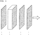
- Fig. 1 is a diagram schematically showing the disposition of two polarizing plates, a sensitive color plate, and a silver nanowire dispersion.
- the arrow in the figure indicates an optical axis direction.
- a sensitive color plate 2 is provided between two polarizing plates 1 and 4 that are in a crossed Nicol disposition, and a silver nanowire dispersion 3 is further provided between the polarizing plate 4 and the sensitive color plate 2.
- the polarizing plate 1 and the polarizing plate 4 are disposed such that transmission axes are orthogonal to each other.
- the silver nanowire dispersion 3 may be disposed between the polarizing plate 1 and the sensitive color plate 2.
- the silver nanowire dispersion 3 and the sensitive color plate 2 can be disposed in any order.
- the sensitive color plate 2 is, for example, a phase difference plate.
- the silver nanowire dispersion is a dispersion in which silver nanowires are dispersed in a solvent.
- Fig. 1 shows an example in which the silver nanowire dispersion is contained in a transparent container.
- the silver nanowire dispersion 3 may be referred to as dispersion 3.
- the silver nanowires in the dispersion 3 have the property of being oriented along an acceleration direction.
- the acceleration sensor of the present embodiment uses this property to detect the orientation of the silver nanowires by using a sensitive color plate method.
- two polarizing plates and a phase difference plate are disposed so as to be perpendicular to the optical axis of white light incident from a white light source (hereinafter, may be simply referred to as an "optical axis"). That is, the polarizing plate and the phase difference plate are disposed in parallel.
- the phase difference plate uses a single wavelength plate.
- the phase difference plate is used as the sensitive color plate 2 by disposing the fast axis (or slow axis) of the phase difference plate at an angle of 45° with respect to a polarization axis of the polarizing plate when viewed from the optical axis direction.
- the sensitive color plate 2 preferably has a phase difference of 530 nm or more and 580 nm or less so that the color change can be easily seen with the naked eye.
- the sensitive color plate will be described using such a sensitive color plate 2. Further, the expression of the color name conforms to Japanese Industrial Standards JIS Z 8102:2001.
- the sensitive color plate In the crossed Nicol state, when observed with only two polarizing plates, the light beam is blocked and it becomes dark. Further, the sensitive color plate has a fast axis direction and a slow axis direction. When the sensitive color plate is disposed between the two polarizing plates combined at orthogonal positions, it shows a vivid color as an interference color, and the interference color changes sensitively when the phase difference changes even slightly.
- Examples of a medium (solvent) of the silver nanowire dispersion 3 include an organic solvent such as ethanol and water, and water is preferable from the viewpoint of ease of handling.
- a surfactant or the like may be added to the silver nanowire dispersion 3 in order to obtain a stable dispersion.
- the silver nanowire dispersion 3 be contained in a transparent container because it is easy to handle.
- the transparent container may independently contain the silver nanowire dispersion 3 or may contain the silver nanowire dispersion 3 in combination with other members.
- one polarizing plate of the polarizing plates 1 and 4 and the sensitive color plate 2 may be used as a part of a wall of the container for containing the silver nanowire dispersion 3.
- the shape of the silver nanowire dispersion is the shape of the inside of the container.
- the thinner one can reduce the size of the acceleration sensor, the thicker one can dilute the dispersion 3 as described later so that the dispersion 3 is stably dispersed.
- the thickness of the silver nanowire dispersion 3 is preferably 0.2 mm or more and 5 mm or less, more preferably 0.3 mm or more and 3 mm or less, and even more preferably 0.5 mm or more and 2 mm or less.
- the concentration of the silver nanowires in the dispersion 3 depends on the thickness of the dispersion 3.
- the concentration of the silver nanowires in the dispersion 3 may become high concentration when the thickness of the dispersion 3 is thin and may become low concentration when the thickness of the dispersion 3 is thick. Therefore, a product of the concentration (% by mass) of the silver nanowires in the dispersion 3 and the thickness (mm) of the dispersion 3 may be used as an index.
- the product is preferably 0.01% by mass x mm or more and 1% by mass x mm or less, more preferably 0.03% by mass x mm or more and 0.5% by mass x mm or less, and even more preferably 0.1% by mass x mm or more and 0.3% by mass x mm or less.
- an acceleration evaluation method of the present embodiment by using the acceleration sensor, white light is allowed to be incident from an outside of one polarizing plate, and a color of light emitted from an outside of the other polarizing plate is observed. That is, in the acceleration evaluation method of the present embodiment, for example, when the white light is incident perpendicularly to the polarizing plate 1, the color of the acceleration sensor observed from the polarizing plate 4 side, more specifically, the color of the silver nanowire dispersion 3 is evaluated via the polarizing plate 4.
- the light source of the white light may include light of a color that can be easily distinguished by the sensitive color plate 2 to be used, and examples thereof include natural light such as sunlight and artificial light such as an incandescent lamp, a fluorescent lamp, and an LED lamp. Since the light source of the white light may be natural light, the acceleration sensor of the present embodiment does not require electric power. Further, even when the light source of the white light is artificial light, the originally provided indoor lighting can be used, and from such a viewpoint, the acceleration sensor of the present embodiment does not require new electric power.
- the acceleration direction is evaluated to be the fast axis direction of the sensitive color plate. Further, when the observed color of light is a color included in a range of red to orange, the acceleration direction is evaluated to be the slow axis direction of the sensitive color plate, and reddish-purple such as magenta may be partially included.
- the observed color is a color included in a range of blue to bluish-purple, although there is a possibility of accelerating in the optical axis direction (perpendicular direction to the polarizing plate or the sensitive color plate), in the present embodiment, it may be evaluated that there is no acceleration. This is because the acceleration direction detected in the present embodiment is a direction represented in two dimensions in a plane perpendicular to the optical axis unless otherwise specified.
- the acceleration sensor of the present embodiment when the viscosity of the silver nanowire dispersion to be used is high, the response to acceleration becomes slow, and conversely, when the viscosity is low, the response becomes fast.
- the response time of the acceleration sensor is, for example, substantially 3 minutes or more and 10 minutes or less. In a case of the acceleration sensor (0.2% by mass silver nanowire dispersion) of Example 1 described later, the response time is substantially 3 minutes. Therefore, the acceleration sensor of the present embodiment can memorize an acceleration state for several minutes immediately before.
- the acceleration sensor of the present embodiment when a load is provided with the acceleration sensor of the present embodiment as a tag, it is possible to determine whether the load has fallen or arrived during a few minutes of transportation, such as delivering from an automated warehouse or loading and unloading the load from a transporting vehicle.
- a 0.2% by mass silver nanowire dispersion was sealed in a transparent container having an inner dimension of 20 mm in the vertical, 10 mm in the horizontal, and 1 mm in thickness.
- a direction in which one side was 20 mm may be referred to as a vertical direction
- a direction in which one side was 10 mm may be referred to as a horizontal direction
- a direction in which one side was 1 mm may be referred to as a thickness direction.
- the 0.2% by mass silver nanowire dispersion was a liquid in which the silver nanowires were dispersed in water so as to be 0.2% by mass. As shown in Fig.
- the polarizing plate 1 (BSP-200 manufactured by Midtown), the sensitive color plate 2 (MGR570 manufactured by MeCan), the transparent container containing and enclosing the silver nanowire dispersion 3, and the polarizing plate 4 (BSP-200 manufactured by Midtown) were disposed in this order, each thereof was overlapped and fixed without a gap, and then this was used as the acceleration sensor.
- the two polarizing plates were in the crossed Nicol disposition.
- each of the polarization axes of the polarizing plates was disposed so as to be diagonally 45° with respect to the vertical direction of the transparent container.
- the sensitive color plate was disposed such that the fast axis thereof was in the vertical direction of the transparent container.
- Natural light from the window was used as the light source, and the color of light transmitted through the manufactured acceleration sensor was observed.
- white light was allowed to be incident from the outside of one polarizing plate, and the color of light emitted from the outside of the other polarizing plate was observed.
- the acceleration sensor was placed such that the vertical direction of the transparent container was the perpendicular direction, the sensor became yellowish-green after substantially 3 minutes.
- the acceleration sensor was placed such that the horizontal direction of the transparent container became the perpendicular direction, the sensor immediately became orange and became orange until substantially 1 minute later, but became yellowish-green after substantially 3 minutes.
- the acceleration sensor was installed such that the thickness direction of the transparent container became the perpendicular direction, and the light coming from above was observed from the lower side, the sensor became yellowish-green until substantially 1 minute later but became blue after substantially 3 minutes. That is, it was confirmed that when the thickness direction was the perpendicular direction, there was no acceleration, or there was acceleration in the optical axis direction (perpendicular direction with respect to the polarizing plate and the sensitive color plate).
- Example 2 0.15% by mass (Example 2), 0.10% by mass (Example 3), and 0.05% by mass (Example 4) silver nanowire dispersions were used instead of 0.2% by mass silver nanowire dispersion.
- the acceleration sensor was manufactured and measured in same manner as in Example 1 under other conditions. When the acceleration sensor was placed such that the vertical direction of the transparent container became the perpendicular direction, the acceleration sensor became yellowish-green to green (Example 2), became green (Example 3), and became greenish-blue (Example 4) after substantially 3 minutes.
- the acceleration sensor when indoor light (LED lighting) was used as the light source, the acceleration sensor was installed such that the thickness direction of the transparent container became the perpendicular direction, and the light coming from above was observed from the lower side, the acceleration sensor became the color included in a range of yellowish-green to green (Example 2), became green (Example 3), and became greenish-blue (Example 4) until substantially 1 minute later but became blue in all Examples after substantially 3 minutes. That is, it was confirmed that when the thickness direction was the perpendicular direction, there was no acceleration, or there was acceleration in the optical axis direction (perpendicular direction with respect to the polarizing plate and the sensitive color plate).
- UV-VIS was measured on the acceleration sensors obtained in Examples 2 to 4 in the same manner as in Example 1, and the response time was evaluated. As a result, the response time was 2.8 minutes (Example 2), was 3.2 minutes (Example 3), and was 4.8 minutes (Example 4). The results are shown in Table 1.
- Example 1 Concentration (% by mass) Maximum Transmittance Tmax (%) Wavelength ⁇ max obtaining Tmax (nm) Minimum Transmittance T min (%) Wavelength ⁇ min obtaining T min (nm) Response Time (min)
- Example 1 0.20 7 530 1 790 2.8
- Example 2 0.15 8 500 0 710 2.8
- Example 3 0.10 10 470 0 630 3.2
- Example 4 0.05 13 460 0 590 4.8 Comparative Example 1 0 20 460 0 570 -
- the present invention can be usefully used for load transport management or the like.
Landscapes
- Physics & Mathematics (AREA)
- General Physics & Mathematics (AREA)
- Spectroscopy & Molecular Physics (AREA)
- Polarising Elements (AREA)
- Photometry And Measurement Of Optical Pulse Characteristics (AREA)
- Investigating Or Analysing Materials By The Use Of Chemical Reactions (AREA)
- Spectrometry And Color Measurement (AREA)
- Force Measurement Appropriate To Specific Purposes (AREA)
Applications Claiming Priority (2)
| Application Number | Priority Date | Filing Date | Title |
|---|---|---|---|
| JP2019230498 | 2019-12-20 | ||
| PCT/JP2020/047344 WO2021125312A1 (fr) | 2019-12-20 | 2020-12-18 | Capteur d'accélération, procédé d'évaluation d'accélération l'utilisant, et charge équipée d'un capteur d'accélération |
Publications (2)
| Publication Number | Publication Date |
|---|---|
| EP4080224A1 true EP4080224A1 (fr) | 2022-10-26 |
| EP4080224A4 EP4080224A4 (fr) | 2024-01-10 |
Family
ID=76478797
Family Applications (1)
| Application Number | Title | Priority Date | Filing Date |
|---|---|---|---|
| EP20901556.9A Withdrawn EP4080224A4 (fr) | 2019-12-20 | 2020-12-18 | Capteur d'accélération, procédé d'évaluation d'accélération l'utilisant, et charge équipée d'un capteur d'accélération |
Country Status (7)
| Country | Link |
|---|---|
| US (1) | US11899038B2 (fr) |
| EP (1) | EP4080224A4 (fr) |
| JP (1) | JP7101909B2 (fr) |
| KR (1) | KR20220093375A (fr) |
| CN (1) | CN114846334A (fr) |
| TW (1) | TW202136781A (fr) |
| WO (1) | WO2021125312A1 (fr) |
Families Citing this family (1)
| Publication number | Priority date | Publication date | Assignee | Title |
|---|---|---|---|---|
| CN119124340B (zh) * | 2024-11-13 | 2025-02-07 | 中国空气动力研究与发展中心高速空气动力研究所 | 一种基于结构色器件的加速度测量方法 |
Family Cites Families (26)
| Publication number | Priority date | Publication date | Assignee | Title |
|---|---|---|---|---|
| US3946616A (en) * | 1974-08-09 | 1976-03-30 | Rockwell International Corporation | Liquid crystal accelerometer |
| JPH06213919A (ja) * | 1993-01-13 | 1994-08-05 | Mazda Motor Corp | 角速度検出装置 |
| US5796098A (en) | 1995-09-29 | 1998-08-18 | Board Of Supervisors Of Louisiana State University And Agricultural And Mechanical College | Sensor for rotational velocity and rotational acceleration |
| JPH10332533A (ja) | 1997-06-03 | 1998-12-18 | Unie Opt:Kk | 複屈折評価装置 |
| JP4198427B2 (ja) * | 2002-09-19 | 2008-12-17 | 独立行政法人科学技術振興機構 | 酸化ニオブナノシート液晶及びその製造方法 |
| JP2007043150A (ja) * | 2005-07-29 | 2007-02-15 | Interuniv Micro Electronica Centrum Vzw | 細長いナノ構造体を有する波長センシティブ検出器 |
| US8904867B2 (en) * | 2010-11-04 | 2014-12-09 | Qualcomm Mems Technologies, Inc. | Display-integrated optical accelerometer |
| US20140327862A1 (en) * | 2011-11-15 | 2014-11-06 | Dic Corporation | Ferroelectric liquid crystal composition and ferroelectric liquid crystal display device |
| EP2859302B1 (fr) | 2012-06-06 | 2020-07-01 | Northrop Grumman Systems Corporation | Système d'accéléromètre optique |
| JP6070113B2 (ja) | 2012-11-27 | 2017-02-01 | 株式会社村田製作所 | 加速度センサ |
| JP6098399B2 (ja) | 2013-06-28 | 2017-03-22 | オムロン株式会社 | 加速度センサー |
| WO2015001956A1 (fr) * | 2013-07-04 | 2015-01-08 | 三井化学株式会社 | Film et matériau piézoélectrique polymère |
| JP6605512B2 (ja) | 2015-02-09 | 2019-11-13 | 昭和電工株式会社 | 炭素材料、その製造方法及びその用途 |
| US11031587B2 (en) | 2015-07-02 | 2021-06-08 | Showa Denko K. K. | Negative electrode material for lithium-ion batteries including non-flaky artificial graphite including silicon-containing particles, artificial graphite particles and carbonaceous material |
| JP2017130190A (ja) * | 2015-12-04 | 2017-07-27 | 株式会社半導体エネルギー研究所 | 電子機器、表示システム |
| KR102736888B1 (ko) * | 2016-01-20 | 2024-12-04 | 가부시키가이샤 한도오따이 에네루기 켄큐쇼 | 입력 장치, 입출력 장치, 및 정보 처리 장치 |
| JP6605379B2 (ja) | 2016-03-28 | 2019-11-13 | オリンパス株式会社 | 層板骨観察用顕微鏡 |
| JP2018031972A (ja) * | 2016-08-26 | 2018-03-01 | 大日本印刷株式会社 | 調光装置および調光部材 |
| US20190363348A1 (en) | 2016-09-09 | 2019-11-28 | Showa Denko K.K. | Negative electrode material for lithium ion secondary cell |
| JP7206585B2 (ja) * | 2016-09-30 | 2023-01-18 | 大日本印刷株式会社 | 導電性フィルム、タッチパネル、および画像表示装置 |
| JP2019532517A (ja) * | 2016-10-25 | 2019-11-07 | トリナミクス ゲゼルシャフト ミット ベシュレンクテル ハフツング | 光学的に検出するための光検出器 |
| US11112546B2 (en) | 2017-08-18 | 2021-09-07 | Korea Advanced Institute Of Science And Technology | Method for preparing coating layer having highly aligned nanomaterial in lyotropic liquid crystal matrix |
| JP7241272B2 (ja) | 2018-03-26 | 2023-03-17 | 株式会社レゾナック | 材料中の針状物質の配向性の測定方法 |
| CN108196091B (zh) * | 2018-03-30 | 2024-01-26 | 南京邮电大学 | 基于cmos的光电加速度传感器 |
| WO2021125333A1 (fr) * | 2019-12-20 | 2021-06-24 | 昭和電工株式会社 | Procédé d'évaluation de l'orientation d'un nanofil dans un matériau transparent, procédé de gestion d'étapes dans lequel ledit procédé est utilisé, et procédé de production d'un article durci en résine |
| US20230027915A1 (en) * | 2019-12-20 | 2023-01-26 | Showa Denko K.K | Production method for polymer composition |
-
2020
- 2020-12-18 US US17/785,709 patent/US11899038B2/en active Active
- 2020-12-18 WO PCT/JP2020/047344 patent/WO2021125312A1/fr not_active Ceased
- 2020-12-18 EP EP20901556.9A patent/EP4080224A4/fr not_active Withdrawn
- 2020-12-18 KR KR1020227019622A patent/KR20220093375A/ko not_active Withdrawn
- 2020-12-18 CN CN202080087162.7A patent/CN114846334A/zh active Pending
- 2020-12-18 JP JP2021565672A patent/JP7101909B2/ja not_active Expired - Fee Related
- 2020-12-18 TW TW109144855A patent/TW202136781A/zh unknown
Also Published As
| Publication number | Publication date |
|---|---|
| CN114846334A (zh) | 2022-08-02 |
| JPWO2021125312A1 (fr) | 2021-06-24 |
| EP4080224A4 (fr) | 2024-01-10 |
| US20230055947A1 (en) | 2023-02-23 |
| KR20220093375A (ko) | 2022-07-05 |
| JP7101909B2 (ja) | 2022-07-15 |
| WO2021125312A1 (fr) | 2021-06-24 |
| US11899038B2 (en) | 2024-02-13 |
| TW202136781A (zh) | 2021-10-01 |
Similar Documents
| Publication | Publication Date | Title |
|---|---|---|
| Wang et al. | Simultaneous NIR emission and thermal stability enhancement in garnet‐type NIR phosphors through the synergistic effect of lattice distortion and enhanced rigidity | |
| KR102558338B1 (ko) | 파장 변환 시트 및 백라이트 유닛 | |
| Nedjalkov et al. | Refractive index measurement of lithium ion battery electrolyte with etched surface cladding waveguide Bragg gratings and cell electrode state monitoring by optical strain sensors | |
| KR102568761B1 (ko) | 중합체 필름을 포함하는 디스플레이 디바이스 | |
| KR101884839B1 (ko) | 반사형 컬러 표시 소자 | |
| EP4080224A1 (fr) | Capteur d'accélération, procédé d'évaluation d'accélération l'utilisant, et charge équipée d'un capteur d'accélération | |
| US20190072495A1 (en) | Diamond identification apparatus | |
| Costa et al. | Insights into the photophysics and supramolecular organization of Congo red in solution and the solid state | |
| Hu et al. | Thallium-Doping-Modulated Photon Emission and Scintillation Performance in Cs3Cu2I5 Nanocrystals | |
| CN108896222B (zh) | 一种压力传感器及其检测压力的方法 | |
| US20090159801A1 (en) | Fluorescence optical coatings and methods for producing same | |
| Wang et al. | Modified FIR thermometry for surface temperature sensing by using high power laser | |
| KR20180031144A (ko) | 스마트 윈도우 및 그 제조방법 | |
| Chung et al. | Surfactant‐free thermochromic hydrogel system: PVA/borax gel networks containing pH‐sensitive dyes | |
| EP3373308B1 (fr) | Panneau de conversion d'image de rayonnement, procédé de fabrication d'un panneau de conversion d'image de rayonnement, capteur d'image de rayonnement et procédé de fabrication d'un capteur d'image de rayonnement | |
| Kaczkan et al. | Optical transitions and excited state absorption cross sections of SrLaGaO4 doped with Ho3+ ions | |
| Pathak et al. | Interaction of Globular Plasma Proteins with Water‐Soluble CdSe Quantum Dots | |
| WO2018087369A1 (fr) | Dispositif, objet de référence pour un dispositif et procédé pour faire fonctionner un dispositif en vue de déterminer une information prédéfinie d'un objet le long d'une voie de transport | |
| EP2522967A1 (fr) | Guide d'onde pour améliorer la réponse angulaire de capteur de lumière | |
| US10868085B2 (en) | Display panel with a fluorescent probe layer between a first electrode layer and light emitting layer | |
| KR20210023001A (ko) | 편광판 | |
| Xia et al. | Highly stable and recoverable humidity sensor using fluorescent quantum dot film | |
| KR101602422B1 (ko) | 블랙 매트릭스 코팅 기판 및 이를 포함하는 oled 디스플레이 장치 | |
| US10209129B2 (en) | Optical measurement of thin films | |
| Bautista et al. | Unveiling structured domains of persistent luminescent microparticles using second-harmonic generation microscopy |
Legal Events
| Date | Code | Title | Description |
|---|---|---|---|
| STAA | Information on the status of an ep patent application or granted ep patent |
Free format text: STATUS: THE INTERNATIONAL PUBLICATION HAS BEEN MADE |
|
| PUAI | Public reference made under article 153(3) epc to a published international application that has entered the european phase |
Free format text: ORIGINAL CODE: 0009012 |
|
| STAA | Information on the status of an ep patent application or granted ep patent |
Free format text: STATUS: REQUEST FOR EXAMINATION WAS MADE |
|
| 17P | Request for examination filed |
Effective date: 20220719 |
|
| AK | Designated contracting states |
Kind code of ref document: A1 Designated state(s): AL AT BE BG CH CY CZ DE DK EE ES FI FR GB GR HR HU IE IS IT LI LT LU LV MC MK MT NL NO PL PT RO RS SE SI SK SM TR |
|
| DAV | Request for validation of the european patent (deleted) | ||
| DAX | Request for extension of the european patent (deleted) | ||
| RAP1 | Party data changed (applicant data changed or rights of an application transferred) |
Owner name: RESONAC CORPORATION |
|
| REG | Reference to a national code |
Ref country code: DE Ref legal event code: R079 Free format text: PREVIOUS MAIN CLASS: G01P0015000000 Ipc: G01P0015030000 |
|
| A4 | Supplementary search report drawn up and despatched |
Effective date: 20231208 |
|
| RIC1 | Information provided on ipc code assigned before grant |
Ipc: G01P 15/093 20060101ALI20231204BHEP Ipc: G01P 15/03 20060101AFI20231204BHEP |
|
| RAP3 | Party data changed (applicant data changed or rights of an application transferred) |
Owner name: RESONAC CORPORATION |
|
| STAA | Information on the status of an ep patent application or granted ep patent |
Free format text: STATUS: THE APPLICATION IS DEEMED TO BE WITHDRAWN |
|
| 18D | Application deemed to be withdrawn |
Effective date: 20240704 |