EP4080314A1 - Dispositif, système et procédé de traitement d'informations, et programme - Google Patents
Dispositif, système et procédé de traitement d'informations, et programme Download PDFInfo
- Publication number
- EP4080314A1 EP4080314A1 EP20903464.4A EP20903464A EP4080314A1 EP 4080314 A1 EP4080314 A1 EP 4080314A1 EP 20903464 A EP20903464 A EP 20903464A EP 4080314 A1 EP4080314 A1 EP 4080314A1
- Authority
- EP
- European Patent Office
- Prior art keywords
- drone
- camera
- image
- coordinate system
- user terminal
- Prior art date
- Legal status (The legal status is an assumption and is not a legal conclusion. Google has not performed a legal analysis and makes no representation as to the accuracy of the status listed.)
- Granted
Links
Images












Classifications
-
- G—PHYSICS
- G05—CONTROLLING; REGULATING
- G05D—SYSTEMS FOR CONTROLLING OR REGULATING NON-ELECTRIC VARIABLES
- G05D1/00—Control of position, course, altitude or attitude of land, water, air or space vehicles, e.g. using automatic pilots
- G05D1/0011—Control of position, course, altitude or attitude of land, water, air or space vehicles, e.g. using automatic pilots associated with a remote control arrangement
- G05D1/0038—Control of position, course, altitude or attitude of land, water, air or space vehicles, e.g. using automatic pilots associated with a remote control arrangement by providing the operator with simple or augmented images from one or more cameras located onboard the vehicle, e.g. tele-operation
-
- B—PERFORMING OPERATIONS; TRANSPORTING
- B64—AIRCRAFT; AVIATION; COSMONAUTICS
- B64D—EQUIPMENT FOR FITTING IN OR TO AIRCRAFT; FLIGHT SUITS; PARACHUTES; ARRANGEMENT OR MOUNTING OF POWER PLANTS OR PROPULSION TRANSMISSIONS IN AIRCRAFT
- B64D45/00—Aircraft indicators or protectors not otherwise provided for
- B64D45/04—Landing aids; Safety measures to prevent collision with earth's surface
-
- B—PERFORMING OPERATIONS; TRANSPORTING
- B64—AIRCRAFT; AVIATION; COSMONAUTICS
- B64D—EQUIPMENT FOR FITTING IN OR TO AIRCRAFT; FLIGHT SUITS; PARACHUTES; ARRANGEMENT OR MOUNTING OF POWER PLANTS OR PROPULSION TRANSMISSIONS IN AIRCRAFT
- B64D47/00—Equipment not otherwise provided for
- B64D47/08—Arrangements of cameras
-
- B—PERFORMING OPERATIONS; TRANSPORTING
- B64—AIRCRAFT; AVIATION; COSMONAUTICS
- B64U—UNMANNED AERIAL VEHICLES [UAV]; EQUIPMENT THEREFOR
- B64U70/00—Launching, take-off or landing arrangements
-
- G—PHYSICS
- G05—CONTROLLING; REGULATING
- G05D—SYSTEMS FOR CONTROLLING OR REGULATING NON-ELECTRIC VARIABLES
- G05D1/00—Control of position, course, altitude or attitude of land, water, air or space vehicles, e.g. using automatic pilots
- G05D1/0011—Control of position, course, altitude or attitude of land, water, air or space vehicles, e.g. using automatic pilots associated with a remote control arrangement
- G05D1/0016—Control of position, course, altitude or attitude of land, water, air or space vehicles, e.g. using automatic pilots associated with a remote control arrangement characterised by the operator's input device
-
- G—PHYSICS
- G05—CONTROLLING; REGULATING
- G05D—SYSTEMS FOR CONTROLLING OR REGULATING NON-ELECTRIC VARIABLES
- G05D1/00—Control of position, course, altitude or attitude of land, water, air or space vehicles, e.g. using automatic pilots
- G05D1/0011—Control of position, course, altitude or attitude of land, water, air or space vehicles, e.g. using automatic pilots associated with a remote control arrangement
- G05D1/0044—Control of position, course, altitude or attitude of land, water, air or space vehicles, e.g. using automatic pilots associated with a remote control arrangement by providing the operator with a computer generated representation of the environment of the vehicle, e.g. virtual reality, maps
-
- G—PHYSICS
- G05—CONTROLLING; REGULATING
- G05D—SYSTEMS FOR CONTROLLING OR REGULATING NON-ELECTRIC VARIABLES
- G05D1/00—Control of position, course, altitude or attitude of land, water, air or space vehicles, e.g. using automatic pilots
- G05D1/04—Control of altitude or depth
- G05D1/06—Rate of change of altitude or depth
- G05D1/0607—Rate of change of altitude or depth specially adapted for aircraft
- G05D1/0653—Rate of change of altitude or depth specially adapted for aircraft during a phase of take-off or landing
- G05D1/0676—Rate of change of altitude or depth specially adapted for aircraft during a phase of take-off or landing specially adapted for landing
-
- G—PHYSICS
- G05—CONTROLLING; REGULATING
- G05D—SYSTEMS FOR CONTROLLING OR REGULATING NON-ELECTRIC VARIABLES
- G05D1/00—Control of position, course, altitude or attitude of land, water, air or space vehicles, e.g. using automatic pilots
- G05D1/20—Control system inputs
- G05D1/22—Command input arrangements
- G05D1/221—Remote-control arrangements
- G05D1/222—Remote-control arrangements operated by humans
- G05D1/223—Command input arrangements on the remote controller, e.g. joysticks or touch screens
-
- G—PHYSICS
- G05—CONTROLLING; REGULATING
- G05D—SYSTEMS FOR CONTROLLING OR REGULATING NON-ELECTRIC VARIABLES
- G05D1/00—Control of position, course, altitude or attitude of land, water, air or space vehicles, e.g. using automatic pilots
- G05D1/60—Intended control result
- G05D1/654—Landing
-
- G—PHYSICS
- G08—SIGNALLING
- G08G—TRAFFIC CONTROL SYSTEMS
- G08G5/00—Traffic control systems for aircraft
- G08G5/20—Arrangements for acquiring, generating, sharing or displaying traffic information
- G08G5/21—Arrangements for acquiring, generating, sharing or displaying traffic information located onboard the aircraft
-
- G—PHYSICS
- G08—SIGNALLING
- G08G—TRAFFIC CONTROL SYSTEMS
- G08G5/00—Traffic control systems for aircraft
- G08G5/20—Arrangements for acquiring, generating, sharing or displaying traffic information
- G08G5/22—Arrangements for acquiring, generating, sharing or displaying traffic information located on the ground
-
- G—PHYSICS
- G08—SIGNALLING
- G08G—TRAFFIC CONTROL SYSTEMS
- G08G5/00—Traffic control systems for aircraft
- G08G5/20—Arrangements for acquiring, generating, sharing or displaying traffic information
- G08G5/26—Transmission of traffic-related information between aircraft and ground stations
-
- G—PHYSICS
- G08—SIGNALLING
- G08G—TRAFFIC CONTROL SYSTEMS
- G08G5/00—Traffic control systems for aircraft
- G08G5/50—Navigation or guidance aids
- G08G5/54—Navigation or guidance aids for approach or landing
-
- G—PHYSICS
- G08—SIGNALLING
- G08G—TRAFFIC CONTROL SYSTEMS
- G08G5/00—Traffic control systems for aircraft
- G08G5/50—Navigation or guidance aids
- G08G5/55—Navigation or guidance aids for a single aircraft
-
- B—PERFORMING OPERATIONS; TRANSPORTING
- B64—AIRCRAFT; AVIATION; COSMONAUTICS
- B64U—UNMANNED AERIAL VEHICLES [UAV]; EQUIPMENT THEREFOR
- B64U2101/00—UAVs specially adapted for particular uses or applications
- B64U2101/30—UAVs specially adapted for particular uses or applications for imaging, photography or videography
-
- B—PERFORMING OPERATIONS; TRANSPORTING
- B64—AIRCRAFT; AVIATION; COSMONAUTICS
- B64U—UNMANNED AERIAL VEHICLES [UAV]; EQUIPMENT THEREFOR
- B64U2101/00—UAVs specially adapted for particular uses or applications
- B64U2101/60—UAVs specially adapted for particular uses or applications for transporting passengers; for transporting goods other than weapons
- B64U2101/64—UAVs specially adapted for particular uses or applications for transporting passengers; for transporting goods other than weapons for parcel delivery or retrieval
-
- B—PERFORMING OPERATIONS; TRANSPORTING
- B64—AIRCRAFT; AVIATION; COSMONAUTICS
- B64U—UNMANNED AERIAL VEHICLES [UAV]; EQUIPMENT THEREFOR
- B64U2201/00—UAVs characterised by their flight controls
-
- G—PHYSICS
- G05—CONTROLLING; REGULATING
- G05D—SYSTEMS FOR CONTROLLING OR REGULATING NON-ELECTRIC VARIABLES
- G05D1/00—Control of position, course, altitude or attitude of land, water, air or space vehicles, e.g. using automatic pilots
- G05D1/20—Control system inputs
- G05D1/22—Command input arrangements
- G05D1/221—Remote-control arrangements
- G05D1/222—Remote-control arrangements operated by humans
- G05D1/223—Command input arrangements on the remote controller, e.g. joysticks or touch screens
- G05D1/2232—Touch screens
-
- G—PHYSICS
- G08—SIGNALLING
- G08G—TRAFFIC CONTROL SYSTEMS
- G08G5/00—Traffic control systems for aircraft
- G08G5/50—Navigation or guidance aids
- G08G5/57—Navigation or guidance aids for unmanned aircraft
Definitions
- the present disclosure relates to an information processing apparatus, an information processing system, and an information processing method, and a program. More specifically, the present disclosure relates to an information processing apparatus, an information processing system, and an information processing method, and a program that enable a flying object such as a drone to land at a target landing point with a high accuracy.
- drones which are small flying objects
- a drone is equipped with a camera and used for processing of capturing an image of a landscape on the ground from midair, and the like.
- the use of drones for package delivery is also planned, and various experiments have been conducted.
- Such an autonomous flight drone flies from the departure point to the destination by using, for example, information on communication with a control center and GPS position information.
- a specific usage form of the autonomous flight drones is package delivery by drones.
- package delivery is performed by a drone
- a user who has requested the package delivery desires to land the drone at a specific position, for example, in front of the entrance of the user's house, in the garden of the user's house, and the like, and receive the package addressed to the user.
- Patent Document 1 Japanese Patent Application Laid-Open No. 2018-506475 .
- Patent Document 1 discloses a configuration in which a drone is landed at a target position with highly accurate position control by using an optical sensor, a short range sensor, a radio frequency system (RF system) configured to perform triangulation, and the like in addition to position control using a GPS.
- RF system radio frequency system
- Patent Document 1 is a configuration for accurately landing the drone at a position of a charging system, and is a configuration that is equipped with various special configurations such as a transmitter configured to guide the drone to the charging system side, which is a landing position, to achieve accurate landing position control.
- Patent Document 1 it is difficult to apply the configuration described in Patent Document 1 to the landing position control to a position that is not provided with special equipment such as the user's garden or the front of the entrance, for example.
- the present disclosure has been made in view of the problem described above, for example, and an object thereof is to provide an information processing apparatus, an information processing system, and an information processing method, and a program capable of landing a flying object such as a drone at a target planned landing position with a high accuracy.
- a first aspect of the present disclosure is an information processing apparatus including a data processing unit that executes transform processing of a camera-captured image, in which the data processing unit generates a virtual drone camera image, which is an estimated captured image in a case where it is assumed that a virtual drone camera mounted on a drone has captured an image of a planned landing position, on the basis of a captured image obtained by capturing an image of the planned landing position of the drone with a user terminal, generates a corresponding pixel positional relationship formula indicating a correspondence relationship between a pixel position on the captured image of the user terminal and a pixel position on a captured image of the virtual drone camera, and generates the virtual drone camera image by using the captured image of the user terminal using the corresponding pixel positional relationship formula.
- a second aspect of the present disclosure is an information processing system including: a user terminal; and a drone, in which the user terminal generates a virtual drone camera image, which is an estimated captured image in a case where it is assumed that a virtual drone camera mounted on the drone has captured an image of a planned landing position, on the basis of a captured image obtained by capturing an image of the planned landing position of the drone with the user terminal, and transmits the generated virtual drone camera image to the drone, and the drone executes a process of collating the virtual drone camera image with a captured image of a drone camera mounted on the drone and executes control for landing at the planned landing position included in captured image of the drone camera.
- a third aspect of the present disclosure is an information processing method executed in an information processing apparatus, the information processing apparatus including a data processing unit that executes transform processing of a camera-captured image, and the information processing method including: generating, by the data processing unit, a virtual drone camera image, which is an estimated captured image in a case where it is assumed that a virtual drone camera mounted on a drone has captured an image of a planned landing position, on the basis of a captured image obtained by capturing an image of the planned landing position of the drone with a user terminal; and generating, by the data processing unit, a corresponding pixel positional relationship formula indicating a correspondence relationship between a pixel position on the captured image of the user terminal and a pixel position on a captured image of the virtual drone camera, and generating the virtual drone camera image by using the captured image of the user terminal using the corresponding pixel positional relationship formula.
- a fourth aspect of the present disclosure is an information processing method executed in an information processing system including a user terminal and a drone, the information processing method including: generating, by the user terminal, a virtual drone camera image, which is an estimated captured image in a case where it is assumed that a virtual drone camera mounted on the drone has captured an image of a planned landing position, on the basis of a captured image obtained by capturing an image of the planned landing position of the drone with the user terminal, and transmits the generated virtual drone camera image to the drone; and executing, by the drone, a process of collating the virtual drone camera image with a captured image of a drone camera mounted on the drone and executes control for landing at the planned landing position included in captured image of the drone camera.
- a fifth aspect of the present disclosure is a program that causes an information processing apparatus to execute information processing, the information processing apparatus including a data processing unit that executes transform processing of a camera-captured image, the program causing the data processing unit: to execute a process of generating a virtual drone camera image, which is an estimated captured image in a case where it is assumed that a virtual drone camera mounted on a drone has captured an image of a planned landing position, on the basis of a captured image obtained by capturing an image of the planned landing position of the drone with a user terminal; and to generate a corresponding pixel positional relationship formula indicating a correspondence relationship between a pixel position on the captured image of the user terminal and a pixel position on a captured image of the virtual drone camera, and to generate the virtual drone camera image by using the captured image of the user terminal using the corresponding pixel positional relationship formula.
- the program of the present disclosure is, for example, a program that can be provided as a storage medium or a communication medium provided in a computer-readable form to an information processing apparatus or a computer system that can execute various program codes.
- a program is provided in the computer-readable form, processing according to the program can be realized on the information processing apparatus or the computer system.
- system in the present specification refers to a logical set configuration of a plurality of apparatuses, and is not limited to a system in which apparatuses of the respective configurations are provided in the same housing.
- a configuration capable of accurately landing the drone at a planned landing position designated by a user is achieved.
- the user terminal generates the virtual drone camera image, which is the estimated captured image in the case where it is assumed that the virtual drone camera mounted on the drone has captured an image of the planned landing position on the basis of the captured image obtained by capturing the planned landing position of the drone with the user terminal, and transmits the generated virtual drone camera image to the drone.
- the drone collates the virtual drone camera image with the image captured by the drone camera and lands at the planned landing position in the image captured by the drone camera.
- the user terminal generates the corresponding pixel positional relationship formula indicating the correspondence relationship between the pixel position on the captured image of the user terminal and the pixel position on the captured image of the virtual drone camera, and generates the virtual drone camera image using the generated relationship formula.
- the configuration capable of accurately landing the drone at the planned landing position designated by the user is achieved.
- the operation by the controller is performed while viewing the drone, it is possible to land the drone at a target planned landing position with a high accuracy.
- autonomous flight drones that do not require visual monitoring by a person, that is, drones that autonomously fly from departure points to destinations are to be used.
- Such an autonomous flight drone flies from the departure point to the destination by using, for example, information on communication with a control center and GPS position information.
- a specific usage form of the autonomous flight drones is package delivery by drones.
- package delivery is performed by a drone
- a user who has requested the package delivery desires to land the drone at a specific position, for example, in front of the entrance of the user's house, in the garden of the user's house, and the like, and receive the package addressed to the user.
- Examples of processes available for landing position control for landing the drone at the target planned landing position include the following processes.
- This process is a process of performing landing at a target landing position while confirming a self-position (latitude and longitude information) of a drone on the basis of reception data from a GPS satellite.
- the accuracy further decreases in a place where a radio wave from the GPS satellite is weak.
- a multipath generated by reflection of a radio wave from the GPS satellite on a building, a ground, or the like also lowers the position measurement accuracy, and this multipath is likely to be generated in an area where apartments and residences are lined up, so that it becomes difficult to perform the landing position control with a high accuracy.
- This process is a method of arranging a marker, for example, a marker of a QR code (registered trademark) or the like, at a target landing position, capturing an image of the marker with a drone equipped with a lower camera, determining a landing place by image collation, and controlling the landing position.
- a marker for example, a marker of a QR code (registered trademark) or the like
- This method enables position control with a higher accuracy than the position control using the GPS described above. Furthermore, this method can also be used in a narrow place or a place where a radio wave of the GPS is weak. However, it is necessary to install the marker having a size that can be recognized by the drone.
- This method is a method of capturing an image of a take-off place (landing place) at the time of take-off by a downward camera mounted on a drone, storing the captured image in a memory as a registered image, and thereafter, collating an image of the take-off place (landing place) captured by the downward camera at the time of landing with the registered image stored in the memory after the take-off and flight to control a landing position by the image collation.
- This method also enables more highly accurate position control as compared with the position control using the GPS, and is available even in a narrow place or a place where a radio wave of the GPS is weak. Furthermore, it is unnecessary to prepare or install the marker.
- a take-off place is a package delivery office, and a landing place is a delivery destination of the package. It is difficult to capture an image of the landing place at the time of take-off, so that this method is not applicable to a package delivery drone.
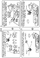
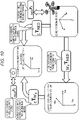
- Fig. 1 is a diagram for describing the processing executed by the information processing apparatus or the information processing system of the present disclosure.
- Fig. 1 illustrates the following four processes.
- Many drones such as a drone 20 illustrated in Fig. 1(1) , perform position control using communication information of a GPS satellite.
- the position information obtained from the GPS satellite is latitude information, longitude information, and height information.
- Many drones often confirm positions and control flight routes using a NED coordinate system in order to fly using these pieces of information.
- the NED coordinate is a coordinate set with north, east, and down as three axes.
- the camera coordinate system and the NED coordinate are completely different coordinate systems. Therefore, for example, a position of each subject included in the captured image of the camera can be indicated using the camera coordinate system, but it is not known which position in the NED coordinate system the subject position indicated by the camera coordinate system corresponds to.
- SLAM coordinate system which is applied to an SLAM process executed by the user terminal 10, that is, the simultaneous localization and mapping (SLAM) process of executing camera position identification (localization) and environment map creation (mapping) in parallel, is used as the world coordinate system which is the reference coordinate system.
- Process 2 Process of capturing image of planned landing position by user terminal, generating “virtual drone camera image” based on captured image, and transmitting generated “virtual drone camera image", GPS position information of planned landing position, and the like to drone or drone management server
- the user 1 uses the user terminal 10 to capture an image of a predetermined position (planned landing position) on the ground where it is desired to land the drone 20, generates a "virtual drone camera image” on the basis of the captured image, and transmits the generated “virtual drone camera image", GPS position information of the planned landing position, and the like to the drone or the drone management server.
- the "virtual drone camera image” is a virtual image estimated to be captured in a case where the planned landing position is captured by a drone camera 22 of the drone 20 in midair.
- the user 1 captures the image of the planned landing position using the user terminal 10, and generates the "virtual drone camera image" on the basis of the captured image.
- This (Process 3) is a process in which the drone 20 reaches midair above the planned landing position on the basis of the GPS position information of the planned landing position received from the user terminal 10 in the above-described (Process 2).
- the drone 20 communicates with a GPS satellite 30, and flies to a position where a self-position coincides with the GPS position information of the planned landing position received from the user terminal 10 while confirming the self-position. With this process, the drone 20 reaches the midair above the planned landing position. (Process 4) Process in which drone confirms planned landing position by image collation between drone camera-captured image and "virtual drone camera image" received from user terminal and performs landing
- This is a process in which the drone 20 confirms the planned landing position by image comparison between a camera-captured image of the camera (drone camera 22) mounted on the drone 20 and the "virtual drone camera image" received from the user terminal and performs landing.
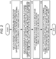
- a flow illustrated in Fig. 2 is a diagram illustrating a flowchart for sequentially executing the respective processes of (Process 1) to (Process 4) illustrated in Fig. 1 .
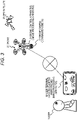
- Fig. 3 is a diagram illustrating one configuration example of the information processing apparatus and an information processing system of the present disclosure.
- An example of the information processing apparatus of the present disclosure is the user terminal 10 such as a camera-equipped smart phone owned by the user 1.
- a drone control apparatus 21 mounted on the drone 20 is also an example of the information processing apparatus of the present disclosure.
- the drone control apparatus 21 includes the drone camera (downward camera) 22.
- the drone control apparatus 21 has a configuration to input a captured image of the drone camera (downward camera) 22 configured separately from the drone control apparatus 21.
- the user terminal 10 and the drone control apparatus 21 have communication functions and can communicate with each other.
- the information processing system of the present disclosure includes, for example, the user terminal 10 and the drone control apparatus 21 illustrated in Fig. 3 .
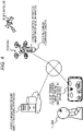
- Fig. 4 illustrates another configuration example of the information processing system of the present disclosure.
- the information processing system of the present disclosure illustrated in Fig. 4 has a configuration in which a drone management server 40 is added to the user terminal 10 such as a camera-equipped smart phone owned by the user 1 and the drone control apparatus 21 mounted on the drone 20.
- the drone management server 40 is also an example of the information processing apparatus of the present disclosure.
- the drone management server 40 communicates with the drone control apparatus 21 of the drone 20 and further communicates with the user terminal 10.
- communication via the drone management server 40 can be performed even in a configuration in which it is difficult to perform direct communication between the user terminal 10 and the drone control apparatus 21.
- the information processing apparatus and the information processing system of the present disclosure have, for example, the configurations illustrated in Figs. 3 and 4 .
- Fig. 5 is a block diagram illustrating a configuration of a user terminal that executes the above-described (Process 1) and (Process 2) .
- the user terminal 10 includes a camera 101, an input unit 102, a (Process 1) execution unit 110, a (Process 2) execution unit 120, and a communication unit 130.
- the (Process 1) execution unit 110 receives an input of a captured image of the drone obtained by the camera 101 capturing the drone in midair, and executes the above-described (Process 1), that is, the following (Process 1). (Process 1) Coordinate analysis process of analyzing relationship between positions on different coordinates used by drone and user terminal to calculate coordinate transformation matrix
- the (Process 1) execution unit 110 includes an image analysis unit 111, a simultaneous localization and mapping unit (slam) 112, and a coordinate transformation matrix generation unit 113.
- the (Process 1) execution unit 110 performs the process by receiving the input of the captured image of the drone obtained as the user 1 captures the drone in midair with the camera 101.
- the image analysis unit 111 receives the input of the captured image of the drone from the camera 101, detects a position (position (pixel position) in the image) of the drone reflected in the captured image of the drone, and outputs detection information to the coordinate transformation matrix generation unit.
- drone position information is position information conforming to the camera coordinate system.
- the simultaneous localization and mapping unit (SLAM) 112 receives the input of the captured image of the drone and performs an SLAM process, that is, the simultaneous localization and mapping (SLAM) process of executing camera position identification (localization) and environment map creation (mapping) in parallel, and outputs self-position and attitude information, calculated by executing a self-position and attitude information calculation of the user terminal 10, to the coordinate transformation matrix generation unit 113.
- SLAM simultaneous localization and mapping
- the coordinate transformation matrix generation unit 113 receives inputs of the information on the position (position (pixel position) in the image) of the drone in the captured image of the drone from the image analysis unit 111 and the self-position and attitude information of the user terminal 10 from the simultaneous localization and mapping unit (SLAM) 112.
- SLAM simultaneous localization and mapping unit
- the coordinate transformation matrix generation unit 113 receives an input of drone position and attitude information from the drone 20 or the drone management server 40.
- drone position and attitude information input from the drone 20 or the drone management server 40 is position information conforming to the coordinate system (NED coordinate system) used for position control of the drone.
- the coordinate transformation matrix generation unit 113 analyzes a corresponding positional relationship between coordinates on different coordinate systems, that is, the camera coordinate system and the NED coordinate system, on the basis of these pieces of input information, and calculates a coordinate transformation matrix that can transform a position of one coordinate system to a position of the other coordinate system.
- SLAM coordinate system which is applied to an SLAM process executed by the user terminal 10, that is, the simultaneous localization and mapping (SLAM) process of executing camera position identification (localization) and environment map creation (mapping) in parallel, is used as the world coordinate system which is the reference coordinate system.
- the coordinate transformation matrix calculated by the (Process 1) execution unit 110 is input to a virtual drone camera generation unit 122 of the (Process 2) execution unit 120.
- the virtual drone camera generation unit 122 uses the coordinate transformation matrix calculated by the (Process 1) execution unit 110 to generate a "virtual drone camera image".
- the "virtual drone camera image” is the virtual image estimated to be captured in the case where the planned landing position is captured by the drone camera 22 of the drone 20 in midair as described above.
- the (Process 2) execution unit 120 includes a transmission data generation unit 121.
- the transmission data generation unit 121 includes the virtual drone camera image generation unit 122.
- the (Process 2) execution unit 120 receives an input of the image capturing the planned landing position and executes the process. As illustrated in Fig. 1(2) , the user 1 uses the user terminal 10 to input the image obtained by capturing the planned landing position on the ground where it is desired to land the drone 20, and performs the process.
- the virtual drone camera image generation unit 122 of the (Process 2) execution unit 120 generates the "virtual drone camera image" which is the virtual image estimated to be captured in the case where the planned landing position is captured by the drone camera 22 of the drone 20 in midair.
- the virtual drone camera image generation unit 122 executes image transformation of the image capturing the planned landing position, for example, projective transformation to generate the "virtual drone camera image”.
- the coordinate transformation matrix calculated by the (Process 1) execution unit 110 is used for this generation process of the "virtual drone camera image”.
- data necessary for the generation process of the "virtual drone camera image" is acquired from the input unit 102, an external drone 200, or the drone management server 40.
- data necessary for the generation process of the "virtual drone camera image” is acquired from the input unit 102, an external drone 200, or the drone management server 40.
- the virtual drone camera image generation unit 122 inputs or acquires these pieces of data and executes the generation process of the "virtual drone camera image”.
- the "virtual drone camera image" generated by the virtual drone camera image generation unit 122 is transmitted together with other information from the transmission data generation unit 121 to the drone 20 or the drone management server 40 via the communication unit 130.
- the drone 20 executes the respective processes of (Process 3) and (Process 4) described with reference to Fig. 1 using these pieces of information. That is, the process of performing landing at the planned landing position designated by the user 1 is executed.
- many drones such as the drone 20 illustrated in Fig. 6 , perform the position control using the communication information of the GPS satellite.
- the position information obtained from the GPS satellite is latitude information, longitude information, and height information.
- Many drones often confirm positions and control flight routes using a NED coordinate system in order to fly using these pieces of information.
- the NED coordinate is a coordinate set with north, east, and down as three axes.
- the camera coordinate system and the NED coordinate are completely different coordinate systems. Therefore, for example, a position of each subject included in the captured image of the camera can be indicated using the camera coordinate system, but it is not known which position in the NED coordinate system the subject position indicated by the camera coordinate system corresponds to.
- the coordinate analysis process of analyzing the relationship between positions on the different coordinates used by the drone and the user terminal to calculate a coordinate transformation matrix is executed. Specifically, the coordinate transformation matrix capable of transforming positions on the different coordinate systems of the NED coordinate system used by the drone and the camera coordinate system used by the user terminal is calculated.
- one fixed world coordinate system is used as one reference coordinate for the transformation process.
- the coordinate system which is applied to the SLAM process executed by the user terminal 10, that is, the simultaneous localization and mapping (SLAM) process of executing camera position identification (localization) and environment map creation (mapping) in parallel, is used as the world coordinate system which is the reference coordinate system.
- the user 1 uses the user terminal 10, which is the camera-equipped smart phone (smartphone), to capture an image of the drone 20 flying in midair as illustrated in Fig. 6 .
- the user terminal 10 is the camera-equipped smart phone (smartphone)
- the user terminal 10 analyzes the captured image and performs the process of analyzing the correspondence relationship between the NED coordinate system, which is the coordinate system used by the drone, and the camera coordinate system used by the user terminal.
- the camera coordinate system changes depending on the movement of the camera, and thus, the world coordinate system (SLAM coordinate system) fixed as the reference coordinate, which serves as one reference, is used in (Process 1).
- SLAM coordinate system fixed as the reference coordinate, which serves as one reference
- the coordinate transformation matrix that can indicate positions on the different coordinate systems of the NED coordinate system used by the drone and the camera coordinate system used by the user terminal as positions on the one reference coordinate is calculated.
- position information in the NED coordinate system (N, E, D) is used for flight control of the drone 20 while a camera-captured image displayed on the user terminal 10 such as the smart phone is image data conforming to the camera coordinate system (Xc, Yc, Zc) set according to an imaging direction of the camera.
- Fig. 8 illustrates the following three coordinate systems.
- the drones 20 perform position control using communication information of a GPS satellite.
- the position information obtained from the GPS satellite is latitude information, longitude information, and height information, and many drones use the NED coordinate system in order to fly using these pieces of information.
- the NED coordinate system is a coordinate set with north, east, and down as three axes.
- the drone 20 or the drone management server 40 of a control center and the like holds flight path information, which is information regarding a flight path or a planned flight path of the drone 20 as path information (N, E, D) in the NED coordinate system, and this path information conforming to the NED coordinate is provided to the user terminal 10 such as the smart phone.
- flight path information is information regarding a flight path or a planned flight path of the drone 20 as path information (N, E, D) in the NED coordinate system, and this path information conforming to the NED coordinate is provided to the user terminal 10 such as the smart phone.
- the world coordinate system (SLAM coordinate system) (reference coordinate system) is mainly used as a coordinate system that defines the entire space used in three-dimensional graphics.
- the world coordinate system is the coordinate system (SLAM coordinate system) which is applied to the SLAM process executed by the user terminal 10, that is, the simultaneous localization and mapping (SLAM) process of executing camera position identification (localization) and environment map creation (mapping) in parallel.
- SLAM coordinate system the coordinate system
- SLAM simultaneous localization and mapping
- the world coordinate system (SLAM coordinate system) is used as the "reference coordinate system”.
- the coordinate transformation matrix configured to enable a position on the camera coordinate system used by the user terminal 10 and a position on the NED coordinate system used by the drone 20 to be indicated as positions on the world coordinate system (SLAM coordinate system), which is one reference coordinate system, is calculated.
- SLAM coordinate system world coordinate system
- each pixel position (u, v) of a display image corresponds to an XYZ-coordinate (Xc, Yc, Zc) in the camera coordinate system.
- a position and an attitude of the camera in the NED coordinate system are estimated from a position of the flight path indicated by the NED coordinate system and each pixel position (u, v) in the display image and the transformation into a position indicated by the camera coordinate system can be performed from the estimated information, it is possible to perform a process of accurately outputting the flight path of the drone 20 on the display image indicated by the camera coordinate system.
- Fig. 9 is a diagram for describing an example of a process of transforming position information of a coordinate system into position information of a different coordinate system.
- Fig. 9 illustrates a coordinate transformation matrix C T Ws which is necessary to transform position information (Xw, Yw, Zw) in the world coordinate system into position information (Xc, Yc, Zc) in the camera coordinate system.
- a position in the world coordinate system (SLAM coordinate system) and a position in the camera coordinate system for one point (X) in a three-dimensional space illustrated in the upper part of the center of Fig. 9 are expressed as follows.
- a coordinate transformation matrix that transforms a position ( Ws P X ) in the world coordinate system (SLAM coordinate system) one point (x) in the three-dimensional space into a position (cPx) in the camera coordinate system is expressed as follows.
- a formula that transforms a position ( Ws P X ) in the world coordinate system (SLAM coordinate system) of one point (x) in the three-dimensional space into a position (cPx) in the camera coordinate system can be expressed by the following (Formula 1).
- C P X T Ws C ⁇ P X Ws
- the camera position corresponds to a position of the camera of the user terminal 10 in the present example.
- the coordinate transformation matrix C T Ws indicated in the above-described is the coordinate transformation matrix that transforms a position ( Ws P X ) in the world coordinate system (SLAM coordinate system) into a position (cPx) in the camera coordinate system.
- SLAM coordinate system world coordinate system
- cPx position in the camera coordinate system
- Fig. 10 illustrates examples of coordinate transformation matrices of these three coordinate systems.
- Fig. 10 illustrates the following three coordinate transformation matrices.
- the coordinate transformation matrix of each of the three coordinate transformation matrices can be calculated from the other two coordinate transformation matrices.
- the coordinate transformation matrix of Ws T NED that transforms a position ( NED P X ) in the NED coordinate system into a position ( Ws P X ) in the world coordinate system (SLAM coordinate system) can be calculated according to the following formula using the other two coordinate transformation matrices ( C T Ws and C T NED ).
- C T Ws -1 is an inverse matrix of C T Ws , and is a matrix that can be calculated from C T Ws .
- C T Ws C T NED ⁇ Ws T NED ⁇ 1
- the coordinate transformation matrix C T NED that transforms a position (NEDPX) in the NED coordinate system into a position (cPx) in the camera coordinate system can be calculated according to the following formula using the other two coordinate transformation matrices ( Ws T NED and C T Ws ).
- C T NED C T Ws ⁇ Ws T NED
- inverse matrices of the three coordinate transformation matrices illustrated in Fig. 10 are coordinate transformation matrices that perform coordinate transformation in opposite directions. That is,
- an inverse matrix A -1 of a coordinate transformation matrix A can be calculated from the coordinate transformation matrix A.
- the "virtual drone camera image” is a virtual image estimated to be captured in a case where the planned landing position is captured by a drone camera 22 of the drone 20 in midair.
- the user 1 captures the image of the planned landing position using the user terminal 10, and generates the "virtual drone camera image" on the basis of the captured image.
- the coordinate transformation matrix ( C T Ws ) that transforms a position ( Ws P X ) in the world coordinate system (SLAM coordinate system) into a position (cPx) in the camera coordinate system among the three coordinate transformation matrices illustrated in Fig. 10 is
- the coordinate transformation matrix ( C T NED ) illustrated in Fig. 10 that is, the coordinate transformation matrix that transforms a position (NEDPX) in the NED coordinate system into a position ( C P X ) in the camera coordinate system is
- a user captures images of the drone 20 flying in midair for a predetermined time using the user terminal 10.
- the drone 20 is not necessarily a drone carrying a package to be delivered to the user.
- the drone 20 needs to be a drone that can acquire position information (position information on the NED coordinates) of a flight path of the drone.
- the drone 20 is flying from right to left according to a lapse of time of times (t1), (t2), and (t3).
- a data processing unit of the user terminal 10 records captured image positions of the drone at least at three different positions in a memory.
- drone imaging positions 52-1 to 52-3 which corresponds to the drones at three different positions on a camera imaging surface 51, such as a C-MOS, are recorded in the memory.
- the drone imaging position corresponds to a display image position displayed on the display unit, and here, a processing example using coordinate positions (u1, v1) to (u3, v3) on a display image is illustrated.
- the coordinate transformation matrix of C T NED can be calculated by using these three different drone positions and information on the three drone imaging positions corresponding to these three drone positions.
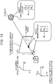
- a pinhole camera model which is a relationship formula defining a relationship between a three-dimensional position M of an object in a case where the object in a three-dimensional space is captured by a general camera (pinhole camera) and an imaging position (imaging pixel position) m of the object on the camera imaging surface, will be described with reference to Figs. 13 and 14 .
- an object image 62 is captured on a camera imaging surface (C-MOS or the like) 51 of the camera.
- the above-described (Formula 3) is a formula indicating a correspondence relationship between a pixel position of a point (m) of the object image 62, included in the camera-captured image, in a camera-captured image plane, that is, a position expressed by the camera coordinate system, and the three-dimensional position (M) of the object 61 in the world coordinate system. Note that ( ⁇ ) above m will be omitted in the following description. In (Formula 3), m represents a coordinate position expressed by a homogeneous coordinate system.
- the position (pixel position) of the point (m) in the object image 62 included in the camera-captured image is expressed by the camera image plane coordinate system.
- the camera coordinate system is a coordinate system in which a focal point of the camera is an origin C, an image plane is a two-dimensional plane of Xc and Yc, and an optical-axis direction (depth) is Zc, and the origin C moves as the camera moves.
- the three-dimensional position (M) of the object 61 which is the imaging subject, is indicated by the world coordinate system including three axes of Xw, Yw, and Zw with the origin O that does not move by the movement of the camera.
- a formula indicating a correspondence relationship between positions of the object in these different coordinate systems is defined as the pinhole camera model of the above-described (Formula 3).
- values of (Formula 3) include the following parameters.
- the camera intrinsic parameter A is the following determinant as illustrated in Fig. 14 .
- A ⁇ f ⁇ k u f ⁇ k u ⁇ cot ⁇ u 0 0 ⁇ f ⁇ k v sin ⁇ v 0 0 0 1
- the camera intrinsic parameter A includes the following values.
- the SLAM process is a process of capturing images (a moving image) by the camera, analyzing a trajectory of a feature point included in the plurality of captured images to estimate a three-dimensional position of the feature point and estimating (localizing) (self) position and attitude of the camera, and can create (map) a surrounding map (environmental map) using the three-dimensional position information of the feature point.
- the process of executing the (self) position identification (localization) of the camera and the creation (mapping) of the surrounding map (environmental map) in parallel is called SLAM.
- EKF extended Kalman filter
- the EKF-based SLAM is, for example, a method of continuously capturing images while moving a camera, obtaining a trajectory (tracking information) of a feature point included in the respective images, and simultaneously estimating the amount of movement of the camera and a three-dimensional position of the feature point by a moving stereo method.
- This EKF-based SLAM process uses "status data" including multidimensional normal distribution data as a probability distribution model including pieces of information as follows, for example,
- the "status data” includes multidimensional normal distribution data including a mean vector, which represents a position, attitude, speed and angular speed of the camera and position information on each feature point, and a variance-covariance matrix.
- the variance-covariance matrix is a matrix including [variance] of inherent status values, such as the position, attitude, speed and angular speed of the camera, and the position information on each feature point, and [covariance] which corresponds to correlation information on combinations of different status values from among the respective status values described above.
- Form 3 can also be developed as, for example, a formula indicating a positional relationship between points (M and m):
- a relationship formula in this case that is, the relationship formula indicating the positional relationship between the respective points (M and m):
- Form 4 corresponds to a formula obtained by changing the parameters corresponding to the world coordinate system of (Formula 3) described above, that is, these parameters of
- Form 4 is a formula obtained by changing the above-described parameters to the following parameters of the NED coordinate system.
- the relationship formula illustrated in (Formula 4) is a formula that defines the correspondence relationship between the object position in the NED coordinate system and the object imaging position in the camera image plane coordinate system, which is the object imaging position in the imaging element in the case where the image of the object is captured by the camera.
- the coordinate transformation matrix that transforms a position ( NED P X ) in the NED coordinate system into a position (cPx) in the camera coordinate system is
- each pixel position (u, v) of the display image displayed on the display unit of the user terminal 10 corresponds to an XY-coordinate (Xc, Yc, Zc) in the camera coordinate system.
- Xc, Yc, Zc XY-coordinate
- the position and attitude of the camera in the NED coordinate system can be estimated from the position of the flight path indicated in the NED coordinate system and each pixel position (u, v) in the display image, and the position of the flight path indicated by the NED coordinate system can be transformed into the position in the camera coordinate system from the estimated information, the path can be accurately output onto the display image indicated by the camera coordinate system.
- Fig. 15(1) is a diagram similar to that described above with reference to Figs. 11 and 12 .
- a user captures images of the drone 20 flying in midair for a predetermined time using the user terminal 10.
- the drone 20 is not necessarily a drone carrying a package to be delivered to the user.
- the drone 20 needs to be a drone that can acquire position information (position information on the NED coordinates) of a flight path of the drone.
- the drone 20 is flying from right to left according to a lapse of time of times (t1), (t2), and (t3).
- a data processing unit of the user terminal 10 records captured image positions of the drone at least at three different positions in a memory.
- drone imaging positions 52-1 to 52-3 which corresponds to the drones at three different positions on the camera imaging surface 51, such as a C-MOS, are recorded in the memory.
- Drone positions in the NED coordinate system at the times (t1), (t2), and (t3) are indicated as follows.
- imaging positions in the camera coordinate system at the times (t1), (t2), and (t3) are indicated as follows.
- C R T NED is a transposed matrix of a rotation matrix of C R NED that transforms the NED coordinate system into the camera coordinate system.
- a -1 is an inverse matrix of the camera intrinsic parameter A described above with reference to Fig. 14 .
- the drone position of NED P Drone in the NED coordinate system can be acquired from the drone or the drone management server.
- the inverse matrix A -1 of the camera intrinsic parameter A is known.
- the drone imaging positions at the times (t1) to (t3) of m Dronet1 to m Dronet3 which are coordinate position information of a camera imaging system, can be acquired by analyzing the camera-captured image.
- a coordinate transformation matrix ( C T NED ) that transforms a position ( NED P X ) in the NED coordinate system into a position (cPx) in the camera coordinate system can be calculated by using the values of the calculation parameters.
- the coordinate transformation matrix ( C T NED ) illustrated in Fig. 16(3) that is, the coordinate transformation matrix ( C T NED ) that transforms a position (NEDPX) in the NED coordinate system into a position (cPx) in the camera coordinate system is a matrix obtained by replacing elements of the world coordinate system in matrix elements of the coordinate transformation matrix ( C T NED ) that transforms a position ( NED P X ) in the NED coordinate system into a position (cPx) in the camera coordinate system, described above with reference to Fig. 9 , with elements of the NED coordinate system.
- C T NED C R NED ⁇ C R NED ⁇ NED P C 0 1
- the matrix elements of the coordinate transformation matrix ( C T NED ) illustrated in (Formula 8) described above are constituted by the parameters obtained by solving the simultaneous equations illustrated in (Formula 7) described above.
- the user terminal 10 which is the information processing apparatus of the present disclosure, first acquires the three different drone positions in the NED coordinate system of the times (t1) to (t3) illustrated in Fig. 15(1) or Fig. 16(1) and the drone imaging positions in the camera coordinate system corresponding to these drone positions.
- the coordinate transformation matrix ( C T NED ) that is, the coordinate transformation matrix ( C T NED ) that transforms a position ( NED P X ) in the NED coordinate system into a position (cPx) in the camera coordinate system is generated using the calculated parameters.
- the position indicated in the NED coordinate system for example, the flight position of the drone can be transformed into the position indicated in the camera coordinate system.
- an inverse matrix ( C T NED -1 ) thereof can be calculated from the coordinate transformation matrix ( C T NED ) that transforms a position ( NED P X ) in the NED coordinate system into a position (cPx) in the camera coordinate system.
- the inverse matrix ( C T NED -1 ) serves as a coordinate transformation matrix ( NED T C ) that transforms a position (cPx) in the camera coordinate system into a position ( NED P X ) in the NED coordinate system.
- the coordinate transformation matrix ( C T Ws ) that transforms a position ( Ws P X ) in the world coordinate system (SLAM coordinate system) into a position (cPx) in the camera coordinate system among the three coordinate transformation matrices illustrated in Fig. 10 can be calculated by performing the SLAM process using the camera, that is, the user terminal 10.
- the coordinate transformation matrix ( C T NED ) that transforms a position (NEDPX) in the NED coordinate system into a position (cPx) in the camera coordinate system can be calculated by the above processing.
- the user terminal 10 can generate the "virtual drone camera image" in the next (Process 2).
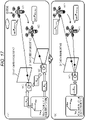
- processing described with reference to Figs. 15 and 16 is processing on the premise that the position and attitude of the camera do not change during an imaging period of the drones at the three different positions, that is, for the drone imaging time of the times (t1) to (t3) illustrated in Fig. 15(1) or Fig. 16(1).
- an imaging surface of the camera that captures the image of the drone at time (t1) is a camera imaging surface 51(t1)
- an imaging surface of the camera that captures the image of the drone at time (t2) is a camera imaging surface 51(t2), and the both have different positions or attitudes.
- a coordinate transformation matrix ( Ctn T Ws ) that transforms the world coordinate system (SLAM coordinate system) into the camera coordinate system at time (tn) is a matrix corresponding to the coordinate transformation matrix ( C T Ws ) that transforms a position ( Ws P X ) in the world coordinate system (SLAM coordinate system) of one point (x) into a position (cPx) in the camera coordinate system, in the three-dimensional space described above with reference to Fig. 9 , in the time (n).
- Matrix elements constituting the coordinate transformation matrix ( Ctn T Ws ) for the transformation into the camera coordinate system at the time (tn) can be acquired in an SLAM process executed by the user terminal 10, that is, a simultaneous localization and mapping (SLAM) process in which camera position identification (localization) and environment map creation (mapping) are executed in parallel.
- SLAM simultaneous localization and mapping
- the coordinate transformation matrices ( Ctn T Ws ) of the time (tn) including the coordinate transformation matrix ( Ct1 T Ws ) that transforms the world coordinate system (SLAM coordinate system) into the camera coordinate system at the time (t1) and the coordinate transformation matrix ( Ct2 T Ws ) that transforms the world coordinate system (SLAM coordinate system) into the camera coordinate system at the time (t2), which are illustrated in Fig. 17 , can be calculated by the SLAM process.
- a coordinate transformation matrix that transforms the camera coordinate system at the time (t1) into the camera coordinate system at the time (t2) is ( Ct2 T Ct1 ), and can be calculated as follows.
- Ct 2 T Ct 1 Ct 2 T Ws ⁇ Ct 1 T Ws ⁇ 1
- the user terminal 10 which is the image processing apparatus of the present disclosure, performs coordinate transformation by applying the above-described coordinate transformation matrix of Ct2 T Ct1 to a drone imaging position on an imaging surface of the camera at the time (t1) at the time of capturing the image of the drone at the time (t1).
- the drone imaging position in the camera coordinate system at the time (t1) is transformed into the drone imaging position in the camera coordinate system at the time (t2) .
- a drone position to be transformed into the imaging surface of the camera at the time (t1) that is,
- drone imaging positions on two different camera coordinate systems can be transformed into drone imaging positions conforming to one common camera coordinate system.
- Fig. 18(1) illustrates an example of a case where positions or attitudes of cameras that capture images of drones at three different positions are different.
- positions or attitudes of the camera (user terminal 10) are different at times (t1), (t2), and (t3), and the cameras having mutually different positions or attitudes capture images of the drone 20 at the times (t1), (t2), and (t3).
- the data processing unit of the user terminal 10 executes the following processing.
- the drone imaging positions in the camera coordinate system at the times (t1) and (t2) are transformed into drone imaging positions in the camera coordinate system at the time (t3).
- a coordinate transformation matrix ( C T NED ) illustrated in Fig. 18(3) that is, the coordinate transformation matrix ( C T NED ) that transforms a position (NEDPX) in the NED coordinate system into a position (cPx) in the camera coordinate system is calculated by using parameters obtained by solving the simultaneous equations.
- an inverse matrix ( C T NED -1 ) that can be calculated on the basis of the coordinate transformation matrix ( C T NED ) serves as a coordinate transformation matrix that transforms a position (cPx) in the camera coordinate system into a position (NEDPX) in the NED coordinate system, which is similar to the processing described above.
- the coordinate transformation matrix that transforms coordinate positions of a position ( NED P X ) in the NED coordinate system and a position ( C P X ) in the camera coordinate system can be calculated even in the case where the position or attitude of the camera changes during the imaging period of the drones at the three different positions.
- Flowcharts illustrated in Fig. 19 and subsequent drawings are diagrams illustrating flowcharts for describing a processing sequence executed by the information processing apparatus of the present disclosure, for example, the user terminal 10 such as a smart phone.
- Processing according to flows illustrated in Fig. 19 and the subsequent drawings can be executed under the control of a control unit (data processing unit), which includes a CPU having a program execution function of the information processing apparatus and the like, according to a program stored in a memory inside the information processing apparatus.
- a control unit data processing unit
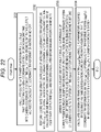
- processing from steps S111 to S114 and processing from steps S121 to S123 illustrated in Fig. 19 can be executed in parallel.
- a process in step S111 is a process of capturing an image of a drone in midair by the user terminal 10.
- the image of the drone 20 in flight is captured using a camera of the user terminal 10 such as the smart phone.
- the image of the drone 20 in flight is captured as described above with reference to Figs. 11 and 12 .
- a user captures images of the drone 20 flying in midair for a predetermined time using the user terminal 10.
- the drone 20 is not necessarily a drone carrying a package to be delivered to the user.
- the drone 20 needs to be a drone that can acquire position information (position information on the NED coordinates) of a flight path of the drone.
- step S112 the user terminal 10 acquires drone imaging position information (imaging position information (m Dronet(n) ) in the camera coordinate system) in the captured image at the time t(n).
- imaging position information m Dronet(n)
- ⁇ ⁇
- This drone imaging position is an imaging position indicated by the camera coordinate system (homogeneous coordinate system) at the time t(n).
- step S113 the user terminal 10 acquires position information (position information ( NED P Dronet(n) ) in the NED coordinate system) of the drone at the time t(n).
- the user terminal 10 which is the information processing apparatus of the present disclosure, can acquire flight path information indicated in the NED coordinate system from the drone 20 or the drone management server 40 of a control center that controls the drone 20 and the like.
- step S114 the user terminal 10 records the imaging position information (imaging position information (m Dronet(n) ) in the camera coordinate system) of the drone at the time t(n) and the position information (position information ( NED P Dronet(n) ) in the NED coordinate system) in the memory in association with the time t(n).
- imaging position information imaging position information (m Dronet(n) ) in the camera coordinate system
- position information position information (NED P Dronet(n) ) in the NED coordinate system) in the memory in association with the time t(n).
- step S121 the user terminal 10 executes the following process.
- An SLAM process is executed at the time t(n), that is, at the drone imaging timing in step S111.
- the SLAM process is the process of executing the camera position identification (localization) and the environmental map creation (mapping) in parallel.
- step S122 the user terminal 10 calculates a coordinate transformation matrix ( Ct(n) T Ws ) that transforms the world coordinate system (SLAM coordinate system) into the camera coordinate system of the imaging time t(n) on the basis of a result of the SLAM process in step S121.
- a coordinate transformation matrix Ct(n) T Ws ) that transforms the world coordinate system (SLAM coordinate system) into the camera coordinate system of the imaging time t(n) on the basis of a result of the SLAM process in step S121.
- step S122 corresponds to the process described above with reference to Fig. 17(1).
- step S123 the user terminal 10 records, in the memory, the coordinate transformation matrix ( Ct(n) T Ws ) calculated in step S122, that is, the coordinate transformation matrix ( Ct(n) T Ws ) that transforms the world coordinate system (SLAM coordinate system) into the camera coordinate system of the imaging time t(n).
- the coordinate transformation matrix ( Ct(n) T Ws ) that transforms the world coordinate system (SLAM coordinate system) into the camera coordinate system of the imaging time t(n).
- step S124 is executed.
- step S124 the user terminal 10 determines whether or not there are three or more entries recorded in the memory.
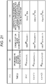
- Fig. 21 illustrates an example in which the pieces of data based on the captured images at the three different drone positions have been recorded.
- entries corresponding to drone imaging times in midair are recorded in the memory.
- the following pieces of data are recorded as data corresponding to the drone imaging time.
- (2) Drone imaging position in camera coordinate system is drone imaging position information (imaging position information (m Dronet(n) ) in the camera coordinate system or the like) in the captured image acquired in step S112 of the flow illustrated in Fig. 19 .
- (3) Drone position in NED coordinate system is position information (position information ( NED P Dronet(n) ) in the NED coordinate system or the like) of the drone in midair at an image capturing timing, the position information being acquired in step S113 of the flow illustrated in Fig. 19 .
- (4) Coordinate transformation matrix that transforms world coordinate system (SLAM coordinate system) into camera coordinate system is a coordinate transformation matrix ( Ct(n) T Ws or the like) that transforms the world coordinate system (SLAM coordinate system) into a camera coordinate system of the imaging time, the coordinate transformation matrix being calculated in step S122 of the flow illustrated in Fig. 19 .
- step S124 of the flowchart illustrated in Fig. 19 it is determined whether or not there are three or more entries recorded in the memory.
- step S124 determines whether the pieces of data based on the captured images at the three different drone positions are not recorded in the memory. If the pieces of data based on the captured images at the three different drone positions are not recorded in the memory, it is determined in step S124 as No, and the processing proceeds to step S125.
- step S125 a time setting parameter n is set to the next time (n+1), and the processing from steps S111 to S114 and the processing from steps S121 to S123 are executed at the next time (n+1).
- step S124 In a case where it is determined in step S124 that the pieces of data based on the captured images at the three different drone positions are recorded in the memory as illustrated in Fig. 21 , the processing proceeds to step S131.
- the user terminal 10 executes the following process in step S131.
- a coordinate transformation matrix ( Ct(out) T Ct(n) or the like) that transforms the camera coordinate system of the drone imaging time into a camera coordinate system of time t(out) at which a drone flight path is output is calculated and recorded in the memory.
- This process corresponds to the process described above with reference to Fig. 17 .
- Data to be recorded in the memory in step S131 is data of (5) Illustrated in Fig. 23 , that is, data of
- time t(n+2) among three entries corresponding to imaging times illustrated in Fig. 23 is assumed as the drone flight path output time t(out).
- a camera coordinate system at the time of capturing an image of the drone coincides with a camera coordinate system at the time of outputting a flight path, and thus, it is unnecessary to additionally record a coordinate transformation matrix.
- step S132 the user terminal 10 executes the following process in step S132.
- a coordinate transformation process is performed by applying a coordinate transformation matrix ( Ctc T Ctn ) to a drone imaging position in a camera coordinate system of a drone imaging time, and the drone imaging position corresponding to a camera coordinate system of the drone flight path output time t(out) is calculated and recorded in the memory.
- a coordinate transformation matrix Ctc T Ctn
- This processing corresponds to the processing described above with reference to Fig. 17 and Fig. 18(1).
- Data to be recorded in the memory in step S132 is data of (6) illustrated in Fig. 23 , that is, data of
- time t(n+2) among the three entries corresponding to imaging times illustrated in Fig. 23 is assumed as the drone flight path output time t(out).
- step S132 the user terminal 10 calculates the following pieces of data and records the calculated data in the memory.
- ⁇ m Dronetn A ⁇ T NED Ctout ⁇ P Dronetn NED
- a coordinate acquired by the above calculation formula is the drone imaging position corresponding to the camera coordinate system of the drone flight path output time t(out). This coordinate position is recorded in the memory.
- ⁇ m Dronetn + 1 A ⁇ T NED Ctout ⁇ P Dronetn + 1 NED
- a coordinate acquired by the above calculation formula is the drone imaging position corresponding to the camera coordinate system of the drone flight path output time t(out). This coordinate position is recorded in the memory.
- a camera coordinate system (C t(n+2) ) of the drone imaging time t(n+2) coincides with the camera coordinate system (C t(out) ) of the drone flight path output time t(out).
- step S133 processes of step S133 and the subsequent steps of the flow illustrated in Fig. 22 will be described.
- step S133 the user terminal 10 executes the following process.
- Form 7 which includes the formulas of the correspondence relationships between each of the drone positions in the NED coordinate system at the three different positions recorded in the memory and each of the drone imaging positions (imaging positions on the camera coordinate system of the time t(out)) corresponding to the respective drone positions, is generated.
- the simultaneous equations to be generated are the simultaneous equations described above with reference to Figs. 15(2), 16(2), and 18(2), and are the simultaneous equations described above as (Formula 7) .
- step S132 that is, the drone imaging position corresponding to the camera coordinate system of the drone flight path output time t(out) is used as the drone imaging position (m Dronetn ) included in the three formulas constituting the simultaneous equations illustrated in (Formula 7).
- step S134 the user terminal 10 calculates a coordinate transformation matrix ( Ct(out) T NED ) including parameters obtained by solving the simultaneous equations (Formula 7) generated in step S133 as matrix elements, that is, the coordinate transformation matrix ( Ct(out) T NED ) (Formula 8) that transforms a position ( NED P X ) in the NED coordinate system into a position ( Ct(out) P X ) in the camera coordinate system.
- a coordinate transformation matrix ( Ct(out) T NED ) including parameters obtained by solving the simultaneous equations (Formula 7) generated in step S133 as matrix elements, that is, the coordinate transformation matrix ( Ct(out) T NED ) (Formula 8) that transforms a position ( NED P X ) in the NED coordinate system into a position ( Ct(out) P X ) in the camera coordinate system.
- This coordinate transformation matrix ( Ct(out) T NED ) corresponds to the coordinate transformation matrix ( C T NED ) described above with reference to Figs. 16(3) and 18(3), and corresponds to the coordinate transformation matrix ( C T NED ) described above as (Formula 8).
- the calculation of the coordinate transformation matrix ( C T NED ), that is, the coordinate transformation matrix ( C T NED ) that transforms a position ( NED P X ) in the NED coordinate system into a position (cPx) in the camera coordinate system is completed.
- step S122 the coordinate transformation matrix ( C T Ws ) that transforms the world coordinate system (SLAM coordinate system) into the camera coordinate system of the imaging time t(n) is calculated in step S122.
- the two coordinate transformation matrices including:
- the user terminal 10 executes the above-described (Process 1), that is, the following (Process 1).
- Processs 1 Coordinate analysis process of analyzing positional relationship on different coordinates used by drone and user terminal to calculate coordinate transformation matrix
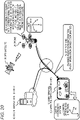
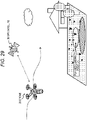
- the user 1 uses the user terminal 10 to capture an image of a position (planned landing position) on the ground where the drone 20 is to be landed as illustrated in Fig. 24 ,.
- the data processing unit of the user terminal 10 generates a "virtual drone camera image" based on the captured image.
- the user terminal 10 transmits the generated "virtual drone camera image", GPS position information of the planned landing position, and the like to the drone or the drone management server.
- the following information is necessary as information necessary for the drone 20 to land at the planned landing position designated by the user 1 illustrated in Fig. 24 , for example, with a high accuracy without any positional deviation.
- the user 1 illustrated in Fig. 24 captures the image of the planned landing position using the user terminal 10 as illustrated in Fig. 24 .
- the data processing unit of the user terminal 10 generates the "virtual drone camera image" on the basis of the captured image.
- the "virtual drone camera image” is a virtual image estimated to be captured in a case where the planned landing position is captured by a drone camera 22 of the drone 20 in midair.
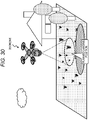
- the user 1 captures the image of the planned landing position using the user terminal 10. Moreover, the user 1 designates an image area of the planned landing position in the captured image as illustrated in Figs. 25(1a) and 25(2a). For example, a process of tapping the image area of the planned landing position with a finger or sliding a finger so as to draw a circle is performed. An application being executed on the user terminal 10 detects the operation of designating the image area performed by the user, and outputs a planned landing position identification mark to a position designated by the user as illustrated in Figs. 25(1b) and 25(2b).
- the data processing unit of the user terminal 10 executes an image transformation process on the basis of the captured image including this planned landing position identification mark to generate the "virtual drone camera image" including the planned landing position identification mark.
- the user terminal 10 analyzes the captured image of the planned landing position and the like, and generates data to be transmitted to the drone 20 or the drone management server 40.
- the user 1 may input, to the user terminal 10, a part of the data necessary for generation of the "virtual drone camera image" and the data to be transmitted to the drone 20 or the drone management server 40.
- the user inputs, for example, the following pieces of data via the input unit of the user terminal 10.
- the user 1 inputs, to the user terminal 10, a height of the user device 10 from a planned landing position at the time of capturing an image of the planned landing position using the user device 10.
- the height at the time of capturing the image for example, it may be configured such that the height of the user is registered in advance in the memory of the user device 10, and the data processing unit of the user device 10 acquires registration information from the memory as the height at the time of capturing the image.
- the user 1 After capturing the image including the planned landing position using the user device 10, the user 1 inputs area designation information indicating which image area of the captured image is an image area of the planned landing position.
- the user 1 displays the captured image on the display unit of the user terminal 10, and taps the image area of the planned landing position within the image with a finger or slides a finger so as to draw a circle.
- the data processing unit of the user terminal 10 detects an area of a screen touched by the user 1 to identify the image area of the planned landing position within the image, acquires pixel position information corresponding to the image area of the planned landing position, and records the acquired pixel position information in the memory of the user terminal 10.
- the user designates a yaw angle (azimuth angle) when the drone 20 descends to the planned landing position.
- the user performs a process of designating the yaw angle (azimuth angle) when the drone 20 descends to the planned landing position, and transmitting such designated information to the drone 20 or the drone management server 40.
- the “virtual drone camera image” is an image generated as the data processing unit of the user terminal 10 transforms the image of the planned landing position captured by the user terminal 10, and is the virtual image in the case where the image of the planned landing position is assumed to be captured using the downward camera mounted on the drone.
- the user can also designate the altitude of the camera that captures the "virtual drone camera image" generated by the data processing unit of the user terminal 10.
- the data processing unit of the user terminal 10 generates the "virtual drone camera image" estimated to be captured at the time of looking down on the planned landing position from the height designated by the user according to the designation by the user.
- height data designated in advance by a delivery service side that grasps specifications of the drone or a drone manufacturer, may be used as the default value.
- the data processing unit of the user terminal 10 executes a transformation process of the image captured by the user 1, that is, the image capturing of the planned landing position to generate the "virtual drone camera image" obtained by capturing the planned landing position from directly above, and further, generates data to be transmitted to the drone 20 or the drone management server 40 using the generated image, data input by the user, and the like.
- the data processing unit of the user terminal 10 transmits the generated data to the drone 20 or the drone management server 40.
- the flowchart illustrated in Fig. 26 is a flowchart illustrating a detailed sequence when the user terminal 10 executes (Process 2), that is, the following (Process 2).
- Process 2 Process of capturing image of planned landing position by user terminal, generating “virtual drone camera image” based on captured image, and transmitting generated “virtual drone camera image", GPS position information of planned landing position, and the like to drone or drone management server.
- step S201 the user 1 captures an image of a planned landing position using the user terminal 10.
- the user 1 captures the image including the planned landing position.
- step S202 the user 1 inputs height information of the user terminal 10 at the time of capturing the image of the planned landing position to the user terminal 10.
- the data processing unit of the user terminal 10 records the input height information in the memory.
- the height at the time of capturing the image for example, it may be configured such that the height of the user is registered in advance in the memory of the user device 10, and the data processing unit of the user device 10 acquires registration information from the memory as the height at the time of capturing the image as described above.
- step S203 the user 1 inputs image area designation information of the planned landing position included in the captured image displayed on the display unit of the user terminal 10.
- the user 1 displays the captured image on the display unit of the user terminal 10, and taps the image area of the planned landing position within the image with a finger or slides a finger so as to draw a circle.
- This process is the process described above with reference to Fig. 25 .
- the user 1 displays the image obtained by capturing the planned landing position on the display unit of the user terminal 10, and designates the image area of the planned landing position in the captured image as illustrated in Figs. 25(1a) and 25(2a). For example, a process of tapping the image area of the planned landing position with a finger or sliding a finger so as to draw a circle is performed.
- the application being executed in the data processing unit of the user terminal 10 detects the area of the screen touched by the user 1 to identify the image area of the planned landing position within the image, detects the operation of designating the image area performed by the user, and outputs the planned landing position identification mark to the position designated by the user as illustrated in Figs. 25(1b) and 25(2b). Moreover, the pixel position information corresponding to the image area of the planned landing position is acquired and recorded in the memory.
- step S204 the data processing unit of the user terminal 10 transforms the captured image and generates the "virtual drone camera image" which is an estimated captured image in a case where the image of the planned landing position is assumed to be captured by the drone camera 22 of the drone 20 in midair.
- the data processing unit of the user terminal 10 executes the image transformation process on the basis of the captured image including this planned landing position identification mark to generate the "virtual drone camera image" including the planned landing position identification mark as described above with reference to Fig. 25 .
- information necessary for the virtual drone camera image generation process for example, information on specifications of the drone camera 22 of the drone 20, for example, parameters such as the attitude, a focal position, and the angle of view of the drone camera 22 may be set by the user, or predetermined values (default values) may be used. Alternatively, values acquired from the drone 20 or the drone management server 40 may be used.
- step S205 the data processing unit of the user terminal 10 transmits the "virtual drone camera image" generated in step S204, GPS position information of the planned landing position, and attribute data corresponding to the generated "virtual drone camera image” to the drone 20 or the drone management server 40.
- the drone 20 uses these pieces of data to execute (Process 3) and (Process 4) described with reference to Fig. 1 .
- the drone 20 first executes the process of moving to midair above the planned landing position on the basis of the GPS position information of the planned landing position received from the user terminal 10 as the process of (Process 3).
- the drone 20 performs the process of collating the "virtual drone camera image" transmitted from the user terminal 10 with the captured image of the drone camera 22, confirms the planned landing position included in the captured image of the drone camera 22, and executes the process of landing toward the planned landing position.
- the drone 20 can land at the planned landing position designated by the user with a high accuracy.
- step S204 the data processing unit of the user terminal 10 transforms the captured image and generates the "virtual drone camera image" which is the estimated captured image in the case where the image of the planned landing position is assumed to be captured by the drone camera.
- the zenith direction is a direction obtained by rotating a Z-axis direction of the NED coordinate system by 180 degrees, that is, a direction opposite to the Z axis.
- the data processing unit of the user terminal 10 calculates the following values (a) to (d).
- a map generation process to which the SLAM process is applied that is, a map generation process of the external environment included in the camera-captured image is described in, for example, Patent Document 2 ( Japanese Patent Application Laid-Open No. 5920352 ), which is a prior application of the present applicant, and this technique can be applied.
- a relationship formula (corresponding pixel positional relationship formula) between a position on the captured image of the user terminal 10 and a position on the "virtual drone camera image", the relationship formula being configured to generate the "virtual drone camera image”, is expressed by the following (Formula 10). Note that the following (Formula 10) is the relationship formula generated on the premise that the camera of the user terminal 10 and the drone camera 22 (downward camera) of the drone 20 conform to the pinhole camera model.
- Form 10 is calculated from transformation information (Formula 8) (Table 1) among the following coordinate systems and the pinhole camera model (Formula 3), and is the relationship formula that enables calculation of a corresponding pixel position [us, vs] on the image captured by the user if a pixel position [u N , v N ] on the "virtual drone camera image" is designated.
- Form 10 is the corresponding pixel positional relationship formula indicating the correspondence relationship between a pixel position on the captured image obtained by capturing the planned landing position by the camera of the user terminal 10 and a pixel position on the "virtual drone camera image" which is the estimated captured image in the case where the image of the planned landing position is assumed to be captured by the virtual drone camera mounted on the drone 20.
- This calculation formula is a calculation formula of a vector connecting a focal position of a virtual drone camera image to a place of a landing plane corresponding to a coordinate position on the virtual drone camera image in a coordinate system expressed by a position and an attitude of the landing plane.
- This calculation formula is a calculation formula of a vector that connects a position of the user terminal to a place of a landing plane corresponding to a coordinate position on the captured image of the user terminal in the coordinate system expressed by the position and attitude of the landing plane.
- This calculation formula is a calculation formula of a vector connecting the focal position of the virtual drone camera image to the planned landing position in the coordinate system expressed by the position and attitude of the landing plane.
- This calculation formula is a calculation formula of a vector obtained by subtracting the planned landing position from a position of the user terminal in the coordinate system expressed by the position and attitude of the landing plane.
- all the parameters in (Formula 10) are any of (Process 1) and (Process 2) executed by the user terminal 10, data acquired from the drone 20 or the drone management server 40, data stored in the user terminal 10, or data input to the user terminal 10 by the user, and the corresponding pixel positional relationship formula illustrated in (Formula 10) described above can be generated using these pieces of data.
- parameters used in the corresponding pixel positional relationship formula are parameters calculated using the a coordinate transformation matrix, which is applied to the transformation among the three coordinate systems calculated in (Process 1), that is, the three coordinate systems of:
- an attitude ( N R NED ) and a focal position ( NED P N ) of the "virtual drone camera image" in the NED coordinate system illustrated in the above table and Figs. 27 and 28 are an attitude (attitude ( N R NED ) in the NED coordinate system) of the drone camera 22 estimated to capture the same image as the "virtual drone camera image” and a focal position (focal position ( NED P N ) in the NED coordinate system) of the drone camera 22 estimated to capture the same image as the "virtual drone camera image”.
- These parameters can be determined by the user who operates the user terminal 10. Alternatively, a preset default value may be used in a case where the "virtual drone camera image" generation process is executed in the user terminal 10.
- these parameters are transmitted from the user terminal 10 to the drone 20 or the drone management server 40 together with the "virtual drone camera image" generated by the user terminal 10.
- the user terminal 10 generates the "virtual drone camera image" using the relationship formula illustrated in the above-described (Formula 10), that is, the relationship formula (corresponding pixel positional relationship formula) between the position on the captured image of the user terminal 10 and the position on the "virtual drone camera image".
- the user terminal 10 executes the "virtual drone camera image” generation process using the relationship formula (corresponding pixel positional relationship formula) illustrated in the above-described (Formula 10) according to the following processing procedure.
- the user terminal 10 calculates a pixel position (in the homogeneous coordinate system) [u S , v S , 1] on the captured image of the user terminal 10 which corresponds to a pixel position (in the homogeneous coordinate system) [u N , V N , 1] on the "virtual drone camera image" by using (Formula 10) described above.
- an output value (color) of a pixel position [us, vs] on the captured image of the user terminal 10 is set as an output value (color) of a pixel position [u N , v N ] on the "virtual drone camera image”.
- This process is executed for all pixels of the "virtual drone camera image” to generate the "virtual drone camera image”.
- step S204 of the flow illustrated in Fig. 26 the "virtual drone camera image" is generated using the captured image of the user terminal 10 according to the above-described procedure.
- the data processing unit of the user terminal 10 executes the image transformation process on the basis of the captured image including this planned landing position identification mark to generate the "virtual drone camera image" including the planned landing position identification mark as described above with reference to Fig. 25 .
- the user terminal 10 transmits the following pieces of data to the drone 20 or the drone management server 40.
- the user terminal 10 transmits these pieces of data to the drone 20 or the drone management server 40.
- attribute data corresponding to "virtual drone camera image” specifically includes, for example, the following pieces of data.
- predefined values may be used as the parameters of the above-described (2) and (3).
- default values recorded in advance in the memories of both the user terminal 10 and the drone 20 may be used.
- the drone 20 executes (Process 3) and (Process 4) described with reference to Fig. 1 using the pieces of data of the above-described (3a) to (3c).
- the drone control apparatus 21 of the drone 20 receives transmission data of the user terminal 10, that is, the following data directly from the user terminal 10 or via the drone management server 40.
- the drone control apparatus 21 of the drone 20 executes the processes of (Process 3) and (Process 4) illustrated in Fig. 1 using the transmission data of the user terminal 10.
- the drone control apparatus 21 of the drone 20 controls the drone 20 according to the GPS position information of the planned landing position transmitted from the user terminal 10, and reaches midair above the planned landing position.
- the drone control apparatus 21 of the drone 20 performs the process of collating the "virtual drone camera image" transmitted from the user terminal 10 with the captured image of the drone camera 22, confirms the planned landing position included in the captured image of the drone camera 22, and executes the landing process toward the planned landing position in (Process 4).
- the data processing unit of the drone control apparatus 21 of the drone 20 executes processing using the following pieces of data transmitted from the user terminal 10 in the process of confirming the planned landing position by the image collation in (Process 4) described above. That is,
- the data processing unit of the drone control apparatus 21 of the drone 20 uses these pieces of data to confirm the planned landing position included in the captured image of the drone camera 22.
- the drone 20 starts to descend toward the planned landing position, and an image captured by the drone camera 22 at a position and an attitude indicated by the parameters of the above-described (3b) and (3c), that is, these parameters of:
- the data processing unit of the drone control apparatus 21 of the drone 20 uses the parameter of the above-described (3a), that is, the following parameter of
- the drone control apparatus 21 of the drone 20 lands the drone 20 toward the identified planned landing position.
- the drone control apparatus 21 of the drone 20 can land the drone 20 at the planned landing position designated by the user 1 with a high accuracy.
- the image of the planned landing position is captured by the user terminal 10, and the "virtual drone camera image” is generated using the captured image obtained by the user terminal 10 using the relationship formula (corresponding pixel positional relationship formula) illustrated in (Formula 10) described above in (Process 2) illustrated in Fig. 1 .
- the process of calculating the coordinate transformation matrix ( Ws T NED ) executed in (Process 1) requires the process in which the user 1 captures the moving image of the drone in midair using the user terminal 10 as described above with reference to Figs. 11 and 12 , for example, and there is a problem that the burden on the user and a processing load of the user terminal 10 increase.
- the drone management server 40 or the drone 20 capable of communicating with the user terminal 10 holds the coordinate transformation matrix ( Ws T NED ) calculated in advance, and the held data is provided from the drone management server 40 or the drone 20 to the user terminal 10.
- it may be configured such that an image captured by the user terminal 10, for example, the moving image of the drone in midair described above with reference to Figs. 11 and 12 is captured, the captured image is transmitted to the drone management server 40 or the drone 20, and the drone management server 40 or the information processing apparatus on the drone 20 side calculates the coordinate transformation matrix ( Ws T NED ) and transmit the calculated coordinate transformation matrix to the user terminal 10.
- an image captured by the user terminal 10 for example, the moving image of the drone in midair described above with reference to Figs. 11 and 12 is captured
- the captured image is transmitted to the drone management server 40 or the drone 20
- the drone management server 40 or the information processing apparatus on the drone 20 side calculates the coordinate transformation matrix ( Ws T NED ) and transmit the calculated coordinate transformation matrix to the user terminal 10.
- the drone management server 40 or the information processing apparatus on the drone 20 side holds a "database (DB) in which an image and a NED coordinate system are associated", a DB-registered image having high similarity with a captured image of the drone received from the user terminal 10 is retrieved using the database, and the NED coordinate system recorded in the DB in association with the retrieved DB-registered image is selected.
- DB database
- the "DB (database) in which an image and an NED coordinate system are associated” is, for example, a database in which an image obtained by capturing the drone in midair from the ground and position and attitude (camera position and attitude in the NED coordinate system) information in the NED coordinate system associated with the image are registered.
- This database is generated in advance. That is, images obtained by capturing the drone in midair using cameras having various different positions and attitudes are generated, and the database (DB) in which positions and attitudes in the NED coordinate system (camera positions and attitudes in the NED coordinate system) are associated with these images is constructed.
- DB database in which positions and attitudes in the NED coordinate system (camera positions and attitudes in the NED coordinate system) are associated with these images is constructed.
- a processing configuration of the user terminal 10 in a case where this database is used will be described with reference to Fig. 31 .
- Fig. 31 is a block diagram illustrating a configuration of a user terminal that executes (Process 1) and (Process 2) similarly to the configuration diagram described above with reference to Fig. 5 .
- FIG. 31 A difference between Fig. 31 and Fig. 5 described above is a configuration of the (Process 1) execution unit 110.
- Fig. 31 has a configuration in which the image analysis unit 111 illustrated in Fig. 5 is omitted.
- the (Process 1) execution unit 110 transmits a captured image of a drone input from the camera 101 to an external device such as the drone management server 40 via the communication unit 130.
- the external device such as the drone management server 40 includes the "database (DB) in which an image and a NED coordinate system are associated".
- the external device such as the drone management server 40 executes a process of collating the captured image of the drone received from the user terminal 10 and an image registered in the database, and selects a matching or similar registered image.
- the drone position and attitude information (NED coordinate system) recorded in the database corresponding to the selected registered image is acquired and transmitted to the user terminal 10.
- the coordinate transformation matrix generation unit 113 of the (Process 1) execution unit 110 of the user terminal 10 inputs the drone position and attitude information (NED coordinate system), further analyzes the corresponding positional relationship between coordinates in the camera coordinate system and the NED coordinate system by using self-position and attitude information of the user terminal 10 input from the simultaneous localization and mapping unit (SLAM) 112, and calculates a coordinate transformation matrix that enables transformation of a position of one coordinate system into a position of another coordinate system.
- SLAM simultaneous localization and mapping unit
- an image captured by the user terminal 10 for example, the moving image of the drone in midair described above with reference to Figs. 11 and 12 is captured, and the captured image is transmitted to the drone management server 40 or the drone 20.
- the drone management server 40 or the information processing apparatus on the drone 20 side executes the process of collating the image received from the user terminal 10 and the registered image of the "DB in which an image and an NED coordinate system are associated".
- the drone management server 40 or the information processing apparatus on the drone 20 side selects a DB-registered image matching or similar to the image received from the user terminal 10, acquires a position and an attitude camera position and attitude in the NED coordinate system) in the NED coordinate system recorded in association with the selected DB-registered image, and transmits the acquired camera position and attitude in the NED coordinate system to the user terminal 10 on the user side.
- Ws T NED a coordinate transformation matrix
- the processing may be shared among a plurality of devices.
- DB database in which an image and an NED coordinate system are associated
- the user 1 executes the process of capturing the image of the predetermined position (planned landing position) on the ground where it is desired to land the drone 20 using the user terminal 10 and generating the "virtual drone camera image" on the basis of the captured image in (Process 2),
- the "virtual drone camera image” is a virtual image estimated to be captured in a case where the planned landing position is captured by a drone camera 22 of the drone 20 in midair.
- the "virtual drone camera image" generation process is also performed by the drone management server 40 or the information processing apparatus on the drone 20 side instead of the user terminal 10.
- the user 1 uses the user terminal 10 to capture the image of the predetermined position (planned landing position) on the ground where it is desired to land the drone 20, and transmits the captured image to the drone management server 40 or the drone 20.
- the drone management server 40 or the information processing apparatus of the drone 20 analyzes the captured image of the planned landing position received from the user terminal 10, and executes processing similar to (Process 2) described above to generate the "virtual drone camera image", that is, the virtual image estimated to be captured in a case where the planned landing position is captured by the drone camera 22 of the drone 20 in midair.
- the user 1 only needs to capture an image required in (Process 1) and (Process 2) using the user terminal 10 and transmit the captured image to the drone management server 40 or the drone 20.
- Fig. 32 is a diagram illustrating a configuration example of a user terminal 100 which is the information processing apparatus of the present disclosure and a drone control apparatus 200 mounted on the drone 20.
- the user terminal 100 is, for example, a camera-equipped communication terminal such as a smart phone.
- a device such as a PC or a camera device may be used without being limited to the smart phone.
- the user terminal 100 has a configuration capable of communicating with the drone control apparatus 200 and a drone management server 300.
- the drone control apparatus 200 causes the drone 20 to fly according to a predefined flight path using, for example, communication information with the drone management server 300 or communication information with a GPS satellite.
- the user terminal 100 includes a camera 151, a data processing unit 152, a storage unit (memory) 153, a communication unit 154, a display unit 155, an input unit 156, and an output unit 157.
- the camera 151 is used, for example, for the process of capturing an image of the drone or image capturing in the SLAM process.
- the data processing unit 152 executes the above-described processes, specifically, the processes such as (Process 1) and (Process 2) described above with reference to Fig. 1 . That is, the following processes are executed.
- the data processing unit 152 controls processing to be executed in the user terminal 100, such as the SLAM process and image capturing control required in (Process 1) and (Process 2) described above.
- the data processing unit 152 includes, for example, a processor such as a CPU having a program execution function, and executes processing according to a program stored in the storage unit 153.
- the storage unit (memory) 153 is used as a storage area and a work area of the program executed by the data processing unit 152.
- the storage unit (memory) 153 is also used as a storage area of various parameters to be applied to the processing.
- the storage unit (memory) 153 includes a RAM, a ROM, and the like.
- the communication unit 154 executes communication with the drone control apparatus 200 and the drone management server 300. For example, a process of receiving flight path information or the like corresponding to a GPS position of the drone 20 from the drone control apparatus 200 or the drone management server 300 is performed.
- the display unit 155 displays a camera-captured image, for example, displays a captured image of the drone, a captured image of the planned landing position, and the like.
- the input unit 156 is a unit operated by the user, and is used for various processes, for example, a process of inputting a user request such as start and end of data processing such as image capturing and the SLAM process.
- the output unit 157 includes a sound output unit, an image output unit, and the like.
- the drone control apparatus 200 includes a data processing unit 201, a flight control unit 202, a camera 203, a communication unit 204, and a positioning sensor (GPS information reception and analysis unit) 205.
- the data processing unit 201 plans and determines a flight path of the drone 20.
- a specific flight path is planned and determined on the basis of flight path instruction information received from the drone management server 300, the GPS position information of the planned landing position received from the user terminal 100, the "virtual drone camera image", and the like.
- the flight control unit 202 executes flight control, landing control, and the like to make the drone control apparatus 200 to fly according to the flight path determined by the data processing unit 201.
- the camera 203 captures, for example, an image of the planned landing position.
- the captured image is input to the data processing unit 201, and the data processing unit 201 performs a collation process with the "virtual drone camera image" received from the user terminal 100.
- the data processing unit 201 confirms the planned landing position included in the captured image of the camera 203 on the basis of the collation process, and outputs a control command for executing a landing process toward the planned landing position to the flight control unit 202.
- the flight control unit 202 executes the landing process according to the control command.
- the communication unit 204 executes communication with the drone management server 300 and the user terminal 100.
- the positioning sensor (GPS information reception and analysis unit) 205 executes communication with a GPS satellite 400, analyzes a current position (latitude, longitude, and height) of the drone control apparatus 200 on the basis of the communication information with the GPS satellite 400, and outputs the analyzed information to the flight control unit 202.
- the flight control unit 202 uses information input from the positioning sensor (GPS information reception and analysis unit) 205 to perform flight toward a target position or landing at the planned landing position.
- GPS information reception and analysis unit GPS information reception and analysis unit
- the similar processing can be performed by replacing the drone in the above-described embodiment with a flying vehicle.
- a central processing unit (CPU) 501 functions as a data processing unit that executes various processes according to a program stored in a read only memory (ROM) 502 or a storage unit 508. For example, the processing according to the sequence described in the above-described embodiments is performed.
- the program to be executed by the CPU 501, data, and the like are stored in a random access memory (RAM) 503.
- the CPU 501, the ROM 502, and the RAM 503 are mutually connected via a bus 504.
- the CPU 501 is connected to an input/output interface 505 via the bus 504, and an input unit 506 including various sensors, a camera, a switch, a keyboard, a mouse, a microphone, and an output unit 507 including a display and a speaker are connected to the input/output interface 505.
- an input unit 506 including various sensors, a camera, a switch, a keyboard, a mouse, a microphone, and an output unit 507 including a display and a speaker are connected to the input/output interface 505.
- the storage unit 508 connected to the input/output interface 505 is configured using, for example, a USB memory, an SD card, a hard disk, and the like and stores a program to be executed by the CPU 501 and various types of data.
- the communication unit 509 functions as a transmission/reception unit of data communication via a network such as the Internet or a local area network, and communicates with an external device.
- a drive 510 connected to the input/output interface 505 drives a removable medium 511 such as a magnetic disk, an optical disk, a magneto-optical disk, and a semiconductor memory such as a memory card, and executes data recording or reading.
- a removable medium 511 such as a magnetic disk, an optical disk, a magneto-optical disk, and a semiconductor memory such as a memory card
- the series of processing described in the specification can be executed by hardware, software, or a complex configuration of the both.
- the processing is executed using software
- the program can be recorded in a recording medium in advance.
- LAN local area network
- system refers to a logical set configuration of a plurality of apparatuses, and is not limited to a system in which apparatuses of the respective configurations are provided in the same housing.
- the configuration capable of accurately landing the drone at the planned landing position designated by the user is achieved.
- the user terminal generates the virtual drone camera image, which is the estimated captured image in the case where it is assumed that the virtual drone camera mounted on the drone has captured an image of the planned landing position on the basis of the captured image obtained by capturing the planned landing position of the drone with the user terminal, and transmits the generated virtual drone camera image to the drone.
- the drone collates the virtual drone camera image with the image captured by the drone camera and lands at the planned landing position in the image captured by the drone camera.
- the user terminal generates the corresponding pixel positional relationship formula indicating the correspondence relationship between the pixel position on the captured image of the user terminal and the pixel position on the captured image of the virtual drone camera, and generates the virtual drone camera image using the generated relationship formula.
- the configuration capable of accurately landing the drone at the planned landing position designated by the user is achieved.
Landscapes
- Engineering & Computer Science (AREA)
- Aviation & Aerospace Engineering (AREA)
- Physics & Mathematics (AREA)
- General Physics & Mathematics (AREA)
- Radar, Positioning & Navigation (AREA)
- Remote Sensing (AREA)
- Automation & Control Theory (AREA)
- General Engineering & Computer Science (AREA)
- Computing Systems (AREA)
- Mathematical Physics (AREA)
- Theoretical Computer Science (AREA)
- Control Of Position, Course, Altitude, Or Attitude Of Moving Bodies (AREA)
Applications Claiming Priority (2)
| Application Number | Priority Date | Filing Date | Title |
|---|---|---|---|
| JP2019227024 | 2019-12-17 | ||
| PCT/JP2020/043959 WO2021124826A1 (fr) | 2019-12-17 | 2020-11-26 | Dispositif, système et procédé de traitement d'informations, et programme |
Publications (3)
| Publication Number | Publication Date |
|---|---|
| EP4080314A1 true EP4080314A1 (fr) | 2022-10-26 |
| EP4080314A4 EP4080314A4 (fr) | 2023-01-04 |
| EP4080314B1 EP4080314B1 (fr) | 2024-07-24 |
Family
ID=76477356
Family Applications (1)
| Application Number | Title | Priority Date | Filing Date |
|---|---|---|---|
| EP20903464.4A Active EP4080314B1 (fr) | 2019-12-17 | 2020-11-26 | Dispositif, système et procédé de traitement d'informations, et programme |
Country Status (5)
| Country | Link |
|---|---|
| US (1) | US20230052360A1 (fr) |
| EP (1) | EP4080314B1 (fr) |
| JP (1) | JP7677160B2 (fr) |
| CN (1) | CN114787741B (fr) |
| WO (1) | WO2021124826A1 (fr) |
Families Citing this family (5)
| Publication number | Priority date | Publication date | Assignee | Title |
|---|---|---|---|---|
| JP7626057B2 (ja) * | 2021-12-22 | 2025-02-04 | トヨタ自動車株式会社 | 車両、情報処理システム、プログラム、及び情報処理装置 |
| US12488543B2 (en) * | 2023-03-28 | 2025-12-02 | International Business Machines Corporation | Distributed rendering of digital objects in augmented reality environments |
| TWI882420B (zh) * | 2023-08-29 | 2025-05-01 | 台達電子工業股份有限公司 | 用於橋梁檢測的無人飛行裝置及方法 |
| WO2026004376A1 (fr) * | 2024-06-26 | 2026-01-02 | ソニーグループ株式会社 | Procédé de commande, programme, et système de commande |
| CN120742941B (zh) * | 2025-08-26 | 2025-11-28 | 拓恒技术有限公司 | 基于视觉识别的无人机降偏校正方法 |
Family Cites Families (12)
| Publication number | Priority date | Publication date | Assignee | Title |
|---|---|---|---|---|
| JPS5920352B2 (ja) | 1977-04-19 | 1984-05-12 | 東洋醸造株式会社 | 親規抗生物質アクレアシンDr |
| KR100842104B1 (ko) * | 2007-06-15 | 2008-06-30 | 주식회사 대한항공 | Ads―b와 영상정보를 이용한 무인항공기의 자동 착륙유도 제어 방법 |
| EP2750110B1 (fr) * | 2011-08-24 | 2020-03-18 | Sony Corporation | Dispositif de traitement d'informations, procédé de traitement d'informations et programme |
| IL237130A0 (en) | 2015-02-05 | 2015-11-30 | Ran Krauss | Landing and loading system for an unmanned aircraft |
| CN105599912A (zh) * | 2016-01-27 | 2016-05-25 | 谭圆圆 | 无人飞行器的自动降落方法及自动降落装置 |
| KR20180017674A (ko) * | 2016-08-10 | 2018-02-21 | 엘지전자 주식회사 | 이동 단말기 및 그 제어 방법 |
| US10049589B1 (en) * | 2016-09-08 | 2018-08-14 | Amazon Technologies, Inc. | Obstacle awareness based guidance to clear landing space |
| MX2019007384A (es) * | 2016-12-21 | 2020-02-05 | Walmart Apollo Llc | Sistemas y metodos para entregar productos a traves de vehiculos aereos no tripulados a lugares de entrega designados por los clientes. |
| US10996683B2 (en) * | 2018-02-09 | 2021-05-04 | Skydio, Inc. | Aerial vehicle touchdown detection |
| CN109911231B (zh) * | 2019-03-20 | 2022-07-19 | 武汉理工大学 | 基于gps和图像识别混合导航的无人机自主着舰方法与系统 |
| US10928508B2 (en) * | 2019-04-12 | 2021-02-23 | Ford Global Technologies, Llc | Camera and radar fusion |
| CN110254258B (zh) * | 2019-06-13 | 2021-04-02 | 暨南大学 | 一种无人机无线充电系统及方法 |
-
2020
- 2020-11-26 JP JP2021565419A patent/JP7677160B2/ja active Active
- 2020-11-26 WO PCT/JP2020/043959 patent/WO2021124826A1/fr not_active Ceased
- 2020-11-26 EP EP20903464.4A patent/EP4080314B1/fr active Active
- 2020-11-26 CN CN202080085944.7A patent/CN114787741B/zh active Active
- 2020-11-26 US US17/784,105 patent/US20230052360A1/en active Pending
Also Published As
| Publication number | Publication date |
|---|---|
| JP7677160B2 (ja) | 2025-05-15 |
| US20230052360A1 (en) | 2023-02-16 |
| EP4080314B1 (fr) | 2024-07-24 |
| EP4080314A4 (fr) | 2023-01-04 |
| JPWO2021124826A1 (fr) | 2021-06-24 |
| WO2021124826A1 (fr) | 2021-06-24 |
| CN114787741A (zh) | 2022-07-22 |
| CN114787741B (zh) | 2025-08-01 |
Similar Documents
| Publication | Publication Date | Title |
|---|---|---|
| EP4080314B1 (fr) | Dispositif, système et procédé de traitement d'informations, et programme | |
| EP3208774B1 (fr) | Procédés de localisation au moyen de photos géolocalisées et d'une visualisation tridimensionnelle | |
| Sona et al. | Experimental analysis of different software packages for orientation and digital surface modelling from UAV images | |
| CN112184812B (zh) | 提升无人机相机对AprilTag识别定位精度方法及定位方法和系统 | |
| US20250200800A1 (en) | Information processing device, mobile device, information processing system, and method | |
| EP3447729B1 (fr) | Localisation de véhicule 2d à l'aide de geoarcs | |
| US20040062419A1 (en) | Landmark, apparatus, and method for effectively determining position of autonomous vehicles | |
| Kinnari et al. | GNSS-denied geolocalization of UAVs by visual matching of onboard camera images with orthophotos | |
| CN108427438A (zh) | 飞行环境检测方法、装置、电子设备及存储介质 | |
| Yahyanejad et al. | Incremental mosaicking of images from autonomous, small-scale uavs | |
| JP7237694B2 (ja) | 農業支援システム | |
| US12087172B2 (en) | Image processing device and image processing method | |
| EP3754298A1 (fr) | Support d'installation d'aéronef sans pilote, procédé de mesure, dispositif de mesure, système de mesure et programme | |
| Pagani et al. | Sensors for location-based augmented reality the example of galileo and egnos | |
| JP2018072316A (ja) | ジオアーク(geoarc)を使用したビークルの二次元位置の特定 | |
| JP7682607B2 (ja) | 情報処理装置、制御方法、プログラム及び記憶媒体 | |
| CN116540206A (zh) | 一种足式机器人高程估计方法、装置及系统 | |
| Zhuge et al. | 3-D motion trajectory measurement for the target through a multi-UAVs system | |
| CN110853098A (zh) | 机器人定位方法、装置、设备及存储介质 | |
| EP3943979A1 (fr) | Localisation de dispositif intérieur | |
| Brown et al. | Inertial navigation electro-optical aiding during gps dropouts | |
| Liu et al. | A Coarse-to-Fine Localization Algorithm for UAVs Based on Heterogeneous Image Matching | |
| Chatziparaschis et al. | Real-time unmanned aerial vehicle surveying using spatial criteria: a simulated study | |
| Armenakis et al. | Feasibility study for pose estimation of small UAS in known 3D environment using geometric hashing | |
| Brandstätter et al. | Assessment of an approach for the uncertainty evaluation of poses derived from automatic point cloud registration |
Legal Events
| Date | Code | Title | Description |
|---|---|---|---|
| STAA | Information on the status of an ep patent application or granted ep patent |
Free format text: STATUS: THE INTERNATIONAL PUBLICATION HAS BEEN MADE |
|
| PUAI | Public reference made under article 153(3) epc to a published international application that has entered the european phase |
Free format text: ORIGINAL CODE: 0009012 |
|
| STAA | Information on the status of an ep patent application or granted ep patent |
Free format text: STATUS: REQUEST FOR EXAMINATION WAS MADE |
|
| 17P | Request for examination filed |
Effective date: 20220711 |
|
| AK | Designated contracting states |
Kind code of ref document: A1 Designated state(s): AL AT BE BG CH CY CZ DE DK EE ES FI FR GB GR HR HU IE IS IT LI LT LU LV MC MK MT NL NO PL PT RO RS SE SI SK SM TR |
|
| REG | Reference to a national code |
Ref country code: DE Ref legal event code: R079 Free format text: PREVIOUS MAIN CLASS: G05D0001100000 Ipc: G05D0001000000 Ref document number: 602020034661 Country of ref document: DE |
|
| A4 | Supplementary search report drawn up and despatched |
Effective date: 20221205 |
|
| RIC1 | Information provided on ipc code assigned before grant |
Ipc: G08G 5/02 20060101ALI20221129BHEP Ipc: G08G 5/00 20060101ALI20221129BHEP Ipc: B64D 47/08 20060101ALI20221129BHEP Ipc: B64D 45/04 20060101ALI20221129BHEP Ipc: B64C 39/02 20060101ALI20221129BHEP Ipc: G05D 1/10 20060101ALI20221129BHEP Ipc: G05D 1/06 20060101ALI20221129BHEP Ipc: G05D 1/00 20060101AFI20221129BHEP |
|
| DAV | Request for validation of the european patent (deleted) | ||
| DAX | Request for extension of the european patent (deleted) | ||
| STAA | Information on the status of an ep patent application or granted ep patent |
Free format text: STATUS: EXAMINATION IS IN PROGRESS |
|
| 17Q | First examination report despatched |
Effective date: 20230809 |
|
| GRAP | Despatch of communication of intention to grant a patent |
Free format text: ORIGINAL CODE: EPIDOSNIGR1 |
|
| STAA | Information on the status of an ep patent application or granted ep patent |
Free format text: STATUS: GRANT OF PATENT IS INTENDED |
|
| RIC1 | Information provided on ipc code assigned before grant |
Ipc: G05D 1/00 20060101AFI20240118BHEP |
|
| INTG | Intention to grant announced |
Effective date: 20240221 |
|
| GRAS | Grant fee paid |
Free format text: ORIGINAL CODE: EPIDOSNIGR3 |
|
| GRAA | (expected) grant |
Free format text: ORIGINAL CODE: 0009210 |
|
| STAA | Information on the status of an ep patent application or granted ep patent |
Free format text: STATUS: THE PATENT HAS BEEN GRANTED |
|
| P01 | Opt-out of the competence of the unified patent court (upc) registered |
Effective date: 20240529 |
|
| AK | Designated contracting states |
Kind code of ref document: B1 Designated state(s): AL AT BE BG CH CY CZ DE DK EE ES FI FR GB GR HR HU IE IS IT LI LT LU LV MC MK MT NL NO PL PT RO RS SE SI SK SM TR |
|
| REG | Reference to a national code |
Ref country code: GB Ref legal event code: FG4D |
|
| REG | Reference to a national code |
Ref country code: CH Ref legal event code: EP |
|
| REG | Reference to a national code |
Ref country code: DE Ref legal event code: R096 Ref document number: 602020034661 Country of ref document: DE |
|
| REG | Reference to a national code |
Ref country code: IE Ref legal event code: FG4D |
|
| REG | Reference to a national code |
Ref country code: LT Ref legal event code: MG9D |
|
| REG | Reference to a national code |
Ref country code: NL Ref legal event code: MP Effective date: 20240724 |
|
| PG25 | Lapsed in a contracting state [announced via postgrant information from national office to epo] |
Ref country code: PT Free format text: LAPSE BECAUSE OF FAILURE TO SUBMIT A TRANSLATION OF THE DESCRIPTION OR TO PAY THE FEE WITHIN THE PRESCRIBED TIME-LIMIT Effective date: 20241125 |
|
| REG | Reference to a national code |
Ref country code: AT Ref legal event code: MK05 Ref document number: 1706892 Country of ref document: AT Kind code of ref document: T Effective date: 20240724 |
|
| PG25 | Lapsed in a contracting state [announced via postgrant information from national office to epo] |
Ref country code: NL Free format text: LAPSE BECAUSE OF FAILURE TO SUBMIT A TRANSLATION OF THE DESCRIPTION OR TO PAY THE FEE WITHIN THE PRESCRIBED TIME-LIMIT Effective date: 20240724 |
|
| PG25 | Lapsed in a contracting state [announced via postgrant information from national office to epo] |
Ref country code: PT Free format text: LAPSE BECAUSE OF FAILURE TO SUBMIT A TRANSLATION OF THE DESCRIPTION OR TO PAY THE FEE WITHIN THE PRESCRIBED TIME-LIMIT Effective date: 20241125 Ref country code: NL Free format text: LAPSE BECAUSE OF FAILURE TO SUBMIT A TRANSLATION OF THE DESCRIPTION OR TO PAY THE FEE WITHIN THE PRESCRIBED TIME-LIMIT Effective date: 20240724 |
|
| PGFP | Annual fee paid to national office [announced via postgrant information from national office to epo] |
Ref country code: DE Payment date: 20241022 Year of fee payment: 5 |
|
| PG25 | Lapsed in a contracting state [announced via postgrant information from national office to epo] |
Ref country code: NO Free format text: LAPSE BECAUSE OF FAILURE TO SUBMIT A TRANSLATION OF THE DESCRIPTION OR TO PAY THE FEE WITHIN THE PRESCRIBED TIME-LIMIT Effective date: 20241024 |
|
| PG25 | Lapsed in a contracting state [announced via postgrant information from national office to epo] |
Ref country code: FI Free format text: LAPSE BECAUSE OF FAILURE TO SUBMIT A TRANSLATION OF THE DESCRIPTION OR TO PAY THE FEE WITHIN THE PRESCRIBED TIME-LIMIT Effective date: 20240724 Ref country code: GR Free format text: LAPSE BECAUSE OF FAILURE TO SUBMIT A TRANSLATION OF THE DESCRIPTION OR TO PAY THE FEE WITHIN THE PRESCRIBED TIME-LIMIT Effective date: 20241025 Ref country code: PL Free format text: LAPSE BECAUSE OF FAILURE TO SUBMIT A TRANSLATION OF THE DESCRIPTION OR TO PAY THE FEE WITHIN THE PRESCRIBED TIME-LIMIT Effective date: 20240724 |
|
| PGFP | Annual fee paid to national office [announced via postgrant information from national office to epo] |
Ref country code: GB Payment date: 20241023 Year of fee payment: 5 |
|
| PG25 | Lapsed in a contracting state [announced via postgrant information from national office to epo] |
Ref country code: BG Free format text: LAPSE BECAUSE OF FAILURE TO SUBMIT A TRANSLATION OF THE DESCRIPTION OR TO PAY THE FEE WITHIN THE PRESCRIBED TIME-LIMIT Effective date: 20240724 |
|
| PG25 | Lapsed in a contracting state [announced via postgrant information from national office to epo] |
Ref country code: LV Free format text: LAPSE BECAUSE OF FAILURE TO SUBMIT A TRANSLATION OF THE DESCRIPTION OR TO PAY THE FEE WITHIN THE PRESCRIBED TIME-LIMIT Effective date: 20240724 |
|
| PG25 | Lapsed in a contracting state [announced via postgrant information from national office to epo] |
Ref country code: AT Free format text: LAPSE BECAUSE OF FAILURE TO SUBMIT A TRANSLATION OF THE DESCRIPTION OR TO PAY THE FEE WITHIN THE PRESCRIBED TIME-LIMIT Effective date: 20240724 Ref country code: IS Free format text: LAPSE BECAUSE OF FAILURE TO SUBMIT A TRANSLATION OF THE DESCRIPTION OR TO PAY THE FEE WITHIN THE PRESCRIBED TIME-LIMIT Effective date: 20241124 |
|
| PG25 | Lapsed in a contracting state [announced via postgrant information from national office to epo] |
Ref country code: HR Free format text: LAPSE BECAUSE OF FAILURE TO SUBMIT A TRANSLATION OF THE DESCRIPTION OR TO PAY THE FEE WITHIN THE PRESCRIBED TIME-LIMIT Effective date: 20240724 |
|
| PG25 | Lapsed in a contracting state [announced via postgrant information from national office to epo] |
Ref country code: ES Free format text: LAPSE BECAUSE OF FAILURE TO SUBMIT A TRANSLATION OF THE DESCRIPTION OR TO PAY THE FEE WITHIN THE PRESCRIBED TIME-LIMIT Effective date: 20240724 Ref country code: RS Free format text: LAPSE BECAUSE OF FAILURE TO SUBMIT A TRANSLATION OF THE DESCRIPTION OR TO PAY THE FEE WITHIN THE PRESCRIBED TIME-LIMIT Effective date: 20241024 |
|
| PG25 | Lapsed in a contracting state [announced via postgrant information from national office to epo] |
Ref country code: RS Free format text: LAPSE BECAUSE OF FAILURE TO SUBMIT A TRANSLATION OF THE DESCRIPTION OR TO PAY THE FEE WITHIN THE PRESCRIBED TIME-LIMIT Effective date: 20241024 Ref country code: PL Free format text: LAPSE BECAUSE OF FAILURE TO SUBMIT A TRANSLATION OF THE DESCRIPTION OR TO PAY THE FEE WITHIN THE PRESCRIBED TIME-LIMIT Effective date: 20240724 Ref country code: NO Free format text: LAPSE BECAUSE OF FAILURE TO SUBMIT A TRANSLATION OF THE DESCRIPTION OR TO PAY THE FEE WITHIN THE PRESCRIBED TIME-LIMIT Effective date: 20241024 Ref country code: LV Free format text: LAPSE BECAUSE OF FAILURE TO SUBMIT A TRANSLATION OF THE DESCRIPTION OR TO PAY THE FEE WITHIN THE PRESCRIBED TIME-LIMIT Effective date: 20240724 Ref country code: IS Free format text: LAPSE BECAUSE OF FAILURE TO SUBMIT A TRANSLATION OF THE DESCRIPTION OR TO PAY THE FEE WITHIN THE PRESCRIBED TIME-LIMIT Effective date: 20241124 Ref country code: HR Free format text: LAPSE BECAUSE OF FAILURE TO SUBMIT A TRANSLATION OF THE DESCRIPTION OR TO PAY THE FEE WITHIN THE PRESCRIBED TIME-LIMIT Effective date: 20240724 Ref country code: GR Free format text: LAPSE BECAUSE OF FAILURE TO SUBMIT A TRANSLATION OF THE DESCRIPTION OR TO PAY THE FEE WITHIN THE PRESCRIBED TIME-LIMIT Effective date: 20241025 Ref country code: FI Free format text: LAPSE BECAUSE OF FAILURE TO SUBMIT A TRANSLATION OF THE DESCRIPTION OR TO PAY THE FEE WITHIN THE PRESCRIBED TIME-LIMIT Effective date: 20240724 Ref country code: ES Free format text: LAPSE BECAUSE OF FAILURE TO SUBMIT A TRANSLATION OF THE DESCRIPTION OR TO PAY THE FEE WITHIN THE PRESCRIBED TIME-LIMIT Effective date: 20240724 Ref country code: BG Free format text: LAPSE BECAUSE OF FAILURE TO SUBMIT A TRANSLATION OF THE DESCRIPTION OR TO PAY THE FEE WITHIN THE PRESCRIBED TIME-LIMIT Effective date: 20240724 Ref country code: AT Free format text: LAPSE BECAUSE OF FAILURE TO SUBMIT A TRANSLATION OF THE DESCRIPTION OR TO PAY THE FEE WITHIN THE PRESCRIBED TIME-LIMIT Effective date: 20240724 |
|
| PG25 | Lapsed in a contracting state [announced via postgrant information from national office to epo] |
Ref country code: RO Free format text: LAPSE BECAUSE OF FAILURE TO SUBMIT A TRANSLATION OF THE DESCRIPTION OR TO PAY THE FEE WITHIN THE PRESCRIBED TIME-LIMIT Effective date: 20240724 Ref country code: DK Free format text: LAPSE BECAUSE OF FAILURE TO SUBMIT A TRANSLATION OF THE DESCRIPTION OR TO PAY THE FEE WITHIN THE PRESCRIBED TIME-LIMIT Effective date: 20240724 Ref country code: SM Free format text: LAPSE BECAUSE OF FAILURE TO SUBMIT A TRANSLATION OF THE DESCRIPTION OR TO PAY THE FEE WITHIN THE PRESCRIBED TIME-LIMIT Effective date: 20240724 |
|
| PG25 | Lapsed in a contracting state [announced via postgrant information from national office to epo] |
Ref country code: EE Free format text: LAPSE BECAUSE OF FAILURE TO SUBMIT A TRANSLATION OF THE DESCRIPTION OR TO PAY THE FEE WITHIN THE PRESCRIBED TIME-LIMIT Effective date: 20240724 |
|
| PG25 | Lapsed in a contracting state [announced via postgrant information from national office to epo] |
Ref country code: CZ Free format text: LAPSE BECAUSE OF FAILURE TO SUBMIT A TRANSLATION OF THE DESCRIPTION OR TO PAY THE FEE WITHIN THE PRESCRIBED TIME-LIMIT Effective date: 20240724 |
|
| REG | Reference to a national code |
Ref country code: DE Ref legal event code: R097 Ref document number: 602020034661 Country of ref document: DE |
|
| PG25 | Lapsed in a contracting state [announced via postgrant information from national office to epo] |
Ref country code: SK Free format text: LAPSE BECAUSE OF FAILURE TO SUBMIT A TRANSLATION OF THE DESCRIPTION OR TO PAY THE FEE WITHIN THE PRESCRIBED TIME-LIMIT Effective date: 20240724 Ref country code: IT Free format text: LAPSE BECAUSE OF FAILURE TO SUBMIT A TRANSLATION OF THE DESCRIPTION OR TO PAY THE FEE WITHIN THE PRESCRIBED TIME-LIMIT Effective date: 20240724 |
|
| PLBE | No opposition filed within time limit |
Free format text: ORIGINAL CODE: 0009261 |
|
| STAA | Information on the status of an ep patent application or granted ep patent |
Free format text: STATUS: NO OPPOSITION FILED WITHIN TIME LIMIT |
|
| REG | Reference to a national code |
Ref country code: CH Ref legal event code: PL |
|
| 26N | No opposition filed |
Effective date: 20250425 |
|
| PG25 | Lapsed in a contracting state [announced via postgrant information from national office to epo] |
Ref country code: MC Free format text: LAPSE BECAUSE OF FAILURE TO SUBMIT A TRANSLATION OF THE DESCRIPTION OR TO PAY THE FEE WITHIN THE PRESCRIBED TIME-LIMIT Effective date: 20240724 |
|
| PG25 | Lapsed in a contracting state [announced via postgrant information from national office to epo] |
Ref country code: LU Free format text: LAPSE BECAUSE OF NON-PAYMENT OF DUE FEES Effective date: 20241126 |
|
| REG | Reference to a national code |
Ref country code: CH Ref legal event code: PL |
|
| PG25 | Lapsed in a contracting state [announced via postgrant information from national office to epo] |
Ref country code: CH Free format text: LAPSE BECAUSE OF NON-PAYMENT OF DUE FEES Effective date: 20241130 |
|
| REG | Reference to a national code |
Ref country code: BE Ref legal event code: MM Effective date: 20241130 |
|
| PG25 | Lapsed in a contracting state [announced via postgrant information from national office to epo] |
Ref country code: SE Free format text: LAPSE BECAUSE OF FAILURE TO SUBMIT A TRANSLATION OF THE DESCRIPTION OR TO PAY THE FEE WITHIN THE PRESCRIBED TIME-LIMIT Effective date: 20240724 |
|
| PG25 | Lapsed in a contracting state [announced via postgrant information from national office to epo] |
Ref country code: BE Free format text: LAPSE BECAUSE OF NON-PAYMENT OF DUE FEES Effective date: 20241130 |
|
| PG25 | Lapsed in a contracting state [announced via postgrant information from national office to epo] |
Ref country code: FR Free format text: LAPSE BECAUSE OF NON-PAYMENT OF DUE FEES Effective date: 20241130 |
|
| PG25 | Lapsed in a contracting state [announced via postgrant information from national office to epo] |
Ref country code: IE Free format text: LAPSE BECAUSE OF NON-PAYMENT OF DUE FEES Effective date: 20241126 |
|
| PG25 | Lapsed in a contracting state [announced via postgrant information from national office to epo] |
Ref country code: HU Free format text: LAPSE BECAUSE OF FAILURE TO SUBMIT A TRANSLATION OF THE DESCRIPTION OR TO PAY THE FEE WITHIN THE PRESCRIBED TIME-LIMIT; INVALID AB INITIO Effective date: 20201126 |
|
| PG25 | Lapsed in a contracting state [announced via postgrant information from national office to epo] |
Ref country code: CY Free format text: LAPSE BECAUSE OF FAILURE TO SUBMIT A TRANSLATION OF THE DESCRIPTION OR TO PAY THE FEE WITHIN THE PRESCRIBED TIME-LIMIT; INVALID AB INITIO Effective date: 20201126 |