EP4080661B1 - Élément de batterie, batterie et dispositif consommateur d'énergie - Google Patents
Élément de batterie, batterie et dispositif consommateur d'énergie Download PDFInfo
- Publication number
- EP4080661B1 EP4080661B1 EP20962301.6A EP20962301A EP4080661B1 EP 4080661 B1 EP4080661 B1 EP 4080661B1 EP 20962301 A EP20962301 A EP 20962301A EP 4080661 B1 EP4080661 B1 EP 4080661B1
- Authority
- EP
- European Patent Office
- Prior art keywords
- board
- battery
- battery cell
- pressure relief
- relief mechanism
- Prior art date
- Legal status (The legal status is an assumption and is not a legal conclusion. Google has not performed a legal analysis and makes no representation as to the accuracy of the status listed.)
- Active
Links
Images





Classifications
-
- H—ELECTRICITY
- H01—ELECTRIC ELEMENTS
- H01M—PROCESSES OR MEANS, e.g. BATTERIES, FOR THE DIRECT CONVERSION OF CHEMICAL ENERGY INTO ELECTRICAL ENERGY
- H01M10/00—Secondary cells; Manufacture thereof
- H01M10/05—Accumulators with non-aqueous electrolyte
- H01M10/058—Construction or manufacture
- H01M10/0585—Construction or manufacture of accumulators having only flat construction elements, i.e. flat positive electrodes, flat negative electrodes and flat separators
-
- H—ELECTRICITY
- H01—ELECTRIC ELEMENTS
- H01M—PROCESSES OR MEANS, e.g. BATTERIES, FOR THE DIRECT CONVERSION OF CHEMICAL ENERGY INTO ELECTRICAL ENERGY
- H01M50/00—Constructional details or processes of manufacture of the non-active parts of electrochemical cells other than fuel cells, e.g. hybrid cells
- H01M50/10—Primary casings; Jackets or wrappings
- H01M50/102—Primary casings; Jackets or wrappings characterised by their shape or physical structure
- H01M50/103—Primary casings; Jackets or wrappings characterised by their shape or physical structure prismatic or rectangular
-
- H—ELECTRICITY
- H01—ELECTRIC ELEMENTS
- H01M—PROCESSES OR MEANS, e.g. BATTERIES, FOR THE DIRECT CONVERSION OF CHEMICAL ENERGY INTO ELECTRICAL ENERGY
- H01M50/00—Constructional details or processes of manufacture of the non-active parts of electrochemical cells other than fuel cells, e.g. hybrid cells
- H01M50/10—Primary casings; Jackets or wrappings
- H01M50/131—Primary casings; Jackets or wrappings characterised by physical properties, e.g. gas permeability, size or heat resistance
- H01M50/133—Thickness
-
- H—ELECTRICITY
- H01—ELECTRIC ELEMENTS
- H01M—PROCESSES OR MEANS, e.g. BATTERIES, FOR THE DIRECT CONVERSION OF CHEMICAL ENERGY INTO ELECTRICAL ENERGY
- H01M50/00—Constructional details or processes of manufacture of the non-active parts of electrochemical cells other than fuel cells, e.g. hybrid cells
- H01M50/10—Primary casings; Jackets or wrappings
- H01M50/14—Primary casings; Jackets or wrappings for protecting against damage caused by external factors
- H01M50/143—Fireproof; Explosion-proof
-
- H—ELECTRICITY
- H01—ELECTRIC ELEMENTS
- H01M—PROCESSES OR MEANS, e.g. BATTERIES, FOR THE DIRECT CONVERSION OF CHEMICAL ENERGY INTO ELECTRICAL ENERGY
- H01M50/00—Constructional details or processes of manufacture of the non-active parts of electrochemical cells other than fuel cells, e.g. hybrid cells
- H01M50/30—Arrangements for facilitating escape of gases
- H01M50/342—Non-re-sealable arrangements
-
- H—ELECTRICITY
- H01—ELECTRIC ELEMENTS
- H01M—PROCESSES OR MEANS, e.g. BATTERIES, FOR THE DIRECT CONVERSION OF CHEMICAL ENERGY INTO ELECTRICAL ENERGY
- H01M50/00—Constructional details or processes of manufacture of the non-active parts of electrochemical cells other than fuel cells, e.g. hybrid cells
- H01M50/30—Arrangements for facilitating escape of gases
- H01M50/375—Vent means sensitive to or responsive to temperature
-
- H—ELECTRICITY
- H01—ELECTRIC ELEMENTS
- H01M—PROCESSES OR MEANS, e.g. BATTERIES, FOR THE DIRECT CONVERSION OF CHEMICAL ENERGY INTO ELECTRICAL ENERGY
- H01M2220/00—Batteries for particular applications
- H01M2220/20—Batteries in motive systems, e.g. vehicle, ship, plane
-
- Y—GENERAL TAGGING OF NEW TECHNOLOGICAL DEVELOPMENTS; GENERAL TAGGING OF CROSS-SECTIONAL TECHNOLOGIES SPANNING OVER SEVERAL SECTIONS OF THE IPC; TECHNICAL SUBJECTS COVERED BY FORMER USPC CROSS-REFERENCE ART COLLECTIONS [XRACs] AND DIGESTS
- Y02—TECHNOLOGIES OR APPLICATIONS FOR MITIGATION OR ADAPTATION AGAINST CLIMATE CHANGE
- Y02E—REDUCTION OF GREENHOUSE GAS [GHG] EMISSIONS, RELATED TO ENERGY GENERATION, TRANSMISSION OR DISTRIBUTION
- Y02E60/00—Enabling technologies; Technologies with a potential or indirect contribution to GHG emissions mitigation
- Y02E60/10—Energy storage using batteries
Definitions
- the battery cell includes the housing, the electrode assembly located inside the accommodation space of the housing, and the cover configured to cover the opening.
- the housing includes the first board extending in the length direction, and the extension dimension of the housing in the length direction is greater than the extension dimension of the housing in the thickness direction and the extension dimension in the width direction. Therefore, the extension length of the first board is relatively large.
- the pressure relief mechanism is disposed on the first board.
- the extension dimension of the pressure relief mechanism is greater than or equal to 1/4 of the extension dimension of the first board. Due to the relatively large length of the first board, the pressure relief mechanism can be disposed long enough to meet the pressure relief requirements of the battery cell.
- the dimension of the housing in the width direction and the thickness direction is relatively small. Therefore, a distance for conveying gas in the battery cell to the pressure relief mechanism is relatively short, thereby reducing hazards of explosion caused by inability to exhaust the gas inside the battery cell in time, and improving the safety performance of the battery cell.
- the pressure relief mechanism is located in a middle region of the first board. In this way, distances from different positions in the housing to the pressure relief mechanism tend to be identical, thereby avoiding a major safety accident caused by a high pressure at a partial position in the housing.
- the pressure relief mechanism is a notch groove disposed on the first board.
- the notch groove can reduce structural strength of a position at which the notch groove is located.
- the notch groove is ruptured first before other positions of the first board. Therefore, the internal pressure of the housing can be relieved through a gap generated by the ruptured notch groove.
- the first board is located at a bottom of the battery cells along the vertical direction.
- the bottom of the battery is usually the underbody and floor of the vehicle.
- the first board on which the pressure relief mechanism is disposed is located at a bottom of the battery cell.
- An embodiment in a third aspect of this application provides an electrical device, including the battery according to any one of the embodiments in the second aspect.
- the battery described above is applied in the electrical device to improve the safety performance of the electrical device.
- a “connection” may be a fixed connection, a detachable connection, or an integrated connection; or may be a direct connection or an indirect connection implemented through an intermediary; or may be internal communication between two components.
- a plurality of referred to in this application means two or more (including two).
- a plurality of groups means two or more groups (including two groups)
- a plurality of pieces means two or more pieces (including two pieces).
- a battery cell may include a lithium-ion secondary battery, a lithium-ion primary battery, a lithium-sulfur battery, a sodium-lithium-ion battery, a sodium-ion battery, a magnesium-ion battery, or the like.
- the embodiments of this application do not limit the type of the battery cell.
- the battery cell may be in a cylindrical shape, a flat shape, a cuboidal shape, or other shapes.
- the embodiments of this application do not limit the shape of the battery cell.
- the battery cell is typically classed into three types: cylindrical battery cell, prismatic battery cell, and pouch-type battery cell.
- the embodiments of this application do not limit the form of the battery cell.
- the battery mentioned in the embodiments of this application means a stand-alone physical module that includes one or more battery cells to provide a higher voltage and a higher capacity.
- the battery mentioned in this application may include a battery module, a battery pack, or the like.
- a battery typically includes a box configured to package one or more battery cells. The box can prevent liquid or other foreign matters from affecting the charging or discharge of the battery cells.
- a battery cell includes an electrode assembly and an electrolytic solution.
- the electrode assembly includes a positive electrode plate, a negative electrode plate, and a separator.
- the battery cell works primarily by relying on movement of metal ions between the positive electrode plate and the negative electrode plate.
- the positive electrode plate includes a positive current collector and a positive active material layer.
- the positive active material layer is coated on a surface of the positive current collector. A part that is of the current collector and that is not coated with the positive active material layer protrudes from a part that is of the current collector and that is coated with the positive active material layer. The part that is of the current collector and that is not coated with the positive active material layer serves as a positive tab.
- the positive current collector may be made of aluminum, and a positive active material may be lithium cobalt oxide, lithium iron phosphate, ternary lithium, lithium manganese oxide, or the like.
- the negative electrode plate includes a negative current collector and a negative active material layer.
- the negative active material layer is coated on a surface of the negative current collector. A part that is of the current collector and that is not coated with the negative active material layer protrudes from a part that is of the current collector and that is coated with the negative active material layer. The part that is of the current collector and that is not coated with the negative active material layer serves as a negative tab.
- the negative current collector may be made of copper, and a negative active material may be carbon, silicon, or the like.
- the positive tab is plural in number, and the plurality of positive tabs are stacked together; the negative tab is plural in number, and the plurality of negative tabs are stacked together.
- the separator may be made of polypropylene (PP), polyethylene (PE), or another material.
- the electrode assembly may be a jelly-roll structure or a stacked structure, without being limited herein.
- the development of the battery technology needs to allow for a plurality of design factors, including performance parameters such as energy density, cycle life, discharge capacity, charge rate, and discharge rate, and also needs to consider the safety of the battery.
- the battery cell For a battery cell, main safety hazards come from a charging process and a discharging process. In addition, appropriate ambient temperature design is required. To effectively avoid unnecessary losses, the battery cell is generally protected by at least three protective measures.
- the protective measures include at least a switch element, selecting an appropriate separator material, and a pressure relief mechanism.
- the switch element is an element that, when a temperature or resistance in the battery cell reaches a given threshold, causes the battery to stop charging or discharging.
- the separator is configured to separate the positive electrode plate from the negative electrode plate, and, when the temperature rises to a given value, automatically melt micron-scale (or even nanometer-scale) micropores attached to the separator, so as to prevent metal ions from passing through the separator and terminate internal reactions of the battery cell.
- the pressure relief mechanism means an element or component that is actuated to relieve an internal pressure or temperature when the internal pressure or temperature of a battery cell reaches a preset threshold.
- the threshold may vary depending on design requirements. The threshold may depend on the material of one or more of the positive electrode plate, the negative electrode plate, the electrolytic solution, or the separator in the battery cell.
- the pressure relief mechanism may be in the form of an explosion-proof valve, a gas valve, a pressure relief valve, a safety valve, or the like, and may specifically adopt a pressure-sensitive or temperature-sensitive element or structure. To be specific, when the internal pressure or temperature of the battery cell reaches a preset threshold, the pressure relief mechanism performs an action or a fragile structure disposed in the pressure relief mechanism is ruptured to form an opening or channel for relieving the internal pressure or temperature.
- actuate means that the pressure relief mechanism performs an action or is activated to a given state so that the internal pressure and temperature of the battery cell is relieved.
- the actions performed by the pressure relief mechanism may include, but are not limited to rupturing, shattering, tearing, or opening at least a part of the pressure relief mechanism, or the like.
- the emissions out of the battery cell mentioned in this application include but are not limited to: electrolytic solution, melted or split positive and negative electrode plates, fragments of the separator, high-temperature and high-pressure gases generated during reactions, flames, and the like.
- the pressure relief mechanism on the battery cell exerts an important effect on the safety of the battery. For example, in a case of short circuit, overcharge, or the like, thermal runaway may occur inside the battery cell, resulting in a sudden rise in pressure or temperature. In this case, the internal pressure and heat may be released outward through the actuation of the pressure relief mechanism to prevent explosion and fire of the battery cell.
- a relatively large number of battery cells are arranged in the battery.
- the dimension of a battery cell is relatively small in the thickness direction, and the dimension of the battery cell is relatively large in the length direction. Consequently, on the one hand, a lateral area of the battery cell is relatively small, so that the pressure relief mechanism disposed on a lateral side of the battery cell is undersized.
- a path for conveying the gas inside the battery to the pressure relief mechanism in the length direction is relatively long. Due to the two factors, the gas is unable to be exhausted in time by the pressure relief mechanism, and explosion may occur, thereby severely deteriorating the safety performance of the battery cell.
- this application is put forward.
- a distance for conveying the gas generated in different positions inside the battery cell to the pressure relief mechanism is shortened, thereby reducing hazards of explosion caused by inability to exhaust the gas inside the battery cell in time, and improving the safety performance of the battery cell.
- the spacecraft includes, for example, an airplane, a rocket, a space shuttle, and a spaceship.
- FIG. 1 is a schematic structural diagram of a vehicle according to an embodiment of this application.
- a vehicle 1 may be an oil-fueled vehicle, a natural gas vehicle, or a new energy vehicle.
- the new energy vehicle may be a battery electric vehicle, a hybrid electric vehicle, a range-extended electric vehicle, or the like.
- a motor 1a, a controller 1b, and a battery 10 may be disposed inside the vehicle 1.
- the controller 1b is configured to control the battery 10 to supply power to the motor 1a.
- the battery 10 may be disposed at the bottom, front, or rear of the vehicle 1.
- the battery 10 may be configured to supply power to the vehicle 1.
- the battery 10 may serve as an operating power supply of the vehicle 1 to power a circuit system of the vehicle 1.
- the battery may be configured to meet operating power usage requirements of the vehicle 1 that is being started, navigated, or running.
- the battery 10 serves not only as an operating power supply of the vehicle 1, but may also serve as a drive power supply of the vehicle 1 to provide driving motive power for the vehicle 1 in place of or partially in place of oil or natural gas.
- the battery 10 may include a plurality of battery cells 100.
- the plurality of battery cells 100 may be connected in series, in parallel, or in both series and parallel.
- the connecting in both series and parallel means a combination of series connection and parallel connection.
- the battery 10 may also be referred to as a battery pack.
- the plurality of battery cells 100 may be connected in series, in parallel, or in both series and in parallel to form a battery module, and then a plurality of battery modules may be connected in series, in parallel, or in both series and parallel to form the battery 10.
- the plurality of battery cells 100 may directly form the battery 10, or form the battery modules that are then used to form the battery 10.
- FIG. 2 is a schematic structural diagram of a battery 10 according to an embodiment in a second aspect of this application.
- the battery 10 includes a plurality of battery cell 100.
- the plurality of battery cells 100 are arranged side by side along a thickness direction of the battery cells. Both the thickness direction and a length direction are parallel to a horizontal direction, and a width direction is parallel to a vertical direction.
- the battery cell 100 includes a first board 111.
- a pressure relief mechanism is disposed on the first board 111.
- the first board 111 on which the pressure relief mechanism 140 is disposed is located at a bottom of the battery cell 100 along the vertical direction.
- the battery 10 for example, when the battery 10 is used in a vehicle, compartments or other components of the vehicle are usually arranged on top of the battery 10.
- the bottom of the battery 10 is usually the underbody and floor of the vehicle.
- the first board 111 on which the pressure relief mechanism 140 is disposed is located at the bottom of the battery cell 100.
- the pressure relief mechanism 140 relieves the internal pressure of the battery cell 100, the internal pressure can be released toward the bottom, thereby avoiding major injury or damage to passengers in the compartment or other parts of the vehicle and reducing the loss caused by the pressure relief mechanism releasing the internal pressure of the battery cell 100.
- a plurality of battery cells 100 are stacked along the thickness direction to form a battery module.
- the number of battery modules in the battery 10 is 4.
- the number of battery modules may be one or more instead.
- the plurality of battery modules are arranged side by side in the bottom frame 210 along the thickness direction and/or the length direction.
- a partitioning bracket 230 is further disposed between two adjacent battery modules.
- the battery 10 may further include other structures, details of which are omitted here.
- the battery 10 may further include a busbar component.
- the busbar component is configured to implement electrical connection between the plurality of battery cells 100, such as parallel connection, series connection, or series-parallel connection.
- the busbar component may implement the electrical connection between the battery cells 100 by connecting electrode terminals of the battery cells 100.
- the busbar component may be fixed to the electrode terminals of the battery cells 100 by welding. Electrical energy of the plurality of battery cells 100 may be further led out by a conductive mechanism running through the box.
- the conductive mechanism may also belong to the busbar component.
- FIG. 3 is a schematic structural diagram of a battery cell 100 according to an embodiment in a third aspect of this application.
- FIG. 4 is a schematic structural exploded view of FIG. 3 observed from a viewing angle.
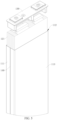
- FIG. 5 is a partial schematic structural exploded view of FIG. 3 observed from another viewing angle.
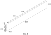
- the battery cell 100 includes: a housing 110, where a dimension of the housing 110 along a length direction is greater than a dimension of the housing 110 along a thickness direction and a dimension of the housing along a width direction, and the housing 110 includes a first board 111 extending along the length direction and an accommodation space 112 opened from at least one end; an electrode assembly 120, disposed in the accommodation space 112; and a cover 130, configured to cover the opening.
- a pressure relief mechanism 140 is disposed on the first board 111. The pressure relief mechanism 140 is configured to be actuated to relieve an internal pressure when the internal pressure or temperature of the housing 110 reaches a threshold. In the length direction, an extension dimension of the pressure relief mechanism 140 is 1/4 of an extension dimension of the first board 111.
- the cover 130 may be fixed to the opening of the housing 110.
- the cover 130 may be welded to the opening of the housing 110.
- the accommodation space 112 may be opened from one end, and the cover 130 is configured to cover the opening.
- the accommodation space 112 may be opened from both ends. That is, the accommodation space 112 includes two openings.
- the cover 130 may be two in number, and each cover 130 is configured to cover a corresponding opening.
- the battery cell 100 includes the housing 110, the electrode assembly 120 located inside the accommodation space 112 of the housing 110, and the cover 130 configured to cover the opening.
- the housing 110 includes the first board 111 extending in the length direction.
- the dimension of the housing 110 along the length direction is greater than the dimension of the housing 110 along the thickness direction and the dimension along the width direction. Therefore, the length of the first board 111 is relatively large.
- the pressure relief mechanism 140 is disposed on the first board 111.
- the extension dimension of the pressure relief mechanism 140 is greater than or equal to 1 ⁇ 4 of the extension dimension of the first board 111. Due to the relatively large length of the first board 111, the pressure relief mechanism 140 can be disposed long enough to meet the pressure relief requirements of the battery cell.
- the dimension of the housing 110 in the width direction and the thickness direction is relatively small. Therefore, a distance for conveying gas in the battery cell 100 to the pressure relief mechanism 140 is relatively short, thereby reducing hazards of explosion caused by inability to exhaust the gas inside the battery cell 100 in time, and improving the safety performance of the battery cell 100.
- the pressure relief mechanism 140 may be disposed in various ways.
- the pressure relief mechanism 140 may be a temperature-sensitive pressure relief mechanism.
- the temperature-sensitive pressure relief mechanism is configured to melt when the internal temperature of the battery cell 100 equipped with the pressure relief mechanism 140 reaches a threshold; and/or, the pressure relief mechanism 140 may be a pressure-sensitive pressure relief mechanism.
- the pressure-sensitive pressure relief mechanism is configured to rupture when the internal air pressure of the battery cell 100 equipped with the pressure relief mechanism 140 reaches a threshold.
- the pressure relief mechanism 140 may be a thin-walled structure.
- the structural strength of the position at which the pressure relief mechanism 140 is located is less than the structural strength of other positions of the first board 111. In this way, when the internal air pressure of the battery cell 100 reaches the threshold, the pressure relief mechanism 140 is ruptured before other positions of the first board 111. Therefore, the gas can be exhausted from the pressure relief mechanism 140.
- the shape of the pressure relief mechanism 140 is diversified.
- the pressure relief mechanism 140 may be in any appropriate shape as long as the extension dimension of the pressure relief mechanism 140 is greater than or equal to 1/4 of the extension dimension of the first board 111 in the length direction.
- the pressure relief mechanism 140 is strip-shaped. Even if the width of the first board 111 is relatively small, the pressure relief mechanism 140 can still be accommodated.
- the pressure relief mechanism 140 may be disposed on a board that is relatively small in area on the housing 110, so that the housing 110 can be in various shapes.
- the pressure relief mechanism 140 can still be disposed on the housing 110.
- the housing 110 further includes a second board 113 extending along the length direction.
- the second board 113 intersects the first board 111.
- the first board 111 is perpendicular to the width direction.
- the second board 113 is perpendicular to the thickness direction.
- the area of the first board 111 is less than the area of the second board 113.
- the area of the first board 111 is less than the area of the second board 113, and the pressure relief mechanism 140 is disposed on the first board 111 that is smaller in area.
- the plurality of battery cells 100 can be stacked oppositely on the second board 113 that is larger in area, thereby reducing the extension dimension of the plurality of battery cells 100 in the thickness direction and simplifying the structure of the battery 10.
- the housing 110 includes two second boards 113 disposed opposite to each other along the thickness direction, and two first boards 111 disposed opposite to each other along the width direction.
- the two first boards 111 and the two second boards 113 are alternately connected to each other in tandem, and close in to form the accommodation space 112.
- the electrode assembly 120 may be disposed in various ways.
- the electrode assembly 120 is formed by winding an electrode plate 121.
- the electrode assembly 120 includes a plurality of electrode plates 121 stacked along the thickness direction.
- the electrode plates 121 are stacked together with the second board 113 along the thickness direction.
- positions of the electrode plates 121 are shown by dashed lines. The dashed lines do not constitute a structural limitation on the embodiments of this application.
- the electrode plates 121 are stacked together with the second board 113 along the thickness direction, so that a gap between two adjacent electrode plates 121 can be disposed opposite to the first board 111.
- hot gas in the battery cell 100 is usually generated between the two adjacent electrode plates 121.
- the gap between the two adjacent electrode plates 121 is opposite to the first board 111. That is, the gap between the two adjacent electrode plates 121 is disposed opposite to the pressure relief mechanism 140. In this way, the hot gas can be exhausted quickly through the pressure relief mechanism 140 to avoid a major safety accident.
- the length of the pressure relief mechanism 140 may be set in various ways.
- the extension dimension of the pressure relief mechanism 140 is equal to the extension dimension of the first board 111.
- the pressure relief mechanism 140 is located in a middle region of the first board 111.
- the pressure relief mechanism 140 is located in the middle region of the first board 111 in the thickness direction; and/or, when the extension dimension of the pressure relief mechanism 140 in the length direction is less than the extension dimension of the first board 111 in the length direction, the pressure relief mechanism 140 is located in the middle region of the first board 111 in the length direction. In this way, distances from different positions in the housing 110 to the pressure relief mechanism 140 tend to be identical, thereby avoiding a major safety accident caused by a high pressure at a partial position in the housing 110.
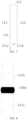
- FIG. 6 is a side view of a battery cell 100 according to an embodiment of this application.
- FIG. 7 is a sectional view of the drawing in FIG. 6 along an A-A section line.
- FIG. 8 is a partial enlarged view of position I in FIG. 7 .
- the first board 111 includes a first part 111a and a second part 111b that are arranged side by side.
- the first part 111a is fixed to the second part 111b by welding.
- a weld 140a is formed at a joint between the first part 111a and the second part 111b.
- the weld 140a is the pressure relief mechanism 140.
- the pressure relief mechanism 140 is the weld 140a formed during welding between the first part 111a and the second part 111b.
- the pressure relief mechanism 140 is disposed in a simple way, and is formed conveniently, thereby improving efficiency of preparing the battery cell 100.
- the weld 140a is formed by welding the first part 111a and the second part 111b with solder, for example.
- the weld 140a runs through the first board 111 along the length direction. That is, a joint gap that runs through the first board along the length direction exists between the first part 111a and the second part 111b. In this way, the dimension of the pressure relief mechanism 140 is large enough, thereby further improving the safety performance of the battery cell 100.
- the first board 111 extends along the thickness direction
- the first board 111 includes a first part 111a and a second part 111b that are arranged side by side along the thickness direction. The first part 111a is welded to the second part 111b to form the weld 140a.
- the extension dimension of the weld 140a in the width direction is 1 mm to 3 mm.
- an oversized weld 140a is avoided.
- the oversized weld results in insufficient structural strength of the position at which the weld 140a is located, makes the battery cell 100 prone to be damaged, and leads to leakage of the electrolytic solution in the housing.
- an undersized weld 140a is avoided.
- the undersized weld results in excessive structural strength of the position at which the weld 140a is located. Consequently, the weld 140a is unable to be ruptured to relieve the internal pressure when the internal pressure or temperature in the battery cell 100 reaches the threshold.
- the housing 110 includes, for example, a side board and a bottom board 114.
- the bottom board 114 is disposed opposite to an opening.
- the side board closes in to form the opening.
- the side board includes the first board 111. When the first part 111a is fully separated from the second part 1 11b, the side board may be formed by bending a whole sheet of panel.
- the electrode assembly 120 When the extension length of the battery cell 100 in the length direction is relatively large, the operation of disposing the electrode assembly 120 into the accommodation space 112 from the opening is relatively difficult.
- the electrode assembly 120 may be disposed on the side board first, and then the side board is bent so that the side board encloses the electrode assembly 120. This can reduce the difficulty of operation and improve the efficiency of forming the battery cell 100.
- FIG. 9 is a sectional view along an A-A section line in FIG. 6 according to another embodiment of this application.
- FIG. 10 is a partially enlarged schematic structural diagram of position II in FIG. 9 .
- the pressure relief mechanism 140 is a notch groove 140b disposed on the first board 111.
- the notch groove 140b can reduce structural strength of a position at which the notch groove is located.
- the notch groove 140b is ruptured first before other positions of the first board 111. Therefore, the internal pressure of the housing 110 can be relieved through a gap generated by the ruptured notch groove 140b.
- the notch groove 140b is disposed on an outer surface that is of the first board 111 and that faces back from the accommodation space 112. This prevents the electrode assembly 120 from being scratched by edges and corners formed on the surface of the first board 111 by the notch groove 140b.
- the dimension of the notch groove 140b is not limited.
- a corresponding dimension of the first board 111 at the notch groove 140b is 1/4 to 3/4 of a dimension of the first board 111 in other regions.
- an opening width of the notch groove 140b is 1 mm to 3 mm.
- the width of the notch groove 140b falls within the foregoing range, it is avoided that, because the structural strength of the position at which the notch groove 140b is located is insufficient due to an oversized notch groove 140b, the housing is prone to be damaged, resulting in leakage of the electrolytic solution in the housing. It is also avoided that, because the structural strength of the position at which the notch groove 140b is located is excessive due to an undersized notch groove 140b, the notch groove 140b is unable to be ruptured to release the internal pressure when the internal pressure or temperature of the housing 110 reaches the threshold.
- a cross section of an inner surface of the notch groove 140b is V-shaped or arc-shaped to facilitate the formation of the notch groove 140b.
Landscapes
- Chemical & Material Sciences (AREA)
- Chemical Kinetics & Catalysis (AREA)
- Electrochemistry (AREA)
- General Chemical & Material Sciences (AREA)
- Engineering & Computer Science (AREA)
- Manufacturing & Machinery (AREA)
- Gas Exhaust Devices For Batteries (AREA)
- Battery Mounting, Suspending (AREA)
- Sealing Battery Cases Or Jackets (AREA)
Claims (11)
- Cellule de batterie (100), comprenant :un boîtier (110), une dimension du boîtier (110) le long d'une direction de longueur étant supérieure à une dimension du boîtier (110) le long d'une direction d'épaisseur et une dimension du boîtier (110) le long d'une direction de largeur, et le boîtier (110) comprenant une première tôle (111) s'étendant le long de la direction de longueur et un espace de logement (112) ouvert depuis au moins une extrémité ;un ensemble électrode (120), disposé dans l'espace de logement (112) ;un couvercle (130), conçu pour couvrir l'ouverture,dans laquelle, un mécanisme de libération de pression (140) est disposé sur la première tôle (111), le mécanisme de libération de pression (140) est conçu pour être actionné afin de libérer une pression interne quand la pression ou la température internes du boîtier (110) atteint un seuil, et, dans la direction de longueur, une dimension d'extension du mécanisme de libération de pression (140) est supérieure ou égale à 1/4 d'une dimension d'extension de la première tôle (111) ; etcaractérisée en ce que la première tôle (111) comprend une première partie (111a) et une deuxième partie (111b) qui sont agencées côte à côte, la première partie (111a) étant fixée à la deuxième partie (111b) par soudage, une soudure (140a) étant formée au niveau d'une jonction entre la première partie (111a) et la deuxième partie (111b), et la soudure (140a) constituant le mécanisme de libération de pression (140).
- Cellule de batterie (100) selon la revendication 1, dans laquelle le mécanisme de libération de pression (140) est situé dans une région centrale de la première tôle (111).
- Cellule de batterie (100) selon la revendication 1, dans laquelle la soudure (140a) s'étend à travers la première tôle (111) le long de la direction de longueur.
- Cellule de batterie (100) selon la revendication 1, dans laquelle le mécanisme de libération de pression (140) est une rainure d'encoche (140b) disposée sur la première tôle (111).
- Cellule de batterie (100) selon la revendication 4, dans laquelle la rainure d'encoche (140b) est disposée sur une surface externe qui appartient à la première tôle (111) et qui est orientée à l'opposé de l'espace de logement (112).
- Cellule de batterie (100) selon la revendication 4, dans laquelle, le long d'une direction perpendiculaire à la première tôle (111), une dimension correspondante de la première tôle (111) au niveau de la rainure d'encoche (140b) est de 1/4 à 3/4 d'une dimension de la première tôle (111) dans d'autres régions.
- Cellule de batterie (100) selon l'une quelconque des revendications 1 à 6, dans laquelle le boîtier (110) comprend en outre une deuxième tôle (113) s'étendant le long de la direction de longueur, la deuxième tôle (113) intersecte la première tôle (111), la première tôle (111) est perpendiculaire à la direction de largeur, la deuxième tôle (113) est perpendiculaire à la direction d'épaisseur, et une aire de la première tôle (111) est inférieure à une aire de la deuxième tôle (113).
- Cellule de batterie (100) selon la revendication 7, dans laquelle l'ensemble électrode (120) comprend une pluralité de plaques d'électrode (121) empilées le long de la direction d'épaisseur, et les plaques d'électrode (121) sont empilées ensemble avec la deuxième tôle (113) le long de la direction d'épaisseur.
- Batterie (10), comprenant :
la cellule de batterie (100) selon l'une quelconque des revendications 1 à 8, dans laquelle une pluralité des cellules de batterie (100) sont agencées côte à côte le long de la direction d'épaisseur, la direction de longueur et la direction d'épaisseur étant toutes deux parallèles à une direction horizontale, et la direction de largeur étant parallèle à une direction verticale. - Batterie (10) selon la revendication 9, dans laquelle la première tôle (111) est située au niveau d'un fond des cellules de batterie (100) le long de la direction verticale.
- Dispositif électrique, comprenant la batterie (10) selon la revendication 9 ou 10.
Applications Claiming Priority (2)
| Application Number | Priority Date | Filing Date | Title |
|---|---|---|---|
| CN202022719459.0U CN213692271U (zh) | 2020-11-20 | 2020-11-20 | 电池单体、电池及用电装置 |
| PCT/CN2020/139130 WO2022105010A1 (fr) | 2020-11-20 | 2020-12-24 | Élément de batterie, batterie et dispositif consommateur d'énergie |
Publications (4)
| Publication Number | Publication Date |
|---|---|
| EP4080661A1 EP4080661A1 (fr) | 2022-10-26 |
| EP4080661A4 EP4080661A4 (fr) | 2024-01-10 |
| EP4080661C0 EP4080661C0 (fr) | 2024-12-25 |
| EP4080661B1 true EP4080661B1 (fr) | 2024-12-25 |
Family
ID=76734436
Family Applications (1)
| Application Number | Title | Priority Date | Filing Date |
|---|---|---|---|
| EP20962301.6A Active EP4080661B1 (fr) | 2020-11-20 | 2020-12-24 | Élément de batterie, batterie et dispositif consommateur d'énergie |
Country Status (7)
| Country | Link |
|---|---|
| US (1) | US20230006304A1 (fr) |
| EP (1) | EP4080661B1 (fr) |
| JP (1) | JP7428811B2 (fr) |
| KR (1) | KR102763098B1 (fr) |
| CN (2) | CN213692271U (fr) |
| HU (1) | HUE070372T2 (fr) |
| WO (1) | WO2022105010A1 (fr) |
Families Citing this family (14)
| Publication number | Priority date | Publication date | Assignee | Title |
|---|---|---|---|---|
| CN213692271U (zh) * | 2020-11-20 | 2021-07-13 | 宁德时代新能源科技股份有限公司 | 电池单体、电池及用电装置 |
| KR102857146B1 (ko) * | 2021-07-29 | 2025-09-10 | 컨템포러리 엠퍼렉스 테크놀로지 (홍콩) 리미티드 | 배터리 셀 및 그 제조방법과 제조 시스템, 배터리 및 전기장치 |
| HUE071288T2 (hu) * | 2021-07-29 | 2025-08-28 | Contemporary Amperex Technology Hong Kong Ltd | Akkumulátorcella, gyártási eljárás és ehhez való gyártási rendszer, akkumulátor és elektromos berendezés |
| CN116315355A (zh) * | 2022-01-07 | 2023-06-23 | 江苏时代新能源科技有限公司 | 电池及用电装置 |
| WO2023130358A1 (fr) * | 2022-01-07 | 2023-07-13 | 宁德时代新能源科技股份有限公司 | Élément de batterie, son procédé de fabrication et son dispositif de fabrication, batterie et dispositif électrique |
| CN218005148U (zh) * | 2022-06-21 | 2022-12-09 | 湖北亿纬动力有限公司 | 一种电池壳体及电池 |
| CN115832394A (zh) * | 2022-11-07 | 2023-03-21 | 深圳市比克动力电池有限公司 | 卷芯、电池、卷芯的制造方法及电池的制造方法 |
| WO2024174257A1 (fr) * | 2023-02-24 | 2024-08-29 | 宁德时代新能源科技股份有限公司 | Boîtier, élément de batterie, batterie et dispositif alimenté |
| JP7768197B2 (ja) * | 2023-06-27 | 2025-11-12 | トヨタ自動車株式会社 | 二次電池 |
| CN116706416B (zh) * | 2023-08-07 | 2023-10-13 | 蜂巢能源科技股份有限公司 | 一种动力电池及电池包 |
| JP7748427B2 (ja) * | 2023-09-27 | 2025-10-02 | プライムプラネットエナジー&ソリューションズ株式会社 | 二次電池 |
| CN117578007B (zh) * | 2023-11-30 | 2025-01-21 | 蜂巢能源科技股份有限公司 | 电池壳体及电池 |
| JP2025185321A (ja) * | 2024-06-10 | 2025-12-22 | プライムプラネットエナジー&ソリューションズ株式会社 | 蓄電デバイス |
| CN118676495B (zh) * | 2024-08-20 | 2024-11-29 | 蜂巢能源科技股份有限公司 | 电芯外壳及电芯 |
Family Cites Families (14)
| Publication number | Priority date | Publication date | Assignee | Title |
|---|---|---|---|---|
| JPS59154744A (ja) * | 1983-02-23 | 1984-09-03 | Hitachi Maxell Ltd | 密閉型電池 |
| JP3863351B2 (ja) * | 2000-02-18 | 2006-12-27 | 松下電器産業株式会社 | 角形電池および角形電池の安全機構の製造方法 |
| KR100515356B1 (ko) * | 2003-06-19 | 2005-09-15 | 삼성에스디아이 주식회사 | 이차 전지 및 이의 안전변 제조 방법 |
| JP4535699B2 (ja) * | 2003-07-17 | 2010-09-01 | 三洋電機株式会社 | 開裂溝付き密閉型電池 |
| KR100551885B1 (ko) * | 2003-10-20 | 2006-02-10 | 삼성에스디아이 주식회사 | 리튬 이온 2차 전지 |
| CN101369674A (zh) * | 2007-08-13 | 2009-02-18 | 黄穗阳 | 安全高能折壳锂离子电池及其生产工艺 |
| EP3180811B1 (fr) * | 2014-09-30 | 2018-01-31 | BYD Company Limited | Dispositif de logement de batterie et module de batterie comprenant celui-ci |
| CN208706688U (zh) * | 2018-09-30 | 2019-04-05 | 联动天翼新能源有限公司 | 防爆锂离子电池壳体 |
| KR102654288B1 (ko) * | 2019-01-09 | 2024-04-05 | 비와이디 컴퍼니 리미티드 | 배터리 팩, 차량, 및 에너지 저장 디바이스 |
| CN209344138U (zh) * | 2019-02-14 | 2019-09-03 | 南京优仁有色金属有限公司 | 一种新能源汽车电池壳 |
| CN210245599U (zh) * | 2019-07-16 | 2020-04-03 | 常州微宙电子科技有限公司 | 一种针式锂离子电池 |
| CN211907482U (zh) * | 2020-03-27 | 2020-11-10 | 湖北亿纬动力有限公司 | 电池外壳、电池及电池模组 |
| CN212136523U (zh) * | 2020-05-25 | 2020-12-11 | 上海比耐信息科技有限公司 | 一种高安全的大容量电池 |
| CN213692271U (zh) * | 2020-11-20 | 2021-07-13 | 宁德时代新能源科技股份有限公司 | 电池单体、电池及用电装置 |
-
2020
- 2020-11-20 CN CN202022719459.0U patent/CN213692271U/zh active Active
- 2020-12-24 JP JP2022544071A patent/JP7428811B2/ja active Active
- 2020-12-24 EP EP20962301.6A patent/EP4080661B1/fr active Active
- 2020-12-24 CN CN202080094505.2A patent/CN115039279A/zh active Pending
- 2020-12-24 HU HUE20962301A patent/HUE070372T2/hu unknown
- 2020-12-24 WO PCT/CN2020/139130 patent/WO2022105010A1/fr not_active Ceased
- 2020-12-24 KR KR1020227025589A patent/KR102763098B1/ko active Active
-
2022
- 2022-09-09 US US17/942,088 patent/US20230006304A1/en active Pending
Also Published As
| Publication number | Publication date |
|---|---|
| CN115039279A (zh) | 2022-09-09 |
| JP7428811B2 (ja) | 2024-02-06 |
| EP4080661A1 (fr) | 2022-10-26 |
| WO2022105010A1 (fr) | 2022-05-27 |
| KR102763098B1 (ko) | 2025-02-05 |
| EP4080661C0 (fr) | 2024-12-25 |
| EP4080661A4 (fr) | 2024-01-10 |
| JP2023512947A (ja) | 2023-03-30 |
| HUE070372T2 (hu) | 2025-06-28 |
| CN213692271U (zh) | 2021-07-13 |
| KR20220119696A (ko) | 2022-08-30 |
| US20230006304A1 (en) | 2023-01-05 |
Similar Documents
| Publication | Publication Date | Title |
|---|---|---|
| EP4080661B1 (fr) | Élément de batterie, batterie et dispositif consommateur d'énergie | |
| JP7799802B2 (ja) | 電池セル及びその製造方法並びに製造システム、電池及び電力消費装置 | |
| JP7422789B2 (ja) | 電池、その関連装置、製造方法及び製造機器 | |
| EP4439838A1 (fr) | Élément de batterie, batterie et dispositif électrique | |
| EP3958388B1 (fr) | Batterie et dispositif électrique | |
| US12597676B2 (en) | Battery cell, method and system for manufacturing battery cell, battery, and electrical device | |
| US12394859B2 (en) | Battery, power consumption device, method and device for producing battery | |
| US20240372207A1 (en) | Box of battery, battery, power consumption apparatus, and method and apparatus for producing battery | |
| US11817601B2 (en) | Battery, power consumption device, method and device for producing battery | |
| US12206138B2 (en) | Bus member, battery and power consumption device | |
| EP4485655A1 (fr) | Batterie et dispositif électrique | |
| US20240363960A1 (en) | Battery, electrical device, and method and equipment for manufacturing battery | |
| JP2026500303A (ja) | 電池セル、電池及び電力消費機器 | |
| EP4376147A1 (fr) | Batterie, dispositif électrique, et procédé et dispositif de préparation de batterie | |
| US20250079535A1 (en) | Electrode assembly, battery cell, battery, and electrical device | |
| US20240204341A1 (en) | Battery cell, battery cell manufacturing method and equipment, battery, and electrical device | |
| RU2835923C2 (ru) | Ящик батареи, батарея, энергопотребляющее устройство, а также способ и устройство для изготовления батареи |
Legal Events
| Date | Code | Title | Description |
|---|---|---|---|
| STAA | Information on the status of an ep patent application or granted ep patent |
Free format text: STATUS: THE INTERNATIONAL PUBLICATION HAS BEEN MADE |
|
| PUAI | Public reference made under article 153(3) epc to a published international application that has entered the european phase |
Free format text: ORIGINAL CODE: 0009012 |
|
| STAA | Information on the status of an ep patent application or granted ep patent |
Free format text: STATUS: REQUEST FOR EXAMINATION WAS MADE |
|
| 17P | Request for examination filed |
Effective date: 20220721 |
|
| AK | Designated contracting states |
Kind code of ref document: A1 Designated state(s): AL AT BE BG CH CY CZ DE DK EE ES FI FR GB GR HR HU IE IS IT LI LT LU LV MC MK MT NL NO PL PT RO RS SE SI SK SM TR |
|
| A4 | Supplementary search report drawn up and despatched |
Effective date: 20231213 |
|
| RIC1 | Information provided on ipc code assigned before grant |
Ipc: H01M 50/375 20210101ALI20231207BHEP Ipc: H01M 50/143 20210101ALI20231207BHEP Ipc: H01M 50/133 20210101ALI20231207BHEP Ipc: H01M 50/103 20210101ALI20231207BHEP Ipc: H01M 10/0585 20100101ALI20231207BHEP Ipc: H01M 50/342 20210101AFI20231207BHEP |
|
| DAV | Request for validation of the european patent (deleted) | ||
| DAX | Request for extension of the european patent (deleted) | ||
| RAP1 | Party data changed (applicant data changed or rights of an application transferred) |
Owner name: CONTEMPORARY AMPEREX TECHNOLOGY(HONG KONG) LIMITED |
|
| GRAP | Despatch of communication of intention to grant a patent |
Free format text: ORIGINAL CODE: EPIDOSNIGR1 |
|
| STAA | Information on the status of an ep patent application or granted ep patent |
Free format text: STATUS: GRANT OF PATENT IS INTENDED |
|
| INTG | Intention to grant announced |
Effective date: 20241009 |
|
| GRAS | Grant fee paid |
Free format text: ORIGINAL CODE: EPIDOSNIGR3 |
|
| GRAA | (expected) grant |
Free format text: ORIGINAL CODE: 0009210 |
|
| STAA | Information on the status of an ep patent application or granted ep patent |
Free format text: STATUS: THE PATENT HAS BEEN GRANTED |
|
| AK | Designated contracting states |
Kind code of ref document: B1 Designated state(s): AL AT BE BG CH CY CZ DE DK EE ES FI FR GB GR HR HU IE IS IT LI LT LU LV MC MK MT NL NO PL PT RO RS SE SI SK SM TR |
|
| REG | Reference to a national code |
Ref country code: GB Ref legal event code: FG4D |
|
| REG | Reference to a national code |
Ref country code: CH Ref legal event code: EP |
|
| REG | Reference to a national code |
Ref country code: DE Ref legal event code: R096 Ref document number: 602020043886 Country of ref document: DE |
|
| REG | Reference to a national code |
Ref country code: IE Ref legal event code: FG4D |
|
| U01 | Request for unitary effect filed |
Effective date: 20250117 |
|
| U07 | Unitary effect registered |
Designated state(s): AT BE BG DE DK EE FI FR IT LT LU LV MT NL PT RO SE SI Effective date: 20250123 |
|
| PG25 | Lapsed in a contracting state [announced via postgrant information from national office to epo] |
Ref country code: HR Free format text: LAPSE BECAUSE OF FAILURE TO SUBMIT A TRANSLATION OF THE DESCRIPTION OR TO PAY THE FEE WITHIN THE PRESCRIBED TIME-LIMIT Effective date: 20241225 |
|
| PG25 | Lapsed in a contracting state [announced via postgrant information from national office to epo] |
Ref country code: NO Free format text: LAPSE BECAUSE OF FAILURE TO SUBMIT A TRANSLATION OF THE DESCRIPTION OR TO PAY THE FEE WITHIN THE PRESCRIBED TIME-LIMIT Effective date: 20250325 |
|
| PG25 | Lapsed in a contracting state [announced via postgrant information from national office to epo] |
Ref country code: GR Free format text: LAPSE BECAUSE OF FAILURE TO SUBMIT A TRANSLATION OF THE DESCRIPTION OR TO PAY THE FEE WITHIN THE PRESCRIBED TIME-LIMIT Effective date: 20250326 |
|
| PG25 | Lapsed in a contracting state [announced via postgrant information from national office to epo] |
Ref country code: RS Free format text: LAPSE BECAUSE OF FAILURE TO SUBMIT A TRANSLATION OF THE DESCRIPTION OR TO PAY THE FEE WITHIN THE PRESCRIBED TIME-LIMIT Effective date: 20250325 |
|
| REG | Reference to a national code |
Ref country code: HU Ref legal event code: AG4A Ref document number: E070372 Country of ref document: HU |
|
| PG25 | Lapsed in a contracting state [announced via postgrant information from national office to epo] |
Ref country code: SM Free format text: LAPSE BECAUSE OF FAILURE TO SUBMIT A TRANSLATION OF THE DESCRIPTION OR TO PAY THE FEE WITHIN THE PRESCRIBED TIME-LIMIT Effective date: 20241225 |
|
| PG25 | Lapsed in a contracting state [announced via postgrant information from national office to epo] |
Ref country code: PL Free format text: LAPSE BECAUSE OF FAILURE TO SUBMIT A TRANSLATION OF THE DESCRIPTION OR TO PAY THE FEE WITHIN THE PRESCRIBED TIME-LIMIT Effective date: 20241225 |
|
| PG25 | Lapsed in a contracting state [announced via postgrant information from national office to epo] |
Ref country code: ES Free format text: LAPSE BECAUSE OF FAILURE TO SUBMIT A TRANSLATION OF THE DESCRIPTION OR TO PAY THE FEE WITHIN THE PRESCRIBED TIME-LIMIT Effective date: 20241225 |
|
| PG25 | Lapsed in a contracting state [announced via postgrant information from national office to epo] |
Ref country code: IS Free format text: LAPSE BECAUSE OF FAILURE TO SUBMIT A TRANSLATION OF THE DESCRIPTION OR TO PAY THE FEE WITHIN THE PRESCRIBED TIME-LIMIT Effective date: 20250425 |
|
| PG25 | Lapsed in a contracting state [announced via postgrant information from national office to epo] |
Ref country code: SK Free format text: LAPSE BECAUSE OF FAILURE TO SUBMIT A TRANSLATION OF THE DESCRIPTION OR TO PAY THE FEE WITHIN THE PRESCRIBED TIME-LIMIT Effective date: 20241225 |
|
| PG25 | Lapsed in a contracting state [announced via postgrant information from national office to epo] |
Ref country code: CZ Free format text: LAPSE BECAUSE OF FAILURE TO SUBMIT A TRANSLATION OF THE DESCRIPTION OR TO PAY THE FEE WITHIN THE PRESCRIBED TIME-LIMIT Effective date: 20241225 |
|
| PLBE | No opposition filed within time limit |
Free format text: ORIGINAL CODE: 0009261 |
|
| STAA | Information on the status of an ep patent application or granted ep patent |
Free format text: STATUS: NO OPPOSITION FILED WITHIN TIME LIMIT |
|
| 26N | No opposition filed |
Effective date: 20250926 |
|
| PGFP | Annual fee paid to national office [announced via postgrant information from national office to epo] |
Ref country code: GB Payment date: 20251211 Year of fee payment: 6 |
|
| PGFP | Annual fee paid to national office [announced via postgrant information from national office to epo] |
Ref country code: HU Payment date: 20251209 Year of fee payment: 6 |
|
| U20 | Renewal fee for the european patent with unitary effect paid |
Year of fee payment: 6 Effective date: 20251217 |