EP4080791B1 - Verfahren zum betrieb eines akustischen übertragungssystems zur optimierung der übertragenen leistung - Google Patents
Verfahren zum betrieb eines akustischen übertragungssystems zur optimierung der übertragenen leistung Download PDFInfo
- Publication number
- EP4080791B1 EP4080791B1 EP22162402.6A EP22162402A EP4080791B1 EP 4080791 B1 EP4080791 B1 EP 4080791B1 EP 22162402 A EP22162402 A EP 22162402A EP 4080791 B1 EP4080791 B1 EP 4080791B1
- Authority
- EP
- European Patent Office
- Prior art keywords
- receiver
- load
- frequency
- emitter
- electrical
- Prior art date
- Legal status (The legal status is an assumption and is not a legal conclusion. Google has not performed a legal analysis and makes no representation as to the accuracy of the status listed.)
- Active
Links
Images

Classifications
-
- H—ELECTRICITY
- H02—GENERATION; CONVERSION OR DISTRIBUTION OF ELECTRIC POWER
- H02J—ELECTRIC POWER NETWORKS; CIRCUIT ARRANGEMENTS OR SYSTEMS FOR SUPPLYING OR DISTRIBUTING ELECTRIC POWER; SYSTEMS FOR STORING ELECTRIC ENERGY
- H02J50/00—Circuit arrangements or systems for wireless supply or distribution of electric power
- H02J50/15—Circuit arrangements or systems for wireless supply or distribution of electric power using ultrasonic waves
-
- H—ELECTRICITY
- H04—ELECTRIC COMMUNICATION TECHNIQUE
- H04B—TRANSMISSION
- H04B11/00—Transmission systems employing ultrasonic, sonic or infrasonic waves
Definitions
- the present invention relates to the general field of transmission systems using acoustic waves.
- information and/or energy is transmitted between a transmitter and a receiver acoustically. Information and/or energy are thus transmitted wirelessly and without contact.
- a solution that can be used in certain applications consists of drilling a hole in the wall to pass wires through. This solution requires maintenance and can weaken the structure.
- receivers are used for power transmission when it is desired to electrically power the receiver(s), in particular physically isolated sensors and their communication system, such as for example in tanks or pipes under strong pressures.
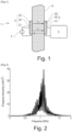
- figure 1 Such an acoustic transmission system for power transmission.
- This system 1 comprises an acoustic transmitter 2 and an acoustic receiver 3 in contact on either side of a metal wall P.
- the acoustic transmitter 2 consists of a piezoelectric disk 20 interposed between two electrodes 21, 22.
- the acoustic receiver 2 also consists of a piezoelectric disk 30 interposed between two electrodes 31, 32.
- An electrical power source 4 is connected to the two electrodes 21, 22 of the transmitter 2.
- the two electrodes 31, 32 of the receiver are connected to an electronic unit 5 adapted to manage the electrical power and which includes a sensor node.
- the operation of such a system 1 is as follows:
- the electrical power from the source 4 is transmitted by applying a sinusoidal voltage to the electrodes 21, 22 which cause the piezoelectric disk 20 to mechanically vibrate.
- the mechanical deformations resulting from this voltage propagate in the thickness of the metal wall P and are transmitted to the piezoelectric disk 30 of the receiver 3 which are therefore converted into electricity.
- the electronic unit 5 can manage the electrical power received.
- the inventors analyzed that to maximize the transmitted acoustic power, it was wise to determine both the optimal frequency and the electrical load to be connected at the acoustic receiver.
- US2015/0049587 suggests choosing the frequency allowing the highest voltage on the storage capacity connected to the receiver. This requires having previously established communication so that the receiver can send the capacity charge level. In addition, this solution does not make it possible to determine the electrical load to be connected.
- US2014/0016558 characterizes the acoustic system prior to any transmission.
- the optimal electrical load to connect to the receiver is determined initially with a vector network analyzer. This involves having physical access to both sides of the metal wall, which is not systematically achievable depending on the applications. Furthermore, this determination made initially is no longer necessarily valid during operation, and if conditions change, for example in the event of a change in temperature.
- the frequency is chosen by communicating to the transmitter the power received by the receiver. However, this implies having previously established communication so that the receiver can communicate data.
- US2010/0027379 describes an operation in which the frequency determined is by the greatest amplitude of the signal received. This requires having previously established communication so that the receiver can send the amplitude of the signal received. No determination of electrical load to be connected is made.
- the existing solutions described above do not make it possible to choose the optimal frequency to maximize power transmission without data communication being previously established with the receiver, nor do they make it possible to choose the electrical load to be connected to the receiver level, before and during operation, also to maximize power transmission.
- An aim of the invention is to respond, at least partially, to this need.
- the acoustic system can comprise several transmitters and several acoustic receivers.
- each receiver is sized to be powered in a frequency range different from the other receivers.
- the dimensions of the receiver can be adjusted to resonate at a frequency within a predetermined frequency range.
- the method can then be performed in each of the respective frequency ranges to determine the characteristic frequency (fopt) which maximizes the transmitted power, receiver voltage or efficiency, for each of the receivers.
- the support is a particularly metallic wall, the transmitter and the receiver being arranged on the same side or on either side of the wall.
- the method according to the invention can be implemented for an acoustic transmission system through a support in any material which typically has a characteristic acoustic impedance of between 1 and 100 MRayl.
- the distinct electrical charges connected to the receiver during step ii/ are respectively an infinite charge corresponding to an open electrical circuit at the receiver, a charge of known value, and a zero charge corresponding to a short circuit at the receiver.
- the duration between each frequency scan is defined by the receiver which waits for a predefined duration, known to the transmitter.
- the duration between each frequency scan is defined by the receiver which indicates to the transmitter by an alternation of the connected load that it is ready, then changes the connected electrical load.
- the duration between each frequency sweep is defined by a change in the impedance on the transmitter side without active components on the receiver side.
- the invention essentially consists of a system for the transmission of acoustic power, which will determine the optimal frequency and electrical charge without data communication being previously established with the receiver.
- This adjustment can be made either by repeating the method described above, or through the communication then established between the transmitter and the receiver, allowing the sending of data describing the quality of the power transmission.
- the invention also relates to the application of the method which has just been described for sending electrical power through a metal wall, in particular a metal wall of a ship, a submarine, a tank, etc. 'a tank, a pipe.
- a method of operating an acoustic transmission system according to the invention is described below, making it possible to maximize the transmitted acoustic power.
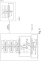
- Step i/ We set up an acoustic transmission system 1 as shown on the figure 1 .
- This system 1 can be characterized as being an electric quadrupole schematized in Figure 3 .
- the inventors therefore thought of making three different measurements to be able to determine the values of Z 11 , Z 12 and Z 22 .
- Z load is the impedance of the load connected to receiver 3 ( Figure 3 ).
- the input impedance of the quadrupole also changes.
- Z 22 Z Load Z in CO ⁇ Z in Z Load Z in Z Load ⁇ Z in CC
- transmitter 2 is permanently supplied with this frequency.
- the transmitter can then trigger the complementary step iii2/ allowing it to determine the optimal electrical load applied to the receiver 3 in order to maximize the transmitted acoustic power.
- the inventors consider that the connected impedance has a significant impact on the recovered power.
- the inventors therefore thought of a method which allows them to overcome this iteration.
- system 1 can be considered as an equivalent electrical diagram obtained by application of Thévenin's theorem, as shown in Figure 4 .
- the first method implies that the receiver must then emit a sinusoidal voltage, which requires quite a lot of energy.
- the second method requiring less energy, the inventors favored it.
- these values can be when the loads are open-circuited and short-circuited.
- the phase between U 2 CO and I 2 CC is important to determine the real and imaginary parts of Z out .
- the optimal impedance to connect at the output can have a reactive component, as already mentioned.
- a difficulty is that the voltage U 2 CO and the current I 2 CC are measured in a time-shifted manner and that moreover, on the receiver side, there is no access to the signal U 1 transmitted.
- the first step consists of maintaining the voltage U 1 at transmitter 2, at a constant frequency for the entire duration of the two measurements, that is to say with the two different loads (open circuit and short circuit) without cutting the signal between the two measurements.
- the second step consists of measuring, on the receiver side 3, during the connection of the first load, the frequency and phase of the signal, the voltage U 2 or the current I 2 . For example, by setting a counter to zero, when U 2 or I 2 passes through zero (in increasing or decreasing value), and by recording the value of the counter at the next zero crossing of this current, in the same direction (increasing or decreasing). decreasing) just before resetting the counter to zero.
- the third step consists, just before disconnecting the first load, of continuing until obtaining the repetition of a phase element as if the signal were continuing.
- the counter is no longer set to zero when the voltage U 2 or the current I 2 crosses zero, but when the counter reaches the value which had been measured/recorded previously at the end of period.
- the phase of the current I 2 and/or the voltage I 2 can be compared to this phase element carried over/repeated. For example, it is possible to measure the temporal or angular distance between the zero crossing of the U 2 and/or I 2 signal with the theoretical zero crossing (when the counter returns to zero) of the U 2 or I 2 signal measured during the first charge as if the signal continued to exist.
- the impedance Z out can then be determined as well as the optimal electrical load.
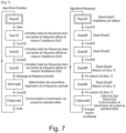
- Steps ii/ and iii/ which have just been described, making it possible to determine the frequency and the load to be connected to maximize the power transmitted to the receiver 3, are synthesized on the Figure 5 .
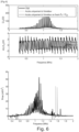
- Steps ii/ and iii1/ were validated experimentally with system 1 on a 60 mm thick aluminum wall.
- the method according to the invention consists of choosing as distinct charges, a infinite charge (open circuit), zero charge (short circuit) and any charge other than infinite and zero.
- the method can be implemented regardless of the electrical loads connected, provided that they are distinct.
- the method detailed above concerns the determination of the frequency making it possible to maximize the transmitted power.
- the knowledge for each frequency of Z 11 , Z 12 and Z 22 makes it possible to predict the behavior of an acoustic transmission system and therefore to operate it with an optimized parameter depending on the desired application.
- the method detailed above is described in relation to acoustic transmission through a metal wall.
- the invention can also be applied to a support made of another material whose characteristic acoustic impedance is typically between 1 and 100 MRayl. It may be, for example, a material chosen from steel, aluminum and other metals, concrete, bitumen, wood, rigid plastics, porcelain, glass, etc.
- the method according to the invention can also be applied to inductive systems with air or with magnetic circuits, as long as the system remains linear, i.e. in small signals (far from the saturation of the magnetic materials).
- the method according to the invention is, however, more suited to the transmission of acoustic power, for which the optimal operating frequencies are difficult to predict, reproducible and strongly dependent on external variables such as temperature.
- the propagation medium is generally air, or otherwise an intermediate controlled/designed by the system designer and there are not as many hazards and impacts of the propagation medium.
- the invention is not limited to the examples which have just been described; In particular, it is possible to combine characteristics of the illustrated examples within non-illustrated variants.
Landscapes
- Engineering & Computer Science (AREA)
- Computer Networks & Wireless Communication (AREA)
- Power Engineering (AREA)
- Signal Processing (AREA)
- Arrangements For Transmission Of Measured Signals (AREA)
- Measurement Of Resistance Or Impedance (AREA)
- Transmitters (AREA)
Claims (13)
- Betriebsverfahren eines akustischen Übertragungssystems, das die folgenden Schritte enthält:
i/ Einsetzen des Systems (1) mit mindestens einem Emitter (2) und mindestens einem akustischen Empfänger (3) auf einem Träger, wobei das System ein elektrischer Vierpol ist, dessen Impedanzmatrix, die die Emitter- (U1) und Empfängerspannungen (U2) mit den Emitter- (I1) und Empfängerströmen (I2) verbindet, gemäß der folgenden Gleichung geschrieben wird: ii/ aufeinanderfolgende dreimalige Frequenzabtastung mit jedes Mal einer mit dem Empfänger Zload verbundenen elektrischen Ladung anders als die vorhergehende, um für jede Frequenz die Werte von Z11, Z12 und von Z22 zu bestimmen,iii/ ausgehend von der Bestimmung der Werte von Z11, Z12 und von Z22, Bestimmung einer charakteristischen Frequenz (fopt), um die übertragene Leistung, die Empfängerspannung (U2) oder den Wirkungsgrad des Systems zu maximieren.
 - Verfahren nach Anspruch 1, wobei der Träger eine insbesondere metallische Wand ist, wobei der Emitter und der Empfänger auf der gleichen Seite oder auf beiden Seiten der Wand angeordnet sind.
- Verfahren nach Anspruch 1 oder 2, wobei die mit dem Empfänger im Schritt ii/ verbundenen verschiedenen elektrischen Ladungen eine unendliche Ladung entsprechend einer für den Empfänger offenen elektrischen Schaltung, eine Ladung bekannten Werts, bzw. eine Ladung Null entsprechend einem Kurzschluss am Empfänger sind.
- Verfahren nach einem der Ansprüche 1 bis 3, wobei die Dauer zwischen jeder Frequenzabtastung vom Empfänger definiert wird, der eine dem Emitter bekannte vordefinierte Dauer wartet.
- Verfahren nach einem der Ansprüche 1 bis 3, wobei die Dauer zwischen jeder Frequenzabtastung vom Empfänger definiert wird, der dem Emitter durch einen Wechsel der verbundenen Ladung anzeigt, dass er bereit ist, dann die verbundene elektrische Ladung ändert.
- Verfahren nach einem der Ansprüche 1 bis 3, wobei die Dauer zwischen jeder Frequenzabtastung von einer Änderung der Impedanz auf der Emitterseite ohne aktive Bauteile auf der Empfängerseite definiert wird.
- Verfahren nach einem der vorhergehenden Ansprüche, wobei der Schritt iii/ die folgenden Teilschritte enthält:iii1/ Bestimmung der charakteristischen Frequenz (fopt) ausgehend von der Bestimmung der bei jeder Frequenz (f) maximal erreichbaren Leistung durch die Beziehung
 iii2/ Anwenden von zwei mit dem Empfänger Zload verbundenen voneinander unterschiedlichen elektrischen Ladungen beim Senden eines sinusförmigen Signals durch den Emitter, um die optimale elektrische Ladung zu bestimmen, ausgehend vom Thévenin-Theorem und der Beziehung
 wobei die Bestimmung der charakteristischen Frequenz und die optimale elektrische Ladung es ermöglichen, die übertragene Leistung zu maximieren.
 - Verfahren nach Anspruch 7, wobei der Schritt iii2/ das Halten der Spannung U1 am Emitter (2) auf einer konstanten Frequenz, das Anwenden einer der zwei unterschiedlichen elektrischen Ladungen ohne Unterbrechung des Signals durch den Emitter enthält.
- Verfahren nach Anspruch 7, wobei der Schritt iii2/ die Messung, auf der Seite des Empfängers (3), während der Verbindung der ersten elektrischen Ladung, der Amplitude des Signals der Spannung U2 oder des Stroms 12 enthält.
- Verfahren nach Anspruch 7, wobei der Schritt iii2/ vor der Trennung der ersten elektrischen Ladung die Wiederholung eines Phasenelements enthält, als ob das sinusförmige Signal fortgesetzt würde.
- Verfahren nach Anspruch 7, wobei der Schritt iii2/ die Anwendung der zweiten elektrischen Ladung enthält.
- Verfahren nach Anspruch 7, wobei der Schritt iii2/ die Messung der Amplitude von U2 oder 12 und der Phase mit dem fortgesetzten Signal vor dem Trennen der ersten Ladung enthält.
- Anwendung des Verfahrens nach einem der vorhergehenden Ansprüche, um elektrische Leistung durch eine metallische Wand hindurch zu schicken, insbesondere eine metallische Wand eines Schiffs, eines U-Boots, eines Reservoirs, eines Tanks, eines Rohrs.
Applications Claiming Priority (1)
| Application Number | Priority Date | Filing Date | Title |
|---|---|---|---|
| FR2102961A FR3121301B1 (fr) | 2021-03-24 | 2021-03-24 | Procédé de fonctionnement d’un système de transmission acoustique permettant d’optimiser la puissance transmise. |
Publications (2)
| Publication Number | Publication Date |
|---|---|
| EP4080791A1 EP4080791A1 (de) | 2022-10-26 |
| EP4080791B1 true EP4080791B1 (de) | 2023-10-04 |
Family
ID=76920848
Family Applications (1)
| Application Number | Title | Priority Date | Filing Date |
|---|---|---|---|
| EP22162402.6A Active EP4080791B1 (de) | 2021-03-24 | 2022-03-16 | Verfahren zum betrieb eines akustischen übertragungssystems zur optimierung der übertragenen leistung |
Country Status (3)
| Country | Link |
|---|---|
| US (1) | US11791661B2 (de) |
| EP (1) | EP4080791B1 (de) |
| FR (1) | FR3121301B1 (de) |
Family Cites Families (9)
| Publication number | Priority date | Publication date | Assignee | Title |
|---|---|---|---|---|
| US20100027379A1 (en) | 2006-10-02 | 2010-02-04 | Gary Saulnier | Ultrasonic Through-Wall Communication (UTWC) System |
| US7902943B2 (en) * | 2007-04-23 | 2011-03-08 | California Institute Of Technology | Wireless acoustic-electric feed-through for power and signal transmission |
| WO2012141891A1 (en) * | 2011-04-12 | 2012-10-18 | Rensselaer Polytechnic Institute | Adaptive system for efficient transmission of power and data through acoustic media |
| CA2868464A1 (en) | 2012-03-29 | 2013-10-03 | Rensselaer Polytechnic Institute | A full-duplex ultrasonic through-wall communication and power delivery system with frequency tracking |
| WO2014018967A1 (en) * | 2012-07-27 | 2014-01-30 | Thoratec Corporation | Self-tuning resonant power transfer systems |
| KR102005781B1 (ko) * | 2013-06-27 | 2019-07-31 | 한국전자통신연구원 | 초음파를 이용한 무선 전력 전송 장치 |
| US10097046B2 (en) * | 2016-03-18 | 2018-10-09 | Global Energy Transmission, Co. | Wireless power assembly |
| US11112523B2 (en) * | 2017-12-01 | 2021-09-07 | Schlumberger Technology Corporation | Calibration of electromagnetic measurement tool |
| FR3091089B1 (fr) | 2018-12-19 | 2022-03-11 | Commissariat Energie Atomique | Dispositif de transmission acoustique |
-
2021
- 2021-03-24 FR FR2102961A patent/FR3121301B1/fr active Active
-
2022
- 2022-03-16 EP EP22162402.6A patent/EP4080791B1/de active Active
- 2022-03-24 US US17/702,911 patent/US11791661B2/en active Active
Also Published As
| Publication number | Publication date |
|---|---|
| FR3121301A1 (fr) | 2022-09-30 |
| US11791661B2 (en) | 2023-10-17 |
| US20220311279A1 (en) | 2022-09-29 |
| FR3121301B1 (fr) | 2023-02-10 |
| EP4080791A1 (de) | 2022-10-26 |
Similar Documents
| Publication | Publication Date | Title |
|---|---|---|
| FR2889375A1 (fr) | Structure resonnante hybride | |
| WO2020221618A1 (fr) | Procede de detection de defauts non francs dans un cable par analyse en composantes principales | |
| EP4314850A1 (de) | Verfahren und system zur schätzung eines alterungsindikators einer wiederaufladbaren elektrischen batterie | |
| WO2016096250A1 (fr) | Procede de determination de parametres d'un filtre de compression et radar multivoies associe | |
| EP4080791B1 (de) | Verfahren zum betrieb eines akustischen übertragungssystems zur optimierung der übertragenen leistung | |
| EP3532832B1 (de) | Verfahren zur zerstörungsfreien prüfung einer verklebten anordnung mittels ultraschall | |
| WO2012085110A1 (fr) | Gestion et estimation de l'etat d'une batterie | |
| FR2858062A1 (fr) | Appareil de mesure de temps de propagation acoustique | |
| WO2012150394A1 (fr) | Ensemble et procede de surveillance pour detecter des defauts structurels pouvant apparaitre dans une nacelle d'aeronef en service | |
| EP3632012B1 (de) | System bestehend aus einer wellenformgebungsvorrichtung und einem wellenempfänger | |
| FR3131146A1 (fr) | Procédé et système de détermination de l’état d’un capteur à travers un support | |
| EP2560130B1 (de) | Abfrageverfahren eines akustischen Oberflächenwellensensors | |
| FR3079928A1 (fr) | Capteur passif differentiel a base de resonateurs a ondes elastiques pour mesure de detection de contact et de mesure de temperature | |
| EP3725099B1 (de) | Verfahren zur erkennung einer fehlfunktion eines mit einem elektrochemischen generator gekoppelten akustischen sensors und vorrichtung zur durchführung des verfahrens | |
| FR3115176A1 (fr) | Dispositif de traitement d’un signal analogique, systeme audio et porte sonorisee de vehicule associes | |
| FR2968770B1 (fr) | Procede et dispositif de saisie d'un objet dans un environnement par un signal d'ultrasons | |
| EP3280987A1 (de) | Steuerungsvorrichtung mit elektronischen knoten mit fähigkeit zur gegenseitigen elektrischen speisung und zur kommunikation miteinander | |
| FR3150302A1 (fr) | Système de mesure de la position d’un contrepoids | |
| FR3017717A1 (fr) | Dispositif de capteur d'environnement avec une adaptation dynamique | |
| EP3670004A1 (de) | Ultraschall-signalwandler mit schwingungsmembran mit kapazitivem breitbandeffekt | |
| EP4480745B1 (de) | System und verfahren zur messung der position eines gegengewichts einer eisenbahn fahrleitung | |
| EP4241400B1 (de) | Empfangsvorrichtung und verfahren für schallwellen | |
| FR2991058A1 (fr) | Dispositif pour supprimer les battements a l'amortissement actif de capteur a ultrasons | |
| CH709293A2 (fr) | Microphone passif. | |
| EP3701572A1 (de) | Wabenstruktur mit einer integritätsüberwachungsvorrichtung und verfahren zur überwachung einer solchen struktur |
Legal Events
| Date | Code | Title | Description |
|---|---|---|---|
| PUAI | Public reference made under article 153(3) epc to a published international application that has entered the european phase |
Free format text: ORIGINAL CODE: 0009012 |
|
| STAA | Information on the status of an ep patent application or granted ep patent |
Free format text: STATUS: REQUEST FOR EXAMINATION WAS MADE |
|
| 17P | Request for examination filed |
Effective date: 20220316 |
|
| AK | Designated contracting states |
Kind code of ref document: A1 Designated state(s): AL AT BE BG CH CY CZ DE DK EE ES FI FR GB GR HR HU IE IS IT LI LT LU LV MC MK MT NL NO PL PT RO RS SE SI SK SM TR |
|
| GRAP | Despatch of communication of intention to grant a patent |
Free format text: ORIGINAL CODE: EPIDOSNIGR1 |
|
| STAA | Information on the status of an ep patent application or granted ep patent |
Free format text: STATUS: GRANT OF PATENT IS INTENDED |
|
| INTG | Intention to grant announced |
Effective date: 20230512 |
|
| GRAS | Grant fee paid |
Free format text: ORIGINAL CODE: EPIDOSNIGR3 |
|
| GRAA | (expected) grant |
Free format text: ORIGINAL CODE: 0009210 |
|
| STAA | Information on the status of an ep patent application or granted ep patent |
Free format text: STATUS: THE PATENT HAS BEEN GRANTED |
|
| AK | Designated contracting states |
Kind code of ref document: B1 Designated state(s): AL AT BE BG CH CY CZ DE DK EE ES FI FR GB GR HR HU IE IS IT LI LT LU LV MC MK MT NL NO PL PT RO RS SE SI SK SM TR |
|
| REG | Reference to a national code |
Ref country code: GB Ref legal event code: FG4D Free format text: NOT ENGLISH |
|
| REG | Reference to a national code |
Ref country code: CH Ref legal event code: EP |
|
| REG | Reference to a national code |
Ref country code: DE Ref legal event code: R096 Ref document number: 602022000603 Country of ref document: DE |
|
| REG | Reference to a national code |
Ref country code: IE Ref legal event code: FG4D Free format text: LANGUAGE OF EP DOCUMENT: FRENCH |
|
| REG | Reference to a national code |
Ref country code: LT Ref legal event code: MG9D |
|
| REG | Reference to a national code |
Ref country code: NL Ref legal event code: MP Effective date: 20231004 |
|
| REG | Reference to a national code |
Ref country code: AT Ref legal event code: MK05 Ref document number: 1618852 Country of ref document: AT Kind code of ref document: T Effective date: 20231004 |
|
| PG25 | Lapsed in a contracting state [announced via postgrant information from national office to epo] |
Ref country code: NL Free format text: LAPSE BECAUSE OF FAILURE TO SUBMIT A TRANSLATION OF THE DESCRIPTION OR TO PAY THE FEE WITHIN THE PRESCRIBED TIME-LIMIT Effective date: 20231004 |
|
| PG25 | Lapsed in a contracting state [announced via postgrant information from national office to epo] |
Ref country code: GR Free format text: LAPSE BECAUSE OF FAILURE TO SUBMIT A TRANSLATION OF THE DESCRIPTION OR TO PAY THE FEE WITHIN THE PRESCRIBED TIME-LIMIT Effective date: 20240105 |
|
| PG25 | Lapsed in a contracting state [announced via postgrant information from national office to epo] |
Ref country code: IS Free format text: LAPSE BECAUSE OF FAILURE TO SUBMIT A TRANSLATION OF THE DESCRIPTION OR TO PAY THE FEE WITHIN THE PRESCRIBED TIME-LIMIT Effective date: 20240204 |
|
| PG25 | Lapsed in a contracting state [announced via postgrant information from national office to epo] |
Ref country code: LT Free format text: LAPSE BECAUSE OF FAILURE TO SUBMIT A TRANSLATION OF THE DESCRIPTION OR TO PAY THE FEE WITHIN THE PRESCRIBED TIME-LIMIT Effective date: 20231004 |
|
| PG25 | Lapsed in a contracting state [announced via postgrant information from national office to epo] |
Ref country code: AT Free format text: LAPSE BECAUSE OF FAILURE TO SUBMIT A TRANSLATION OF THE DESCRIPTION OR TO PAY THE FEE WITHIN THE PRESCRIBED TIME-LIMIT Effective date: 20231004 |
|
| PG25 | Lapsed in a contracting state [announced via postgrant information from national office to epo] |
Ref country code: ES Free format text: LAPSE BECAUSE OF FAILURE TO SUBMIT A TRANSLATION OF THE DESCRIPTION OR TO PAY THE FEE WITHIN THE PRESCRIBED TIME-LIMIT Effective date: 20231004 |
|
| PG25 | Lapsed in a contracting state [announced via postgrant information from national office to epo] |
Ref country code: LT Free format text: LAPSE BECAUSE OF FAILURE TO SUBMIT A TRANSLATION OF THE DESCRIPTION OR TO PAY THE FEE WITHIN THE PRESCRIBED TIME-LIMIT Effective date: 20231004 Ref country code: IS Free format text: LAPSE BECAUSE OF FAILURE TO SUBMIT A TRANSLATION OF THE DESCRIPTION OR TO PAY THE FEE WITHIN THE PRESCRIBED TIME-LIMIT Effective date: 20240204 Ref country code: GR Free format text: LAPSE BECAUSE OF FAILURE TO SUBMIT A TRANSLATION OF THE DESCRIPTION OR TO PAY THE FEE WITHIN THE PRESCRIBED TIME-LIMIT Effective date: 20240105 Ref country code: ES Free format text: LAPSE BECAUSE OF FAILURE TO SUBMIT A TRANSLATION OF THE DESCRIPTION OR TO PAY THE FEE WITHIN THE PRESCRIBED TIME-LIMIT Effective date: 20231004 Ref country code: BG Free format text: LAPSE BECAUSE OF FAILURE TO SUBMIT A TRANSLATION OF THE DESCRIPTION OR TO PAY THE FEE WITHIN THE PRESCRIBED TIME-LIMIT Effective date: 20240104 Ref country code: AT Free format text: LAPSE BECAUSE OF FAILURE TO SUBMIT A TRANSLATION OF THE DESCRIPTION OR TO PAY THE FEE WITHIN THE PRESCRIBED TIME-LIMIT Effective date: 20231004 Ref country code: PT Free format text: LAPSE BECAUSE OF FAILURE TO SUBMIT A TRANSLATION OF THE DESCRIPTION OR TO PAY THE FEE WITHIN THE PRESCRIBED TIME-LIMIT Effective date: 20240205 |
|
| PG25 | Lapsed in a contracting state [announced via postgrant information from national office to epo] |
Ref country code: SE Free format text: LAPSE BECAUSE OF FAILURE TO SUBMIT A TRANSLATION OF THE DESCRIPTION OR TO PAY THE FEE WITHIN THE PRESCRIBED TIME-LIMIT Effective date: 20231004 Ref country code: RS Free format text: LAPSE BECAUSE OF FAILURE TO SUBMIT A TRANSLATION OF THE DESCRIPTION OR TO PAY THE FEE WITHIN THE PRESCRIBED TIME-LIMIT Effective date: 20231004 Ref country code: PL Free format text: LAPSE BECAUSE OF FAILURE TO SUBMIT A TRANSLATION OF THE DESCRIPTION OR TO PAY THE FEE WITHIN THE PRESCRIBED TIME-LIMIT Effective date: 20231004 Ref country code: NO Free format text: LAPSE BECAUSE OF FAILURE TO SUBMIT A TRANSLATION OF THE DESCRIPTION OR TO PAY THE FEE WITHIN THE PRESCRIBED TIME-LIMIT Effective date: 20240104 Ref country code: LV Free format text: LAPSE BECAUSE OF FAILURE TO SUBMIT A TRANSLATION OF THE DESCRIPTION OR TO PAY THE FEE WITHIN THE PRESCRIBED TIME-LIMIT Effective date: 20231004 Ref country code: HR Free format text: LAPSE BECAUSE OF FAILURE TO SUBMIT A TRANSLATION OF THE DESCRIPTION OR TO PAY THE FEE WITHIN THE PRESCRIBED TIME-LIMIT Effective date: 20231004 |
|
| REG | Reference to a national code |
Ref country code: DE Ref legal event code: R097 Ref document number: 602022000603 Country of ref document: DE |
|
| PG25 | Lapsed in a contracting state [announced via postgrant information from national office to epo] |
Ref country code: DK Free format text: LAPSE BECAUSE OF FAILURE TO SUBMIT A TRANSLATION OF THE DESCRIPTION OR TO PAY THE FEE WITHIN THE PRESCRIBED TIME-LIMIT Effective date: 20231004 |
|
| PG25 | Lapsed in a contracting state [announced via postgrant information from national office to epo] |
Ref country code: CZ Free format text: LAPSE BECAUSE OF FAILURE TO SUBMIT A TRANSLATION OF THE DESCRIPTION OR TO PAY THE FEE WITHIN THE PRESCRIBED TIME-LIMIT Effective date: 20231004 |
|
| PG25 | Lapsed in a contracting state [announced via postgrant information from national office to epo] |
Ref country code: SK Free format text: LAPSE BECAUSE OF FAILURE TO SUBMIT A TRANSLATION OF THE DESCRIPTION OR TO PAY THE FEE WITHIN THE PRESCRIBED TIME-LIMIT Effective date: 20231004 |
|
| PG25 | Lapsed in a contracting state [announced via postgrant information from national office to epo] |
Ref country code: SM Free format text: LAPSE BECAUSE OF FAILURE TO SUBMIT A TRANSLATION OF THE DESCRIPTION OR TO PAY THE FEE WITHIN THE PRESCRIBED TIME-LIMIT Effective date: 20231004 Ref country code: SK Free format text: LAPSE BECAUSE OF FAILURE TO SUBMIT A TRANSLATION OF THE DESCRIPTION OR TO PAY THE FEE WITHIN THE PRESCRIBED TIME-LIMIT Effective date: 20231004 Ref country code: RO Free format text: LAPSE BECAUSE OF FAILURE TO SUBMIT A TRANSLATION OF THE DESCRIPTION OR TO PAY THE FEE WITHIN THE PRESCRIBED TIME-LIMIT Effective date: 20231004 Ref country code: IT Free format text: LAPSE BECAUSE OF FAILURE TO SUBMIT A TRANSLATION OF THE DESCRIPTION OR TO PAY THE FEE WITHIN THE PRESCRIBED TIME-LIMIT Effective date: 20231004 Ref country code: EE Free format text: LAPSE BECAUSE OF FAILURE TO SUBMIT A TRANSLATION OF THE DESCRIPTION OR TO PAY THE FEE WITHIN THE PRESCRIBED TIME-LIMIT Effective date: 20231004 Ref country code: DK Free format text: LAPSE BECAUSE OF FAILURE TO SUBMIT A TRANSLATION OF THE DESCRIPTION OR TO PAY THE FEE WITHIN THE PRESCRIBED TIME-LIMIT Effective date: 20231004 Ref country code: CZ Free format text: LAPSE BECAUSE OF FAILURE TO SUBMIT A TRANSLATION OF THE DESCRIPTION OR TO PAY THE FEE WITHIN THE PRESCRIBED TIME-LIMIT Effective date: 20231004 |
|
| PLBE | No opposition filed within time limit |
Free format text: ORIGINAL CODE: 0009261 |
|
| STAA | Information on the status of an ep patent application or granted ep patent |
Free format text: STATUS: NO OPPOSITION FILED WITHIN TIME LIMIT |
|
| 26N | No opposition filed |
Effective date: 20240705 |
|
| PG25 | Lapsed in a contracting state [announced via postgrant information from national office to epo] |
Ref country code: SI Free format text: LAPSE BECAUSE OF FAILURE TO SUBMIT A TRANSLATION OF THE DESCRIPTION OR TO PAY THE FEE WITHIN THE PRESCRIBED TIME-LIMIT Effective date: 20231004 |
|
| PG25 | Lapsed in a contracting state [announced via postgrant information from national office to epo] |
Ref country code: SI Free format text: LAPSE BECAUSE OF FAILURE TO SUBMIT A TRANSLATION OF THE DESCRIPTION OR TO PAY THE FEE WITHIN THE PRESCRIBED TIME-LIMIT Effective date: 20231004 |
|
| PG25 | Lapsed in a contracting state [announced via postgrant information from national office to epo] |
Ref country code: LU Free format text: LAPSE BECAUSE OF NON-PAYMENT OF DUE FEES Effective date: 20240316 |
|
| PG25 | Lapsed in a contracting state [announced via postgrant information from national office to epo] |
Ref country code: MC Free format text: LAPSE BECAUSE OF FAILURE TO SUBMIT A TRANSLATION OF THE DESCRIPTION OR TO PAY THE FEE WITHIN THE PRESCRIBED TIME-LIMIT Effective date: 20231004 |
|
| PG25 | Lapsed in a contracting state [announced via postgrant information from national office to epo] |
Ref country code: MC Free format text: LAPSE BECAUSE OF FAILURE TO SUBMIT A TRANSLATION OF THE DESCRIPTION OR TO PAY THE FEE WITHIN THE PRESCRIBED TIME-LIMIT Effective date: 20231004 Ref country code: LU Free format text: LAPSE BECAUSE OF NON-PAYMENT OF DUE FEES Effective date: 20240316 |
|
| REG | Reference to a national code |
Ref country code: BE Ref legal event code: MM Effective date: 20240331 |
|
| PG25 | Lapsed in a contracting state [announced via postgrant information from national office to epo] |
Ref country code: BE Free format text: LAPSE BECAUSE OF NON-PAYMENT OF DUE FEES Effective date: 20240331 |
|
| PG25 | Lapsed in a contracting state [announced via postgrant information from national office to epo] |
Ref country code: IE Free format text: LAPSE BECAUSE OF NON-PAYMENT OF DUE FEES Effective date: 20240316 |
|
| PG25 | Lapsed in a contracting state [announced via postgrant information from national office to epo] |
Ref country code: IE Free format text: LAPSE BECAUSE OF NON-PAYMENT OF DUE FEES Effective date: 20240316 Ref country code: BE Free format text: LAPSE BECAUSE OF NON-PAYMENT OF DUE FEES Effective date: 20240331 |
|
| PG25 | Lapsed in a contracting state [announced via postgrant information from national office to epo] |
Ref country code: CY Free format text: LAPSE BECAUSE OF FAILURE TO SUBMIT A TRANSLATION OF THE DESCRIPTION OR TO PAY THE FEE WITHIN THE PRESCRIBED TIME-LIMIT; INVALID AB INITIO Effective date: 20220316 |
|
| PG25 | Lapsed in a contracting state [announced via postgrant information from national office to epo] |
Ref country code: FI Free format text: LAPSE BECAUSE OF FAILURE TO SUBMIT A TRANSLATION OF THE DESCRIPTION OR TO PAY THE FEE WITHIN THE PRESCRIBED TIME-LIMIT Effective date: 20231004 |
|
| REG | Reference to a national code |
Ref country code: CH Ref legal event code: H13 Free format text: ST27 STATUS EVENT CODE: U-0-0-H10-H13 (AS PROVIDED BY THE NATIONAL OFFICE) Effective date: 20251023 |
|
| PG25 | Lapsed in a contracting state [announced via postgrant information from national office to epo] |
Ref country code: TR Free format text: LAPSE BECAUSE OF FAILURE TO SUBMIT A TRANSLATION OF THE DESCRIPTION OR TO PAY THE FEE WITHIN THE PRESCRIBED TIME-LIMIT Effective date: 20231004 |
|
| PG25 | Lapsed in a contracting state [announced via postgrant information from national office to epo] |
Ref country code: CH Free format text: LAPSE BECAUSE OF NON-PAYMENT OF DUE FEES Effective date: 20250331 |
|
| PGFP | Annual fee paid to national office [announced via postgrant information from national office to epo] |
Ref country code: GB Payment date: 20260324 Year of fee payment: 5 |
|
| PGFP | Annual fee paid to national office [announced via postgrant information from national office to epo] |
Ref country code: DE Payment date: 20260320 Year of fee payment: 5 |
|
| PGFP | Annual fee paid to national office [announced via postgrant information from national office to epo] |
Ref country code: FR Payment date: 20260324 Year of fee payment: 5 |