EP4081450B1 - Structure de coque - Google Patents
Structure de coque Download PDFInfo
- Publication number
- EP4081450B1 EP4081450B1 EP20842040.6A EP20842040A EP4081450B1 EP 4081450 B1 EP4081450 B1 EP 4081450B1 EP 20842040 A EP20842040 A EP 20842040A EP 4081450 B1 EP4081450 B1 EP 4081450B1
- Authority
- EP
- European Patent Office
- Prior art keywords
- transverse
- hull structure
- transverse bulkheads
- bulkheads
- structure according
- Prior art date
- Legal status (The legal status is an assumption and is not a legal conclusion. Google has not performed a legal analysis and makes no representation as to the accuracy of the status listed.)
- Active
Links
Images



Classifications
-
- B—PERFORMING OPERATIONS; TRANSPORTING
- B63—SHIPS OR OTHER WATERBORNE VESSELS; RELATED EQUIPMENT
- B63B—SHIPS OR OTHER WATERBORNE VESSELS; EQUIPMENT FOR SHIPPING
- B63B5/00—Hulls characterised by their construction of non-metallic material
- B63B5/24—Hulls characterised by their construction of non-metallic material made predominantly of plastics
-
- B—PERFORMING OPERATIONS; TRANSPORTING
- B63—SHIPS OR OTHER WATERBORNE VESSELS; RELATED EQUIPMENT
- B63B—SHIPS OR OTHER WATERBORNE VESSELS; EQUIPMENT FOR SHIPPING
- B63B11/00—Interior subdivision of hulls
- B63B11/02—Arrangement of bulkheads, e.g. defining cargo spaces
-
- B—PERFORMING OPERATIONS; TRANSPORTING
- B63—SHIPS OR OTHER WATERBORNE VESSELS; RELATED EQUIPMENT
- B63B—SHIPS OR OTHER WATERBORNE VESSELS; EQUIPMENT FOR SHIPPING
- B63B3/00—Hulls characterised by their structure or component parts
- B63B3/14—Hull parts
- B63B3/26—Frames
- B63B3/34—Frames of longitudinal type; Bulkhead connections
-
- B—PERFORMING OPERATIONS; TRANSPORTING
- B63—SHIPS OR OTHER WATERBORNE VESSELS; RELATED EQUIPMENT
- B63B—SHIPS OR OTHER WATERBORNE VESSELS; EQUIPMENT FOR SHIPPING
- B63B3/00—Hulls characterised by their structure or component parts
- B63B3/14—Hull parts
- B63B3/48—Decks
-
- B—PERFORMING OPERATIONS; TRANSPORTING
- B63—SHIPS OR OTHER WATERBORNE VESSELS; RELATED EQUIPMENT
- B63B—SHIPS OR OTHER WATERBORNE VESSELS; EQUIPMENT FOR SHIPPING
- B63B3/00—Hulls characterised by their structure or component parts
- B63B3/14—Hull parts
- B63B3/70—Reinforcements for carrying localised loads, e.g. propulsion plant, guns
-
- B—PERFORMING OPERATIONS; TRANSPORTING
- B63—SHIPS OR OTHER WATERBORNE VESSELS; RELATED EQUIPMENT
- B63H—MARINE PROPULSION OR STEERING
- B63H21/00—Use of propulsion power plant or units on vessels
- B63H21/30—Mounting of propulsion plant or unit, e.g. for anti-vibration purposes
-
- B—PERFORMING OPERATIONS; TRANSPORTING
- B63—SHIPS OR OTHER WATERBORNE VESSELS; RELATED EQUIPMENT
- B63G—OFFENSIVE OR DEFENSIVE ARRANGEMENTS ON VESSELS; MINE-LAYING; MINE-SWEEPING; SUBMARINES; AIRCRAFT CARRIERS
- B63G7/00—Mine-sweeping; Vessels characterised thereby
Definitions
- the present invention relates to a hull structure in accordance with the preamble of claim 1 having a high shock resistance and a so-called low acoustic and magnetic shelf mark.
- a hull structure of the above-mentioned type is suitable for use, for example, but not limited to, for the construction of ships or boats used for locating and destroying naval mines, called mine countermeasures ships (hereinafter referred to as CMM ships). See for example the hull structure of patent publications EP0194531A1 , EP0870673A1 or EP0648669A1 .
- the features that the CMM ships must respect are at least the following ones: low magnetic shelf mark, low acoustic shelf mark and high resistance to shock.
- low magnetic shelf mark and the low acoustic shelf mark are necessarily features to be respected since marine mines are generally equipped with sensitive activation devices, that is to say they can be activated, following the detection of appropriate magnetic signals. and/or background noise emitted by ships.
- the deformation capacity of the hull depends not only on the use of the material used but also and above all on the conformation of the hull itself and its structural elements, such as for example the monocoque plating, bulkheads, decks and other items, necessarily present to stiffen the structure of the hull of the ship, since it is very clear that, during navigation, the hull structure must be sufficiently robust to be able to face the sea and the remaining external and internal stresses.
- the above-mentioned structural elements of the hull must allow a correct housing and support on board the ship of the various machinery necessary to ensure the correct operation of the ship and to allow it to carry out the task for which it was designed and manufactured.
- machinery will be used to indicate elements such as: motors, generators, machinery and/or other devices or other equipment.
- the problem underlying the present invention is that of devising a hull structure for ships that has structural and functional features such as to meet the above-mentioned requirement, while obviating the drawbacks mentioned with reference to the known art.
- the owner of the present invention has had the opportunity to experiment and to realize that the low acoustic shelf mark and the high shock resistance of the hull are two closely related aspects united by the fact that a hull structure, although capable of meeting the necessary robustness requirements for its use must also be sufficiently flexible in both directions:
- the hull structure according to the invention therefore allows to meet the above-mentioned need by absorbing both the above-mentioned stresses and the vibrations and noise emitted by the ship.
- a hull structure (not represented in its entirety for simplicity of representation) of a ship is made of suitably reinforced plastic material.
- said suitably reinforced plastic material is a thermosetting composite material reinforced with fibers and/or fillers.
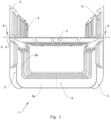
- This hull structure extends from bow to stern in a longitudinal X-X direction and comprises a monocoque plating, a platform, a main deck, a zerounolevel deck, weather decks which are extended for the entire longitudinal length of the ship, transverse bulkheads, one or more internal stiffening structures 1 and other structural elements.
- monocoque plating is a “single skin” monocoque plating (i.e., a “mono shell”) with a high thickness and without added reinforcements, such as longitudinal or transverse stiffening ribs, to ensure the necessary deformability of the solution.
- a high thickness of the monocoque plating means a monolithic laminate having a thickness ranging from 5 cm (for example, for the sides) to 20 cm or more (for example, for the bottom).
- the above-mentioned internal stiffening structures 1 include:
- Said one or more cradle-shaped load-bearing elements 5 extend in the above-mentioned longitudinal direction X-X between opposite head ends 5b.
- the above-mentioned cradle-shaped load-bearing elements 5 comprise:
- the above-mentioned one or more cradle-shaped load-bearing elements 5 are connected to the transverse bulkheads 3:
- the above-mentioned first portions of said transverse bulkheads 3 that are connected to the head ends 5B of the cradle-shaped load-bearing elements 5, compatibly with the design constraints, are spaced at least 30 cm, more preferably at least 50 cm, from the peripheral edge of said transverse bulkheads 3, that is to say from the point where said transverse bulkheads 3 are attached to the hull monocoque plating or to the decks.
- This allows to guarantee the flexibility of the structure and to minimize the transfer of loads to the internal components by means of an elastic hinged behavior of said transverse bulkheads (3).
- the above-mentioned transverse bulkheads 3 comprise respective stiffening ribs 4 extending axially in a prevalent vertical direction Z-Z. These stiffening ribs 4 therefore identify stiffening uprights for the transverse bulkheads (3).
- stiffening ribs 4 terminate with opposing flute-beak tapered head ends 4a, so as to:
- the above-mentioned uprights 4 also stop at a predetermined distance, preferably at least 10 cm, more preferably at least 20 cm, even more preferably at least 30 cm compatibly with the design constraints, from the peripheral edge of the transverse bulkheads 3.
- the above-mentioned perimeter frame of the transverse bulkheads 3 not affected by the stiffening ribs 4 has an increased thickness with respect to the remaining part of the bulkhead affected by the ribs, preferably an increased thickness of 15-35%, more preferably an increased thickness of 20-25%.
- the above-mentioned at least one deck 2 extends in the above-mentioned longitudinal direction X-X between opposite head ends starting from two respective, contiguous and opposite transverse bulkheads 3 so that said deck 2 is longitudinally in between the two above mentioned bulkheads 3.
- the above-mentioned at least one deck 2 extends in the longitudinal direction X-X for a portion having a longitudinal length corresponding to the longitudinal distance between the two opposing contiguous transverse bulkheads 3 between which said deck 2 extends.
- transverse portion S is identified that:
- transverse portion S extends for a vertical portion of said transverse bulkheads 3 that is greater than the portion coupled with the deck 2.
- transverse strip S being positioned over the respective contact area 6 in correspondence with said deck 2.
- the above-mentioned transverse strip S of the transverse bulkheads 3 without stiffening ribs has an increased thickness compared to the remaining part of the bulkhead affected by the ribs, preferably a thickness increased by 15-35%, more preferably a thickness increased by 20-25%.
- said transverse bulkheads 3, said at least one deck 2 and said cradle-shaped load-bearing elements 5 are made with said composite material based on suitably reinforced plastic material.
- transverse bulkheads 3 consist of transverse structural bulkheads, watertight or not, of the hull.
- the above-mentioned at least one deck 2 comprises longitudinal and/or transverse beams that terminate at a predetermined distance, preferably at least 10 cm, more preferably at least 20 cm, even more preferably at least 30 cm, from the bulkheads (if longitudinal) or from the monocoque plating (if transverse) with corresponding flute-beak tapered ends.
- the above-mentioned one or more cradle-shaped load-bearing elements 5 comprise a plurality of distinct and parallel elements in said transverse direction Y-Y.
- the hull structure according to the invention is intended to be used to constitute a ship wherein the cradle-shaped load-bearing elements 5 support various components, in particular, but not limited to, on-board machinery selected from the group comprising: engines, generators, tanks, machinery and/or other devices or other equipment required on board the ship while underway.
- on-board machinery selected from the group comprising: engines, generators, tanks, machinery and/or other devices or other equipment required on board the ship while underway.
- the above-mentioned machinery also includes other components to be used during the "research" phase for the search and destruction of mines.
- the hull structure according to the present invention allows to meet the above-mentioned need for shock resistance and at the same time to overcome the drawbacks referred to in the introductory part of the present description with reference to the known art.
- the presence of the cradle-shaped load-bearing elements 5 supported only through the transverse bulkheads allows for sufficiently elastic supports to absorb vibrations and noises generated by the use of engines and other on-board machinery.
- each bulkhead behaves like a membrane bound to the hull monocoque plating by means of an elastic hinge, thus allowing the vibrations generated by the above-mentioned materials supported by the cradle-shaped load-bearing elements to be absorbed with an effective elastic suspension.
- Another advantage of the hull structure according to the present invention lies in the possibility of making and conforming the various parts according to specific needs without excessive shape limits.
Landscapes
- Engineering & Computer Science (AREA)
- Chemical & Material Sciences (AREA)
- Combustion & Propulsion (AREA)
- Mechanical Engineering (AREA)
- Ocean & Marine Engineering (AREA)
- Vibration Prevention Devices (AREA)
- Wind Motors (AREA)
- Pharmaceuticals Containing Other Organic And Inorganic Compounds (AREA)
- Aviation & Aerospace Engineering (AREA)
- Containers Having Bodies Formed In One Piece (AREA)
- Moulding By Coating Moulds (AREA)
Claims (15)
- Structure de coque à base de matériau plastique renforcé de manière appropriée, dans laquelle ladite structure de coque s'étend de la proue à la poupe dans une direction longitudinale (X-X) et inclut un placage monocoque « simple peau » et une structure de raidissement interne (1), dans laquelle ladite structure de raidissement interne (1) comprend :- au moins un pont (2) ;- au moins deux cloisons transversales (3) opposées s'étendant verticalement et dans une direction transversale (Y-Y) orthogonale à ladite direction longitudinale (X-X) et audit au moins un pont (2) et- un ou plusieurs éléments porteurs en forme de berceau (5) pour soutenir des machines destinées à être logées sur ladite structure de coque, lesdits un ou plusieurs éléments porteurs en forme de berceau (5) s'étendant dans ladite direction longitudinale (X-X) entre des extrémités de tête (5b) opposées,caractérisée en ce que :- lesdits un ou plusieurs éléments porteurs en forme de berceau (5) sont soutenus uniquement auxdites extrémités de tête (5b) opposées desdits éléments porteurs en forme de berceau (5) et uniquement à partir de premières portions respectives desdites cloisons transversales (3) opposées et- ledit au moins un pont (2) s'étend dans ladite direction longitudinale (X-X) entre des extrémités opposées de têtes débutant à partir desdites deux cloisons transversales (3) opposées soutenant lesdits un ou plusieurs éléments porteurs en forme de berceau (5), ledit pont (2) étant longitudinalement entre lesdites cloisons transversales (3) opposées.
- Structure de coque selon la revendication 1, dans laquelle lesdites premières portions desdites cloisons transversales (3) opposées sont des portions internes espacées du bord périphérique desdites cloisons transversales (3), de préférence des premières portions espacées d'au moins 30 cm, plus préférentiellement d'au moins 50 cm du bord périphérique desdites cloisons transversales (3).
- Structure de coque selon la revendication 1 ou 2, dans laquelle lesdits éléments porteurs en forme de berceau (5) comprennent :- un corps (5a) s'étendant dans ladite direction longitudinale (X-X) entre lesdites au moins deux cloisons transversales (3) opposées et- des extrémités de tête (5b) opposées s'étendant dans ladite direction verticale (Z-Z) et reliées auxdites cloisons transversales (3).
- Structure de coque selon la revendication 1, 2 ou 3, dans laquelle lesdites cloisons transversales (3) comprennent des nervures de raidissement (4) s'étendant axialement dans une direction verticale (Z-Z) dominante, dans laquelle, de préférence, lesdites nervures de raidissement (4) se terminent par des extrémités effilées en bec de flûte opposées.
- Structure de coque selon la revendication 4, dans laquelle lesdites nervures de raidissement (4) s'arrêtent à une distance limitée prédéterminée, de préférence à au moins 10 cm, plus préférentiellement à au moins 20 cm, encore plus préférentiellement à au moins 30 cm, du bord périphérique desdites cloisons transversales (3), le long de la totalité du bord périphérique des cloisons transversales (3) susmentionnées, résultant en un cadre périmétrique sans nervures de raidissement (4).
- Structure de coque selon la revendication 5, dans laquelle ledit cadre périmétrique sans nervures de raidissement (4) possède une épaisseur accrue par rapport à la partie restante de la cloison où lesdites nervures de raidissement (4) sont situées, de préférence une épaisseur accrue de 15 à 35 %, plus préférentiellement une épaisseur accrue de 20 à 25 %.
- Structure de coque selon l'une quelconque des revendications 1 à 6, dans laquelle ledit au moins un pont (2) s'étend dans ladite direction longitudinale (X-X) sur une section ayant une longueur longitudinale correspondant à la distance longitudinale entre lesdites deux cloisons transversales (3) contiguës opposées entre lesquelles ledit pont (2) s'étend.
- Structure de coque selon l'une des revendications 1 à 7, dans laquelle :- ledit au moins un pont (2) est raccordé auxdites deux cloisons transversales (3) opposées en correspondance avec des zones de contact (6) respectives s'étendant dans ladite direction transversale (Y-Y) le long desdites cloisons transversales (3) et- dans chaque cloison transversale (3), une portion transversale (S) est identifiée, qui incorpore la zone de contact (6) concernée et est dépourvue de toute nervure de raidissement.
- Structure de coque selon la revendication 8 et la revendication 4 ou 5, dans laquelle, dans chaque cloison verticale (3), les nervures de raidissement (4) concernées s'arrêtent à une distance prédéfinie de ladite zone de contact (6), de sorte que, dans chaque cloison verticale (3), une bande transversale (S) sans nervures de raidissement (4) chevauchant la zone de contact (6) concernée en correspondance avec ledit pont (2) soit identifiée.
- Structure de coque selon la revendication 9, dans laquelle ladite bande transversale (S) desdites cloisons verticales (3) sans nervures de raidissement (4) possède une épaisseur accrue par rapport à la partie restante de la cloison où lesdites nervures de raidissement sont situées, de préférence une épaisseur accrue de 15 à 35 %, plus préférentiellement une épaisseur accrue de 20 à 25 %.
- Structure de coque selon l'une des revendications 1 à 10, dans laquelle ladite base en matériau plastique renforcé par des fibres de manière appropriée est un matériau composite thermodurcissable comprenant des fibres et/ou des charges de renfort.
- Structure de coque selon l'une des revendications 1 à 11, dans laquelle :- lesdites cloisons transversales (3) sont constituées de cloisons structurelles transversales, à la fois étanches à l'eau et autres, de la coque ;- lesdites cloisons transversales (3), ledit au moins un pont (2) et lesdits éléments porteurs en forme de berceau (5) sont constitués dudit matériau composite à base de matériau plastique renforcé par des fibres de manière appropriée et- ledit au moins un pont (2) comprend des raidisseurs longitudinaux et/ou transversaux, qui se terminent à une distance prédéterminée, de préférence à au moins 10 cm, plus préférentiellement à au moins 20 cm, encore plus préférentiellement à au moins 30 cm, des cloisons (s'ils sont longitudinaux) ou du placage (s'ils sont transversaux) par des extrémités effilées en bec de flûte correspondantes.
- Structure de coque selon l'une quelconque des revendications 1 à 12, dans laquelle lesdits un ou plusieurs éléments porteurs en forme de berceau (5) comprennent une pluralité d'éléments distincts et parallèles dans ladite direction transversale (Y-Y).
- Structure de coque selon l'une quelconque des revendications 1 à 13, comprenant plus de deux cloisons transversales (3) décalées les unes des autres dans ladite direction longitudinale (X-X), davantage de ponts (2) s'étendant entre lesdites cloisons transversales (3) et/ou davantage d'éléments porteurs en forme de berceau (5) s'étendant entre lesdites cloisons transversales (3) pour soutenir lesdites machines.
- Navire comprenant une structure de coque selon l'une quelconque des revendications 1 à 14, ledit navire comprenant des machines soutenues par lesdits éléments porteurs en forme de berceau (5), lesdites machines embarquées étant choisies dans le groupe comprenant : des moteurs, des générateurs et/ou d'autres dispositifs ou d'autres équipements requis à bord du navire pendant la navigation.
Priority Applications (2)
| Application Number | Priority Date | Filing Date | Title |
|---|---|---|---|
| MA58180A MA58180B1 (fr) | 2019-12-23 | 2020-12-22 | Structure de coque |
| HRP20250072TT HRP20250072T1 (hr) | 2019-12-23 | 2020-12-22 | Konstrukcija trupa |
Applications Claiming Priority (2)
| Application Number | Priority Date | Filing Date | Title |
|---|---|---|---|
| IT102019000025357A IT201900025357A1 (it) | 2019-12-23 | 2019-12-23 | Struttura di scafo |
| PCT/IB2020/062340 WO2021130674A1 (fr) | 2019-12-23 | 2020-12-22 | Structure de coque |
Publications (4)
| Publication Number | Publication Date |
|---|---|
| EP4081450A1 EP4081450A1 (fr) | 2022-11-02 |
| EP4081450B1 true EP4081450B1 (fr) | 2024-11-27 |
| EP4081450C0 EP4081450C0 (fr) | 2024-11-27 |
| EP4081450B8 EP4081450B8 (fr) | 2025-01-22 |
Family
ID=70228568
Family Applications (1)
| Application Number | Title | Priority Date | Filing Date |
|---|---|---|---|
| EP20842040.6A Active EP4081450B8 (fr) | 2019-12-23 | 2020-12-22 | Structure de coque |
Country Status (11)
| Country | Link |
|---|---|
| US (1) | US12497136B2 (fr) |
| EP (1) | EP4081450B8 (fr) |
| KR (1) | KR20220116544A (fr) |
| CN (1) | CN114845929A (fr) |
| AU (1) | AU2020415482A1 (fr) |
| ES (1) | ES3006910T3 (fr) |
| HR (1) | HRP20250072T1 (fr) |
| IT (1) | IT201900025357A1 (fr) |
| MA (1) | MA58180B1 (fr) |
| PL (1) | PL4081450T3 (fr) |
| WO (1) | WO2021130674A1 (fr) |
Cited By (1)
| Publication number | Priority date | Publication date | Assignee | Title |
|---|---|---|---|---|
| US20230039924A1 (en) * | 2019-12-23 | 2023-02-09 | Intermarine S.P.A. | Hull structure |
Families Citing this family (3)
| Publication number | Priority date | Publication date | Assignee | Title |
|---|---|---|---|---|
| CN113978608B (zh) * | 2021-11-09 | 2023-05-05 | 广州文冲船厂有限责任公司 | 一种船舶负角隅结构及船舶 |
| CN114313100B (zh) * | 2021-12-17 | 2022-09-30 | 中国人民解放军海军工程大学 | 振动局域化的耐压艇体的舱壁间距布置方法 |
| CN117360686A (zh) * | 2023-10-27 | 2024-01-09 | 上海船舶研究设计院 | 船舶主机顶撑加强结构 |
Family Cites Families (7)
| Publication number | Priority date | Publication date | Assignee | Title |
|---|---|---|---|---|
| IT1186843B (it) * | 1985-03-15 | 1987-12-16 | Intermarine Spa | Nave con scafo monoguscio di materiale composito a base di materia plastica |
| IT1261908B (it) * | 1993-10-13 | 1996-06-03 | Intermarine Spa | Struttura di scafo di materiale non metallico. |
| IT1293201B1 (it) * | 1997-04-09 | 1999-02-16 | Intermarine Spa | Struttura navale leggera. |
| ITPD20060259A1 (it) * | 2006-06-23 | 2007-12-24 | Fb Design Srl | Struttura di scafo inaffondabile e metodo per la sua realizzazione |
| AU2007200791A1 (en) * | 2007-02-22 | 2008-09-11 | Farallon Capital Pty Ltd | Boat construction method |
| CN107330894B (zh) * | 2017-06-22 | 2018-06-29 | 同济大学 | 面向平面舱壁类型船舱的点云数据自动分割方法 |
| IT201900025357A1 (it) * | 2019-12-23 | 2021-06-23 | Intermarine Spa | Struttura di scafo |
-
2019
- 2019-12-23 IT IT102019000025357A patent/IT201900025357A1/it unknown
-
2020
- 2020-12-22 WO PCT/IB2020/062340 patent/WO2021130674A1/fr not_active Ceased
- 2020-12-22 EP EP20842040.6A patent/EP4081450B8/fr active Active
- 2020-12-22 MA MA58180A patent/MA58180B1/fr unknown
- 2020-12-22 PL PL20842040.6T patent/PL4081450T3/pl unknown
- 2020-12-22 CN CN202080089470.3A patent/CN114845929A/zh active Pending
- 2020-12-22 ES ES20842040T patent/ES3006910T3/es active Active
- 2020-12-22 AU AU2020415482A patent/AU2020415482A1/en active Pending
- 2020-12-22 KR KR1020227025322A patent/KR20220116544A/ko active Pending
- 2020-12-22 US US17/788,065 patent/US12497136B2/en active Active
- 2020-12-22 HR HRP20250072TT patent/HRP20250072T1/hr unknown
Cited By (2)
| Publication number | Priority date | Publication date | Assignee | Title |
|---|---|---|---|---|
| US20230039924A1 (en) * | 2019-12-23 | 2023-02-09 | Intermarine S.P.A. | Hull structure |
| US12497136B2 (en) * | 2019-12-23 | 2025-12-16 | Intermine—S.p.A. | Hull structure |
Also Published As
| Publication number | Publication date |
|---|---|
| WO2021130674A1 (fr) | 2021-07-01 |
| ES3006910T3 (en) | 2025-03-19 |
| CN114845929A (zh) | 2022-08-02 |
| HRP20250072T1 (hr) | 2025-03-28 |
| AU2020415482A1 (en) | 2022-08-11 |
| EP4081450A1 (fr) | 2022-11-02 |
| IT201900025357A1 (it) | 2021-06-23 |
| EP4081450B8 (fr) | 2025-01-22 |
| KR20220116544A (ko) | 2022-08-23 |
| PL4081450T3 (pl) | 2025-04-14 |
| US20230039924A1 (en) | 2023-02-09 |
| EP4081450C0 (fr) | 2024-11-27 |
| US12497136B2 (en) | 2025-12-16 |
| MA58180B1 (fr) | 2025-01-31 |
Similar Documents
| Publication | Publication Date | Title |
|---|---|---|
| EP4081450B1 (fr) | Structure de coque | |
| US5899162A (en) | Tanker reconstruction | |
| Bertram et al. | Ship design for efficiency and economy | |
| US6357373B1 (en) | Rebuilt double hull vessel and method of rebuilding a single hull vessel into a double hull vessel | |
| US5582124A (en) | Hybrid framing system for vessels | |
| KR20180040887A (ko) | 컨테이너선 | |
| JP6952635B2 (ja) | 船舶 | |
| EP0194531B1 (fr) | Bateau monocoque fabriqué en matériaux composites à base de plastiques | |
| KR910004914B1 (ko) | 탱크커버 부착 액화가스 운반선 | |
| KR20160037257A (ko) | 부유식 해상구조물 선수부의 불워크 구조 | |
| FI79269C (fi) | Fartyg utan tvaerbalk. | |
| KR0176274B1 (ko) | 유조선의 이중 선각구조 | |
| KR20180100298A (ko) | 선박 | |
| EP0870673A1 (fr) | Structure légère de bateau | |
| KR20120044879A (ko) | 선박용 컨테이너 적재 구조물 | |
| SU1088982A1 (ru) | Бортова гофрированна обшивка корпуса судна | |
| JPH0782723A (ja) | 防舷材 | |
| JP7382237B2 (ja) | 船舶 | |
| KR101238088B1 (ko) | 선박의 강화 격벽 | |
| KR102456766B1 (ko) | 선박 | |
| RU2510923C2 (ru) | Безреберный обтекатель антенны гидроакустической станции | |
| Smith et al. | A survey of ship motion reduction devices | |
| KR102769445B1 (ko) | 선박의 빌지웰 배치구조 | |
| KR200224503Y1 (ko) | 컨테이너 선의 선체 구조 | |
| KR20020092079A (ko) | 선박의 Fore peak tank 구조 |
Legal Events
| Date | Code | Title | Description |
|---|---|---|---|
| REG | Reference to a national code |
Ref country code: HR Ref legal event code: TUEP Ref document number: P20250072T Country of ref document: HR |
|
| STAA | Information on the status of an ep patent application or granted ep patent |
Free format text: STATUS: UNKNOWN |
|
| STAA | Information on the status of an ep patent application or granted ep patent |
Free format text: STATUS: THE INTERNATIONAL PUBLICATION HAS BEEN MADE |
|
| PUAI | Public reference made under article 153(3) epc to a published international application that has entered the european phase |
Free format text: ORIGINAL CODE: 0009012 |
|
| STAA | Information on the status of an ep patent application or granted ep patent |
Free format text: STATUS: REQUEST FOR EXAMINATION WAS MADE |
|
| 17P | Request for examination filed |
Effective date: 20220719 |
|
| AK | Designated contracting states |
Kind code of ref document: A1 Designated state(s): AL AT BE BG CH CY CZ DE DK EE ES FI FR GB GR HR HU IE IS IT LI LT LU LV MC MK MT NL NO PL PT RO RS SE SI SK SM TR |
|
| DAX | Request for extension of the european patent (deleted) | ||
| RAV | Requested validation state of the european patent: fee paid |
Extension state: TN Effective date: 20220719 Extension state: MA Effective date: 20220719 |
|
| GRAP | Despatch of communication of intention to grant a patent |
Free format text: ORIGINAL CODE: EPIDOSNIGR1 |
|
| STAA | Information on the status of an ep patent application or granted ep patent |
Free format text: STATUS: GRANT OF PATENT IS INTENDED |
|
| INTG | Intention to grant announced |
Effective date: 20240814 |
|
| GRAS | Grant fee paid |
Free format text: ORIGINAL CODE: EPIDOSNIGR3 |
|
| GRAA | (expected) grant |
Free format text: ORIGINAL CODE: 0009210 |
|
| STAA | Information on the status of an ep patent application or granted ep patent |
Free format text: STATUS: THE PATENT HAS BEEN GRANTED |
|
| AK | Designated contracting states |
Kind code of ref document: B1 Designated state(s): AL AT BE BG CH CY CZ DE DK EE ES FI FR GB GR HR HU IE IS IT LI LT LU LV MC MK MT NL NO PL PT RO RS SE SI SK SM TR |
|
| REG | Reference to a national code |
Ref country code: GB Ref legal event code: FG4D |
|
| REG | Reference to a national code |
Ref country code: CH Ref legal event code: EP |
|
| GRAT | Correction requested after decision to grant or after decision to maintain patent in amended form |
Free format text: ORIGINAL CODE: EPIDOSNCDEC |
|
| REG | Reference to a national code |
Ref country code: IE Ref legal event code: FG4D |
|
| REG | Reference to a national code |
Ref country code: DE Ref legal event code: R096 Ref document number: 602020042207 Country of ref document: DE |
|
| REG | Reference to a national code |
Ref country code: CH Ref legal event code: PK Free format text: BERICHTIGUNG B8 |
|
| RAP4 | Party data changed (patent owner data changed or rights of a patent transferred) |
Owner name: INTERMARINE - S.P.A. |
|
| U01 | Request for unitary effect filed |
Effective date: 20241218 |
|
| REG | Reference to a national code |
Ref country code: MA Ref legal event code: VAGR Ref document number: 58180 Country of ref document: MA Kind code of ref document: B1 |
|
| U07 | Unitary effect registered |
Designated state(s): AT BE BG DE DK EE FI FR IT LT LU LV MT NL PT RO SE SI Effective date: 20250110 |
|
| U20 | Renewal fee for the european patent with unitary effect paid |
Year of fee payment: 5 Effective date: 20250130 |
|
| REG | Reference to a national code |
Ref country code: GR Ref legal event code: EP Ref document number: 20250400163 Country of ref document: GR Effective date: 20250211 |
|
| REG | Reference to a national code |
Ref country code: HR Ref legal event code: ODRP Ref document number: P20250072T Country of ref document: HR Payment date: 20250121 Year of fee payment: 5 |
|
| REG | Reference to a national code |
Ref country code: ES Ref legal event code: FG2A Ref document number: 3006910 Country of ref document: ES Kind code of ref document: T3 Effective date: 20250319 |
|
| REG | Reference to a national code |
Ref country code: HR Ref legal event code: T1PR Ref document number: P20250072 Country of ref document: HR |
|
| PG25 | Lapsed in a contracting state [announced via postgrant information from national office to epo] |
Ref country code: IS Free format text: LAPSE BECAUSE OF FAILURE TO SUBMIT A TRANSLATION OF THE DESCRIPTION OR TO PAY THE FEE WITHIN THE PRESCRIBED TIME-LIMIT Effective date: 20250327 |
|
| PG25 | Lapsed in a contracting state [announced via postgrant information from national office to epo] |
Ref country code: RS Free format text: LAPSE BECAUSE OF FAILURE TO SUBMIT A TRANSLATION OF THE DESCRIPTION OR TO PAY THE FEE WITHIN THE PRESCRIBED TIME-LIMIT Effective date: 20250227 |
|
| PG25 | Lapsed in a contracting state [announced via postgrant information from national office to epo] |
Ref country code: SM Free format text: LAPSE BECAUSE OF FAILURE TO SUBMIT A TRANSLATION OF THE DESCRIPTION OR TO PAY THE FEE WITHIN THE PRESCRIBED TIME-LIMIT Effective date: 20241127 |
|
| PG25 | Lapsed in a contracting state [announced via postgrant information from national office to epo] |
Ref country code: SK Free format text: LAPSE BECAUSE OF FAILURE TO SUBMIT A TRANSLATION OF THE DESCRIPTION OR TO PAY THE FEE WITHIN THE PRESCRIBED TIME-LIMIT Effective date: 20241127 |
|
| PG25 | Lapsed in a contracting state [announced via postgrant information from national office to epo] |
Ref country code: CZ Free format text: LAPSE BECAUSE OF FAILURE TO SUBMIT A TRANSLATION OF THE DESCRIPTION OR TO PAY THE FEE WITHIN THE PRESCRIBED TIME-LIMIT Effective date: 20241127 |
|
| REG | Reference to a national code |
Ref country code: CH Ref legal event code: PL |
|
| PG25 | Lapsed in a contracting state [announced via postgrant information from national office to epo] |
Ref country code: MC Free format text: LAPSE BECAUSE OF FAILURE TO SUBMIT A TRANSLATION OF THE DESCRIPTION OR TO PAY THE FEE WITHIN THE PRESCRIBED TIME-LIMIT Effective date: 20241127 |
|
| PLBE | No opposition filed within time limit |
Free format text: ORIGINAL CODE: 0009261 |
|
| STAA | Information on the status of an ep patent application or granted ep patent |
Free format text: STATUS: NO OPPOSITION FILED WITHIN TIME LIMIT |
|
| PG25 | Lapsed in a contracting state [announced via postgrant information from national office to epo] |
Ref country code: CH Free format text: LAPSE BECAUSE OF NON-PAYMENT OF DUE FEES Effective date: 20241231 |
|
| PG25 | Lapsed in a contracting state [announced via postgrant information from national office to epo] |
Ref country code: IE Free format text: LAPSE BECAUSE OF NON-PAYMENT OF DUE FEES Effective date: 20241222 |
|
| 26N | No opposition filed |
Effective date: 20250828 |
|
| VSFP | Annual fee paid to validation state [announced via postgrant information from national office to epo] |
Ref country code: MA Payment date: 20241224 Year of fee payment: 5 |
|
| PGFP | Annual fee paid to national office [announced via postgrant information from national office to epo] |
Ref country code: GB Payment date: 20251223 Year of fee payment: 6 |
|
| PGFP | Annual fee paid to national office [announced via postgrant information from national office to epo] |
Ref country code: NO Payment date: 20251218 Year of fee payment: 6 |
|
| PGFP | Annual fee paid to national office [announced via postgrant information from national office to epo] |
Ref country code: HR Payment date: 20251215 Year of fee payment: 6 |
|
| PGFP | Annual fee paid to national office [announced via postgrant information from national office to epo] |
Ref country code: TR Payment date: 20251211 Year of fee payment: 6 Ref country code: GR Payment date: 20251218 Year of fee payment: 6 |
|
| REG | Reference to a national code |
Ref country code: HR Ref legal event code: ODRP Ref document number: P20250072 Country of ref document: HR Payment date: 20251215 Year of fee payment: 6 |
|
| PGFP | Annual fee paid to national office [announced via postgrant information from national office to epo] |
Ref country code: PL Payment date: 20251211 Year of fee payment: 6 |
|
| U20 | Renewal fee for the european patent with unitary effect paid |
Year of fee payment: 6 Effective date: 20251223 |
|
| VSFP | Annual fee paid to validation state [announced via postgrant information from national office to epo] |
Ref country code: MA Payment date: 20251226 Year of fee payment: 6 |
|
| PGFP | Annual fee paid to national office [announced via postgrant information from national office to epo] |
Ref country code: ES Payment date: 20260122 Year of fee payment: 6 |