EP4082812B1 - Système de détection de pincement - Google Patents
Système de détection de pincement Download PDFInfo
- Publication number
- EP4082812B1 EP4082812B1 EP21171330.0A EP21171330A EP4082812B1 EP 4082812 B1 EP4082812 B1 EP 4082812B1 EP 21171330 A EP21171330 A EP 21171330A EP 4082812 B1 EP4082812 B1 EP 4082812B1
- Authority
- EP
- European Patent Office
- Prior art keywords
- pressure
- sensor device
- closure member
- sensitive sensor
- open
- Prior art date
- Legal status (The legal status is an assumption and is not a legal conclusion. Google has not performed a legal analysis and makes no representation as to the accuracy of the status listed.)
- Active
Links
Images



Classifications
-
- G—PHYSICS
- G01—MEASURING; TESTING
- G01N—INVESTIGATING OR ANALYSING MATERIALS BY DETERMINING THEIR CHEMICAL OR PHYSICAL PROPERTIES
- G01N3/00—Investigating strength properties of solid materials by application of mechanical stress
- G01N3/08—Investigating strength properties of solid materials by application of mechanical stress by applying steady tensile or compressive forces
-
- B—PERFORMING OPERATIONS; TRANSPORTING
- B60—VEHICLES IN GENERAL
- B60J—WINDOWS, WINDSCREENS, NON-FIXED ROOFS, DOORS, OR SIMILAR DEVICES FOR VEHICLES; REMOVABLE EXTERNAL PROTECTIVE COVERINGS SPECIALLY ADAPTED FOR VEHICLES
- B60J10/00—Sealing arrangements
- B60J10/80—Sealing arrangements specially adapted for opening panels, e.g. doors
- B60J10/82—Sealing arrangements specially adapted for opening panels, e.g. doors for movable panels in roofs
-
- B—PERFORMING OPERATIONS; TRANSPORTING
- B60—VEHICLES IN GENERAL
- B60J—WINDOWS, WINDSCREENS, NON-FIXED ROOFS, DOORS, OR SIMILAR DEVICES FOR VEHICLES; REMOVABLE EXTERNAL PROTECTIVE COVERINGS SPECIALLY ADAPTED FOR VEHICLES
- B60J7/00—Non-fixed roofs; Roofs with movable panels, e.g. rotary sunroofs
- B60J7/02—Non-fixed roofs; Roofs with movable panels, e.g. rotary sunroofs of sliding type, e.g. comprising guide shoes
- B60J7/04—Non-fixed roofs; Roofs with movable panels, e.g. rotary sunroofs of sliding type, e.g. comprising guide shoes with rigid plate-like element or elements, e.g. open roofs with harmonica-type folding rigid panels
-
- B—PERFORMING OPERATIONS; TRANSPORTING
- B60—VEHICLES IN GENERAL
- B60J—WINDOWS, WINDSCREENS, NON-FIXED ROOFS, DOORS, OR SIMILAR DEVICES FOR VEHICLES; REMOVABLE EXTERNAL PROTECTIVE COVERINGS SPECIALLY ADAPTED FOR VEHICLES
- B60J7/00—Non-fixed roofs; Roofs with movable panels, e.g. rotary sunroofs
- B60J7/02—Non-fixed roofs; Roofs with movable panels, e.g. rotary sunroofs of sliding type, e.g. comprising guide shoes
- B60J7/04—Non-fixed roofs; Roofs with movable panels, e.g. rotary sunroofs of sliding type, e.g. comprising guide shoes with rigid plate-like element or elements, e.g. open roofs with harmonica-type folding rigid panels
- B60J7/057—Driving or actuating arrangements e.g. manually operated levers or knobs
- B60J7/0573—Driving or actuating arrangements e.g. manually operated levers or knobs power driven arrangements, e.g. electrical
-
- E—FIXED CONSTRUCTIONS
- E05—LOCKS; KEYS; WINDOW OR DOOR FITTINGS; SAFES
- E05F—DEVICES FOR MOVING WINGS INTO OPEN OR CLOSED POSITION; CHECKS FOR WINGS; WING FITTINGS NOT OTHERWISE PROVIDED FOR, CONCERNED WITH THE FUNCTIONING OF THE WING
- E05F15/00—Power-operated mechanisms for wings
- E05F15/40—Safety devices, e.g. detection of obstructions or end positions
- E05F15/42—Detection using safety edges
- E05F15/44—Detection using safety edges responsive to changes in electrical conductivity
- E05F15/443—Detection using safety edges responsive to changes in electrical conductivity specially adapted for vehicle windows or roofs
-
- G—PHYSICS
- G01—MEASURING; TESTING
- G01L—MEASURING FORCE, STRESS, TORQUE, WORK, MECHANICAL POWER, MECHANICAL EFFICIENCY, OR FLUID PRESSURE
- G01L1/00—Measuring force or stress, in general
- G01L1/14—Measuring force or stress, in general by measuring variations in capacitance or inductance of electrical elements, e.g. by measuring variations of frequency of electrical oscillators
-
- E—FIXED CONSTRUCTIONS
- E05—LOCKS; KEYS; WINDOW OR DOOR FITTINGS; SAFES
- E05Y—INDEXING SCHEME ASSOCIATED WITH SUBCLASSES E05D AND E05F, RELATING TO CONSTRUCTION ELEMENTS, ELECTRIC CONTROL, POWER SUPPLY, POWER SIGNAL OR TRANSMISSION, USER INTERFACES, MOUNTING OR COUPLING, DETAILS, ACCESSORIES, AUXILIARY OPERATIONS NOT OTHERWISE PROVIDED FOR, APPLICATION THEREOF
- E05Y2900/00—Application of doors, windows, wings or fittings thereof
- E05Y2900/50—Application of doors, windows, wings or fittings thereof for vehicles
- E05Y2900/53—Type of wing
- E05Y2900/542—Roof panels
-
- G—PHYSICS
- G01—MEASURING; TESTING
- G01N—INVESTIGATING OR ANALYSING MATERIALS BY DETERMINING THEIR CHEMICAL OR PHYSICAL PROPERTIES
- G01N2203/00—Investigating strength properties of solid materials by application of mechanical stress
- G01N2203/0001—Type of application of the stress
- G01N2203/0003—Steady
-
- G—PHYSICS
- G01—MEASURING; TESTING
- G01N—INVESTIGATING OR ANALYSING MATERIALS BY DETERMINING THEIR CHEMICAL OR PHYSICAL PROPERTIES
- G01N2203/00—Investigating strength properties of solid materials by application of mechanical stress
- G01N2203/0014—Type of force applied
- G01N2203/0016—Tensile or compressive
- G01N2203/0019—Compressive
-
- G—PHYSICS
- G01—MEASURING; TESTING
- G01N—INVESTIGATING OR ANALYSING MATERIALS BY DETERMINING THEIR CHEMICAL OR PHYSICAL PROPERTIES
- G01N2203/00—Investigating strength properties of solid materials by application of mechanical stress
- G01N2203/0058—Kind of property studied
- G01N2203/0069—Fatigue, creep, strain-stress relations or elastic constants
- G01N2203/0075—Strain-stress relations or elastic constants
-
- G—PHYSICS
- G01—MEASURING; TESTING
- G01N—INVESTIGATING OR ANALYSING MATERIALS BY DETERMINING THEIR CHEMICAL OR PHYSICAL PROPERTIES
- G01N2203/00—Investigating strength properties of solid materials by application of mechanical stress
- G01N2203/02—Details not specific for a particular testing method
- G01N2203/06—Indicating or recording means; Sensing means
- G01N2203/0617—Electrical or magnetic indicating, recording or sensing means
-
- G—PHYSICS
- G01—MEASURING; TESTING
- G01N—INVESTIGATING OR ANALYSING MATERIALS BY DETERMINING THEIR CHEMICAL OR PHYSICAL PROPERTIES
- G01N2203/00—Investigating strength properties of solid materials by application of mechanical stress
- G01N2203/02—Details not specific for a particular testing method
- G01N2203/06—Indicating or recording means; Sensing means
- G01N2203/067—Parameter measured for estimating the property
- G01N2203/0676—Force, weight, load, energy, speed or acceleration
-
- G—PHYSICS
- G01—MEASURING; TESTING
- G01N—INVESTIGATING OR ANALYSING MATERIALS BY DETERMINING THEIR CHEMICAL OR PHYSICAL PROPERTIES
- G01N2203/00—Investigating strength properties of solid materials by application of mechanical stress
- G01N2203/02—Details not specific for a particular testing method
- G01N2203/06—Indicating or recording means; Sensing means
- G01N2203/067—Parameter measured for estimating the property
- G01N2203/0682—Spatial dimension, e.g. length, area, angle
Definitions
- the invention relates to a pinch detection system for detecting a pinch of an object between a moveably arranged closure member of an open-roof assembly and an edge of a roof opening. Further, the invention relates to a corresponding method of detecting a pinch.
- the open-roof assembly is well-known.
- the open-roof assembly is configured to be mounted in a vehicle roof and comprises at least one moveably arranged closure member.
- the closure member is configured and arranged to cover an opening in the vehicle roof or at least partly uncover the opening in the vehicle roof.
- the closure member is a transparent panel and comprises glass or a suitable plastics.
- the closure member may be configured to tilt or to slide.
- a foreign object may become trapped between an edge of the opening in the vehicle roof and the moving closure member.
- a pinch detection system is intended to detect a pinch with a foreign object as soon as possible and to reverse a movement to ensure safe release of the foreign object.
- a pinch needs to be detected as soon as possible such that a force exerted on the foreign object is kept as small as possible. Further, legal requirements applicable in certain jurisdictions limit the maximum force under specified conditions.
- pinch detection system One of the known kinds of pinch detection systems is an indirect system, wherein a property of the open-roof system is detected, when the closure member is moving. The detected property is immediately analysed and an unexpected value of the property may be used to determine that a pinch has occurred.
- a pinch detection system needs to be able to detect a pinch with any foreign object irrespective of properties of the foreign object.
- Indirect pinch detection systems need to designed with different kind of properties of foreign objects in mind.
- a stiffness or compression rate of the object needs to be considered. The stiffer the object, i.e. the higher the compression rate of the object, the faster an exerted force increases with displacement of the closure member.
- the stiffness or compression rate may be represented with a spring rate expressed in N/mm. With a soft object having a relatively small spring rate, e.g. a spring rate of about 10 or about 20 N/mm, the closure member may move over a small distance before a maximum pinch force of e.g.
- a pinch detection system comprises a direct detection.
- a pressure sensitive sensor is provided along an edge of the moveably arranged closure member or along an edge of the roof opening.
- the known pressure sensitive sensor functions like a switch, wherein upon application of sufficient pressure, two electrodes are brought into electrical contact.
- a capacitive measurement is performed.
- an approaching object may be detected when it is nearby, but not yet touching.
- the known direct pinch detection systems are relatively simple in the sense that they only provide an output indicating that a pinch occurred or is about to occur.
- the sensor adds costs to the open-roof assembly for pinch detection.
- such pinch detection system does not add functionality or any improved user experience. Therefore, such costs are commercially not feasible and, as a result, the known direct pinch detection systems are commonly omitted and the indirect pinch detection systems are used instead.
- reliable detection of a pinch with a hard object may be challenging for an indirect pinch detection system and a direct pinch detection system may sometimes be preferred over an indirect pinch detection system.
- DE4201019A1 discloses an 'accident preventing arrangement for a panel moved by switchable drive'.
- the object is achieved in an open-roof assembly for covering or at least partly uncovering an opening in a vehicle roof according to claim 1.
- the pressure-sensitive sensor device is configured to detect a location of the exerted pressure along its length. Thus, more information is obtained when an object touches the pressure-sensitive device. Such additional information may be used to provide further functionality other than for merely detecting a pinch as described in more detail hereinafter in the description of certain embodiments.
- the pressure-sensitive sensor device may be technically provided by one or more of a number of embodiments employing generally known methods and techniques. For example, a number of individually pressure-sensitive switches may be arranged in an elongated array or a number of capacitive sensors may be applied.
- the pressure-sensitive sensor device is configured to detect a local deformation due to the local pressure exerted on the pressure-sensitive sensor device.
- a local pressure is detected, including the location and a local deformation, which may provide information regarding shape or size of an object exerting the pressure.
- a sensor detecting a local deformation employs capacitive sensing.
- An example of such a sensor is disclosed in US2020124397 .
- the disclosed sensor comprises a reference strip and a sliding strip, separated from each other by a spacer. Electrodes are located on the reference strip and the sliding strip. Bending of the sensor results in shifting of the sliding strip with respect to the reference strip. Measurements obtained from the electrodes show such shifting. Due to the presence of multiple electrodes, a location of the exerted pressure is detectable and a local deformation can be derived from the measurements.
- an open-roof assembly for covering or at least partly uncovering an opening in a vehicle roof, the open-roof assembly comprising a frame defining the opening, a moveably arranged closure member and a pressure-sensitive sensor device.
- the open-roof assembly comprises a closed state, in which the closure member covers the opening (3a) in the vehicle roof, and an open state, in which the closure member uncovers the roof opening (3a) at least partly.
- the pressure-sensitive sensor device is arranged between the closure member and the frame for detecting presence of an object between the closure member and the frame, at least when the closure member is moving from the open state towards the closed state.
- the pressure-sensitive sensor device further extends over a sensor device length and is configured to detect a location of a local pressure, which local pressure is exerted locally on the pressure-sensitive sensor device, along the sensor device length.
- the pressure-sensitive sensor device is moreover configured to detect a local deformation due to the local pressure exerted on the pressure-sensitive sensor device (40).
- the closure member is tiltably arranged and the pressure-sensitive sensor device, which is configured for detecting a local deformation, is arranged and configured to detect a hinge angle between the frame and the closure member.
- the pressure-sensitive device may be arranged extending between the frame and the closure member such that the pressure-sensitive sensor device forms a substantially right angle, which is detectable by the pressure-sensitive sensor.
- a part of the pressure-sensitive sensor device coupled to the closure member is moved away from the frame, due to which the pressure-sensitive sensor device no longer forms a right angle, but an obtuse angle.
- the change in angle is detectable by the pressure-sensitive sensor device.
- a tilt angle between the frame and the closure member may be derived from the change in angle of the pressure-sensitive sensor device.
- a pressure sensitive sensor device for detecting a pinched or trapped object is advantageously further used for detecting a tilt angle of the closure member, thereby enabling to omit or simplify any other position detection system, which improves a cost-effectiveness of the pressure-sensitive sensor device.
- the pressure-sensitive sensor device is integrated with a compressable seal arranged along a perimeter of the opening in the frame.
- a compressible compressable seal may be provided along a perimeter of the opening in the frame, for example for reducing noise when the open-roof assembly is in the closed state.
- the pressure-sensitive sensor device may be arranged in a compartment of the compressable seal, may be arranged on a surface of the compressable seal or may be integrated in the compressable seal. While, in this embodiment, the pressure-sensitive sensor device is arranged on the frame, in another embodiment, the pressure-sensitive sensor device may be arranged on the closure member.
- the pressure-sensitive sensor device is configured to detect a position of the moveably arranged closure member.
- a tilt angle may be detected, or a pressure may be exerted on the pressure-sensitive sensor device when the open-roof assembly is in the open state.
- a protruding element e.g. a roller on an extending arm, may be configured to push on the pressure-sensitive sensor device when the closure member is in its position of the open state.
- the closure member is slidably arranged and wherein the closure member exerts locally a pressure on the pressure-sensitive sensor device, when the open-roof assembly is in the open state.
- the closure member is first tilted and then slides. After the tilting movement, an edge of the closure member may still be at a level of the pressure-sensitive sensor device and may thus locally push the pressure-sensitive sensor device, while the closure member slides.
- another position detection system may be omitted or simplified.
- the pressure-sensitive sensor device is arranged such that an occupant of the vehicle is enabled to touch the pressure-sensitive sensor device in at least one of the closed state and the open state for operating at least one function of the open-roof assembly.
- a human-machine interface may be provided. Detecting the touch of an object like a human finger, or the like, at a specific location along the sensor length may be interpreted as a command, for example to open or to close the closure member.
- the pressure-sensitive sensor device may need to be arranged such that pressure may be exerted even when the closure member is arranged in contact with or close to the pressure-sensitive sensor device.
- the open-roof assembly further comprises a control unit, the control unit being configured to control the open-roof assembly in accordance with an operating parameter and being configured to execute an indirect pinch detection, wherein the control unit is configured to adapt the operating parameter upon detection of a locally exerted pressure on the pressure-sensitive sensor device.
- the pressure-sensitive sensor device may be used for preventing a pinch or entrapment, a further pinch detection system may be present as well.
- an indirect detection method may be present.
- the operating parameter may be a speed of the closure member during a closing movement, i.e. when moving from the open state towards the closed state.
- the operating parameter may relate to the indirect pinch detection system.
- the indirect detection system may comprise a threshold that is configured relatively high to prevent accidental incorrect pinch detection. When pressure is exerted on the pressure-sensitive sensor device, the threshold may be lowered in order to timely detect an actual pinch situation.
- Fig. 1A illustrates a vehicle roof 1 having an open roof assembly arranged therein.
- the open roof assembly comprises a moveable panel 2a and a fixed panel 2b.
- the moveable panel 2a is also referred to as a closure member, since the moveable panel 2a is moveable over a first roof opening 3a such to enable to open and to close the first roof opening 3a.
- a wind deflector 4 is arranged at a front side of the first roof opening 3a.
- the moveable panel 2a may be in a closed position, which is a position wherein the moveable panel 2a is arranged over and closes the first roof opening 3a and thus usually is arranged in a plane of the vehicle roof 1. Further, the moveable panel 2a may be in a tilted position, which is a position wherein a rear end RE of the moveable panel 2a is raised as compared to the closed position, while a front end FE of the moveable panel 2a is still in the closed position. Further, the moveable panel 2a may be in an open position, which is a position wherein the moveable panel 2a is slid open and the first roof opening 3a is partly or completely exposed.
- the illustrated vehicle roof 1 corresponds to a passenger car.
- the present invention is however not limited to passenger cars. Any other kind of vehicles that may be provided with a moveable panel are contemplated as well.
- Fig. 1B illustrates the same vehicle roof as shown in Fig. 1A having panels 2a and 2b.
- Fig. 1A shows the open roof assembly in the open position
- Fig. 1B is an exploded view of the open roof assembly in a closed position. Further, in this exploded view of Fig. 1B , it is shown that there is a second roof opening 3b.
- the first and second roof openings 3a, 3b are provided in a frame 5 of the open roof assembly. An edge 5a of the frame 5 defines the first roof opening 3a.
- the second roof opening 3b is arranged under the fixed panel 2b such that light may enter a vehicle interior passenger compartment through the fixed panel 2b, presuming that the fixed panel 2b is a glass panel or a similarly transparent panel, for example made of a plastic material or any other suitable material.
- the second roof opening 3b with a transparent or translucent fixed panel 2b is optional and may be omitted in another embodiment of the open roof assembly.
- the wind deflector 4 is commonly a flexible material, e.g. a woven or non-woven cloth having through holes arranged therein or a web or net.
- the flexible material is supported by a support structure 4a, e.g. a bar-like or tube-like structure, which structure is hingedly coupled, directly or indirectly, to the frame 5 at a hinge 4b.
- the wind deflector 4 is arranged in front of the first roof opening 3a and adapts air flow when the moveable panel 2a is in the open position. In its raised position, the wind deflector 4 reduces inconvenient noise due to air flow during driving. When the moveable panel 2a is in the closed position or in the tilted position, the wind deflector 4 is held down below the front end FE of the moveable panel 2a.
- the wind deflector 4 is raised by a spring force when the moveable panel 2a slides to an open position and the wind deflector 4 is pushed down by the moveable panel 2a when the moveable panel 2a slides back into its closed position.
- the moveable panel 2a is shown in an open position and the wind deflector 4 is shown in a raised position.
- Fig. 1B the moveable panel 2a is shown in a closed position and the wind deflector 4 is correspondingly shown in a position in which it is held down.
- Fig. 1B further illustrates a drive assembly having a first guide assembly 6a, a second guide assembly 6b, a first drive cable 7 and a second drive cable 8.
- the first and second guide assemblies 6a, 6b are arranged on respective side ends SE of the moveable panel 2a and may each comprise a guide and a mechanism.
- the guide is coupled to the frame 5, while the mechanism comprises moveable parts and is slideably moveable in the guide.
- the first and the second drive cables 7, 8 are provided between the mechanisms of the respective guide assemblies 6a, 6b and a electric motor 9.
- the drive cables 7, 8 couple the electric motor 9 to the mechanisms of the respective guide assemblies 6a, 6b such that upon operating the electric motor 9, the mechanisms start to move.
- a core of the drive cable 7, 8 is moved by the electric motor 9 such to push or pull on the mechanisms of the respective guides 6a, 6b.
- a drive assembly is well known in the art and is therefore not further elucidated herein.
- any other suitable drive assembly may be employed as well without departing from the scope of the present invention.
- an electric motor may be operatively arranged between the respective guides and the respective mechanisms of the guide assemblies 6a, 6b and, in such embodiment, a drive assembly may be omitted completely.
- the guide assemblies 6a, 6b may start movement with raising the rear end RE of the moveable panel 2a, thereby bringing the moveable panel 2a in the tilted position. Then, from the tilted position, the guide assemblies 6a, 6b may start to slide to bring the moveable panel 2a in the open position.
- the moveable panel 2a may be moveable to a tilted position by raising the rear end RE, while an open position is reached by first lowering the rear end RE and then sliding the moveable panel 2a under the fixed panel 2b or any other structure or element provided behind the rear end RE of the moveable panel 2a.
- the moveable panel 2a may be merely moveable between a closed position and a tilted position or between a closed position and an open position.
- the electric motor 9 is mounted near or below the front end FE of the moveable panel 2a at a recess 10. In another embodiment, the electric motor 9 may be positioned at any other suitable position or location. For example, the electric motor 9 may be arranged near or below the rear end RE of the moveable panel 2a or below the fixed panel 2b.
- a control module 11 is schematically illustrated and is operatively coupled to the electric motor 9.
- the control module 11 may be any kind of processing module, either a software controlled processing module or a dedicated processing module, like an ASIC, which are both well known to those skilled in the art.
- the control module 11 may be a stand-alone control module or it may be operatively connected to another control module, like a multipurpose, generic vehicle control module.
- the control module 11 may be embedded in or be part of such a generic vehicle control module.
- the control module 11 may be embodied by any control module suitable for, capable of and configured for performing operation of the electric motor 9 and thus the moveable roof assembly.
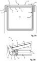
- Fig. 2A shows an open-roof assembly 20 in the open state.
- the open-roof assembly comprises the frame 5, in which the opening 3a is provided, and the moveably arranged closure member 2a is slid away to uncover the opening 3a.
- the closure member 2a is supported on the frame 5 by a suitable guide assembly comprising a stationary element 61 mounted on the frame 5 and a movable element 62, slidably supported by the stationary element 61.
- the movable element 62 is mounted on the closure member 2a such that the closure member 2a is slidably mounted.
- the moveable element 62 and closure member 2a are tiltable for lifting the closure member 2a out of a plane of the vehicle roof, when moving from the closed state to the open state, as above described in relation to Figs. 1A and 1B .
- the frame 5 comprises a frame edge 5a forming a perimeter of the opening 3a.
- a compressable seal 30 is arranged around the perimeter, close to the frame edge 5a.
- FIG. 2B A cross-section of the open-roof assembly 20 of Fig. 2A along line II-II is shown in Fig. 2B .
- the open-roof assembly 20 is illustrated in the closed state.
- the closure member 2a In the closed state, the closure member 2a is in contact with the compressable seal 30.
- the compressable seal 30 removes the guide assembly from view from a passenger compartment and reduces noise entering the passenger compartment of the vehicle.
- the compressable seal 30 is provided with a pressure-sensitive sensor device 40 arranged in an internal channel 31 of the compressable seal 30.
- the pressure-sensitive sensor device 40 is embodied as a strip-shaped sensor comprising a reference strip and a sliding strip, separated from each other by a spacer.
- the reference strip and the sliding strip have electrodes located thereon. Bending of the sensor results in shifting of the sliding strip with respect to the reference strip and thus shifting of the electrodes relative to each other. Measurements obtained from the electrodes show such shifting. Due to the presence of multiple electrodes, a location of the exerted pressure is detectable and a local deformation can be derived from the measurements.
- a sensor is described in more detail in US2020124397 , for example.
- another kind of sensor device may be applied equally well.
- a capacitive measurement or contact detection (e.g. a switch) based sensor device may be used, wherein such sensor device is configured to detect locally applied pressure and to detect the location of the applied pressure.
- the pressure-sensitive sensor device 40 is thus arranged between the closure member 2a and the frame 5 for detecting presence of an object between the closure member 2a and the frame 5.
- a control unit cf. control unit 11 of Fig. 1b ; not shown in Figs. 2A and 2B .
- the control unit may be configured to respond to such detection signal by controlling a movement of the closure member 2a, such as stopping a movement, reversing a movement, starting a movement, changing a speed of movement, and the like.
- the control unit may perform other operations as well in response to the detection signal.
- Figs. 3A and 3B illustrate a second embodiment of an open-roof assembly 20, wherein the closure member 2a (not shown in Fig. 3A for clarity) is tiltably (hingably) mounted.
- a stationary element 61 of a guide assembly is mounted on the frame 5 and a moveable element 62 is coupled to the stationary element 61 through a hinge 63.
- the moveable element 62 comprises a protruding arm 621, which extends over the compressable seal 30.
- the closure member 2a is attached to the moveable element 62 such that the closure member 2a may rotate around the hinge 63.
- a first pressure-sensitive sensor device 401 is integrated in the compressable seal 30 at a position of the front end (FE) of the closure member 2a.
- a second pressure-sensitive sensor device 402 is arranged on top of a large part of the remainder of the compressable seal 30. Further, each end of the second pressure-sensitive sensor device 402 is attached to the protruding arm 621 of the moveable element 62. At least the second pressure-sensitive device 402 is configured to detect a deformation such that the second pressure-sensitive device 402 is configured to detect an angle 41 between the protruding arm 621 and an upper surface of the compressable seal 30.
- the angle 41 corresponds to a substantially right angle. In the open state, the angle 41 will be become an acute angle.
- the detected angle 41 may be used by a control unit to control the operation of the opening and closing of the closure member 2a, wherein the detected angle 41 represents a position of the closure member 2a.
- the pressure-sensitive sensor device 402 configured to detect a deformation may be used solely for detecting a position of the moveable closure member 2a, in which case the pressure-sensitive sensor device 402 may be embodied as a short strip extending between the compressable seal 30 (or any other element stationarily attached to or part of the frame 5) and the closure member 2a. Further, there may be provided one such a short strip or two, one at each hinge 63.
- the pressure-sensitive sensor device 40 and the first and second pressure-sensitive sensor devices 401, 402 extend completely around the perimeter of the opening 3a. In another embodiment, only relevant parts of the perimeter may be provided with such a pressure-sensitive sensor device.
- Fig. 4 illustrates an embodiment of an open-roof assembly 20, wherein the closure member 2a is slidably arranged.
- the pressure-sensitive sensor device 40 is shown to be arranged in the compressable seal 30, but may as well be arranged on the compressable seal 30 or may be arranged on or in any other element stationary mounted on the frame 5.
- the closure member 2a or an element attached to the closure member 2a slides along the pressure-sensitive sensor device 40 such that the pressure-sensitive sensor device 40 detects a local pressure 80 that moves with the sliding movement of the closure member 2a.
- a tip end of the closure member 2a slides over the compressable seal 30, thereby exerting the local pressure 80 on the pressure-sensitive sensor device 40.
- a protruding element may be mounted on the closure member 2a, wherein the protruding element exerts the local pressure 80 on the pressure-sensitive sensor device 40.
- a rotatable element e.g. a roller or wheel, may be mounted on the closure member 2a such that the rotatable element rolls over the compressable seal 30, thereby reducing wear of the compressable seal 30 as compared to an element sliding over the compressable seal 30.
- Detection of the position in accordance with the embodiment of Fig. 4 may be used as a feedback to a control unit controlling a movement of the closure member 2a.
- Other parts or elements known from the prior art for detecting a position or a speed of movement may, optionally, be omitted in such embodiment.
- Fig. 5 shows an embodiment similar to the embodiment of Figs. 2A and 2B . Further, an anti-trap zone 70 is shown and arrow 71 indicates a closing movement direction. In the closing movement direction the closure member 2a moves from the open position towards the closed position.
- FIG. 5 a number of object touches are indicated, wherein an object touch corresponds to a local pressure exerted by an object on the pressure-sensitive sensor device integrated or embedded in the compressable seal 30.
- a first object touch 81 is indicated just in front of the closure member 2a, wherein it is assumed that the closure member 2a is moving in the closing movement direction 71.
- the first object touch 81 is outside the anti-trap zone and may therefore be regarded as not immediately leading to an entrapment.
- the closure member 2a may move further in the closing movement direction 71.
- a speed of the movement of the closure member 2a may be reduced, a visible or audible warning signal may be provided, or the like.
- it may be regarded a control signal from a user indicating that the closure member should stop and stay in its position.
- a second object touch comprises two simultaneous second object touches 82a, 82b, e.g. two fingers tapping on the compressable seal 30, exerting pressure on the pressure-sensitive sensor device.
- Such a simultaneous dual object touch 82a, 82b may be recognized as a user command.
- a control unit (not shown in Fig. 5 ) any specific command may be linked to such a user command, even in dependence of a position of the closure member 2a, for example.
- In a closed state it may be interpreted as a user command for opening; in the open state, it may be interpreted as a user command for closing. Further, if the closure member 2a is moving, it may be interpreted as a user command for stopping such movement.
- the front edge (FE) of the closure member 2a may be regarded as a potential entrapment and the closure member 2a may be stopped and possibly reversed to a full open state or to an open state at a position where the front edge (FE) is just outside the anti-trap zone 70, for example.
- a third object touch 83 is in the anti-trap zone 70.
- the closure member 2a may be controlled to change its state.
- the third object touch 83 may affect an anti-trap system or anti-pinch system that is based on an indirect detection. For example, based on an electrical current consumption of a motor driving the closure member 2a in relation to a position or speed of the closure member 2a, it may be determined that a movement of the closure member 2a is obstructed.
- Such an indirect detection system commonly uses a predetermined threshold such that, as soon as a particular parameter exceeds such threshold, a potential pinch is detected.
- the threshold is usually relatively high to prevent accidental, incorrect pinch detection, which may result in potentially relatively late detection, resulting in potentially relatively high forces exerted by the closure member 2a on the pinched object. If the third object touch 83 is detected in the anti-trap zone 70, the threshold may be lowered to detect an actual pinch sooner, thereby reducing a force exerted by the closure member 2a. Additionally or alternatively, a speed of the closure member 2a may be reduced. Further, an audible or visible warning signal may be provided.
- a fourth object touch 84 is at a position below the closure member 2a. Entrapment of an object is not expected at such position of the fourth object touch 84. Therefore, the fourth object touch 84 may be interpreted as a user command and in a control unit one or more commands may be linked to such fourth object touch 84, e.g. depending on actual conditions, like a state of the closure member 2a, daylight or night-time conditions for operating a lighting device or a sunblind device, or any other command as apparent to those skilled in the art.
- structural elements may be generated by application of three-dimensional (3D) printing techniques. Therefore, any reference to a structural element is intended to encompass any computer executable instructions that instruct a computer to generate such a structural element by three-dimensional printing techniques or similar computer controlled manufacturing techniques. Furthermore, any such reference to a structural element is also intended to encompass a computer readable medium carrying such computer executable instructions.
- the terms and phrases used herein are not intended to be limiting, but rather to provide an understandable description of the invention.
- the terms "a” or “an”, as used herein, are defined as one or more than one.
- the term plurality, as used herein, is defined as two or more than two.
- the term another, as used herein, is defined as at least a second or more.
- the terms including and/or having, as used herein, are defined as comprising (i.e., open language).
- the term coupled, as used herein, is defined as connected, although not necessarily directly.
Landscapes
- Engineering & Computer Science (AREA)
- Mechanical Engineering (AREA)
- Physics & Mathematics (AREA)
- General Physics & Mathematics (AREA)
- Health & Medical Sciences (AREA)
- Life Sciences & Earth Sciences (AREA)
- Chemical & Material Sciences (AREA)
- Analytical Chemistry (AREA)
- Biochemistry (AREA)
- General Health & Medical Sciences (AREA)
- Immunology (AREA)
- Pathology (AREA)
- Power-Operated Mechanisms For Wings (AREA)
Claims (6)
- Ensemble toit ouvrant pour couvrir ou découvrir au moins partiellement une ouverture (3a) dans un toit de véhicule, l'ensemble toit ouvrant comprenant un cadre (5) définissant l'ouverture, un élément de fermeture (2a) agencé de manière mobile et un dispositif capteur sensible à la pression (40),dans lequel l'ensemble toit ouvrant comprend un état fermé, dans lequel l'élément de fermeture couvre l'ouverture (3a) dans le toit de véhicule, et un état ouvert, dans lequel l'élément de fermeture découvre l'ouverture de toit (3a) au moins partiellement,dans lequel le dispositif capteur sensible à la pression (40) est agencé entre l'élément de fermeture (2a) et le cadre (5) pour détecter la présence d'un objet entre l'élément de fermeture (2a) et le cadre (5), au moins lorsque l'élément de fermeture (2a) transite de l'état ouvert vers l'état fermé, etdans lequel le dispositif capteur sensible à la pression (40) s'étend sur une longueur de dispositif capteur et est configuré pour détecter un emplacement d'une pression locale, laquelle pression locale est exercée localement sur le dispositif capteur sensible à la pression (40), le long de la longueur de dispositif capteur,dans lequel le dispositif capteur sensible à la pression (40) est configuré pour détecter une position de l'élément de fermeture (2a) agencé de manière mobile, etl'élément de fermeture (2a) est agencé de manière coulissante et dans lequel l'élément de fermeture (2a) exerce localement une pression sur le dispositif capteur sensible à la pression (40), lorsque l'ensemble toit ouvrant est dans l'état ouvert,caractérisé en ce quel'élément de fermeture (2a) est configuré pour coulisser le long du dispositif capteur sensible à la pression (40) pour que le dispositif capteur sensible à la pression (40) détecte la position de la pression locale exercée par l'élément de fermeture (2a), qui se déplace conjointement avec le mouvement de coulissement de l'élément de fermeture (2a).
- Ensemble toit ouvrant selon la revendication 1, dans lequel le dispositif capteur sensible à la pression (40) est configuré pour détecter une déformation locale due à la pression locale exercée sur le dispositif capteur sensible à la pression (40).
- Ensemble toit ouvrant pour couvrir ou découvrir au moins partiellement une ouverture (3a) dans un toit de véhicule, l'ensemble toit ouvrant comprenant un cadre (5) définissant l'ouverture, un élément de fermeture (2a) agencé de manière mobile et un dispositif capteur sensible à la pression (40),dans lequel l'ensemble toit ouvrant comprend un état fermé, dans lequel l'élément de fermeture couvre l'ouverture (3a) dans le toit de véhicule, et un état ouvert, dans lequel l'élément de fermeture découvre l'ouverture de toit (3a) au moins partiellement,dans lequel le dispositif capteur sensible à la pression (40) est agencé entre l'élément de fermeture (2a) et le cadre (5) pour détecter la présence d'un objet entre l'élément de fermeture (2a) et le cadre (5), au moins lorsque l'élément de fermeture (2a) transite de l'état ouvert vers l'état fermé, etdans lequel le dispositif capteur sensible à la pression (40) s'étend sur une longueur de dispositif capteur et est configuré pour détecter un emplacement d'une pression locale, laquelle pression locale est exercée localement sur le dispositif capteur sensible à la pression (40), le long de la longueur de dispositif capteur, et dans lequel le dispositif capteur sensible à la pression (40) est configuré pour détecter une déformation locale due à la pression locale exercée sur le dispositif capteur sensible à la pression (40), et l'élément de fermeture (2a) est agencé de manière inclinable et dans lequel le dispositif capteur sensible à la pression (40) est agencé et configuré pour détecter un angle d'articulation entre le cadre (5) et l'élément de fermeture (2a).
- Ensemble toit ouvrant selon la revendication 1 ou 3, dans lequel le dispositif capteur sensible à la pression (40) est intégré à un joint compressible (30) agencé le long d'un périmètre de l'ouverture dans le cadre (5).
- Ensemble toit ouvrant selon la revendication 1 ou 3, dans lequel le dispositif capteur sensible à la pression (40) est agencé de telle sorte qu'un occupant du véhicule est capable de toucher le dispositif capteur sensible à la pression (40) dans au moins l'un parmi l'état fermé et l'état ouvert pour actionner au moins une fonction de l'ensemble toit ouvrant.
- Ensemble toit ouvrant selon la revendication 1 ou 3, dans lequel l'ensemble toit ouvrant comprend en outre une unité de commande (11), l'unité de commande (11) étant configurée pour commander l'ensemble toit ouvrant conformément à un paramètre de fonctionnement et étant configurée pour exécuter une détection de pincement indirecte, dans lequel l'unité de commande (11) est configurée pour adapter le paramètre de fonctionnement lors de la détection d'une pression exercée localement sur le dispositif capteur sensible à la pression (40).
Priority Applications (3)
| Application Number | Priority Date | Filing Date | Title |
|---|---|---|---|
| EP21171330.0A EP4082812B1 (fr) | 2021-04-29 | 2021-04-29 | Système de détection de pincement |
| US17/729,555 US12215532B2 (en) | 2021-04-29 | 2022-04-26 | Pinch detection system |
| CN202210445278.4A CN115266324A (zh) | 2021-04-29 | 2022-04-26 | 挤压检测系统 |
Applications Claiming Priority (1)
| Application Number | Priority Date | Filing Date | Title |
|---|---|---|---|
| EP21171330.0A EP4082812B1 (fr) | 2021-04-29 | 2021-04-29 | Système de détection de pincement |
Publications (2)
| Publication Number | Publication Date |
|---|---|
| EP4082812A1 EP4082812A1 (fr) | 2022-11-02 |
| EP4082812B1 true EP4082812B1 (fr) | 2025-02-26 |
Family
ID=75746337
Family Applications (1)
| Application Number | Title | Priority Date | Filing Date |
|---|---|---|---|
| EP21171330.0A Active EP4082812B1 (fr) | 2021-04-29 | 2021-04-29 | Système de détection de pincement |
Country Status (3)
| Country | Link |
|---|---|
| US (1) | US12215532B2 (fr) |
| EP (1) | EP4082812B1 (fr) |
| CN (1) | CN115266324A (fr) |
Family Cites Families (4)
| Publication number | Priority date | Publication date | Assignee | Title |
|---|---|---|---|---|
| DE4201019C2 (de) * | 1992-01-16 | 1993-10-21 | Daimler Benz Ag | Vorrichtung zum Vermeiden von Unfällen beim Annähern einer durch einen Antrieb beweglichen Tafel an eine Schließkante |
| DE10151840A1 (de) * | 2001-10-24 | 2003-05-08 | Bosch Gmbh Robert | Vorrichtung und Verfahren zum Verstellen eines Teils |
| DE202005012636U1 (de) | 2005-08-11 | 2006-12-28 | Brose Fahrzeugteile Gmbh & Co. Kommanditgesellschaft, Coburg | Einklemmsensor |
| US11221202B2 (en) | 2018-10-22 | 2022-01-11 | Tactual Labs Co. | Multibend sensor |
-
2021
- 2021-04-29 EP EP21171330.0A patent/EP4082812B1/fr active Active
-
2022
- 2022-04-26 CN CN202210445278.4A patent/CN115266324A/zh active Pending
- 2022-04-26 US US17/729,555 patent/US12215532B2/en active Active
Also Published As
| Publication number | Publication date |
|---|---|
| US12215532B2 (en) | 2025-02-04 |
| EP4082812A1 (fr) | 2022-11-02 |
| CN115266324A (zh) | 2022-11-01 |
| US20220349233A1 (en) | 2022-11-03 |
Similar Documents
| Publication | Publication Date | Title |
|---|---|---|
| CN101934711B (zh) | 包括顶蓬面板和遮阳面板的顶蓬系统 | |
| US10493826B2 (en) | Motor vehicle device comprising a movable windowpane, motor vehicle comprising a motor vehicle device of this type, and method for operating a motor vehicle device of this type | |
| KR20040110463A (ko) | 자동차용 선루프의 안전장치 | |
| CN113165519A (zh) | 用于车辆的车顶控制台 | |
| CN102029879B (zh) | 具有可变阈值的车辆防夹控制与方法 | |
| US20180094471A1 (en) | Vehicle window with gesture control | |
| US9015993B2 (en) | Control device for operating an electric window lifter | |
| US20220048390A1 (en) | Roof Console for a Vehicle | |
| EP4082812B1 (fr) | Système de détection de pincement | |
| KR101844251B1 (ko) | 차량의 윈도 글라스를 이용한 편의장치 제어시스템 | |
| EP4446145B1 (fr) | Ensemble toit ouvrant comprenant un ensemble d'éclairage et un commutateur sans contact pour celui-ci | |
| EP4043681B1 (fr) | Système de détection de pincement | |
| JP2002256762A (ja) | 電動移動装置 | |
| KR101883169B1 (ko) | 차량의 터치 패널 윈도 조작장치 및 그 방법 | |
| EP4379179A1 (fr) | Système de détection de pincement | |
| EP4011665B1 (fr) | Unité de commande et procédé de fonctionnement d'un ensemble toit ouvrant | |
| CN112977025B (zh) | 用于车辆中的敞开式车顶组件和用于操作其的方法 | |
| JP3846713B2 (ja) | ドア開閉制御装置および方法 | |
| US20210162845A1 (en) | Open roof assembly for use in a vehicle and a method for operating same | |
| KR20030027588A (ko) | 자동차 파워 윈도우의 안전장치 | |
| JP2023106775A (ja) | ドア挟み込み検知センサおよびドア挟み込み防止装置 | |
| JP5112826B2 (ja) | パワースライドドア | |
| JPH10504619A (ja) | 車両の挟み込み検知用センサ装置 | |
| JP4866614B2 (ja) | 車両のルーフ用開閉パネルの制御装置 | |
| JP5386153B2 (ja) | ウインドウレギュレータ |
Legal Events
| Date | Code | Title | Description |
|---|---|---|---|
| PUAI | Public reference made under article 153(3) epc to a published international application that has entered the european phase |
Free format text: ORIGINAL CODE: 0009012 |
|
| STAA | Information on the status of an ep patent application or granted ep patent |
Free format text: STATUS: THE APPLICATION HAS BEEN PUBLISHED |
|
| AK | Designated contracting states |
Kind code of ref document: A1 Designated state(s): AL AT BE BG CH CY CZ DE DK EE ES FI FR GB GR HR HU IE IS IT LI LT LU LV MC MK MT NL NO PL PT RO RS SE SI SK SM TR |
|
| STAA | Information on the status of an ep patent application or granted ep patent |
Free format text: STATUS: REQUEST FOR EXAMINATION WAS MADE |
|
| 17P | Request for examination filed |
Effective date: 20230502 |
|
| RBV | Designated contracting states (corrected) |
Designated state(s): AL AT BE BG CH CY CZ DE DK EE ES FI FR GB GR HR HU IE IS IT LI LT LU LV MC MK MT NL NO PL PT RO RS SE SI SK SM TR |
|
| STAA | Information on the status of an ep patent application or granted ep patent |
Free format text: STATUS: EXAMINATION IS IN PROGRESS |
|
| 17Q | First examination report despatched |
Effective date: 20240214 |
|
| GRAP | Despatch of communication of intention to grant a patent |
Free format text: ORIGINAL CODE: EPIDOSNIGR1 |
|
| STAA | Information on the status of an ep patent application or granted ep patent |
Free format text: STATUS: GRANT OF PATENT IS INTENDED |
|
| INTG | Intention to grant announced |
Effective date: 20241010 |
|
| GRAS | Grant fee paid |
Free format text: ORIGINAL CODE: EPIDOSNIGR3 |
|
| GRAA | (expected) grant |
Free format text: ORIGINAL CODE: 0009210 |
|
| STAA | Information on the status of an ep patent application or granted ep patent |
Free format text: STATUS: THE PATENT HAS BEEN GRANTED |
|
| AK | Designated contracting states |
Kind code of ref document: B1 Designated state(s): AL AT BE BG CH CY CZ DE DK EE ES FI FR GB GR HR HU IE IS IT LI LT LU LV MC MK MT NL NO PL PT RO RS SE SI SK SM TR |
|
| REG | Reference to a national code |
Ref country code: GB Ref legal event code: FG4D |
|
| REG | Reference to a national code |
Ref country code: CH Ref legal event code: EP |
|
| REG | Reference to a national code |
Ref country code: DE Ref legal event code: R096 Ref document number: 602021026633 Country of ref document: DE |
|
| REG | Reference to a national code |
Ref country code: IE Ref legal event code: FG4D |
|
| REG | Reference to a national code |
Ref country code: NL Ref legal event code: MP Effective date: 20250226 |
|
| PG25 | Lapsed in a contracting state [announced via postgrant information from national office to epo] |
Ref country code: RS Free format text: LAPSE BECAUSE OF FAILURE TO SUBMIT A TRANSLATION OF THE DESCRIPTION OR TO PAY THE FEE WITHIN THE PRESCRIBED TIME-LIMIT Effective date: 20250526 |
|
| PG25 | Lapsed in a contracting state [announced via postgrant information from national office to epo] |
Ref country code: FI Free format text: LAPSE BECAUSE OF FAILURE TO SUBMIT A TRANSLATION OF THE DESCRIPTION OR TO PAY THE FEE WITHIN THE PRESCRIBED TIME-LIMIT Effective date: 20250226 |
|
| PG25 | Lapsed in a contracting state [announced via postgrant information from national office to epo] |
Ref country code: PL Free format text: LAPSE BECAUSE OF FAILURE TO SUBMIT A TRANSLATION OF THE DESCRIPTION OR TO PAY THE FEE WITHIN THE PRESCRIBED TIME-LIMIT Effective date: 20250226 |
|
| PGFP | Annual fee paid to national office [announced via postgrant information from national office to epo] |
Ref country code: DE Payment date: 20250429 Year of fee payment: 5 |
|
| PG25 | Lapsed in a contracting state [announced via postgrant information from national office to epo] |
Ref country code: ES Free format text: LAPSE BECAUSE OF FAILURE TO SUBMIT A TRANSLATION OF THE DESCRIPTION OR TO PAY THE FEE WITHIN THE PRESCRIBED TIME-LIMIT Effective date: 20250226 |
|
| REG | Reference to a national code |
Ref country code: LT Ref legal event code: MG9D |
|
| PG25 | Lapsed in a contracting state [announced via postgrant information from national office to epo] |
Ref country code: NO Free format text: LAPSE BECAUSE OF FAILURE TO SUBMIT A TRANSLATION OF THE DESCRIPTION OR TO PAY THE FEE WITHIN THE PRESCRIBED TIME-LIMIT Effective date: 20250526 Ref country code: IS Free format text: LAPSE BECAUSE OF FAILURE TO SUBMIT A TRANSLATION OF THE DESCRIPTION OR TO PAY THE FEE WITHIN THE PRESCRIBED TIME-LIMIT Effective date: 20250626 |
|
| PG25 | Lapsed in a contracting state [announced via postgrant information from national office to epo] |
Ref country code: NL Free format text: LAPSE BECAUSE OF FAILURE TO SUBMIT A TRANSLATION OF THE DESCRIPTION OR TO PAY THE FEE WITHIN THE PRESCRIBED TIME-LIMIT Effective date: 20250226 |
|
| PG25 | Lapsed in a contracting state [announced via postgrant information from national office to epo] |
Ref country code: HR Free format text: LAPSE BECAUSE OF FAILURE TO SUBMIT A TRANSLATION OF THE DESCRIPTION OR TO PAY THE FEE WITHIN THE PRESCRIBED TIME-LIMIT Effective date: 20250226 |
|
| PG25 | Lapsed in a contracting state [announced via postgrant information from national office to epo] |
Ref country code: LV Free format text: LAPSE BECAUSE OF FAILURE TO SUBMIT A TRANSLATION OF THE DESCRIPTION OR TO PAY THE FEE WITHIN THE PRESCRIBED TIME-LIMIT Effective date: 20250226 Ref country code: PT Free format text: LAPSE BECAUSE OF FAILURE TO SUBMIT A TRANSLATION OF THE DESCRIPTION OR TO PAY THE FEE WITHIN THE PRESCRIBED TIME-LIMIT Effective date: 20250626 |
|
| PGFP | Annual fee paid to national office [announced via postgrant information from national office to epo] |
Ref country code: FR Payment date: 20250425 Year of fee payment: 5 |
|
| PG25 | Lapsed in a contracting state [announced via postgrant information from national office to epo] |
Ref country code: BG Free format text: LAPSE BECAUSE OF FAILURE TO SUBMIT A TRANSLATION OF THE DESCRIPTION OR TO PAY THE FEE WITHIN THE PRESCRIBED TIME-LIMIT Effective date: 20250226 Ref country code: GR Free format text: LAPSE BECAUSE OF FAILURE TO SUBMIT A TRANSLATION OF THE DESCRIPTION OR TO PAY THE FEE WITHIN THE PRESCRIBED TIME-LIMIT Effective date: 20250527 |
|
| REG | Reference to a national code |
Ref country code: AT Ref legal event code: MK05 Ref document number: 1770310 Country of ref document: AT Kind code of ref document: T Effective date: 20250226 |
|
| PG25 | Lapsed in a contracting state [announced via postgrant information from national office to epo] |
Ref country code: SE Free format text: LAPSE BECAUSE OF FAILURE TO SUBMIT A TRANSLATION OF THE DESCRIPTION OR TO PAY THE FEE WITHIN THE PRESCRIBED TIME-LIMIT Effective date: 20250226 |
|
| PG25 | Lapsed in a contracting state [announced via postgrant information from national office to epo] |
Ref country code: SM Free format text: LAPSE BECAUSE OF FAILURE TO SUBMIT A TRANSLATION OF THE DESCRIPTION OR TO PAY THE FEE WITHIN THE PRESCRIBED TIME-LIMIT Effective date: 20250226 |
|
| PG25 | Lapsed in a contracting state [announced via postgrant information from national office to epo] |
Ref country code: DK Free format text: LAPSE BECAUSE OF FAILURE TO SUBMIT A TRANSLATION OF THE DESCRIPTION OR TO PAY THE FEE WITHIN THE PRESCRIBED TIME-LIMIT Effective date: 20250226 |
|
| PG25 | Lapsed in a contracting state [announced via postgrant information from national office to epo] |
Ref country code: IT Free format text: LAPSE BECAUSE OF FAILURE TO SUBMIT A TRANSLATION OF THE DESCRIPTION OR TO PAY THE FEE WITHIN THE PRESCRIBED TIME-LIMIT Effective date: 20250226 |
|
| PG25 | Lapsed in a contracting state [announced via postgrant information from national office to epo] |
Ref country code: AT Free format text: LAPSE BECAUSE OF FAILURE TO SUBMIT A TRANSLATION OF THE DESCRIPTION OR TO PAY THE FEE WITHIN THE PRESCRIBED TIME-LIMIT Effective date: 20250226 |
|
| PG25 | Lapsed in a contracting state [announced via postgrant information from national office to epo] |
Ref country code: EE Free format text: LAPSE BECAUSE OF FAILURE TO SUBMIT A TRANSLATION OF THE DESCRIPTION OR TO PAY THE FEE WITHIN THE PRESCRIBED TIME-LIMIT Effective date: 20250226 Ref country code: CZ Free format text: LAPSE BECAUSE OF FAILURE TO SUBMIT A TRANSLATION OF THE DESCRIPTION OR TO PAY THE FEE WITHIN THE PRESCRIBED TIME-LIMIT Effective date: 20250226 |
|
| PG25 | Lapsed in a contracting state [announced via postgrant information from national office to epo] |
Ref country code: RO Free format text: LAPSE BECAUSE OF FAILURE TO SUBMIT A TRANSLATION OF THE DESCRIPTION OR TO PAY THE FEE WITHIN THE PRESCRIBED TIME-LIMIT Effective date: 20250226 |
|
| PG25 | Lapsed in a contracting state [announced via postgrant information from national office to epo] |
Ref country code: SK Free format text: LAPSE BECAUSE OF FAILURE TO SUBMIT A TRANSLATION OF THE DESCRIPTION OR TO PAY THE FEE WITHIN THE PRESCRIBED TIME-LIMIT Effective date: 20250226 |
|
| REG | Reference to a national code |
Ref country code: CH Ref legal event code: H13 Free format text: ST27 STATUS EVENT CODE: U-0-0-H10-H13 (AS PROVIDED BY THE NATIONAL OFFICE) Effective date: 20251125 |
|
| REG | Reference to a national code |
Ref country code: DE Ref legal event code: R097 Ref document number: 602021026633 Country of ref document: DE |
|
| PG25 | Lapsed in a contracting state [announced via postgrant information from national office to epo] |
Ref country code: LU Free format text: LAPSE BECAUSE OF NON-PAYMENT OF DUE FEES Effective date: 20250429 |
|
| PG25 | Lapsed in a contracting state [announced via postgrant information from national office to epo] |
Ref country code: MC Free format text: LAPSE BECAUSE OF FAILURE TO SUBMIT A TRANSLATION OF THE DESCRIPTION OR TO PAY THE FEE WITHIN THE PRESCRIBED TIME-LIMIT Effective date: 20250226 |
|
| REG | Reference to a national code |
Ref country code: BE Ref legal event code: MM Effective date: 20250430 |
|
| PLBE | No opposition filed within time limit |
Free format text: ORIGINAL CODE: 0009261 |
|
| STAA | Information on the status of an ep patent application or granted ep patent |
Free format text: STATUS: NO OPPOSITION FILED WITHIN TIME LIMIT |
|
| PG25 | Lapsed in a contracting state [announced via postgrant information from national office to epo] |
Ref country code: BE Free format text: LAPSE BECAUSE OF NON-PAYMENT OF DUE FEES Effective date: 20250430 |
|
| PG25 | Lapsed in a contracting state [announced via postgrant information from national office to epo] |
Ref country code: CH Free format text: LAPSE BECAUSE OF NON-PAYMENT OF DUE FEES Effective date: 20250430 |
|
| GBPC | Gb: european patent ceased through non-payment of renewal fee |
Effective date: 20250526 |
|
| 26N | No opposition filed |
Effective date: 20251127 |
|
| PG25 | Lapsed in a contracting state [announced via postgrant information from national office to epo] |
Ref country code: GB Free format text: LAPSE BECAUSE OF NON-PAYMENT OF DUE FEES Effective date: 20250526 |
|
| PG25 | Lapsed in a contracting state [announced via postgrant information from national office to epo] |
Ref country code: IE Free format text: LAPSE BECAUSE OF NON-PAYMENT OF DUE FEES Effective date: 20250429 |