EP4082880A1 - Unité d'entraînement de bicyclette électrique pourvu de dispositif de détection de couple - Google Patents
Unité d'entraînement de bicyclette électrique pourvu de dispositif de détection de couple Download PDFInfo
- Publication number
- EP4082880A1 EP4082880A1 EP22020184.2A EP22020184A EP4082880A1 EP 4082880 A1 EP4082880 A1 EP 4082880A1 EP 22020184 A EP22020184 A EP 22020184A EP 4082880 A1 EP4082880 A1 EP 4082880A1
- Authority
- EP
- European Patent Office
- Prior art keywords
- torque
- driver
- drive unit
- motor
- hollow shaft
- Prior art date
- Legal status (The legal status is an assumption and is not a legal conclusion. Google has not performed a legal analysis and makes no representation as to the accuracy of the status listed.)
- Granted
Links
Images




Classifications
-
- B—PERFORMING OPERATIONS; TRANSPORTING
- B62—LAND VEHICLES FOR TRAVELLING OTHERWISE THAN ON RAILS
- B62M—RIDER PROPULSION OF WHEELED VEHICLES OR SLEDGES; POWERED PROPULSION OF SLEDGES OR SINGLE-TRACK CYCLES; TRANSMISSIONS SPECIALLY ADAPTED FOR SUCH VEHICLES
- B62M6/00—Rider propulsion of wheeled vehicles with additional source of power, e.g. combustion engine or electric motor
- B62M6/40—Rider propelled cycles with auxiliary electric motor
- B62M6/55—Rider propelled cycles with auxiliary electric motor power-driven at crank shafts parts
-
- B—PERFORMING OPERATIONS; TRANSPORTING
- B62—LAND VEHICLES FOR TRAVELLING OTHERWISE THAN ON RAILS
- B62M—RIDER PROPULSION OF WHEELED VEHICLES OR SLEDGES; POWERED PROPULSION OF SLEDGES OR SINGLE-TRACK CYCLES; TRANSMISSIONS SPECIALLY ADAPTED FOR SUCH VEHICLES
- B62M6/00—Rider propulsion of wheeled vehicles with additional source of power, e.g. combustion engine or electric motor
- B62M6/40—Rider propelled cycles with auxiliary electric motor
- B62M6/45—Control or actuating devices therefor
- B62M6/50—Control or actuating devices therefor characterised by detectors or sensors, or arrangement thereof
-
- B—PERFORMING OPERATIONS; TRANSPORTING
- B62—LAND VEHICLES FOR TRAVELLING OTHERWISE THAN ON RAILS
- B62J—CYCLE SADDLES OR SEATS; AUXILIARY DEVICES OR ACCESSORIES SPECIALLY ADAPTED TO CYCLES AND NOT OTHERWISE PROVIDED FOR, e.g. ARTICLE CARRIERS OR CYCLE PROTECTORS
- B62J45/00—Electrical equipment arrangements specially adapted for use as accessories on cycles, not otherwise provided for
- B62J45/40—Sensor arrangements; Mounting thereof
- B62J45/41—Sensor arrangements; Mounting thereof characterised by the type of sensor
- B62J45/411—Torque sensors
-
- B—PERFORMING OPERATIONS; TRANSPORTING
- B62—LAND VEHICLES FOR TRAVELLING OTHERWISE THAN ON RAILS
- B62J—CYCLE SADDLES OR SEATS; AUXILIARY DEVICES OR ACCESSORIES SPECIALLY ADAPTED TO CYCLES AND NOT OTHERWISE PROVIDED FOR, e.g. ARTICLE CARRIERS OR CYCLE PROTECTORS
- B62J45/00—Electrical equipment arrangements specially adapted for use as accessories on cycles, not otherwise provided for
- B62J45/40—Sensor arrangements; Mounting thereof
- B62J45/42—Sensor arrangements; Mounting thereof characterised by mounting
-
- B—PERFORMING OPERATIONS; TRANSPORTING
- B62—LAND VEHICLES FOR TRAVELLING OTHERWISE THAN ON RAILS
- B62J—CYCLE SADDLES OR SEATS; AUXILIARY DEVICES OR ACCESSORIES SPECIALLY ADAPTED TO CYCLES AND NOT OTHERWISE PROVIDED FOR, e.g. ARTICLE CARRIERS OR CYCLE PROTECTORS
- B62J45/00—Electrical equipment arrangements specially adapted for use as accessories on cycles, not otherwise provided for
- B62J45/40—Sensor arrangements; Mounting thereof
- B62J45/42—Sensor arrangements; Mounting thereof characterised by mounting
- B62J45/421—Sensor arrangements; Mounting thereof characterised by mounting at the pedal crank
Definitions
- the invention relates to an electric bicycle drive unit according to the preamble of patent claim 1.
- the distance between the bike's center of gravity and the rear wheel axle is also of particular importance. The further forward the center of gravity of the bicycle is in the direction of travel, the greater the risk of rollover and the more difficult it becomes for the rider to lift the front wheel, especially in cases without drive torque assistance.
- Lifting the front wheel is one of the most important riding techniques used in a wide variety of riding situations. To this In this way, larger obstacles and steps can be overcome, or bumps can be driven over at high speed.
- the distance between the rear wheel axle and the bottom bracket shaft tends to be larger on e-mountain bikes compared to mountain bikes without an additional drive, since the electric motor also takes up space in the area of the bottom bracket shaft, and there is less radial space available there for the rear wheel tire.
- e-mountain bikes or more generally other bicycle models with an additional electric drive that supports the rider, also referred to on the market as pedelecs, require the rider's input power to be recorded for motor control.
- the engine is only intended to support the driver's performance with a corresponding multiplier.
- the electric motor should not have a driving effect without torque applied by the driver via the pedals.
- Torque measurement using strain gauges and non-contact magnetostrictive torque measurement have essentially become established on the market.
- the energy supply of the strain gauge sensor is usually implemented inductively, the signal transmission from the sensor to the evaluation electronics is then also wireless.
- the torque of the electric motor is transmitted from a motor shaft parallel to the bottom bracket shaft to the hollow output shaft of the drive unit and thus to the chain wheel of the bicycle drive train.
- This torque transmission from the electric motor to the output hollow shaft often takes place by means of a spur gear or a toothed belt.
- the engine torque is introduced into the hollow output shaft between the area of the driver's torque measurement and a chainring connection area, i.e. downstream of the driver's torque measurement with regard to the torque flow, so that the driver's torque measurement is not falsified by the engine torque.
- Center motor drive units arranged concentrically to the bottom bracket shaft can be made more compact and thus better integrated into the bicycle frame.
- An example of a drive unit of this type is in professional circles under the designation TQ HPR 120s, as well as from the publication DE202014010823U1 (hereinafter abbreviated as DE'823).
- this mid-engine still achieves dimensions that sometimes make integration into modern e-mountain bikes difficult.
- the outer diameter of the drive housing of this drive unit at approx. 140 mm is sometimes problematic, since a housing diameter of this size leads to space conflicts in bicycle frames with short chainstays (especially 470 mm and less) and in common wheel sizes (27.5 inches or 29 inches). can.
- the outer diameter of a center motor that is concentric to the bottom bracket shaft should ideally not be more than 100 mm. If the outer diameter of the mid-motor is too large, it can also make it difficult to position the pivot points near the bottom bracket on sprung bicycle frames, which are important for the properties of the rear suspension.
- the device for measuring the driver's torque makes a significant contribution to the relatively large housing diameter.
- This known concentric drive unit uses a sensor unit provided by NCTE AG, for example, for the magnetostrictive measurement of the driver's torque. With this sensor unit, the driver's torque is measured on a hollow torsion measuring shaft that is specially provided for measurement and encloses the bottom bracket shaft.
- the torsion measuring hollow shaft is connected to the bottom bracket shaft in a torque-proof manner at one of its axial ends. At its other axial end, the torsion measuring hollow shaft rotates relative to the bottom bracket shaft free, but linked to the direction of rotation via a freewheel with an output hollow shaft of the drive unit.
- the torque applied by the driver to both pedals or crank arms can be measured in isolation from the engine torque and from any bending moments.
- the motor torque in this drive unit is introduced into the hollow output shaft of the drive unit only downstream of the torque measurement with regard to the torque flow.
- the device for measuring the torque is located radially inside the engine and transmission.
- the drive unit comprises a torque sensor device for measuring a driver's total torque consisting of a driver's left-hand torque and a driver's right-hand torque, a bottom bracket shaft, an electric motor device arranged coaxially with the bottom bracket shaft, a hollow output shaft for transmitting the motor torque and the driver's torque to a bicycle drive train, as well as a driver torque coupling device for coupling the driver torque from the bottom bracket shaft to the hollow output shaft and a motor torque coupling device for coupling the motor torque also to the hollow output shaft.
- the coupling devices for the driver torque or for the engine torque are usually freewheels, for example sprag freewheels.
- freewheels for example sprag freewheels.
- coupling devices that are rigid in terms of rotation in both directions or switched clutches are also conceivable.
- a generic drive unit usually also includes a reduction gear for transmitting the supporting motor torque to the bottom bracket shaft, but gearless drive units for directly driving the bottom bracket shaft are also known.
- the drive unit is characterized in that the torque sensor device is arranged in an axial area of the drive unit, which is defined by a section of the output hollow shaft and penetrated by the output hollow shaft, the axial area during operation of the drive unit being used both by the entire driver Total torque and the total engine torque flows through it.
- This positioning of the driver's torque measurement which is known from the prior art for non-concentric central motors, was previously not applicable for generic, bottom bracket-concentric drive units, since a motor or transmission output hollow shaft there basically encloses the output hollow shaft of the drive unit for reasons of geometry, at least in the area in which only the driver torque and not the engine torque acts on the hollow output shaft. Direct access to the shaft carrying the driver torque to be measured was therefore not previously possible.
- the driver torque coupling device is arranged in the axial area and radially inside the hollow output shaft.
- the torque sensor device is set up to detect a change in diameter or circumferential stress of the hollow output shaft in the hollow output shaft section and/or a change in diameter or circumferential stress of the driver torque coupling device in the region of the hollow output shaft section.
- co-rotating strain gauges can be arranged on an outer diameter of the output hollow shaft in the area of the output hollow shaft section, or the measurement can be carried out by magnetostrictive or magnetoelastic determination of the circumferential stress of the output hollow shaft, i.e. the material stress in the circumferential direction of the output hollow shaft.
- the output hollow shaft can be made of a for magnetic field lines or magnetic fields, at least in the output hollow shaft section permeable material, such as aluminum, and in particular be thin-walled.
- the driver torque coupling device especially if it is designed as a freewheel, for example as a clamping roller freewheel or more generally as a sprag freewheel, expands radially and elastically when acted upon by the driver torque, with this expansion also being communicated to the output hollow shaft section, inside which the driver torque coupling device is located.
- This radial elastic widening and the increase in diameter associated with it leads to material stresses in the circumferential direction in the driver torque coupling device and in the hollow output shaft section.
- the drive unit comprises a transmission or motor output hollow shaft which is arranged between the motor device and the motor torque coupling device, which is arranged in the axial region coaxially with the output hollow shaft section and radially outside the output hollow shaft section and is designed to be permeable to magnetic fields.
- the torque sensor device is set up for contactless detection of the driver's total torque in the output hollow shaft section.
- the hollow motor output shaft is preferably also designed with as thin a wall as possible in the axial area.
- the motor torque is thus passed through the axial region separately from the driver torque, namely by means of the motor output hollow shaft, and the driver torque is determined by non-contact measurement of the material stresses in the output hollow shaft section through the motor output hollow shaft.
- the material stresses in the output hollow shaft section can be measured either by a non-contact strain gauge arrangement or by non-contact magnetostrictive measurement.
- the driver's total torque is measured by forming the difference between a total torque measured by the torque sensor device in the output hollow shaft section and the engine torque.
- the engine torque can be measured separately in the engine.
- the motor torque is preferably calculated on the basis of the electric current strength or power consumed by the motor and then subtracted from the total torque measured.
- the invention is independent of the structural design of the motor device, ie independent of the type of electric motor and independent of a reduction gear that may be contained in the motor device and of its structural design.
- the motor device comprises a cycloidal gear device or expansion shaft gear device, the latter also known as a harmonic drive.
- Transmission devices of this type have the particular advantage of being able to achieve very high transmission ratios in just one transmission stage realize, with at the same time extremely compact dimensions and high torque load capacity.
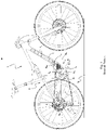
- the mountain bike has a frame 1 with a rear suspension 2.
- the drive train 3 of the mountain bike includes a bottom bracket assembly AB with a bottom bracket shaft S B , a chain wheel Rc, a rear derailleur 4, a multiple sprocket cassette 5 arranged on the rear wheel axle A R and a drive chain 6.
- the mountain bike is equipped with an electric drive unit Du that supports the rider and is designed as a so-called center motor, i.e. is arranged in the area of the bottom bracket assembly AB , and which includes an electric motor device M EA according to the prior art.
- An energy storage device S E is assigned to the drive unit Du.
- the energy storage device S E for driving the motor device M EA of the drive unit Du is arranged in the down tube T L of the bicycle frame 1 . Due to the positioning of the motor device M EA and the energy storage device S E in front of and above the bottom bracket shaft S B , which has an in 1 drawn, common center of gravity C G of drive unit Du and energy storage device S E entails, it becomes clear that the center of gravity of the bicycle is shifted relatively far upwards and forwards by these assemblies, which have a considerable mass, with the in the introduction to the description stated disadvantages in terms of handling and driving safety.
- FIG. 2 shows a schematic representation of the essential assemblies and components of an e-mountain bike, which is equipped with an embodiment of a drive unit Du according to the present disclosure.
- the motor housing H M and thus also the battery housing H B of the energy storage device SE attached to the motor housing H M , can be or is connected to the frame 1 at two frame interfaces or fastening axes F M1 and F M2 .
- the energy storage device S E or the battery housing H B is connected to the motor housing H M by means of two attachment points or attachment axes F B1 and F B2 .
- the energy storage device S E can also be arranged together with the other assemblies of the drive unit Du in a single common housing.
- a drive unit Du designed coaxially to the bottom bracket shaft SB, in which the longitudinal axis of the motor shaft S M coincides with the longitudinal axis of the bottom bracket shaft SB , also enables a particularly compact design of the drive unit Du, so that compared to a non-coaxial drive unit such as according to 1 Freed up space in the bottom bracket area Di for other components, present in particular for the energy storage device S E with the battery cells C contained therein, as well as for the pivot bearing Ps or connection of the rear swing arm As can be used.
- the length of the chainstay or the distance between the rear wheel axle A R and the bottom bracket shaft S B can also be kept as short as possible due to the coaxial drive unit Du, which is particularly compact in diameter, and there is sufficient radial clearance in the bottom bracket area D 1 for the rear tire.
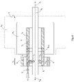
- FIGS. 3 shows in a highly schematized representation an example of a bottom bracket coaxial drive unit Du known from the prior art with a motor device M EB usually comprising a gearbox, in longitudinal section.
- M EB usually comprising a gearbox, in longitudinal section.
- T R the driver's torque
- Engine and transmission are in 3 not shown in more detail, but symbolized by the dotted surface area M EB , see however in this respect FIGS.
- this known drive unit Du for measuring the total driver torque T R which is composed of the torque T RL applied by the driver to the left-hand pedal crank and the torque T RR applied by the driver to the right-hand pedal crank, has its own torsion measurement hollow shaft SH needed.
- the total rider torque T R is passed through the hollow torsion measurement shaft S H which is firmly connected to the bottom bracket shaft S B on the right-hand side in the drawing, with the total rider torque T R being measured, for example without contact, by means of the torque sensor S T arranged radially outside of the hollow torsion measurement shaft S H becomes.
- the driver's total torque T R is then conducted to the output hollow shaft So of the drive unit Du via a driver torque coupling device designed as a freewheel D CR .
- the driver's total torque T R then combines with the engine torque coupling device, also designed as a freewheel D CM , to form a total drive torque T T .
- the total drive torque T T is passed through an output hollow shaft section Sos to the (not shown) sprocket Rc and thus into the drive train 3 of the bicycle - located in an axial region P A of the output hollow shaft So.
- this known drive unit Du in particular due to the hollow torsion measuring shaft S H required specifically for torque measurement, as well as due to the further assemblies to be arranged coaxially around the hollow torsion measuring shaft S H , sensor device S T , freewheels D CR and D CM and motor device M EB with electric motor and reduction gear, has a large radial diameter and overall takes up a comparatively large amount of space, as also stated in the introduction to the description of the present disclosure.
- the synopsis of 4 with the state of the art 3 shows further in particular that it allows the solution according to the present disclosure, completely on the torsion measurement hollow shaft S H according to 3 to renounce.
- the (usually relatively long) hollow torsion measuring shaft S H is required in the prior art because the torque is measured there by measuring the rotational torsional deformation of the hollow torsion measuring shaft S H by corresponding torsional stresses, i.e. those running in the circumferential direction of the hollow torsion measuring shaft S H Shear stresses are measured by means of the sensor device S T coaxially surrounding the torsion measuring hollow shaft S H , from which the total driver torque T S is then determined. Only then can driver torque T S and motor torque T M be combined on another shaft, here on the hollow output shaft So of the drive device Du.
- this method of measuring the driver's torque T R which is common in the prior art, means that in a central area of the bottom bracket shaft SB , three coaxially nested hollow shafts are required, not counting the bottom bracket shaft SB: First, the torsional Measuring hollow shaft S H , secondly a shaft arranged coaxially to the torsion measuring hollow shaft S H for receiving the sensor device S T , and finally the motor shaft S M arranged as a third shaft in the same axial area of the bottom bracket axis S B .
- reference number 140 designates the torsional hollow shaft S H (referred to there as the measuring shaft), reference number 184 the sensor device S T (referred to there as the coil body) and reference number 174 the motor shaft S M (referred to there as the support shaft or rotor shaft) .
- reference number 140 designates the torsional hollow shaft S H (referred to there as the measuring shaft), reference number 184 the sensor device S T (referred to there as the coil body) and reference number 174 the motor shaft S M (referred to there as the support shaft or rotor shaft) .
- some of these elements are not provided with reference numerals, but are also clearly recognizable.
- the drive unit according to you 4 can be dispensed with the nested two shafts of the torsion measurement hollow shaft S H and the sensor device S T , since the driver torque T s can be measured according to the present disclosure in the axial region P A of the same section Sos of the output hollow shaft So, through which also the engine torque is passed through.
- This radial widening of the output hollow shaft So in its section Sos generates material stresses running in the direction of rotation in the output hollow shaft So, which are preferably measured without contact using the sensor device S T enclosing the section Sos of the output hollow shaft So.
- This measurement of the driver's torque T R by detecting the circumferential stresses of the hollow output shaft So induced by a radial freewheel D CR is in fact not affected or significantly falsified by the engine torque T M , which also flows through the same section Sos of the hollow output shaft So, since the engine torque T M only shear stresses are generated in the circumferential direction in the section Sos of the hollow output shaft So.
- the shear stresses caused by the motor torque T M in the section Sos of the hollow output shaft So and the circumferential stresses also caused by the driver torque T R in the section Sos run in mutually perpendicular spatial directions and are therefore independent of one another at least in the first order or .approximation which for the usually required accuracy of the measurement of the driver's torque T R is completely sufficient. Greater accuracy is still possible by either measuring the motor torque T M in the motor or calculating it from the motor current and then applying an appropriate correction factor to the measured driver torque T R .
- the output hollow shaft So is used at the same time as a measuring hollow shaft, as a result of which the torsion measuring hollow shaft S H required in the prior art is completely eliminated.
- the measuring hollow shaft SH which is usually arranged in an axially central area of the drive unit Du
- the sensor device S T which is usually also in the form of a hollow shaft, in this axially central area of the drive unit Du.
- the sensor device S T can be arranged axially remote from the motor device M E in the section Sos of the output hollow shaft So, which is very clear 4 emerges.
- the engine device M E according to 4 can thus be made significantly more compact than that Motor device M EA in a drive unit Du known from the prior art (cf. the dashed line in 4 drawn outline of the engine device M EA according 3 ).
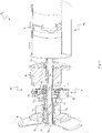
- FIG 5 shows a first embodiment of a drive unit Du according to the present disclosure in a sectional exploded perspective view. Only the drive housing H D is shown exploded or removed from the remaining components, so all other components are in their intended positions. All storage facilities or storage locations are marked with the reference symbol B.
- a motor device M E can be seen, which comprises an electric motor M, indicated only schematically, and a reduction gear designed here as a cycloidal gear G C .
- the cycloidal gear G C comprises two cycloidal gears Wc, which are mounted via bearing devices B, for example ball bearings, on two bearing seats F E arranged eccentrically and rotationally phase-shifted on the motor shaft S M .
- the cycloidal wheels W C have cycloidal teeth or cams along their outer circumference, which are formed in correspondingly shaped, in figure 5 wavy teeth, not shown, engage in an internal toothed area Si of the drive housing H D , the number of teeth of the internal toothed area Si being typically 1 greater than the number of teeth of the cycloidal gears Wc. This results in the very high transmission ratio that is typical for such a cycloidal gear Gc.
- the cycloidal wheels W C which rotate very slowly about their own axis relative to the engine speed due to the above-mentioned ratios of the number of teeth, share this rotational movement via the transmission pins P T Output flange Fo with.
- the rotation of the output flange Fo is then transmitted to the output hollow shaft So of the drive unit Du via the motor freewheel D CM .
- the driver's torque introduced via the bottom bracket shaft S B is also routed to the hollow output shaft So via the driver's freewheel D CR .
- the combined torques of the rider and motor are then transmitted as the total torque T T to the sprocket R C and from there to the drive train 3 of the bicycle.
- FIG. 6 shows the drive unit according to figure 5 in longitudinal section. Except the already in figure 5 The assemblies or components shown are in 6 also shows the curves of the left-hand driver torque T RL , the right-hand driver torque T RR and the motor torque T M . Also shown is the axial area P A through which both the total driver torque T R and the total motor torque T M flow during operation of the drive unit Du.
- the driver's total torque T R can be measured independently and at least in a first approximation unaffected by the engine torque T M due to the arrangement of the torque sensor device S T in the axial area P A , in which the driver's torque coupling device is also located in this embodiment in this case the freewheel D CR for the driver's torque T R is located.
- the radial deformation of the output hollow shaft So in the area of the output hollow shaft section Sos, or the resulting material stresses running in the circumferential direction of the output hollow shaft section Sos is measured by the sensor device S T , which occurs when the driver torques T RL or T RR is caused by the diameter expansion of the clamping roller freewheel D CR occurring, for example, as a clamping roller or general clamping body freewheel D CR embodied as a driver torque coupling device.
- the circumferential stress is measured on the outer diameter of the output hollow shaft section Sos in the area of the sprag freewheel D CR .
- These material stresses running in the circumferential direction are proportional to the driver's torque T R , so that the sensor device S T can be calibrated by the manufacturer according to the actual driver's torque T R .
- the elastic deformation due to the torsional or shearing stresses caused by the engine torque can be kept negligibly small by means of appropriate dimensioning of the output hollow shaft So, compared to the considerable radial expansion of the output hollow shaft section Sos by the sprag freewheel D CR .
- the measurement accuracy or the isolation of the driver torque T R from the engine torque T M can be further improved by specifically measuring only the hoop stress by the sensor device S T .
- these are arranged and aligned in the circumferential direction on the output hollow shaft section Sos, so that the shear stress due to torsion is hardly included in the measurement.
- a corresponding introduction of a magnetic field through the sensor device S T can optimize the measurement accuracy in the variant with magnetostrictive measurement.
- the material deformation direction of the output hollow shaft section Sos is used in the axial area P A and is distinguished from the sensor device in order to to isolate the driver torque T R from the motor torque T M in the measurement.
- the electrical power consumed by the motor M or the operating point of the motor M (motor torque as a function of e.g. current, voltage, speed, temperature) can be approximately determined
- Engine torque can be determined in order to correct any falsification of the measured value for the driver torque T R due to the shear stresses of the engine torque T M , which is only possible to a higher order.
- the free space that can be seen radially between the sensor device S T and the drive housing H D can be used for other assemblies, for example for parts of the reduction gear Gc, for electronic components such as motor and battery controllers or for energy stores.
- FIG. 7 shows a second embodiment of a drive unit Du in longitudinal section.
- the driver's torque T R is measured in the axial area P A of the output hollow shaft So, ie in the output hollow shaft section Sos.
- motor torque T M is physically separated from driver torque T R through axial region P A .
- the drive unit includes you according to 7 a hollow motor output shaft S OM arranged between the motor device M E and the motor torque input device D CM .
- the hollow motor output shaft S OM is arranged in the axial region P A coaxially to the output hollow shaft section Sos and radially outside of the output hollow shaft section Sos and is designed to be permeable to magnetic fields.
- the permeability of the hollow motor output shaft S OM for magnetic fields in the axial area P A can be achieved, for example, in that the hollow motor output shaft S OM at least in the axial area P A from a Paramagnetic material such as aluminum is formed, and also preferably receives a comparatively small wall thickness.
- This paramagnetic and preferably thin-walled section S OM of the hollow motor output shaft is dimensioned such that there is sufficient axial space for a magnetostrictive sensor S T in the axial area P A . In this way, the torque consisting only of the driver torque T R in the output hollow shaft section Sos can be measured without contact by means of the sensor device S T through the motor output hollow shaft S OM .
- the introduction of the motor torque T M to the output hollow shaft So via the motor freewheel D CM therefore only takes place downstream of the torque measurement (in the direction of the chain wheel Rc) with regard to the torque flow.
- the driver's torque T R can be measured completely isolated from the motor torque T M .
- the torque measurement at the hollow output shaft So can be measured in an axial region of the driver freewheel D CR , or also in an axial section Sos of the hollow output shaft So that is loaded entirely or predominantly only by torsion.
- driver torque T R and motor torque T M are in turn introduced into hollow output shaft So via freewheels D CR and D CM , respectively.
- the torque is measured by means of a sensor device S T in the area of an output hollow shaft section Sos, through which total torque T T , ie the sum of driver torque T R and engine torque T M , flows in this embodiment.
- the engine torque T M is preferably measured in real time or at very short time intervals determined and subtracted from the respectively measured total torque T T .
- the motor torque T M is preferably not measured directly, but calculated from the electrical power consumed by the motor.
- the accuracy of determining the driver torque T R is somewhat reduced by the calculation and subtraction of the motor torque T M , but can be at least partially compensated for by the easily accessible torque measurement in the area of the output hollow shaft section Sos.
- This arrangement also allows particularly cost-effective production, so that small compromises in the measurement accuracy of the driver's torque T R can be justified.
- Figures 9A to 9C show a fourth embodiment of a drive unit DU according to the present disclosure in a sectional view according to FIG Figure 9B and according to an enlarged section thereof Figure 9C , where the course of the cut and the direction of view on the cut are in Figure 9A are specified.
- the sprocket R C is in the representations of Figures 3 to 7 on the left side, accordingly the direction of view runs to the respective sectional plane Figures 3 to 7 , according to a bike 1 or 2 covered, front to back.
- the fourth embodiment according to Figures 9A to 9C is closely related to the first embodiment with regard to the principle of operation of the torque measurement and thus with regard to the power flows Figures 4 to 6 ajar.
- Figures 9B and 9C show the drive unit Du in longitudinal section.
- the curves of the left-hand driver torque T RL , the right-hand driver torque T RR and the engine torque T M are again represented by correspondingly different dashed lines.
- the axial area P A is again shown, through which both the total driver torque T R and the total motor torque T M flow during operation of the drive unit D U .
- FIG. 9B and 9C a motor device M E , here with a motor stator Ms, a motor rotor M R and a motor shaft S M .
- the motor shaft S M acts on a cycloidal gear Gc which, together with the motor shaft S M , comprises rotating eccentric bearing seats F E , externally toothed cycloidal wheels Wc meshing with an internal toothing area Si, further transmission pins P T , and an output flange Fo.
- the single-stage cycloidal gear G C is sufficient for the required reduction of the comparatively high speed of a motor rotor M R to the comparatively low speed of a chain wheel R C on a bicycle drive train 3.
- Figure 9C shows in an enlarged detail view Figure 9B in particular the axial area P A , through which both the total driver torque T R and the total engine torque T M flow in this embodiment during operation of the drive unit Du.
- the freewheel motor D CMA is preferably an axial freewheel, which contributes to being able to design the drive unit Du in a particularly space-saving manner, cf. the overview of the embodiment described above 4 , which also has an axial freewheel D CMA , according to the prior art 3 .
- the motor coasting D CM conducts, as in the embodiment according to FIG Figures 4 to 6 , the output torque of the cycloidal gear G C from the cycloidal gear output flange Fo to an output hollow shaft section Sos which defines the axial region P A in which the torque sensor device S T is located.
- the magnitude of the driver's total torque T R is different from the prior art 3 , measured directly in the axial area P A and in the output hollow shaft section Sos arranged there, through which both the driver's total torque T R and the motor torque T M flow.
- the driver's total torque T R is measured independently of the motor torque T M , which flows through the same material cross section of the output hollow shaft So in the output hollow shaft section Sos as the driver's total torque T R .
- driver torque coupling device D CR i.e. the driver torque freewheel, which allows motorized drive of the hollow output shaft and thus of the bicycle drive train 3 even when the driver is not pressing the pedals and the bottom bracket shaft S B is therefore stationary
- D CR the driver torque coupling device
- the driver torque freewheel which allows motorized drive of the hollow output shaft and thus of the bicycle drive train 3 even when the driver is not pressing the pedals and the bottom bracket shaft S B is therefore stationary
- This closing of the sprag freewheel D CR always occurs when the bottom bracket shaft S B rotates faster than the motor or transmission output flange Fo and thus faster than the output hollow shaft So.
- this difference in the rotational speed of the bottom bracket shaft S B and the output hollow shaft So is always a prerequisite for a driver's torque being able to be introduced into the drive train 3 at all, and is always present when the driver pedals actively or with a certain force.
- the sensor device S T comprises a coil body Bc, which carries three measuring coils C W1 , C W2 and Cw3 in the illustrated embodiment.
- the measuring coil Cwi on the left in relation to the drawing is used to detect the change in magnetic fields in the output hollow shaft section Sos in order to infer the material stresses in the output hollow shaft section Sos.
- the middle measurement coil C W2 in relation to the drawing is used to excite eddy currents and/or magnetic fields in the output hollow shaft section Sos.
- magnetoelasticity there are dependencies between mechanical and magnetic properties in the case of ferromagnetic materials, such as the present hollow output shaft So, which is preferably made of steel. Material loads and the associated geometric deformations (here the radial expansion of the output hollow shaft section Sos) change the magnetic properties of the output hollow shaft section Sos.
- the measuring coil Cwi on the left in relation to the drawing detects the changes caused by the stresses or deformations of the output hollow shaft section in the currents or magnetic fields induced by the drawing-related middle measuring coil C W2 in the output hollow shaft section Sos.
- the measurement coil C W3 on the right-hand side of the drawing is used for temperature compensation of the measurement. This is necessary because temperature fluctuations of the order of magnitude of 100 K can occur in the area of the sensor device S T , in particular due to the heat generated by the electric motor M, Ms, M R .
- the measuring coils C W1 , C W2 , C W3 are in the form of windings running in a circumferential direction.
- the coil body B C can be manufactured very simply and inexpensively, and the sensor device S T can also withstand demanding loads and the associated vibrations or temperature loads.
- the details on the manufacture and design of the measuring coils Cwi, C W2 , C W3 and their wiring and evaluation electronics are the subject of the aforementioned US application US'370, the disclosure of which is incorporated by reference into the disclosure of the present patent application.
- the output hollow shaft section Sos has two circumferential recessed grooves G R1 and G R2 .
- the presence and/or the selection of the size and the geometric shape of one or both recess grooves G R1 and G R2 influence the characteristic curve of the measurement by the sensor device S T .
- the sensitivity and accuracy of the measurement of the driver's torque T R by the sensor device S T can be optimized by a suitable choice and design of one or both recess grooves G R1 and G R2 .
- the coil body B C is arranged on a left-hand inside projection Bs of the right-hand housing cover C HR formed by the bearing seat of the bearing B R of the output hollow shaft So.
- This arrangement makes sense due to the double use of the bearing seat projection Bs, and has the further advantage that the deformations of the bottom bracket shaft and/or the housing cover C HR that occur during operation of the drive unit Du due to the high chain tensile forces or pedal forces also affect the coil body Tell B C. This ensures that the coil body B C remains largely coaxial with the measuring body, ie with the output hollow shaft section Sos, even when the drive unit Du is heavily loaded.
Landscapes
- Engineering & Computer Science (AREA)
- Mechanical Engineering (AREA)
- Chemical & Material Sciences (AREA)
- Combustion & Propulsion (AREA)
- Transportation (AREA)
- Force Measurement Appropriate To Specific Purposes (AREA)
- Connection Of Motors, Electrical Generators, Mechanical Devices, And The Like (AREA)
Applications Claiming Priority (2)
| Application Number | Priority Date | Filing Date | Title |
|---|---|---|---|
| DE102021002093 | 2021-04-21 | ||
| DE102022109482.0A DE102022109482A1 (de) | 2021-04-21 | 2022-04-19 | Elektrische Fahrrad-Antriebseinheit mit Drehmomentmesseinrichtung |
Publications (2)
| Publication Number | Publication Date |
|---|---|
| EP4082880A1 true EP4082880A1 (fr) | 2022-11-02 |
| EP4082880B1 EP4082880B1 (fr) | 2024-01-31 |
Family
ID=81346308
Family Applications (1)
| Application Number | Title | Priority Date | Filing Date |
|---|---|---|---|
| EP22020184.2A Active EP4082880B1 (fr) | 2021-04-21 | 2022-04-21 | Unité d'entraînement de bicyclette électrique pourvu de dispositif de détection de couple |
Country Status (4)
| Country | Link |
|---|---|
| US (1) | US12576946B2 (fr) |
| EP (1) | EP4082880B1 (fr) |
| CN (1) | CN115214836A (fr) |
| TW (1) | TW202246116A (fr) |
Cited By (2)
| Publication number | Priority date | Publication date | Assignee | Title |
|---|---|---|---|---|
| EP4481232A1 (fr) * | 2023-06-21 | 2024-12-25 | SRAM Deutschland GmbH | Transmission cycloidale et unite d'entrainement electrique pour bicyclette avec transmission cycloidale |
| WO2026068727A1 (fr) * | 2024-09-27 | 2026-04-02 | Brose Antriebstechnik GmbH & Co. Kommanditgesellschaft | Ensemble arbre pour une unité d'entraînement d'un vélo électrique et procédé pour déterminer une force transmise entre deux arbres |
Families Citing this family (5)
| Publication number | Priority date | Publication date | Assignee | Title |
|---|---|---|---|---|
| DE102023204103B3 (de) * | 2023-05-04 | 2024-05-16 | Zf Friedrichshafen Ag | Freilaufvorrichtung für einen Antriebsstrang eines Fahrrads und Fahrrad mit einer solchen Freilaufvorrichtung |
| US20250026440A1 (en) * | 2023-07-17 | 2025-01-23 | Delta Electronics, Inc. | Power module of electric assisted bicycle |
| TWI867985B (zh) | 2024-03-21 | 2024-12-21 | 達詳科技股份有限公司 | 自行車之中置馬達傳動裝置 |
| WO2026009163A1 (fr) * | 2024-07-01 | 2026-01-08 | Tq-Systems Gmbh | Unité de charge et d'entraînement électrique pour une machine de conditionnement physique |
| WO2026057683A1 (fr) * | 2024-09-11 | 2026-03-19 | Egym Se | Appareil, système et procédé d'entraînement de la force musculaire |
Citations (2)
| Publication number | Priority date | Publication date | Assignee | Title |
|---|---|---|---|---|
| DE202014010823U1 (de) | 2013-03-20 | 2016-10-13 | Tq-Systems Gmbh | Harmonisches-Pinring-Getriebe |
| DE102016120544A1 (de) * | 2016-10-27 | 2018-05-03 | Amprio Gmbh | Antriebseinrichtung für ein elektromotorisch und mit Muskelkraft hybrid betriebenes Elektrofahrrad |
Family Cites Families (16)
| Publication number | Priority date | Publication date | Assignee | Title |
|---|---|---|---|---|
| EP2216242B1 (fr) * | 2009-02-04 | 2012-04-04 | Electragil GmbH | Dispositif d'entraînement |
| DE102009029653B4 (de) | 2009-09-22 | 2021-04-22 | Robert Bosch Gmbh | Kurbeltrieb für ein Fahrrad |
| JP5442814B2 (ja) * | 2012-07-12 | 2014-03-12 | 株式会社シマノ | 自転車用駆動ユニット |
| WO2014103212A1 (fr) * | 2012-12-28 | 2014-07-03 | パナソニック株式会社 | Bicyclette électrique |
| DE102013211436B4 (de) * | 2013-06-18 | 2016-06-23 | Ovalo Gmbh | Tretlager für ein Fahrrad sowie ein Fahrrad |
| DE102014016719A1 (de) | 2014-11-13 | 2016-05-19 | Ali Dastrandj | Antriebseinheit und Fahrzeug |
| DE102015210503A1 (de) * | 2015-06-09 | 2016-12-15 | Sram Deutschland Gmbh | Hinterrad-Ritzelanordnung für ein Fahrrad, insbesondere ein Pedelec |
| DE102016122172B4 (de) * | 2016-07-25 | 2018-02-01 | Trafag Ag | Sensorkopf für einen Kraft- oder Drehmomentsensor |
| DE102016122845A1 (de) * | 2016-11-28 | 2018-05-30 | Tq-Systems Gmbh | Harmonisches Pinring-Getriebe, Drehmomentmessvorrichtung und Freilaufanordnung |
| DE102016123095A1 (de) | 2016-11-30 | 2018-05-30 | National Cheng Kung University | Vorrichtung zum erfassen des kurbel-tretdrehmoments für elektrofahrrad |
| CA2962515C (fr) * | 2017-02-21 | 2024-06-25 | Benoit Cloutier | Detecteur de couple destine a une bicyclette electrique |
| DE102017111770A1 (de) * | 2017-05-30 | 2018-12-06 | Disco Drives Kirschey Gmbh | Antriebseinheit für ein Fahrrad |
| WO2019003260A1 (fr) | 2017-06-26 | 2019-01-03 | ヤマハ発動機株式会社 | Fauteuil roulant à assistance motorisée, unité d'assistance motorisée pour fauteuil roulant, dispositif de commande pour fauteuil roulant à assistance motorisée, procédé de commande pour fauteuil roulant à assistance motorisée, et programme |
| DE102018200061A1 (de) | 2018-01-04 | 2019-07-04 | Robert Bosch Gmbh | Antriebsanordnung und mit Muskelkraft und zusätzlich mit Motorkraft antreibbares Fahrzeug |
| CN211599454U (zh) | 2020-01-03 | 2020-09-29 | 珠海市钧兴机电有限公司 | 电动助力车谐波传动系统 |
| DE102020203711B4 (de) | 2020-03-23 | 2021-10-07 | Zf Friedrichshafen Ag | Antriebseinheit |
-
2022
- 2022-04-20 TW TW111115073A patent/TW202246116A/zh unknown
- 2022-04-20 CN CN202210415630.XA patent/CN115214836A/zh active Pending
- 2022-04-21 EP EP22020184.2A patent/EP4082880B1/fr active Active
- 2022-04-21 US US17/725,724 patent/US12576946B2/en active Active
Patent Citations (2)
| Publication number | Priority date | Publication date | Assignee | Title |
|---|---|---|---|---|
| DE202014010823U1 (de) | 2013-03-20 | 2016-10-13 | Tq-Systems Gmbh | Harmonisches-Pinring-Getriebe |
| DE102016120544A1 (de) * | 2016-10-27 | 2018-05-03 | Amprio Gmbh | Antriebseinrichtung für ein elektromotorisch und mit Muskelkraft hybrid betriebenes Elektrofahrrad |
Cited By (2)
| Publication number | Priority date | Publication date | Assignee | Title |
|---|---|---|---|---|
| EP4481232A1 (fr) * | 2023-06-21 | 2024-12-25 | SRAM Deutschland GmbH | Transmission cycloidale et unite d'entrainement electrique pour bicyclette avec transmission cycloidale |
| WO2026068727A1 (fr) * | 2024-09-27 | 2026-04-02 | Brose Antriebstechnik GmbH & Co. Kommanditgesellschaft | Ensemble arbre pour une unité d'entraînement d'un vélo électrique et procédé pour déterminer une force transmise entre deux arbres |
Also Published As
| Publication number | Publication date |
|---|---|
| EP4082880B1 (fr) | 2024-01-31 |
| US12576946B2 (en) | 2026-03-17 |
| CN115214836A (zh) | 2022-10-21 |
| TW202246116A (zh) | 2022-12-01 |
| US20220340231A1 (en) | 2022-10-27 |
Similar Documents
| Publication | Publication Date | Title |
|---|---|---|
| EP4082880B1 (fr) | Unité d'entraînement de bicyclette électrique pourvu de dispositif de détection de couple | |
| EP3315395B1 (fr) | Dispositif d'entraînement pour un moteur électrique et bicyclette électrique pourvue d'entraînement hybride propulsé par force musculaire | |
| DE102012104065B4 (de) | Fahrrad-Kraftmessanordnung | |
| DE102013011504B4 (de) | Fahrradantriebseinheit | |
| DE102013004886A1 (de) | Steuerungseinrichtung für ein Fahrrad | |
| EP2156156A1 (fr) | Dispositif d'entraînement comprenant un arbre d'entraînement et un dispositif pour déterminer un couple | |
| EP2152566A1 (fr) | Dispositif d'entraînement comprenant un arbre d'entraînement et des manivelles d'entraînement | |
| DE102009029653B4 (de) | Kurbeltrieb für ein Fahrrad | |
| WO2012010344A1 (fr) | Palier de pédalier pour bicyclette | |
| EP2470417B1 (fr) | Unité d'entraînement | |
| WO2017012753A1 (fr) | Dispositif de mesure pour mesurer le couple de rotation sur un arbre, mécanisme bielle-manivelle et véhicule | |
| DE102017202507A1 (de) | Drehmomenterfassungseinrichtung, Antrieb und Arbeitsvorrichtung | |
| DE102012214332A1 (de) | Leistungssensorik für Fahrräder | |
| DE102022109482A1 (de) | Elektrische Fahrrad-Antriebseinheit mit Drehmomentmesseinrichtung | |
| EP3626593B1 (fr) | Palier de pédalier compact à manche de mesure de couple | |
| EP4330121B1 (fr) | Dispositif d'entraînement pour une bicyclette électrique et bicyclette électrique | |
| DE102010026810A1 (de) | Elektrofahrrad mit Elektromotor | |
| DE102021110719B3 (de) | Antriebsvorrichtung für ein Elektrofahrrad und Elektrofahrrad | |
| DE102015201815B3 (de) | Zahnkranzpaket und zugehöriger Antriebsstrang | |
| DE102021122525A1 (de) | Tretlager und Fahrzeug | |
| DE102024119315B4 (de) | Messvorrichtung für ein Fahrrad, Antriebsvorrichtung für ein Fahrrad, Fahrrad und Verfahren zum Betreiben einer Antriebsvorrichtung | |
| DE102024101033B3 (de) | Tretantrieb mit mindestens einem Kraftsensor zur Messung der Trittkraft an dem Tretantrieb | |
| DE102025114213B3 (de) | Verfahren und Steuereinrichtung zur Ermittlung einer mechanischen Belastung an einer Tretkurbeleinheit eines Fahrrades | |
| DE102016205541A1 (de) | Antriebsvorrichtung mit einem sensor | |
| DE102024112259B4 (de) | Antriebsvorrichtung für ein Fahrrad |
Legal Events
| Date | Code | Title | Description |
|---|---|---|---|
| PUAI | Public reference made under article 153(3) epc to a published international application that has entered the european phase |
Free format text: ORIGINAL CODE: 0009012 |
|
| STAA | Information on the status of an ep patent application or granted ep patent |
Free format text: STATUS: THE APPLICATION HAS BEEN PUBLISHED |
|
| AK | Designated contracting states |
Kind code of ref document: A1 Designated state(s): AL AT BE BG CH CY CZ DE DK EE ES FI FR GB GR HR HU IE IS IT LI LT LU LV MC MK MT NL NO PL PT RO RS SE SI SK SM TR |
|
| STAA | Information on the status of an ep patent application or granted ep patent |
Free format text: STATUS: REQUEST FOR EXAMINATION WAS MADE |
|
| 17P | Request for examination filed |
Effective date: 20230315 |
|
| GRAP | Despatch of communication of intention to grant a patent |
Free format text: ORIGINAL CODE: EPIDOSNIGR1 |
|
| STAA | Information on the status of an ep patent application or granted ep patent |
Free format text: STATUS: GRANT OF PATENT IS INTENDED |
|
| INTG | Intention to grant announced |
Effective date: 20230904 |
|
| GRAS | Grant fee paid |
Free format text: ORIGINAL CODE: EPIDOSNIGR3 |
|
| GRAA | (expected) grant |
Free format text: ORIGINAL CODE: 0009210 |
|
| STAA | Information on the status of an ep patent application or granted ep patent |
Free format text: STATUS: THE PATENT HAS BEEN GRANTED |
|
| AK | Designated contracting states |
Kind code of ref document: B1 Designated state(s): AL AT BE BG CH CY CZ DE DK EE ES FI FR GB GR HR HU IE IS IT LI LT LU LV MC MK MT NL NO PL PT RO RS SE SI SK SM TR |
|
| REG | Reference to a national code |
Ref country code: GB Ref legal event code: FG4D Free format text: NOT ENGLISH Ref country code: CH Ref legal event code: EP |
|
| REG | Reference to a national code |
Ref country code: DE Ref legal event code: R096 Ref document number: 502022000440 Country of ref document: DE |
|
| P01 | Opt-out of the competence of the unified patent court (upc) registered |
Effective date: 20240118 |
|
| REG | Reference to a national code |
Ref country code: IE Ref legal event code: FG4D Free format text: LANGUAGE OF EP DOCUMENT: GERMAN |
|
| REG | Reference to a national code |
Ref country code: LT Ref legal event code: MG9D |
|
| REG | Reference to a national code |
Ref country code: NL Ref legal event code: MP Effective date: 20240131 |
|
| PG25 | Lapsed in a contracting state [announced via postgrant information from national office to epo] |
Ref country code: IS Free format text: LAPSE BECAUSE OF FAILURE TO SUBMIT A TRANSLATION OF THE DESCRIPTION OR TO PAY THE FEE WITHIN THE PRESCRIBED TIME-LIMIT Effective date: 20240531 |
|
| PG25 | Lapsed in a contracting state [announced via postgrant information from national office to epo] |
Ref country code: LT Free format text: LAPSE BECAUSE OF FAILURE TO SUBMIT A TRANSLATION OF THE DESCRIPTION OR TO PAY THE FEE WITHIN THE PRESCRIBED TIME-LIMIT Effective date: 20240131 |
|
| PG25 | Lapsed in a contracting state [announced via postgrant information from national office to epo] |
Ref country code: GR Free format text: LAPSE BECAUSE OF FAILURE TO SUBMIT A TRANSLATION OF THE DESCRIPTION OR TO PAY THE FEE WITHIN THE PRESCRIBED TIME-LIMIT Effective date: 20240501 |
|
| PG25 | Lapsed in a contracting state [announced via postgrant information from national office to epo] |
Ref country code: RS Free format text: LAPSE BECAUSE OF FAILURE TO SUBMIT A TRANSLATION OF THE DESCRIPTION OR TO PAY THE FEE WITHIN THE PRESCRIBED TIME-LIMIT Effective date: 20240430 Ref country code: HR Free format text: LAPSE BECAUSE OF FAILURE TO SUBMIT A TRANSLATION OF THE DESCRIPTION OR TO PAY THE FEE WITHIN THE PRESCRIBED TIME-LIMIT Effective date: 20240131 Ref country code: NL Free format text: LAPSE BECAUSE OF FAILURE TO SUBMIT A TRANSLATION OF THE DESCRIPTION OR TO PAY THE FEE WITHIN THE PRESCRIBED TIME-LIMIT Effective date: 20240131 |
|
| PG25 | Lapsed in a contracting state [announced via postgrant information from national office to epo] |
Ref country code: ES Free format text: LAPSE BECAUSE OF FAILURE TO SUBMIT A TRANSLATION OF THE DESCRIPTION OR TO PAY THE FEE WITHIN THE PRESCRIBED TIME-LIMIT Effective date: 20240131 |
|
| PG25 | Lapsed in a contracting state [announced via postgrant information from national office to epo] |
Ref country code: RS Free format text: LAPSE BECAUSE OF FAILURE TO SUBMIT A TRANSLATION OF THE DESCRIPTION OR TO PAY THE FEE WITHIN THE PRESCRIBED TIME-LIMIT Effective date: 20240430 Ref country code: NO Free format text: LAPSE BECAUSE OF FAILURE TO SUBMIT A TRANSLATION OF THE DESCRIPTION OR TO PAY THE FEE WITHIN THE PRESCRIBED TIME-LIMIT Effective date: 20240430 Ref country code: NL Free format text: LAPSE BECAUSE OF FAILURE TO SUBMIT A TRANSLATION OF THE DESCRIPTION OR TO PAY THE FEE WITHIN THE PRESCRIBED TIME-LIMIT Effective date: 20240131 Ref country code: LT Free format text: LAPSE BECAUSE OF FAILURE TO SUBMIT A TRANSLATION OF THE DESCRIPTION OR TO PAY THE FEE WITHIN THE PRESCRIBED TIME-LIMIT Effective date: 20240131 Ref country code: IS Free format text: LAPSE BECAUSE OF FAILURE TO SUBMIT A TRANSLATION OF THE DESCRIPTION OR TO PAY THE FEE WITHIN THE PRESCRIBED TIME-LIMIT Effective date: 20240531 Ref country code: HR Free format text: LAPSE BECAUSE OF FAILURE TO SUBMIT A TRANSLATION OF THE DESCRIPTION OR TO PAY THE FEE WITHIN THE PRESCRIBED TIME-LIMIT Effective date: 20240131 Ref country code: GR Free format text: LAPSE BECAUSE OF FAILURE TO SUBMIT A TRANSLATION OF THE DESCRIPTION OR TO PAY THE FEE WITHIN THE PRESCRIBED TIME-LIMIT Effective date: 20240501 Ref country code: FI Free format text: LAPSE BECAUSE OF FAILURE TO SUBMIT A TRANSLATION OF THE DESCRIPTION OR TO PAY THE FEE WITHIN THE PRESCRIBED TIME-LIMIT Effective date: 20240131 Ref country code: ES Free format text: LAPSE BECAUSE OF FAILURE TO SUBMIT A TRANSLATION OF THE DESCRIPTION OR TO PAY THE FEE WITHIN THE PRESCRIBED TIME-LIMIT Effective date: 20240131 Ref country code: BG Free format text: LAPSE BECAUSE OF FAILURE TO SUBMIT A TRANSLATION OF THE DESCRIPTION OR TO PAY THE FEE WITHIN THE PRESCRIBED TIME-LIMIT Effective date: 20240131 |
|
| PG25 | Lapsed in a contracting state [announced via postgrant information from national office to epo] |
Ref country code: PL Free format text: LAPSE BECAUSE OF FAILURE TO SUBMIT A TRANSLATION OF THE DESCRIPTION OR TO PAY THE FEE WITHIN THE PRESCRIBED TIME-LIMIT Effective date: 20240131 Ref country code: PT Free format text: LAPSE BECAUSE OF FAILURE TO SUBMIT A TRANSLATION OF THE DESCRIPTION OR TO PAY THE FEE WITHIN THE PRESCRIBED TIME-LIMIT Effective date: 20240531 |
|
| PG25 | Lapsed in a contracting state [announced via postgrant information from national office to epo] |
Ref country code: SE Free format text: LAPSE BECAUSE OF FAILURE TO SUBMIT A TRANSLATION OF THE DESCRIPTION OR TO PAY THE FEE WITHIN THE PRESCRIBED TIME-LIMIT Effective date: 20240131 Ref country code: PT Free format text: LAPSE BECAUSE OF FAILURE TO SUBMIT A TRANSLATION OF THE DESCRIPTION OR TO PAY THE FEE WITHIN THE PRESCRIBED TIME-LIMIT Effective date: 20240531 Ref country code: PL Free format text: LAPSE BECAUSE OF FAILURE TO SUBMIT A TRANSLATION OF THE DESCRIPTION OR TO PAY THE FEE WITHIN THE PRESCRIBED TIME-LIMIT Effective date: 20240131 Ref country code: LV Free format text: LAPSE BECAUSE OF FAILURE TO SUBMIT A TRANSLATION OF THE DESCRIPTION OR TO PAY THE FEE WITHIN THE PRESCRIBED TIME-LIMIT Effective date: 20240131 |
|
| PG25 | Lapsed in a contracting state [announced via postgrant information from national office to epo] |
Ref country code: DK Free format text: LAPSE BECAUSE OF FAILURE TO SUBMIT A TRANSLATION OF THE DESCRIPTION OR TO PAY THE FEE WITHIN THE PRESCRIBED TIME-LIMIT Effective date: 20240131 |
|
| PG25 | Lapsed in a contracting state [announced via postgrant information from national office to epo] |
Ref country code: SM Free format text: LAPSE BECAUSE OF FAILURE TO SUBMIT A TRANSLATION OF THE DESCRIPTION OR TO PAY THE FEE WITHIN THE PRESCRIBED TIME-LIMIT Effective date: 20240131 |
|
| PG25 | Lapsed in a contracting state [announced via postgrant information from national office to epo] |
Ref country code: EE Free format text: LAPSE BECAUSE OF FAILURE TO SUBMIT A TRANSLATION OF THE DESCRIPTION OR TO PAY THE FEE WITHIN THE PRESCRIBED TIME-LIMIT Effective date: 20240131 Ref country code: CZ Free format text: LAPSE BECAUSE OF FAILURE TO SUBMIT A TRANSLATION OF THE DESCRIPTION OR TO PAY THE FEE WITHIN THE PRESCRIBED TIME-LIMIT Effective date: 20240131 |
|
| PG25 | Lapsed in a contracting state [announced via postgrant information from national office to epo] |
Ref country code: SK Free format text: LAPSE BECAUSE OF FAILURE TO SUBMIT A TRANSLATION OF THE DESCRIPTION OR TO PAY THE FEE WITHIN THE PRESCRIBED TIME-LIMIT Effective date: 20240131 |
|
| REG | Reference to a national code |
Ref country code: DE Ref legal event code: R026 Ref document number: 502022000440 Country of ref document: DE |
|
| PG25 | Lapsed in a contracting state [announced via postgrant information from national office to epo] |
Ref country code: SM Free format text: LAPSE BECAUSE OF FAILURE TO SUBMIT A TRANSLATION OF THE DESCRIPTION OR TO PAY THE FEE WITHIN THE PRESCRIBED TIME-LIMIT Effective date: 20240131 Ref country code: SK Free format text: LAPSE BECAUSE OF FAILURE TO SUBMIT A TRANSLATION OF THE DESCRIPTION OR TO PAY THE FEE WITHIN THE PRESCRIBED TIME-LIMIT Effective date: 20240131 Ref country code: RO Free format text: LAPSE BECAUSE OF FAILURE TO SUBMIT A TRANSLATION OF THE DESCRIPTION OR TO PAY THE FEE WITHIN THE PRESCRIBED TIME-LIMIT Effective date: 20240131 Ref country code: EE Free format text: LAPSE BECAUSE OF FAILURE TO SUBMIT A TRANSLATION OF THE DESCRIPTION OR TO PAY THE FEE WITHIN THE PRESCRIBED TIME-LIMIT Effective date: 20240131 Ref country code: DK Free format text: LAPSE BECAUSE OF FAILURE TO SUBMIT A TRANSLATION OF THE DESCRIPTION OR TO PAY THE FEE WITHIN THE PRESCRIBED TIME-LIMIT Effective date: 20240131 Ref country code: CZ Free format text: LAPSE BECAUSE OF FAILURE TO SUBMIT A TRANSLATION OF THE DESCRIPTION OR TO PAY THE FEE WITHIN THE PRESCRIBED TIME-LIMIT Effective date: 20240131 |
|
| PLBI | Opposition filed |
Free format text: ORIGINAL CODE: 0009260 |
|
| PLAB | Opposition data, opponent's data or that of the opponent's representative modified |
Free format text: ORIGINAL CODE: 0009299OPPO |
|
| PLAX | Notice of opposition and request to file observation + time limit sent |
Free format text: ORIGINAL CODE: EPIDOSNOBS2 |
|
| PG25 | Lapsed in a contracting state [announced via postgrant information from national office to epo] |
Ref country code: MC Free format text: LAPSE BECAUSE OF FAILURE TO SUBMIT A TRANSLATION OF THE DESCRIPTION OR TO PAY THE FEE WITHIN THE PRESCRIBED TIME-LIMIT Effective date: 20240131 |
|
| PG25 | Lapsed in a contracting state [announced via postgrant information from national office to epo] |
Ref country code: MC Free format text: LAPSE BECAUSE OF FAILURE TO SUBMIT A TRANSLATION OF THE DESCRIPTION OR TO PAY THE FEE WITHIN THE PRESCRIBED TIME-LIMIT Effective date: 20240131 |
|
| 26 | Opposition filed |
Opponent name: ZF FRIEDRICHSHAFEN AG Effective date: 20241030 |
|
| PG25 | Lapsed in a contracting state [announced via postgrant information from national office to epo] |
Ref country code: IT Free format text: LAPSE BECAUSE OF FAILURE TO SUBMIT A TRANSLATION OF THE DESCRIPTION OR TO PAY THE FEE WITHIN THE PRESCRIBED TIME-LIMIT Effective date: 20240131 |
|
| R26 | Opposition filed (corrected) |
Opponent name: ZF FRIEDRICHSHAFEN AG Effective date: 20241030 |
|
| PG25 | Lapsed in a contracting state [announced via postgrant information from national office to epo] |
Ref country code: LU Free format text: LAPSE BECAUSE OF NON-PAYMENT OF DUE FEES Effective date: 20240421 |
|
| REG | Reference to a national code |
Ref country code: BE Ref legal event code: MM Effective date: 20240430 |
|
| PG25 | Lapsed in a contracting state [announced via postgrant information from national office to epo] |
Ref country code: LU Free format text: LAPSE BECAUSE OF NON-PAYMENT OF DUE FEES Effective date: 20240421 Ref country code: IT Free format text: LAPSE BECAUSE OF FAILURE TO SUBMIT A TRANSLATION OF THE DESCRIPTION OR TO PAY THE FEE WITHIN THE PRESCRIBED TIME-LIMIT Effective date: 20240131 |
|
| PG25 | Lapsed in a contracting state [announced via postgrant information from national office to epo] |
Ref country code: BE Free format text: LAPSE BECAUSE OF NON-PAYMENT OF DUE FEES Effective date: 20240430 |
|
| PG25 | Lapsed in a contracting state [announced via postgrant information from national office to epo] |
Ref country code: BE Free format text: LAPSE BECAUSE OF NON-PAYMENT OF DUE FEES Effective date: 20240430 |
|
| PLBB | Reply of patent proprietor to notice(s) of opposition received |
Free format text: ORIGINAL CODE: EPIDOSNOBS3 |
|
| PG25 | Lapsed in a contracting state [announced via postgrant information from national office to epo] |
Ref country code: IE Free format text: LAPSE BECAUSE OF NON-PAYMENT OF DUE FEES Effective date: 20240421 |
|
| PG25 | Lapsed in a contracting state [announced via postgrant information from national office to epo] |
Ref country code: SI Free format text: LAPSE BECAUSE OF FAILURE TO SUBMIT A TRANSLATION OF THE DESCRIPTION OR TO PAY THE FEE WITHIN THE PRESCRIBED TIME-LIMIT Effective date: 20240131 |
|
| PGFP | Annual fee paid to national office [announced via postgrant information from national office to epo] |
Ref country code: DE Payment date: 20250404 Year of fee payment: 4 |
|
| PGFP | Annual fee paid to national office [announced via postgrant information from national office to epo] |
Ref country code: FR Payment date: 20250425 Year of fee payment: 4 |
|
| PGFP | Annual fee paid to national office [announced via postgrant information from national office to epo] |
Ref country code: AT Payment date: 20250721 Year of fee payment: 4 |
|
| PG25 | Lapsed in a contracting state [announced via postgrant information from national office to epo] |
Ref country code: CY Free format text: LAPSE BECAUSE OF FAILURE TO SUBMIT A TRANSLATION OF THE DESCRIPTION OR TO PAY THE FEE WITHIN THE PRESCRIBED TIME-LIMIT; INVALID AB INITIO Effective date: 20220421 |
|
| PLAB | Opposition data, opponent's data or that of the opponent's representative modified |
Free format text: ORIGINAL CODE: 0009299OPPO |
|
| PG25 | Lapsed in a contracting state [announced via postgrant information from national office to epo] |
Ref country code: HU Free format text: LAPSE BECAUSE OF FAILURE TO SUBMIT A TRANSLATION OF THE DESCRIPTION OR TO PAY THE FEE WITHIN THE PRESCRIBED TIME-LIMIT; INVALID AB INITIO Effective date: 20220421 |
|
| R26 | Opposition filed (corrected) |
Opponent name: ZF FRIEDRICHSHAFEN AG Effective date: 20241030 |
|
| REG | Reference to a national code |
Ref country code: CH Ref legal event code: H13 Free format text: ST27 STATUS EVENT CODE: U-0-0-H10-H13 (AS PROVIDED BY THE NATIONAL OFFICE) Effective date: 20251125 |
|
| PG25 | Lapsed in a contracting state [announced via postgrant information from national office to epo] |
Ref country code: CH Free format text: LAPSE BECAUSE OF NON-PAYMENT OF DUE FEES Effective date: 20250430 |