EP4481232A1 - Transmission cycloidale et unite d'entrainement electrique pour bicyclette avec transmission cycloidale - Google Patents
Transmission cycloidale et unite d'entrainement electrique pour bicyclette avec transmission cycloidale Download PDFInfo
- Publication number
- EP4481232A1 EP4481232A1 EP24020183.0A EP24020183A EP4481232A1 EP 4481232 A1 EP4481232 A1 EP 4481232A1 EP 24020183 A EP24020183 A EP 24020183A EP 4481232 A1 EP4481232 A1 EP 4481232A1
- Authority
- EP
- European Patent Office
- Prior art keywords
- cycloid
- cycloidal
- drive unit
- gear
- counter
- Prior art date
- Legal status (The legal status is an assumption and is not a legal conclusion. Google has not performed a legal analysis and makes no representation as to the accuracy of the status listed.)
- Pending
Links
Images


Classifications
-
- F—MECHANICAL ENGINEERING; LIGHTING; HEATING; WEAPONS; BLASTING
- F16—ENGINEERING ELEMENTS AND UNITS; GENERAL MEASURES FOR PRODUCING AND MAINTAINING EFFECTIVE FUNCTIONING OF MACHINES OR INSTALLATIONS; THERMAL INSULATION IN GENERAL
- F16H—GEARING
- F16H55/00—Elements with teeth or friction surfaces for conveying motion; Worms, pulleys or sheaves for gearing mechanisms
- F16H55/02—Toothed members; Worms
- F16H55/08—Profiling
-
- B—PERFORMING OPERATIONS; TRANSPORTING
- B62—LAND VEHICLES FOR TRAVELLING OTHERWISE THAN ON RAILS
- B62M—RIDER PROPULSION OF WHEELED VEHICLES OR SLEDGES; POWERED PROPULSION OF SLEDGES OR SINGLE-TRACK CYCLES; TRANSMISSIONS SPECIALLY ADAPTED FOR SUCH VEHICLES
- B62M11/00—Transmissions characterised by the use of interengaging toothed wheels or frictionally-engaging wheels
- B62M11/04—Transmissions characterised by the use of interengaging toothed wheels or frictionally-engaging wheels of changeable ratio
- B62M11/14—Transmissions characterised by the use of interengaging toothed wheels or frictionally-engaging wheels of changeable ratio with planetary gears
- B62M11/145—Transmissions characterised by the use of interengaging toothed wheels or frictionally-engaging wheels of changeable ratio with planetary gears built in, or adjacent to, the bottom bracket
-
- B—PERFORMING OPERATIONS; TRANSPORTING
- B62—LAND VEHICLES FOR TRAVELLING OTHERWISE THAN ON RAILS
- B62M—RIDER PROPULSION OF WHEELED VEHICLES OR SLEDGES; POWERED PROPULSION OF SLEDGES OR SINGLE-TRACK CYCLES; TRANSMISSIONS SPECIALLY ADAPTED FOR SUCH VEHICLES
- B62M11/00—Transmissions characterised by the use of interengaging toothed wheels or frictionally-engaging wheels
- B62M11/04—Transmissions characterised by the use of interengaging toothed wheels or frictionally-engaging wheels of changeable ratio
-
- B—PERFORMING OPERATIONS; TRANSPORTING
- B62—LAND VEHICLES FOR TRAVELLING OTHERWISE THAN ON RAILS
- B62J—CYCLE SADDLES OR SEATS; AUXILIARY DEVICES OR ACCESSORIES SPECIALLY ADAPTED TO CYCLES AND NOT OTHERWISE PROVIDED FOR, e.g. ARTICLE CARRIERS OR CYCLE PROTECTORS
- B62J45/00—Electrical equipment arrangements specially adapted for use as accessories on cycles, not otherwise provided for
- B62J45/40—Sensor arrangements; Mounting thereof
- B62J45/41—Sensor arrangements; Mounting thereof characterised by the type of sensor
- B62J45/411—Torque sensors
-
- B—PERFORMING OPERATIONS; TRANSPORTING
- B62—LAND VEHICLES FOR TRAVELLING OTHERWISE THAN ON RAILS
- B62J—CYCLE SADDLES OR SEATS; AUXILIARY DEVICES OR ACCESSORIES SPECIALLY ADAPTED TO CYCLES AND NOT OTHERWISE PROVIDED FOR, e.g. ARTICLE CARRIERS OR CYCLE PROTECTORS
- B62J45/00—Electrical equipment arrangements specially adapted for use as accessories on cycles, not otherwise provided for
- B62J45/40—Sensor arrangements; Mounting thereof
- B62J45/41—Sensor arrangements; Mounting thereof characterised by the type of sensor
- B62J45/412—Speed sensors
-
- B—PERFORMING OPERATIONS; TRANSPORTING
- B62—LAND VEHICLES FOR TRAVELLING OTHERWISE THAN ON RAILS
- B62J—CYCLE SADDLES OR SEATS; AUXILIARY DEVICES OR ACCESSORIES SPECIALLY ADAPTED TO CYCLES AND NOT OTHERWISE PROVIDED FOR, e.g. ARTICLE CARRIERS OR CYCLE PROTECTORS
- B62J45/00—Electrical equipment arrangements specially adapted for use as accessories on cycles, not otherwise provided for
- B62J45/40—Sensor arrangements; Mounting thereof
- B62J45/41—Sensor arrangements; Mounting thereof characterised by the type of sensor
- B62J45/413—Rotation sensors
-
- B—PERFORMING OPERATIONS; TRANSPORTING
- B62—LAND VEHICLES FOR TRAVELLING OTHERWISE THAN ON RAILS
- B62J—CYCLE SADDLES OR SEATS; AUXILIARY DEVICES OR ACCESSORIES SPECIALLY ADAPTED TO CYCLES AND NOT OTHERWISE PROVIDED FOR, e.g. ARTICLE CARRIERS OR CYCLE PROTECTORS
- B62J45/00—Electrical equipment arrangements specially adapted for use as accessories on cycles, not otherwise provided for
- B62J45/40—Sensor arrangements; Mounting thereof
- B62J45/42—Sensor arrangements; Mounting thereof characterised by mounting
- B62J45/421—Sensor arrangements; Mounting thereof characterised by mounting at the pedal crank
-
- B—PERFORMING OPERATIONS; TRANSPORTING
- B62—LAND VEHICLES FOR TRAVELLING OTHERWISE THAN ON RAILS
- B62M—RIDER PROPULSION OF WHEELED VEHICLES OR SLEDGES; POWERED PROPULSION OF SLEDGES OR SINGLE-TRACK CYCLES; TRANSMISSIONS SPECIALLY ADAPTED FOR SUCH VEHICLES
- B62M11/00—Transmissions characterised by the use of interengaging toothed wheels or frictionally-engaging wheels
- B62M11/02—Transmissions characterised by the use of interengaging toothed wheels or frictionally-engaging wheels of unchangeable ratio
-
- B—PERFORMING OPERATIONS; TRANSPORTING
- B62—LAND VEHICLES FOR TRAVELLING OTHERWISE THAN ON RAILS
- B62M—RIDER PROPULSION OF WHEELED VEHICLES OR SLEDGES; POWERED PROPULSION OF SLEDGES OR SINGLE-TRACK CYCLES; TRANSMISSIONS SPECIALLY ADAPTED FOR SUCH VEHICLES
- B62M6/00—Rider propulsion of wheeled vehicles with additional source of power, e.g. combustion engine or electric motor
- B62M6/40—Rider propelled cycles with auxiliary electric motor
- B62M6/45—Control or actuating devices therefor
- B62M6/50—Control or actuating devices therefor characterised by detectors or sensors, or arrangement thereof
-
- B—PERFORMING OPERATIONS; TRANSPORTING
- B62—LAND VEHICLES FOR TRAVELLING OTHERWISE THAN ON RAILS
- B62M—RIDER PROPULSION OF WHEELED VEHICLES OR SLEDGES; POWERED PROPULSION OF SLEDGES OR SINGLE-TRACK CYCLES; TRANSMISSIONS SPECIALLY ADAPTED FOR SUCH VEHICLES
- B62M6/00—Rider propulsion of wheeled vehicles with additional source of power, e.g. combustion engine or electric motor
- B62M6/40—Rider propelled cycles with auxiliary electric motor
- B62M6/55—Rider propelled cycles with auxiliary electric motor power-driven at crank shafts parts
-
- F—MECHANICAL ENGINEERING; LIGHTING; HEATING; WEAPONS; BLASTING
- F16—ENGINEERING ELEMENTS AND UNITS; GENERAL MEASURES FOR PRODUCING AND MAINTAINING EFFECTIVE FUNCTIONING OF MACHINES OR INSTALLATIONS; THERMAL INSULATION IN GENERAL
- F16H—GEARING
- F16H1/00—Toothed gearings for conveying rotary motion
- F16H1/28—Toothed gearings for conveying rotary motion with gears having orbital motion
- F16H1/32—Toothed gearings for conveying rotary motion with gears having orbital motion in which the central axis of the gearing lies inside the periphery of an orbital gear
-
- F—MECHANICAL ENGINEERING; LIGHTING; HEATING; WEAPONS; BLASTING
- F16—ENGINEERING ELEMENTS AND UNITS; GENERAL MEASURES FOR PRODUCING AND MAINTAINING EFFECTIVE FUNCTIONING OF MACHINES OR INSTALLATIONS; THERMAL INSULATION IN GENERAL
- F16H—GEARING
- F16H55/00—Elements with teeth or friction surfaces for conveying motion; Worms, pulleys or sheaves for gearing mechanisms
- F16H55/02—Toothed members; Worms
- F16H55/06—Use of materials; Use of treatments of toothed members or worms to affect their intrinsic material properties
-
- F—MECHANICAL ENGINEERING; LIGHTING; HEATING; WEAPONS; BLASTING
- F16—ENGINEERING ELEMENTS AND UNITS; GENERAL MEASURES FOR PRODUCING AND MAINTAINING EFFECTIVE FUNCTIONING OF MACHINES OR INSTALLATIONS; THERMAL INSULATION IN GENERAL
- F16H—GEARING
- F16H55/00—Elements with teeth or friction surfaces for conveying motion; Worms, pulleys or sheaves for gearing mechanisms
- F16H55/02—Toothed members; Worms
- F16H55/08—Profiling
- F16H55/0826—Novikov-Wildhaber profile
-
- F—MECHANICAL ENGINEERING; LIGHTING; HEATING; WEAPONS; BLASTING
- F16—ENGINEERING ELEMENTS AND UNITS; GENERAL MEASURES FOR PRODUCING AND MAINTAINING EFFECTIVE FUNCTIONING OF MACHINES OR INSTALLATIONS; THERMAL INSULATION IN GENERAL
- F16H—GEARING
- F16H55/00—Elements with teeth or friction surfaces for conveying motion; Worms, pulleys or sheaves for gearing mechanisms
- F16H55/02—Toothed members; Worms
- F16H55/14—Construction providing resilience or vibration-damping
- F16H55/16—Construction providing resilience or vibration-damping relating to teeth only
-
- F—MECHANICAL ENGINEERING; LIGHTING; HEATING; WEAPONS; BLASTING
- F16—ENGINEERING ELEMENTS AND UNITS; GENERAL MEASURES FOR PRODUCING AND MAINTAINING EFFECTIVE FUNCTIONING OF MACHINES OR INSTALLATIONS; THERMAL INSULATION IN GENERAL
- F16H—GEARING
- F16H55/00—Elements with teeth or friction surfaces for conveying motion; Worms, pulleys or sheaves for gearing mechanisms
- F16H55/02—Toothed members; Worms
- F16H55/17—Toothed wheels
-
- F—MECHANICAL ENGINEERING; LIGHTING; HEATING; WEAPONS; BLASTING
- F16—ENGINEERING ELEMENTS AND UNITS; GENERAL MEASURES FOR PRODUCING AND MAINTAINING EFFECTIVE FUNCTIONING OF MACHINES OR INSTALLATIONS; THERMAL INSULATION IN GENERAL
- F16H—GEARING
- F16H57/00—General details of gearing
- F16H57/02—Gearboxes; Mounting gearing therein
- F16H57/023—Mounting or installation of gears or shafts in the gearboxes, e.g. methods or means for assembly
-
- F—MECHANICAL ENGINEERING; LIGHTING; HEATING; WEAPONS; BLASTING
- F16—ENGINEERING ELEMENTS AND UNITS; GENERAL MEASURES FOR PRODUCING AND MAINTAINING EFFECTIVE FUNCTIONING OF MACHINES OR INSTALLATIONS; THERMAL INSULATION IN GENERAL
- F16H—GEARING
- F16H1/00—Toothed gearings for conveying rotary motion
- F16H1/28—Toothed gearings for conveying rotary motion with gears having orbital motion
- F16H2001/289—Toothed gearings for conveying rotary motion with gears having orbital motion comprising two or more coaxial and identical sets of orbital gears, e.g. for distributing torque between the coaxial sets
-
- F—MECHANICAL ENGINEERING; LIGHTING; HEATING; WEAPONS; BLASTING
- F16—ENGINEERING ELEMENTS AND UNITS; GENERAL MEASURES FOR PRODUCING AND MAINTAINING EFFECTIVE FUNCTIONING OF MACHINES OR INSTALLATIONS; THERMAL INSULATION IN GENERAL
- F16H—GEARING
- F16H1/00—Toothed gearings for conveying rotary motion
- F16H1/28—Toothed gearings for conveying rotary motion with gears having orbital motion
- F16H1/32—Toothed gearings for conveying rotary motion with gears having orbital motion in which the central axis of the gearing lies inside the periphery of an orbital gear
- F16H2001/323—Toothed gearings for conveying rotary motion with gears having orbital motion in which the central axis of the gearing lies inside the periphery of an orbital gear comprising eccentric crankshafts driving or driven by a gearing
-
- F—MECHANICAL ENGINEERING; LIGHTING; HEATING; WEAPONS; BLASTING
- F16—ENGINEERING ELEMENTS AND UNITS; GENERAL MEASURES FOR PRODUCING AND MAINTAINING EFFECTIVE FUNCTIONING OF MACHINES OR INSTALLATIONS; THERMAL INSULATION IN GENERAL
- F16H—GEARING
- F16H1/00—Toothed gearings for conveying rotary motion
- F16H1/28—Toothed gearings for conveying rotary motion with gears having orbital motion
- F16H1/32—Toothed gearings for conveying rotary motion with gears having orbital motion in which the central axis of the gearing lies inside the periphery of an orbital gear
- F16H2001/325—Toothed gearings for conveying rotary motion with gears having orbital motion in which the central axis of the gearing lies inside the periphery of an orbital gear comprising a carrier with pins guiding at least one orbital gear with circular holes
-
- F—MECHANICAL ENGINEERING; LIGHTING; HEATING; WEAPONS; BLASTING
- F16—ENGINEERING ELEMENTS AND UNITS; GENERAL MEASURES FOR PRODUCING AND MAINTAINING EFFECTIVE FUNCTIONING OF MACHINES OR INSTALLATIONS; THERMAL INSULATION IN GENERAL
- F16H—GEARING
- F16H1/00—Toothed gearings for conveying rotary motion
- F16H1/28—Toothed gearings for conveying rotary motion with gears having orbital motion
- F16H1/32—Toothed gearings for conveying rotary motion with gears having orbital motion in which the central axis of the gearing lies inside the periphery of an orbital gear
- F16H2001/327—Toothed gearings for conveying rotary motion with gears having orbital motion in which the central axis of the gearing lies inside the periphery of an orbital gear with the orbital gear having internal gear teeth
-
- F—MECHANICAL ENGINEERING; LIGHTING; HEATING; WEAPONS; BLASTING
- F16—ENGINEERING ELEMENTS AND UNITS; GENERAL MEASURES FOR PRODUCING AND MAINTAINING EFFECTIVE FUNCTIONING OF MACHINES OR INSTALLATIONS; THERMAL INSULATION IN GENERAL
- F16H—GEARING
- F16H55/00—Elements with teeth or friction surfaces for conveying motion; Worms, pulleys or sheaves for gearing mechanisms
- F16H55/02—Toothed members; Worms
- F16H55/08—Profiling
- F16H2055/0893—Profiling for parallel shaft arrangement of toothed members
Definitions
- the present disclosure relates to a cycloidal transmission according to the preamble of claim 1, an electric bicycle drive unit according to the preamble of claim 9, an axial freewheel device according to the preamble of claim 20 for the drive unit, and a speed sensor device according to the preamble of claim 21 for the drive unit.
- Cycloidal gears are well known, and this also applies to the use of cycloidal gears as compact, usually single-stage reduction gears for electric assist drives on bicycles.
- the cycloidal transmission according to the present disclosure is suitable for an electric bicycle drive unit and comprises a drive shaft device with an eccentric arrangement and an output shaft device, wherein the drive shaft device and the output shaft device are arranged concentrically to one another and to an imaginary central axis of the cycloidal transmission.
- the cycloidal gear comprises at least one cycloidal disk device with a total of at least two at least approximately cycloidal or cylindrical cycloidal toothing arrangements and at least one counter-cycloid device with a total of at least two at least approximately cycloidal or cylindrical counter-toothing arrangements.
- At least approximately cycloidal is to be understood in such a way that in a real transmission, the mathematically ideal, epicycloidal outer contours of a cycloid disk or hypocycloidal inner contours of, for example, the housing-fixed gearing can only be achieved approximately. Furthermore, the expression “at least approximately cycloidal” is used because the cycloidal transmission according to the present disclosure deliberately deviates from the mathematically theoretical, cycloidal contours, as described further below.
- cycloidal and “at least approximately cycloidal” should, strictly speaking, be “cyclo-cylindrical", for example, since the term “cycloidal” describes a flat, i.e. two-dimensional curve, while the present disclosure relates to cycloidal toothing arrangements with a thickness dimension, i.e. three-dimensional cylindrical bodies with a circular or cycloidal cross-sectional shape. However, for the sake of simplicity, the term “cycloidal” is used instead of "cyclo-cylindrical".
- cycloidal disk devices In the example of a frequently encountered standard cycloidal gear, one or two cycloidal disk devices with a total of two or four cycloidal tooth arrangements are usually found.
- Cyclo-Acbar gears see publication DE 102016109150A1
- Compur gears see publication CA291312A
- the standard cycloidal gear has two cycloidal toothing arrangements, namely an external cycloid on the outer circumference of the at least one cycloidal disk and the counter toothing arrangements formed by contours of typically cylindrical openings in the at least one cycloidal disk.
- Compur gear also has two cycloidal toothing arrangements, in the form of cycloidal contours of an external cycloidal disk and an internal cycloidal disk.
- Cyclo-Acbar gear also has two cycloidal toothing arrangements, which are formed there by the outer contours of two firmly connected cycloid disks.
- the standard cycloidal gear and the Cyclo-Acbar gear each have two counter cycloidal devices with a total of two counter toothing arrangements, while in the Compur gear the two counter toothing arrangements are typically in the form of a one-piece component, which is also known as a "pin ring”.
- the standard cycloidal gear typically has two counter-toothing arrangements, namely the outer rollers, which are usually fixed to the housing, and the inner rollers, which usually form the output.
- the Cyclo-Acbar gear also has two counter-toothing arrangements, for example in the form of roller sets, of which one counter-toothing arrangement is fixed to the housing and the other forms the output.
- an intermediate disk or the so-called pin ring usually forms the counter-cycloid in one piece for both the cycloid disk and the hollow cycloid.
- the at least one cycloid disk device and the at least one counter-cycloid device are further configured for a torque-transmitting mutually positive engagement, wherein the at least one cycloid disk device and/or ("or" is preferred, “and” is also possible) the at least one counter-cycloid device can be brought into an eccentric-cycloidal relative rolling movement with respect to the central axis by rotational drive by means of the eccentric arrangement.
- both the cycloid disk and the counter-cycloid device can be movable.
- the eccentric arrangement can accordingly comprise several eccentric devices connected to one another in a rotationally fixed manner.
- drive forces can be transmitted in the circumferential direction of the cycloid gear in contact areas between the at least one cycloid disk device and the at least one counter-cycloid device by means of drive contact between cycloid disk contours of the cycloid toothing arrangements of the at least one cycloid disk device and counter-cycloid contours of the counter-toothing arrangements of the at least one counter-cycloid device, at least within a respective load flank partial area of the respective contour of the respective toothing arrangement.
- the cycloidal transmission according to the present disclosure is characterized in that preferably at least one of the cycloidal toothing arrangements and/or at least one of the counter toothing arrangements has a recessed free-cut contour relative to the contour along a free-cut region arranged outside the respective load flank partial region of the respective contour of the respective toothing arrangement.
- the free-cut contour forms a smooth transition at the transitions to the respective contour of the respective gear arrangement and/or at the transitions to the load flank sub-areas, which means that its first mathematical derivative is continuous. This is also in the service of reducing noise and increasing the load capacity and service life of the cycloidal gear.
- the arc length of the free-cut contour is between 60% and 85%, particularly preferably between 65% and 80% of the arc length of the entire contour of the respective gear arrangement. This means that the drive torque can be transmitted unchanged in the area of the original curve, whereby static overdetermination and undesirable radial forces are minimized in the area of the free-cut contour.
- cycloidal gear including in particular the single-disk or multi-disk cycloidal gears referred to above as "standard cycloidal gears" with one or more cycloidal disk devices and with two counter-cycloidal devices.
- standard cycloidal gears with one or more cycloidal disk devices and with two counter-cycloidal devices.
- the cycloidal toothing arrangements of the cycloidal disk devices each engage in parallel and together, but phase-shifted by preferably 180°, with the counter-toothing arrangements of the counter-cycloid devices.
- Compur gears have at least one inner cycloid disk device, at least one outer cycloid disk device and a cam disk that rotates eccentrically as a counter-cycloid device between the contours of the inner cycloid disk device and the outer cycloid disk device in a form-fitting manner with the contours.
- the cam disk is also referred to as a "pin ring”.
- At least one of the inner cycloid disk device and the outer cycloid disk device is rotatable about the center axis of the cycloid gear.
- Cyclo-Acbar gears have at least two cycloid disk devices that are rigidly connected to one another in terms of rotation and two counter-cycloid devices, wherein at least one of the counter-cycloid devices is rotatable about the central axis of the cycloid gear.
- Compur gears and Cyclo-Acbar gears have the special advantage that the respective gear output rotates concentrically to the gear drive without the need for pin or roller arrangements that penetrate the cycloid disks in corresponding cylindrical openings, as is the case with standard cycloid gears.
- one of the counter-cycloid devices represents a rotary output or drive of the cycloid gear that is in engagement with a first cycloid disk device, wherein the second counter-cycloid device forms a torque counter-support for the torque transmission in the cycloid gear that is in engagement with the second cycloid disk device and is preferably firmly connected to a housing of the cycloid gear.
- this means that one of the counter-cycloid devices is arranged so as to be fixed to the housing.
- contact areas of at least one of the counter-toothing arrangements comprise polymer material to increase the elasticity in the torque transmission between the cycloid disk device and the counter-cycloid device.
- This can be achieved, for example, in the form of rollers made of polymer material, or by metal rollers coated with polymer material on one or both counter-cycloid devices. In this way, costs, noise and weight of the cycloid gear can be reduced in particular.
- the present disclosure further relates to an electric drive unit for a bicycle for arrangement in a bottom bracket area of a bicycle frame, according to claim 13.
- the drive unit comprises a bottom bracket shaft for mounting pedal cranks, an electric motor device with a stator device and a rotor device arranged on a rotor shaft, wherein the rotor shaft is arranged coaxially to the bottom bracket shaft, a freewheel arrangement with at least one freewheel device, a sensor arrangement with at least one sensor device, at least one electronic device for controlling the motor device and/or for processing signals from the sensor device, an output shaft for transmitting drive power to a bicycle drive train, and a transmission device with a cycloidal transmission.
- the bicycle drive unit is characterized in that the cycloidal gear is preferably hermetically sealed, or at least liquid-tight, from the motor device.
- the cycloidal gear is encapsulated at least in a liquid-tight manner with respect to several or all of the motor device, freewheel arrangement, sensor arrangement and electronic device.
- the rotor shaft of the motor device is preferably mounted exclusively in the cycloidal gear, and the rotor device is arranged on the rotor shaft in the region of a flying end of the rotor shaft.
- This arrangement facilitates the hermetic or at least liquid-tight encapsulation of the cycloidal gear compared to the other components of the drive unit, and also improves the concentricity and the tolerance situation between the motor device and the gear device.
- the gearbox-side end of the rotor shaft is mounted inside a gearbox output shaft.
- This also serves to improve concentricity, facilitate assembly and improve tolerances. and the simple design of the drive unit. In addition, this provides a rotor bearing with a large support width.
- the present disclosure further relates, according to claim 13, to a drive unit as described above, with an axial freewheel device, and, according to claim 20, to an axial freewheel device for such a drive unit.
- the axial freewheel device has coupling elements for decoupling the output shaft of the drive unit from the transmission device of the drive unit and is essentially disc-shaped.
- the axial freewheel device is designed to pass a transmission torque through the coupling elements in the axial direction, relative to the bottom bracket shaft of the drive unit.
- the axial freewheel device which is essentially disc-shaped, has the particular advantage of being particularly space-saving and at the same time having a high specific torque capacity.
- At least one of the coupling elements, particularly preferably several or all of the coupling elements of the axial freewheel device consist essentially of a polymer material. This allows costs and weight to be saved in particular and a particularly quiet axial freewheel device is obtained.
- the axial freewheel device preferably has a control device for actively controlling or moving at least one of the coupling elements depending on the direction of rotation. This allows noise, wear and unwanted drag torques of the axial freewheel device to be further reduced.
- the present disclosure further relates to a drive unit as described above, with a speed sensor device, according to claim 16, and to a speed sensor device according to claim 21 for such a drive unit.
- the speed sensor device comprises a speed sensor element and a tachometer element that can be connected to the bottom bracket shaft of the drive unit for contactless measurement of the speed of the bottom bracket shaft.
- the tachometer element and speed sensor element are arranged on opposite sides of a wall of an output shaft section of the drive unit through which a transmission torque of the drive unit can flow. In this way, the speed sensor device can be integrated into a drive unit in an extremely space-saving manner, and the integration of several sensor devices in an electronic device is made easier.
- the speedometer element is arranged in an inner region of an axial freewheel device of the drive unit, which leads to further space savings.
- the electronic device of the drive unit comprises at least two of the three, particularly preferably all three, sensor devices: 1. speed sensor device with a speed sensor element for measuring the speed of the bottom bracket shaft, 2. torque sensor device with a torque sensor element for measuring an elastic deformation of a deformation element of an output shaft section, and 3. speed sensor device with a speed sensor element for measuring a speed of a bicycle wheel.
- the electronic device comprises a circular ring-shaped or circular ring-segment-shaped circuit board device on which essentially all electronic assemblies and electronic components of the at least two sensor devices are arranged.
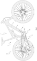
- Fig. 1 shows a schematic outline of a mountain bike with an electric bicycle drive unit DU with cycloidal gear CG according to the present disclosure in a schematic, drive-side side view.
- the mountain bike has a main bicycle frame 1 with a sprung rear frame 2.
- the electric bicycle drive unit DU comprises an energy storage device ES, which is arranged, for example, in a down tube TL of the main frame 1.
- the drive train TP of the mountain bike comprises, in addition to the drive unit DU, a chain wheel RC, a rear derailleur RD, a multiple pinion cassette CS and a drive chain CN.
- the drive unit DU is designed as a mid-engine, i.e. it is located in the area of the bottom bracket shaft SB. In this case, the bottom bracket shaft SB is included in the drive unit DU.
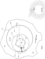
- Fig. 2 shows a cycloidal disk device DC1 of the cycloidal gear CG of the drive unit DU according to Fig. 1 . It also contains Fig. 2 two partially shown counter-cycloid devices OC1, OC2 in the form of roller sets with housing rollers RH and output rollers RO (fixed to a housing tube TH of the drive unit DU), as well as a drive shaft device DSD with a substantially cylindrically designed eccentric arrangement AE with an eccentric center axis EA of the cylinder surface of the eccentric arrangement AE.
- the cycloidal disk device DC1, DC2 which is preferably made of aluminum for reasons of weight, is mounted in this embodiment by means of a ball bearing BC on the eccentric arrangement AE of the drive shaft device DSD in such a way that a drive rotation MI of the drive shaft device DSD about the drive shaft axis AD, in conjunction with a drive contact between a cycloidal contour PC1 of the cycloidal disk device DC1, DC2 with counter contours PO1 of the housing rollers RH in contact areas CD 1, leads to an eccentric cycloidal Rolling movement MC of the cycloidal disk device DC1, DC2 relative to the roller sets RH, RO.
- This eccentric-cycloidal rolling movement MC of the cycloid disk device DC1, DC2 has an eccentric-circular movement component which corresponds to the drive shaft speed and the eccentric-circular movement of the central axis of the eccentric arrangement AE around the drive shaft axis AD, as well as a centric-circular movement component around the drive shaft axis AD slowed down according to the transmission ratio of the cycloid gear CG.
- the cycloid disk device DC1, DC2 rotates once around its own axis, which coincides with the center axis EA of the cylinder surface of the eccentric arrangement AE, when the drive shaft device DSD and thus the eccentric arrangement AE have performed 24 rotations.
- This slow rotation of the cycloid disk device DC1, DC2 around its own axis EA is transmitted to the output rollers RO by means of drive contact in contact areas CD2, with the essentially cylindrical inner cycloid contours PC2 of the cycloid disk device DC1, DC2 simultaneously rolling cycloidally on the surfaces of the output rollers RO.
- the eccentric-cycloidal rolling movement MC of the cycloidal disk device DC1, DC2 is again converted into an output rotational movement concentric with the drive shaft axis AD of the drive shaft device DSD.
- MO which is communicated to an output flange OF of the cycloidal gear CG.
- normal forces FN1, FN2 are transmitted between the housing rollers RH or the output rollers RO and the respective cycloid contours PC1, PC2, whereby the respective direction of the respective normal force FN1, FN2 is naturally perpendicular to the respective instantaneous contact surface at the contact point CP between the respective roller contour PO1, PO2 and the respective cycloid contour PC1, PC2.
- the force components of the normal forces FN 1 running in the radial direction of the cycloidal gear CG i.e. the radial forces FR1, FR2, transmit according to Fig. 2 and Fig. 2A no effective torque and therefore no drive power. Rather, the radial forces FR1, FR2 only lead to tension in the cycloidal gear CG.
- the cycloidal gear CG according to the present disclosure is intended for use in an electric auxiliary drive of a bicycle, in which, conversely, aspects such as positioning accuracy, repeatability and torque transmission in both directions play practically no role. Rather, the focus in this application is on maximizing efficiency and service life while simultaneously minimizing mass, noise and weight of the cycloidal gear CG.
- the cycloidal toothing arrangements CT1 and CT2 have a recessed free-cut contour PR1, PR2 compared to the contour PC1, PC2 along a free-cut area AC1, AC2 which is located outside the load flank sub-area AL1, AL2 of the respective contour PC1 and PC2 of the respective toothing arrangement CT1 and CT2 which is mainly involved in the power transmission.
- Fig. 3 shows the free cut contour PR1 in the area of the cycloidal tooth arrangement CT1, i.e. on the outer circumference of the cycloidal disk device DC1 according to Fig. 2
- Fig. 4 the free cut contour PR2 in the area of the cycloidal toothing arrangement CT2, i.e. at the essentially cylindrical inner cycloidal contours PC2.
- a distinctly recessed free-cut contour PR1 can be present, particularly in the head areas of the wave-shaped toothing WCT of the outer contour of the cycloid disk device CT1, since in these areas in particular no drive power is actually transmitted, as shown above with reference to Fig. 2 and Fig. 2A explained.
- Test-proven and preferred values for the degree of recess PRS of the free-cut contour PR1 are between 0.05 mm and 0.2 mm, preferably in the order of 0.1 mm, with an exemplary outer diameter of the housing tube TH of the cycloidal gear CG of 100 mm.
- a cycloidal transmission CG is obtained which can be produced cost-effectively and enables a high efficiency in power transmission and at the same time a long service life in a minimal installation space with minimal weight.
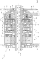
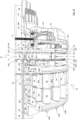
- Fig. 5 shows an electric bicycle drive unit DU with a cycloidal gear CG according to Fig. 2 to 4 in longitudinal section, while the drive unit DU in Fig. 6 (without housing tube TH) is shown in a partially sectioned oblique view.
- Fig. 6A shows the drive unit with housing tube TH.
- a summary of Fig. 5 to 7 illustrates the essential assemblies and components of the drive unit DU, including an electric motor device MD with a motor rotor device AR and a motor stator device SD, the cycloidal gear CG with two cycloidal disk devices DC1 and DC2, an axial freewheel device FA, electronic devices AP1 and AP2 and a sensor arrangement with sensor devices and their sensor elements SSP, STM and TS.
- FIG. 5 and Fig. 6 also illustrates the space-saving arrangement of the assemblies and components of the drive unit DU, which fill the installation space available within the housing TH, CHL, CHR almost completely.
- This is achieved in particular by the axial freewheel device FA (see Fig. 6 , Fig. 9 / 9A and Fig. 10 ), the Electronic device AP1 with the entire sensor electronics of all three sensor devices (cf. Fig. 7 and 8 ) and the speed sensor device STM, TE (cf. Fig. 6 and Fig. 7 ) made significant contributions.
- Fig. 5 and Fig. 6 also show a special shape of the cycloidal disk devices DC1 and DC2.
- the cycloidal disk devices are wider in the axial direction in the area of contact with the housing rollers RH than in the area of contact with the driven rollers RO. This takes into account the fact that in the area of contact of the cycloidal disk devices with the housing rollers RH, a higher surface pressure tends to occur due to the convex contact surfaces on both sides than in the area of contact of the cycloidal disk devices with the driven rollers RO, where a concave-convex contact situation exists, such as Fig. 2 to 4 can be clearly seen.
- the cycloid disk devices are correspondingly wider on their outer circumference than in the radially inner area of contact with the output rollers RO. This is particularly advantageous when the cycloid disks are made of light metal, for example aluminum, which has a lower hardness than steel, even in the contact areas CD1, CD2 with the counter cycloid devices OC1, OC2.
- the gear unit CG is completely separated from the other components of the drive unit DU by the two gear walls WGL and WGR as well as by the two rotor bearings BRL, BRR and the output bearings BOL, BOR, in particular is at least liquid-tight. This enables an optimal and permanent supply of the transmission device CG with the corresponding transmission lubricant, without the lubricant escaping from the transmission device CG and impairing the function of the other components, in particular the motor device MD, the sensor devices and the electronic devices AP1 and AP2.
- the complete separation of the gear unit CG from the other components of the drive unit DU is made possible in particular by the fact that the rotor shaft SR is mounted exclusively in the cycloidal gear CG, wherein the rotor device AR is arranged on the rotor shaft SR in the region of a flying end of the rotor shaft SR, and by the fact that the torque is output from the gear unit CG by means of an output flange OF, which is mounted by means of a differential rotor bearing BRD between the output bearing BOR and the right rotor bearing BRR.
- Such a differential rotor bearing BRD with the arrangement of the rotor device AR on a flying end of the rotor shaft SR can in principle also be realized when using a cycloidal gear CG according to the state of the art in a bicycle drive unit DU, and also when using other types of gear such as planetary gears.
- Fig. 5 also shows the main power flows TRL, TRR, TM 1 and TM2 through the drive unit DU.
- TRL and TRR are the power flows exerted by the driver via the pedal cranks PD (cf. Fig. 1 ) in the drive unit DU introduced left-hand or right-hand driver torques TRL, TRR, which are combined via a sprag freewheel FS and are introduced there in a radial direction from the bottom bracket shaft SB into the output shaft SO.
- TRL, TRR left-hand or right-hand driver torques
- TRR which are combined via a sprag freewheel FS and are introduced there in a radial direction from the bottom bracket shaft SB into the output shaft SO.
- the deformation element ED is in the form of a sleeve with a collar and consists of a magnetostrictive active alloy, for example containing nickel or cobalt.
- a magnetostrictive active alloy for example containing nickel or cobalt.
- TRR passed through the sprag freewheel FS
- the output shaft SO in the area of the sprag freewheel FS experiences a radial expansion through the sprag freewheel FS, which is communicated to the deformation element ED, which is pressed onto the output shaft SO, for example.
- Due to the radial expansion of the deformation element ED its magnetic or magnetostrictive properties change. This change can be measured using a torque sensor TS (see also Fig. 6 and 7 as well as Fig. 8 and 10 ) without contact.
- the axial freewheel device FA is characterized in particular by the fact that the power flow coming from the transmission device CG, i.e. the transmission torque TM2, is guided by means of the coupling elements DR, CL and DO in the axial direction, relative to the bottom bracket shaft SB, through the axial freewheel device FA.
- the coupling elements DR, CL and DO are a ratchet disk DR, a claw ring CL that can be moved axially along the direction MA and an output claw disk DO.
- the axial freewheel device FA is essentially flat and disc-shaped, with the engine or transmission torque TM2 being passed through the axial freewheel device FA in a radially far outer area.
- FIG. 18 once again shows which claw disc DO, claw ring CL and ratchet disc DR as well as the pawl-side components of a primary freewheel FP of the axial freewheel device FA are shown.
- the illustration according to Fig. 18 Although it comes from the further embodiment described below according to Fig. 13 to 21 .
- the in Fig. 18 However, the assemblies or components of the axial freewheel device FA shown correspond, at least in terms of their functions, to the axial freewheel device FA of the bicycle drive unit according to Fig. 1 to 11 agree.
- Fig. 18 also shows how in the further embodiment according to Fig. 13 to 21 the preferably metallic output disk DA of the axial freewheel device FA is connected to the output claw disk DO by means of driver projections DP and shape-corresponding engagement receptacles SE.
- the ratchet disk driver DDR is mounted on the ratchet disk DR by means of driver projections DP and corresponding engagement recesses SE (not visible in Fig. 18 , see however Fig. 9 or Fig. 16 ) is connected to the ratchet disc DR.
- the visible driving gears TD1 and TD2 connect the output disk DA with the output shaft SO and the ratchet disk driver DDR with the output flange OF of the gear unit CG (cf. Fig. 3 ).
- At least one of the coupling elements DR, CL, DO of the axial freewheel device FA preferably several or all coupling elements DR, CL, DO, consists essentially of a polymer material, in particular in the areas of the claws DMC and DOC, recesses or openings DRC and DMT, i.e. in the area of the toothing arrangement DMC, DOC, DRC, DMT formed thereby.
- This allows a particularly free shaping and a very cost-effective production of the coupling elements DR, CL or DO.
- weight is saved in this way, and the axial freewheel device FA is particularly quiet due to the elasticity and damping properties of the polymer material.
- the axial freewheel device FA shown is also an actively controlled axial freewheel device in which the mutual engagement of the coupling elements DR, CL, DO is actively controlled by means of a control device RDD, RDC, DMN, FPP depending on the direction of rotation.
- the axial freewheel device FA comprises a primary freewheel FP with a ratchet toothing RDR and with primary freewheel pawls FPP.
- the freewheel pawls FPP are arranged pivotably in corresponding collar recesses CO in a collar projection PT of the ratchet disk DR.
- the claw ring CL of the axial freewheel device FA which can be moved in the axial direction MA, is in a starting position on the right-hand side in relation to the figures (cf. Fig. 5 , 6 and 9 ).
- motor torque TM 1 flows through the gear device CG and from there as gear torque TM2 through the output flange OF of the gear device CG via the preferably metallic ratchet disk driver DDR into the ratchet disk DR and sets it in rotation (cf. Fig. 5 , 6 and 9 ).
- the primary freewheel pawls FPP are connected in rotation with the ratchet disk DR (see Fig. 9 ) is then used to drive the claw ring ratchet driver RDD (see Fig. 9/9A ) rotationally clockwise (relative to the Viewing direction from the right according to Fig. 1 ).
- the ratchet disk DR on the engine or transmission side is overtaken by the claw disk DO on the driver or output side. Since the claw disk DO and claw ring CL are largely firmly coupled to one another in terms of rotation due to the positive penetration of the claw disk claws DOC through the claw ring openings DMT, the ratchet disk DR on the engine or transmission side is also overtaken by the claw ring CL. Due to the claw ring claws DMC being beveled on the non-load flank side, the claw ring CL is thereby axially displaced to the right as shown in the drawing (MA) and thus disengages from the ratchet disk DR.
- MA shown in the drawing
- the effect of the inclined cams RDC of the ratchet driver RDD also contributes to the axial movement of the claw ring CL, which are held in the inclined grooves DMN of the claw ring CL by the claw ring return springs SRC.
- the spring force of the claw ring return springs SRC through the interaction of the inclined cams RDC and the inclined grooves DMN, leads to the continuation of the movement MA of the claw ring CL to the right as shown in the drawing (see. Fig. 9 , 10 and 18 ) until the claw ring CL comes into contact with the claw disc DO (cf. Fig. 5 and 6 ).
- the FA axial freewheel device can also be implemented when using a cycloidal gear CG in accordance with the state of the art in a bicycle drive unit DU, and also when using other types of gear such as planetary gears.
- the FA axial freewheel device is also suitable for other applications where an efficient, weight-saving and low-noise freewheel is required, for example for bicycle rear wheel hubs.
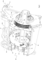
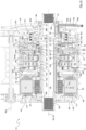
- Fig. 7 shows, especially in conjunction with Fig. 5 , Fig. 6 and Fig. 10 , the special arrangement of the disc-shaped speedometer element TE and the associated speed sensor element STM.
- the speedometer element TE is mounted by means of a speedometer driver DT (cf. Fig. 5 to 7 ) is non-rotatably connected to the bottom bracket shaft SB.
- the tachometer element TE is located inside the axial freewheel device FA, whereby the tachometer element TE and the associated speed sensor element STM are arranged on opposite sides of the output disk DA through which the transmission torque TM2 flows, which can functionally be regarded as the wall of an area or section of the output shaft SO.
- the output disk DA is preferably made of aluminum, while the speedometer element TE is preferably made of steel.
- the speed of the speedometer element TE whose toothed shape TDT clearly shows Fig. 7 This can be done reliably, for example by means of a speed sensor element STM based on magnetic field detection, without being disturbed by the presence of the output disk DA or by its possible rotation.
- This special arrangement of the tachometer element TE within the axial freewheel device FA and on the side of the wall DA of an output shaft section through which the transmission torque flows, opposite the speed sensor element STM, allows on the one hand the particularly space-saving arrangement of the components of the drive unit DU, in particular the axial freewheel device FA, and on the other hand the combination preferably of all three sensor devices 1. speed sensor device TMS with speed sensor element STM, 2. torque sensor device with torque sensor element CC, TS and 3. speed sensor device with speed sensor element SSP of the drive unit DU in the area of a single electronic device AP1.
- the special arrangement of the speedometer element TE within the axial freewheel device FA and on the side of the wall DA of an output shaft section through which the transmission torque flows, opposite the speed sensor element STM, can in principle also be implemented when using a cycloidal transmission CG according to the state of the art in a bicycle drive unit DU, and also when using other transmission types such as planetary transmissions.
- the speed sensor element SSP is in Fig. 7 and Fig. 8
- the speed sensor element SSP is used to determine the speed of the rear wheel WB of the bicycle (cf. Fig. 1 ) by means of a magnet arranged in the area of the rim of the wheel WB or, for example, on an air valve of the rear wheel WB.
- a magnetic flux concentrator DF is arranged adjacent to the speed sensor element SSP. This increases the sensitivity of the speed sensor element SSP and thus the reliability of determining the speed of the bicycle.
- a spacer element preferably made of spring steel, in the form of a roller thrust ring RR, which is arranged between the housing rollers RH and the right-hand gearbox wall WGR. Since the housing rollers RH have a slight tendency to cling to the right of the gearbox wall WGR as shown in the drawing, due to the slight elastic-rotary twisting of the cycloidal gear CG when subjected to the motor torque TM 1, the roller thrust ring RR protects the gearbox wall WGR, preferably made of aluminum, from wear and from chip formation, which is particularly harmful to the gearbox.
- the roller thrust ring RR does not lie flat against the right-hand gearbox wall WGR, but is supported by web-shaped axial projections PA of the gearbox wall WGR, which run in the radial direction and are located at an angle in the circumferential direction between the housing rollers RH, in such a way that an elastically springy preload acting in the axial direction on the housing rollers RH is produced.
- Fig. 8 shows again the electronic device AP1, which preferably comprises a circular ring-shaped circuit board on which all electronic assemblies and electronic components of all three sensor devices are arranged. Also visible in Fig. 8 another electronic device AP2, whose circuit board is also designed in the shape of a circular ring segment The circuit board of the electronic device AP2 can carry all electronic assemblies and electronic components required for the direct control of the motor device MD, for example also the power electronics required for this purpose.
- FIG. 8 The drive recesses HDT arranged in the housing tube TH are marked.
- Fig. 11 shows a cycloidal gear CG known under the name “Compur gear”, and Figure 12 another cycloidal gear CG known under the name “Cyclo-Acbar gear”.
- the entire teaching according to the present disclosure is also applicable to these cycloidal gear CG types.
- Fig. 13 to 21 show a further embodiment of a cycloidal transmission CG and a further embodiment of a bicycle drive unit DU, wherein the representations according to Fig. 13 to 21 essentially as presented in accordance with Fig. 5 to 7 and 9 to 11 are equivalent to.
- Cycloidal gear CG or drive unit DU according to Fig. 13 to 21 In terms of function and arrangement of the included assemblies or components, they largely correspond to the cycloidal gear CG or the drive unit DU according to Fig. 5 to 7 and 9 to 11 but are functionally optimized and structurally refined compared to the latter.
- Fig. 8 the first embodiment of the bicycle drive unit according to Fig. 1 to 10 shows, basic properties and functions of the with regard to Fig. 8
- the components and assemblies described also apply analogously to the further embodiment of the bicycle drive unit according to Fig. 13 to 21 .
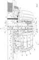
- Fig. 13 shows another embodiment of an electric bicycle drive unit DU with a cycloidal gear CG according to Fig. 2 to 4 in longitudinal section, while the drive unit DU in Fig. 14 (without housing tube TH) is shown in a partially sectioned oblique view.
- Fig. 14A shows the drive unit with housing tube TH.
- FIG. 13 to 15 illustrates the essential assemblies and components of the drive unit DU, including an electric motor device MD with a motor rotor device AR and a motor stator device SD, the cycloidal gear CG with two cycloidal disk devices DC1 and DC2, an axial freewheel device FA, electronic devices AP1 and AP2 and a sensor arrangement with sensor devices and their sensor elements SSP, STM and TS.
- the rotor device AR comprises in particular a rotor lamination package according to Fig. 13 and 14 comprising the rotor core CR and permanent magnets MP, which are held, for example, in a form-fitting manner by the rotor core CR (see also Fig. 5 , 6 and 8 ).
- the stator device SD comprises in particular stator end plates PE, which in the embodiment according to Fig. 13 to 21 composed of a number of stator coil holders BOS (see Fig. 14 ), each of which has a stator winding CST with stator connection wires WS on its outer circumference, and a stator tooth ST in its interior (in Fig. 14 not shown, but see Fig. 5 , 6 , 8 and 13 ).
- FIG. 14 A summary of Fig. 13 and Fig. 14 also illustrates the space-saving arrangement of the assemblies and components of the drive unit DU, which fill the installation space available within the housing TH, CHL, CHR almost completely. This is achieved in particular by the axial freewheel device FA (see Fig. 14 , Fig. 16 / 16A , Fig. 17 and 18 ), the electronic device AP1 with the entire sensor electronics of all three sensor devices (cf. Fig. 8 and 15 ) and the speed sensor device STM, TE (cf. Fig. 14 and Fig. 15 ) made significant contributions.
- the axial freewheel device FA see Fig. 14 , Fig. 16 / 16A , Fig. 17 and 18
- the electronic device AP1 with the entire sensor electronics of all three sensor devices (cf. Fig. 8 and 15 ) and the speed sensor device STM, TE (cf. Fig. 14 and Fig. 15 ) made significant contributions.
- Fig. 13 and Fig. 14 also show a special shape of the cycloidal disk devices DC1 and DC2.
- the cycloidal disk devices are wider in the axial direction in the area of contact with the housing rollers RH than in the area of contact with the driven rollers RO. This takes into account the fact that in the area of contact of the cycloidal disk devices with the housing rollers RH, a higher surface pressure tends to occur due to the convex contact surfaces on both sides than in the area of contact of the cycloidal disk devices with the driven rollers RO, where a concave-convex contact situation exists, such as Fig.
- the cycloid disk devices are correspondingly wider on their outer circumference than in the radially inner area of contact with the output rollers RO. This is particularly advantageous when the cycloid disks are made of light metal, for example aluminum, which has a Steel has lower hardness also in the contact areas CD1, CD2 with the counter cycloid devices OC1, OC2.
- the gear unit CG is completely sealed off from the other components of the drive unit DU by the two gear walls WGL and WGR as well as by the two rotor bearings BRL, BRR and the output bearings BOL, BOR, in particular it is sealed off at least in a liquid-tight manner.
- This enables the gear unit CG to be supplied with the appropriate gear lubricant in an optimal and permanent manner without the lubricant escaping from the gear unit CG and impairing the function of the other components, in particular the motor unit MD, the sensor devices and the electronic devices AP1 and AP2.
- thin or at least relatively low-viscosity or gel-like lubricant can advantageously be used to lubricate the gear unit, which, compared to conventional, high-viscosity lubricants such as lubricating grease, enables better distribution of the lubricant and thus more thorough lubrication and, at the same time, better cooling of the rolling surfaces of the cycloidal gear unit CG.
- the complete separation of the gear unit CG from the other components of the drive unit DU is made possible in particular by the fact that the rotor shaft SR is mounted exclusively in the cycloidal gear CG, whereby the rotor unit AR is arranged in the area of a flying end of the rotor shaft SR on the rotor shaft SR (drawing-related left in Fig. 5 to 10 and Fig. 13 to 17 ), and in that the torque is output from the transmission device CG by means of an output flange OF, which is mounted by means of a differential rotor bearing BRD between the output bearing BOR and the right rotor bearing BRR.
- Such a differential rotor bearing BRD with the arrangement of the rotor device AR on a flying end of the rotor shaft SR can in principle also be realized when using a cycloidal gear CG according to the state of the art in a bicycle drive unit DU, and also when using other types of gear such as planetary gears.
- Fig. 13 shows Fig. 13 also the arrangement and fastening of the cycloidal gear CG in the housing tube TH. It can be seen that the left-hand gear wall WGL is pushed or pressed into the housing tube TH from the right as per the drawing up to an axial stop SAE. The right-hand gear wall WGR is also pushed or pressed into the housing tube TH from the right.
- the right-hand side gearbox wall WGR is fixed by a right-hand gearbox seal WSR, the shape of which is Fig. 14 and 17 is clearly visible.
- the right-hand gearbox seal WSR forms a press fit FP when the right-hand gearbox wall WGR is pressed into the housing tube TH (see Fig. 13 ) between the right-hand gearbox wall WGR and the housing tube TH.
- the right-hand gearbox seal WSR forms a locking attachment between the gearbox wall WGR and the housing tube TH.
- Fig. 13 recognizable bearing spacers SBL, SBR (see also Fig. 5 , 6 , 10 , 14 and 17 ) enable a closed power flow through the rotor shaft SR, rotor carrier sleeve SCR (cf. Fig. 14 ), left rotor bearing BRL, left bearing spacer SBL, eccentric arrangement AE, right bearing spacer SBR, right rotor bearing BRR and from there back to the rotor shaft SR.
- these components are axially clamped against each other and are also firmly connected to each other in rotation by the frictional forces that arise.
- the recognizable components of the rotor shaft SR and the eccentric arrangement AE together form the drive shaft device DSD (see also Fig. 5 , 6 and 14 ).
- Fig. 13 also shows the main power flows TRL, TRR, TM1 and TM2 through the drive unit DU.
- TRL and TRR are the power flows exerted by the driver via the pedal cranks PD (cf. Fig. 1 ) left-hand and right-hand driver torques TRL, TRR introduced into the drive unit DU, which are combined via a sprag freewheel FS and are introduced there in a radial direction from the bottom bracket shaft SB into the output shaft SO.
- the deformation element ED is in the form of a sleeve with a collar and consists of a magnetostrictive active alloy, for example containing nickel or cobalt.
- a magnetostrictive active alloy for example containing nickel or cobalt.
- TRR passed through the sprag freewheel FS
- the output shaft SO in the area of the sprag freewheel FS experiences a radial expansion through the sprag freewheel FS, which is communicated to the deformation element ED, which is pressed onto the output shaft SO, for example.
- Due to the radial expansion of the deformation element ED its magnetic or magnetostrictive properties change. This change can be measured using a torque sensor TS (see also Fig. 8 , 14 , 15 and 17 ) without contact.
- the bottom bracket shaft SB in the embodiment according to Fig. 13 to 21 a radial stiffening bar RRB.
- the radial stiffening bar RRB prevents the wall of the bottom bracket shaft SB from deforming radially inwards in the area of the sprag freewheel FS when subjected to rider torques TRL, TRR, and also enables a reduction in the wall thickness of the bottom bracket shaft SB, thus saving material and weight.
- the axial freewheel device FA is characterized in particular by the fact that the torque transmitted from the transmission device CG, via the output rollers RO and output roller axes ROP (cf. Fig. 2 , 5 , 6 , 9 , 13 , 14 and 17 ) and output roller axle mounts ROR (cf. Fig. 9 and 16 ), i.e. the transmission torque TM2, by means of the coupling elements DR, CL and DO in the axial direction, relative to the bottom bracket shaft SB, through the axial freewheel device FA.
- the coupling elements DR, CL and DO are a ratchet disk DR, a claw ring CL that can be moved axially along the direction MA and an output claw disk DO.
- the axial freewheel device FA is essentially flat and disc-shaped, with the engine or transmission torque TM2 being passed through the axial freewheel device FA in a radially far outer area.
- At least one of the coupling elements DR, CL, DO of the axial freewheel device FA preferably several or all coupling elements DR, CL, DO, consists essentially of a polymer material, in particular in the areas of the claws DMC and DOC, recesses or openings DRC and DMT, i.e. in the area of the toothing arrangement DMC, DOC, DRC, DMT formed thereby.
- This allows a particularly free shaping and a very cost-effective production of the coupling elements DR, CL or DO.
- weight is saved in this way, and the axial freewheel device FA is particularly quiet due to the elasticity and damping properties of the polymer material.
- the axial freewheel device FA shown is also an actively controlled axial freewheel device in which the mutual engagement of the coupling elements DR, CL, DO is actively controlled by means of a control device RDD, RDC, DMN, FPP depending on the direction of rotation.
- the axial freewheel device FA comprises a primary freewheel FP with a ratchet toothing RDR and with primary freewheel pawls FPP.
- the freewheel pawls FPP are arranged pivotably in corresponding collar recesses CO in a collar projection PT of the ratchet disk DR.
- the claw ring CL of the axial freewheel device FA which can be moved in the axial direction MA, is in a starting position on the right-hand side in relation to the figures (cf. Fig. 13 , 14 and 16 ).
- motor torque TM 1 flows through the gear device CG and from there as gear torque TM2 through the output flange OF of the gear device CG via the preferably metallic ratchet disk driver DDR into the ratchet disk DR and sets it in rotation (cf. Fig. 13 , 14 and 16 to 18 ).
- the visualization of the power flow of the engine torque TM1 as a zigzag line through the gear unit CG in Fig. 13 and Fig. 5 is to be understood as merely a symbolic simplification of the actual power flow.
- the actual power flow through the gear unit CG is Fig. 2 to 4A and explained in detail in the corresponding figure description.
- the primary freewheel pawls FPP are rotatably connected to the ratchet disk DR (see Fig. 16 and 18 ) is then used to drive the claw ring ratchet driver RDD (see Fig. 16/ 16A ) rotationally clockwise (relative to the viewing direction from the right according to Fig. 1 ).
- the axial freewheel device FA according to Fig. 16 to 18 the further embodiment of a bicycle drive unit according to Fig. 1 to 4 and 13 to 21 differs from the axial freewheel device FA according to Fig. 16 and 17 the first embodiment of a bicycle drive unit according to Fig. 1 to 10 , in addition to various design refinements, in particular through a finer-toothed design of the respective teeth of the ratchet disc DR, claw ring CL and claw disc DO.
- This finer-toothed design allows either higher torques to be transmitted via the axial freewheel device FA, or lower loads to be achieved per claw DMC, DOC or per claw disc opening DMT and ratchet disc recess DRC.
- Respective overview of Fig. 17 and Fig. 10 or from Fig. 16 and Fig. 9 also illustrates the different tooth shapes of the claws DMC and DOC of the claw ring CL and claw disk DO between the first and the further embodiment, as well as the different geometries of the claw disk openings DMT and ratchet disk recesses DRC.
- the claws DMC or DOC as well as the openings or recesses DMT and DRC are less wedge-shaped and less inclined in the direction of rotation RM0 to RM5, which supports an even more reliable switching behavior of the axial freewheel device FA in all driving situations and torque loads that occur in practice.
- the further embodiment according to Fig. 16 / 6A is particularly in terms of reliability, torque transmission, noise and rigidity the ratchet toothing RDR and the primary freewheel pawls FPP.
- the ratchet disk DR on the engine or transmission side is overtaken by the claw disk DO on the driver or output side. Since the claw disk DO and claw ring CL are largely firmly coupled to one another in terms of rotation due to the positive penetration of the claw disk claws DOC through the claw ring openings DMT, the ratchet disk DR on the engine or transmission side is also overtaken by the claw ring CL. Due to the claw ring claws DMC being beveled on the non-load flank side, the claw ring CL is thereby axially displaced to the right as shown in the drawing (MA) and thus disengages from the ratchet disk DR.
- MA shown in the drawing
- the effect of the inclined cams RDC of the ratchet driver RDD also contributes to the axial movement of the claw ring CL, which are held in the inclined grooves DMN of the claw ring CL by the claw ring return springs SRC.
- the spring force of the claw ring return springs SRC through the interaction of the inclined cams RDC and the inclined grooves DMN, leads to the continuation of the movement MA of the claw ring CL to the right as shown in the drawing (see. Fig. 16 to 18 ) until the claw ring CL comes into contact with the claw disc DO (cf. Fig. 13 and 14 ).
- the FA axial freewheel device can also be implemented when using a cycloidal gear CG in accordance with the state of the art in a bicycle drive unit DU, and also when using other types of gear such as planetary gears.
- the FA axial freewheel device is also suitable for other applications where an efficient, weight-saving and low-noise freewheel is required, for example for bicycle rear wheel hubs.
- Fig. 15 shows, especially in conjunction with Fig. 13 , Fig. 14 and Fig. 17 , the special arrangement of the disc-shaped speedometer element TE and the associated speed sensor element STM.
- the speedometer element TE is mounted by means of a speedometer driver DT (cf. Fig. 13 to 15 ) is connected to the bottom bracket shaft SB in a rotationally fixed manner.
- a speedometer disc pressure spring SCT ensures that the disc-shaped speedometer element TE, which is rotationally fixed (for example by a cam arrangement) but axially displaceable on the tachometer driver DT, comes into contact with and remains on the left-hand output shaft bearing BSL of the output shaft SO.
- the speedometer element TE is axially decoupled from the tachometer driver DT and thus from the bottom bracket shaft SB in terms of tolerance and is instead referenced to the left-hand output shaft bearing BSL and with this to the output shaft SO, which closes the tolerance chain to the circuit board of the electronic device AP1, on which the speed sensor element STM is arranged, via the right-hand output shaft bearing BSR, the right housing cover CHR and the circuit board holder HC.
- This tolerance chain ensures the most constant, minimum distance possible between the speedometer element TE and the associated speed sensor element STM, which contributes to the reliability of the speed sensor device TE, STM.
- the speedometer element TE is located inside the axial freewheel device FA, whereby The tachometer element TE and the associated speed sensor element STM are arranged on opposite sides of the output disk DA through which the transmission torque TM2 flows, which can functionally be regarded as the wall of an area or section of the output shaft SO.
- the output disk DA is preferably made of aluminum, while the speedometer element TE is preferably made of steel.
- the speed of the speedometer element TE whose toothed shape TDT clearly shows Fig. 15 This can be done reliably, for example by means of a speed sensor element STM based on magnetic field detection, without being disturbed by the presence of the output disk DA or by its possible rotation.
- This special arrangement of the tachometer element TE within the axial freewheel device FA and on the side of the wall DA of an output shaft section through which the transmission torque flows, opposite the speed sensor element STM, allows on the one hand the particularly space-saving arrangement of the components of the drive unit DU, in particular the axial freewheel device FA, and on the other hand the combination preferably of all three sensor devices 1. speed sensor device TMS with speed sensor element STM, 2. torque sensor device with torque sensor element CC, TS and 3. speed sensor device with speed sensor element SSP of the drive unit DU in the area of a single electronic device AP1.
- the special arrangement of the speedometer element TE within the axial freewheel device FA and on the side of the wall DA of an output shaft section through which the transmission torque flows, opposite the speed sensor element STM, can in principle also be implemented when using a cycloidal transmission CG according to the state of the art in a bicycle drive unit DU, and also when using other transmission types such as planetary transmissions.
- the speed sensor element STM can in particular contain several sensor elements that are arranged at a distance in particular in the circumferential direction, in relation to the speedometer element TE. In this way, not only the speed of the speedometer element TE, but also its direction of rotation can be detected, whereby the bicycle drive unit DU and any other bicycle components that are informationally connected to the bicycle drive unit DU, for example a rear derailleur RP of the bicycle drive train TP, can be controlled even more reliably in all operating states.
- the speed sensor element SSP is in Fig. 8 and Fig. 15
- the speed sensor element SSP is used to determine the speed of the rear wheel WB of the bicycle (cf. Fig. 1 ) by means of a magnet arranged in the area of the rim of the wheel WB or, for example, on an air valve of the rear wheel WB.
- a magnet arranged in the area of the rim of the wheel WB or, for example, on an air valve of the rear wheel WB.
- an additional magnetic flux concentrator DF is arranged adjacent to the speed sensor element SSP (in Fig. 15 not shown, but see Fig. 7 ). This increases the sensitivity of the speed sensor element SSP and thus the reliability of determining the speed of the bicycle.
- the antenna LED assembly ALA is arranged in a hole in the preferably metallic left-hand housing cover CHL and consists at least partially of a non-metallic material such as a polymer material.
- the non-metallic material enables wireless control communication between the drive unit DU and other components on the bicycle, for example with a rear derailleur RD (see. Fig. 1 ) or with a human machine interface arranged on the bicycle frame or on the bicycle handlebars for operating the drive unit DU or for setting operating options of the drive unit DU.
- Fig. 15 Furthermore, two fastening axes FM1, FM2 are shown, which define two frame interface axes in the area of which the drive unit DU can be connected to the bicycle frame 1 (see also Fig. 7 , 8 and 15 ).
- the rear frame interfaces I'R arranged in the area of the rear fastening axis FM1 serve to determine all degrees of freedom of movement of the drive unit DU relative to the frame of the bicycle 1, except for the degree of freedom of rotation about the rear fastening axis FM1 with the front frame interfaces I'F arranged there.
- FIG. 17 Two spacer elements in the form of two roller thrust rings RR are also visible, which are preferably made of spring steel and are arranged between the housing rollers RH and the respective gear wall WGL, WGR. Since the housing rollers RH have a slight tendency to nestle horizontally against one or both of the gear walls WGL, WGR as shown in the drawing due to unavoidable tolerances and/or due to slight elastic-rotational distortion of the cycloid gear CG when subjected to the motor torque TM 1, the roller thrust rings RR protect the gear walls WGL, WGR, which are preferably made of aluminum, from wear and from chip formation, which is particularly harmful to the gear.
- Fig. 19 shows the housing tube TH of the further embodiment according to Fig. 13 to 21 with the left-hand gear wall WGL arranged therein (cf. Fig. 5 and 6 as well as Fig. 10 , 13 , 14 and 17 ), as well as a torque flange FT to support the gearbox support torque TGS to be transmitted from the gearbox wall WGL to the housing tube TH.
- the gearbox support torque TGS is created due to the Fig. 2 to 3 apparent force components FD acting in the circumferential direction on the housing rollers RH.
- the sum of these force components FD, or the resulting gearbox support torque TGS, is introduced from the housing rollers RH via the housing roller axes RHP and via the housing roller axle mounts RHR into the left-hand gearbox wall WGL (cf. Fig. 6 , 10 and 17 ).
- the gearbox support torque TGS is transferred to the Torque flange FT and from there into the housing tube TH.
- the torque flange FT is preferably made of a vibration-damping material, particularly preferably of a corresponding polymer material. This contributes to reducing externally perceptible noises of the bicycle drive unit DU and to dampening torque peaks, which also benefits the service life of the cycloidal gear CG.
- the torque flange FT allows a more flexible design of the geometry of the drive recesses HDT on the inner circumference of the housing tube TH (cf. Fig. 8 and Fig. 13 ), which would otherwise be comparatively complex to manufacture due to the cramped conditions inside the housing tube TH, for example by broaching.
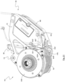
- Fig. 20 shows a bicycle drive unit with cycloidal gear, for example according to Fig. 1 to 4 and 13 to 19 , together with an energy storage device ES (cf. Fig. 1 ) in partially sectioned perspective view.
- ES energy storage device
- Fig. 21 shows the bicycle drive unit according to Fig. 20 with closed battery cover HB.
- the battery cover HB is in Fig. 20 and 21 Each is shown in section to better identify the components and their functions described below.
- the battery flap HB is pivotally connected to the right and left housing covers CHR, CHL by means of a pivot pin BSW.
- the energy storage device ES can be removed essentially as shown in the drawing below. To do this, the battery flap HB can be opened further than in Fig. 20 shown.
- the energy storage device ES has a stop bracket BST in its drawing-related lower area, which is either connected to the housing of the energy storage device ES, for example screwed or can be formed integrally with the housing of the energy storage device ES.
- the stop bracket BST of the energy storage device ES has a stop wall WST in the area of engagement recesses RE.
- the stop wall WST can be brought into contact with a correspondingly shaped counter wall CW of the housing tube TH.
- the energy storage device ES After inserting the energy storage device ES, it is essentially in the Fig. 20 shown relative position to the drive unit DU, in particular to the housing tube TH.
- a pressure projection POP which is formed integrally with the battery flap HB, for example, penetrates into the engagement recesses RE of the stop bracket BST. This presses the stop wall WST of the stop bracket BST against the corresponding counter wall CW of the housing tube TH.
- a Fig. 20 visible thrust contour PP which interacts with the drawing-related lower end of the stop wall WST of the stop bracket BST, the energy storage device ES upwards to the correct, final insertion position according to Fig. 20 pushed.
Landscapes
- Engineering & Computer Science (AREA)
- Mechanical Engineering (AREA)
- Chemical & Material Sciences (AREA)
- Combustion & Propulsion (AREA)
- General Engineering & Computer Science (AREA)
- Transportation (AREA)
- Physics & Mathematics (AREA)
- Electromagnetism (AREA)
- Thermal Sciences (AREA)
- Retarders (AREA)
- Connection Of Motors, Electrical Generators, Mechanical Devices, And The Like (AREA)
Priority Applications (3)
| Application Number | Priority Date | Filing Date | Title |
|---|---|---|---|
| CN202410800134.5A CN119178015A (zh) | 2023-06-21 | 2024-06-20 | 摆线齿轮组以及具有摆线齿轮组的自行车电驱动单元 |
| TW113122932A TW202508913A (zh) | 2023-06-21 | 2024-06-20 | 擺線齒輪組以及具有擺線齒輪組的自行車電驅動單元 |
| US18/749,280 US20250083769A1 (en) | 2023-06-21 | 2024-06-20 | Cycloidal gear and electric bicycle drive unit with cycloidal gear |
Applications Claiming Priority (3)
| Application Number | Priority Date | Filing Date | Title |
|---|---|---|---|
| DE102023116343 | 2023-06-21 | ||
| DE102023116519 | 2023-06-22 | ||
| DE102024115659.7A DE102024115659A1 (de) | 2023-06-21 | 2024-06-05 | Zykloidgetriebe sowie elektrische Fahrrad-Antriebseinheit mit Zykloidgetriebe |
Publications (1)
| Publication Number | Publication Date |
|---|---|
| EP4481232A1 true EP4481232A1 (fr) | 2024-12-25 |
Family
ID=91432614
Family Applications (1)
| Application Number | Title | Priority Date | Filing Date |
|---|---|---|---|
| EP24020183.0A Pending EP4481232A1 (fr) | 2023-06-21 | 2024-06-06 | Transmission cycloidale et unite d'entrainement electrique pour bicyclette avec transmission cycloidale |
Country Status (4)
| Country | Link |
|---|---|
| US (1) | US20250083769A1 (fr) |
| EP (1) | EP4481232A1 (fr) |
| CN (1) | CN119178015A (fr) |
| TW (1) | TW202508913A (fr) |
Citations (8)
| Publication number | Priority date | Publication date | Assignee | Title |
|---|---|---|---|---|
| CA291312A (fr) | 1929-07-16 | Konrad Braren Lorenz | Transmission par engrenages | |
| US20070042855A1 (en) * | 2005-08-19 | 2007-02-22 | Haisung Industrial Systems Co., Ltd. | External gear of planetary reduction gear having cycloid tooth and method of machining the same |
| DE102016109150A1 (de) | 2016-03-01 | 2017-09-07 | Maul Konstruktionen GmbH | Mechanisch geregelte Achsverstellung an Exzentergetrieben |
| EP3406511A1 (fr) * | 2017-05-22 | 2018-11-28 | Amprio GmbH | Pédalier de vélo électrique |
| DE102021102992A1 (de) * | 2021-02-09 | 2022-01-20 | Schaeffler Technologies AG & Co. KG | Antriebsanordnung für ein muskelbetriebenes Fahrzeug sowie Fahrzeug mit der Antriebsanordnung |
| EP3978886A1 (fr) * | 2016-11-28 | 2022-04-06 | TQ-Systems GmbH | Cellule de charge pour déterminer une force radiale agissant sur un vilebrequin |
| EP4082880A1 (fr) * | 2021-04-21 | 2022-11-02 | SRAM Deutschland GmbH | Unité d'entraînement de bicyclette électrique pourvu de dispositif de détection de couple |
| DE102022125866A1 (de) * | 2021-10-14 | 2023-04-20 | Mavic Group | Vorrichtung zur Drehmomentübertragung, Vorrichtung zur elektrischen Unterstützung und dazugehöriges Zweirad |
-
2024
- 2024-06-06 EP EP24020183.0A patent/EP4481232A1/fr active Pending
- 2024-06-20 US US18/749,280 patent/US20250083769A1/en active Pending
- 2024-06-20 CN CN202410800134.5A patent/CN119178015A/zh active Pending
- 2024-06-20 TW TW113122932A patent/TW202508913A/zh unknown
Patent Citations (8)
| Publication number | Priority date | Publication date | Assignee | Title |
|---|---|---|---|---|
| CA291312A (fr) | 1929-07-16 | Konrad Braren Lorenz | Transmission par engrenages | |
| US20070042855A1 (en) * | 2005-08-19 | 2007-02-22 | Haisung Industrial Systems Co., Ltd. | External gear of planetary reduction gear having cycloid tooth and method of machining the same |
| DE102016109150A1 (de) | 2016-03-01 | 2017-09-07 | Maul Konstruktionen GmbH | Mechanisch geregelte Achsverstellung an Exzentergetrieben |
| EP3978886A1 (fr) * | 2016-11-28 | 2022-04-06 | TQ-Systems GmbH | Cellule de charge pour déterminer une force radiale agissant sur un vilebrequin |
| EP3406511A1 (fr) * | 2017-05-22 | 2018-11-28 | Amprio GmbH | Pédalier de vélo électrique |
| DE102021102992A1 (de) * | 2021-02-09 | 2022-01-20 | Schaeffler Technologies AG & Co. KG | Antriebsanordnung für ein muskelbetriebenes Fahrzeug sowie Fahrzeug mit der Antriebsanordnung |
| EP4082880A1 (fr) * | 2021-04-21 | 2022-11-02 | SRAM Deutschland GmbH | Unité d'entraînement de bicyclette électrique pourvu de dispositif de détection de couple |
| DE102022125866A1 (de) * | 2021-10-14 | 2023-04-20 | Mavic Group | Vorrichtung zur Drehmomentübertragung, Vorrichtung zur elektrischen Unterstützung und dazugehöriges Zweirad |
Also Published As
| Publication number | Publication date |
|---|---|
| TW202508913A (zh) | 2025-03-01 |
| CN119178015A (zh) | 2024-12-24 |
| US20250083769A1 (en) | 2025-03-13 |
Similar Documents
| Publication | Publication Date | Title |
|---|---|---|
| DE112011102964B4 (de) | Radnabenmotor | |
| EP3978886B1 (fr) | Cellule de charge pour determiner une force radiale agissant sur un vilebrequin | |
| DE69901141T2 (de) | Herstellungsverfahren für Kraftfahrzeug- Ausgleichsgetriebe | |
| DE69905815T2 (de) | Gehäuse für Kraftfahrzeug- Ausgleichsgetriebe | |
| DE69617337T2 (de) | Antriebszusammenbau mit einem elektrischen Motor und einem in dem Anker dieses Motors eingebauten Differentialgetriebe | |
| WO2023285089A1 (fr) | Transmission pour un différentiel intégral, différentiel intégral et chaîne cinématique | |
| DE69020477T2 (de) | Schwungrad für einen Verbrennungsmotor. | |
| DE102011004696A1 (de) | Fahrzeugleistungsübertragungsvorrichtung | |
| EP3929469A1 (fr) | Démultiplicateur harmonique à couronne de broches | |
| DE10238023B4 (de) | Brennkraftmaschine | |
| DE112020003565T5 (de) | Kupplungsvorrichtung | |
| EP0807030B1 (fr) | Dispositif d'entrainement, en particulier des barbotins de vehicules chenilles | |
| DE102007022422A1 (de) | Doppelkupplungsanordnung mit Kolbenführungselement | |
| DE19916459A1 (de) | Starter-Generator für ein Kraftfahrzeug | |
| DE102019135018A1 (de) | Drehmomentübertragungsvorrichtung für ein Kraftfahrzeug | |
| DE112022003313T5 (de) | Kupplungsaktuator und Verfahren zu dessen Herstellung | |
| DE10043735B4 (de) | Fahrzeug-Antriebssystem | |
| DE102019100315A1 (de) | Antriebseinheit für ein Fahrzeug mit einem Elektromotor und mit einem Getriebe | |
| DE102022211901B4 (de) | Getriebe für einen Antriebsstrang eines Kraftfahrzeugs sowie Antriebsstrang mit einem solchen Getriebe | |
| DE102013109835A1 (de) | Differentialanordnung mit Kupplung | |
| EP4481232A1 (fr) | Transmission cycloidale et unite d'entrainement electrique pour bicyclette avec transmission cycloidale | |
| DE102024115659A1 (de) | Zykloidgetriebe sowie elektrische Fahrrad-Antriebseinheit mit Zykloidgetriebe | |
| EP3453104B1 (fr) | Machine électrique tournante | |
| DE102022113018B3 (de) | Getriebeanordnung mit Stufenplanetenuntersetzung, Differential und elektrisch betreibbarer Achsantriebsstrang | |
| EP0290864A2 (fr) | Machine à piston rotatif à axe interne |
Legal Events
| Date | Code | Title | Description |
|---|---|---|---|
| PUAI | Public reference made under article 153(3) epc to a published international application that has entered the european phase |
Free format text: ORIGINAL CODE: 0009012 |
|
| STAA | Information on the status of an ep patent application or granted ep patent |
Free format text: STATUS: THE APPLICATION HAS BEEN PUBLISHED |
|
| AK | Designated contracting states |
Kind code of ref document: A1 Designated state(s): AL AT BE BG CH CY CZ DE DK EE ES FI FR GB GR HR HU IE IS IT LI LT LU LV MC ME MK MT NL NO PL PT RO RS SE SI SK SM TR |
|
| STAA | Information on the status of an ep patent application or granted ep patent |
Free format text: STATUS: REQUEST FOR EXAMINATION WAS MADE |
|
| 17P | Request for examination filed |
Effective date: 20250623 |