EP4082956A1 - Porte d'ascenseur comprenant un agencement de protection de la porte - Google Patents
Porte d'ascenseur comprenant un agencement de protection de la porte Download PDFInfo
- Publication number
- EP4082956A1 EP4082956A1 EP21170847.4A EP21170847A EP4082956A1 EP 4082956 A1 EP4082956 A1 EP 4082956A1 EP 21170847 A EP21170847 A EP 21170847A EP 4082956 A1 EP4082956 A1 EP 4082956A1
- Authority
- EP
- European Patent Office
- Prior art keywords
- door
- elevator
- car
- elevator door
- contact element
- Prior art date
- Legal status (The legal status is an assumption and is not a legal conclusion. Google has not performed a legal analysis and makes no representation as to the accuracy of the status listed.)
- Withdrawn
Links
- 230000003213 activating effect Effects 0.000 claims 1
- 230000006378 damage Effects 0.000 description 6
- 208000027418 Wounds and injury Diseases 0.000 description 5
- 208000014674 injury Diseases 0.000 description 5
- 239000000428 dust Substances 0.000 description 2
- 239000000463 material Substances 0.000 description 2
- 208000025721 COVID-19 Diseases 0.000 description 1
- 241000711573 Coronaviridae Species 0.000 description 1
- 206010011906 Death Diseases 0.000 description 1
- 241001465754 Metazoa Species 0.000 description 1
- 230000004888 barrier function Effects 0.000 description 1
- 238000005452 bending Methods 0.000 description 1
- 230000006835 compression Effects 0.000 description 1
- 238000007906 compression Methods 0.000 description 1
- 230000002950 deficient Effects 0.000 description 1
- 230000001419 dependent effect Effects 0.000 description 1
- 230000003203 everyday effect Effects 0.000 description 1
- 230000003287 optical effect Effects 0.000 description 1
- 230000004083 survival effect Effects 0.000 description 1
Images



Classifications
-
- B—PERFORMING OPERATIONS; TRANSPORTING
- B66—HOISTING; LIFTING; HAULING
- B66B—ELEVATORS; ESCALATORS OR MOVING WALKWAYS
- B66B13/00—Doors, gates, or other apparatus controlling access to, or exit from, cages or lift well landings
- B66B13/24—Safety devices in passenger lifts, not otherwise provided for, for preventing trapping of passengers
- B66B13/26—Safety devices in passenger lifts, not otherwise provided for, for preventing trapping of passengers between closing doors
Definitions
- the present invention relates to a door guard arrangement for an elevator door. Furthermore, the invention relates to an elevator door or an elevator provided with such a device.
- Such elevator features may comprise e.g. functions avoiding that an elevator car is displaced as long as the car door or an associated shaft door (also called a landing door) is open, or functions avoiding that the car door may be unlocked as long as the car is outside of a landing area, etc.
- there are two different kinds of elevator doors - an inside car door being seen from inside of an elevator car and a landing door being seen from outside of the elevator car. All automatic elevator doors are usually powered by a door operator installed on the elevator car so that the car door may open both itself and a landing door which is coupled with the car door.
- the most common elevator injury is someone being struck by a closing elevator door. This is called a door strike injury or an elevator sandwiching accident, and they generally occur while somebody is entering the elevator car, the resulting injury could be severe, as the door's closing force or speed is quite high.
- the elevator doors should close safe that would make injury unlikely.
- the more serious situation is that the car begins to move when the elevator door is already closed with a clamped object which is not detected.
- An object that has been clamped means that this object cannot enter or exit through the elevator door or cannot be taken away from the elevator door.
- the elevator door is equipped with a variety of safety devices like an optical sensor. The elevator door will reopen, or the elevator car may not drive if such an accident happened.
- an elevator door comprises normally a photoelectric sensor or a so-called light curtain with multiple photodetectors and light transmitters (often infrared) along vertical direction mostly in the left and right both sides of the surface of the door.
- Multiple light beams can be formed across the door space (entrance to the elevator car) in many horizontal directions between the photodetectors and the light transmitters when the door is open. If a part of these light beams is interrupted, it will be detected as there is an obstacle (passenger or barrier) so that the door will stop closing and reverse open. For instance, it should automatically initiate the re-opening of the elevator door in the event of a person crossing the entrance during the closing movement of this door.
- these photodetectors and light transmitters are set at a fixed interval width, then an object like a rope-shaped object, e.g. a leash, often cannot be detected correctly.
- both of a mechanical protect device or a photoelectric protect device like light curtain may be rendered inoperative in the last 20 mm of door closing gap, because even though a completely closed door may inevitably left a door gap.
- the protection hence depends on how big a clamped object or obstacle is.
- the protect device is able to only detect an obstacle with a diameter of minimum 50 mm.
- the safety device is configurated to recognize the existence of an obstacle only when not one, but a part of the light beam (light transmit path) is broken, and the light curtain shall cover the opening over the distance between at least 25 mm and 1600 mm above the elevator door sill. Therefore, an object with a small diameter like a rope-shaped object is more difficult to be detected accurately while the door closing.
- an elevator door with a door guard arrangement for an elevator is provide.
- the door guard arrangement may comprise a force sensor and a safety switch, wherein the force sensor comprises a contact element.
- the force sensor is capable of being installed at the elevator door in this manner that the contact element can activate the safety switch when the contact element is operated by this object.
- the activated safety switch may generate and send a signal to a controller of the elevator for preventing or stopping a car of the elevator from moving.
- the force sensor of this kind of guard arrangement can directly contact an object clamped by the elevator door. Even a string-like object, e.g.
- a pet leash that is ignored often by a light curtain can be detected because the force sensor detecting does not rely on the size, dimension, or material of an object.
- the force sensor detecting does not rely on the size, dimension, or material of an object.
- it may provide and ensure safety for passengers, especially a door strike injury to pets can be avoided as far as possible.
- the purpose of improving safety protection for pets is achieved without incurring excessive costs.
- the contact element is equipped with a torsional spring so that the contact element may rotate and activate the safety switch when the operating force executed by the clamped object on the contact element exceeds the stiffness of the torsional spring.
- the spring may keep or hold the contact element when the contact element is contacted by the clamped object and hence rotates. And the torsional spring may also automatically pull the contact element back to its original installed position.
- the stiffness of the spring can be a bending, torsion, or compression stiffness and corresponding stiffness of the spring.
- the contact element is capable of rotating around a shaft fixed at the elevator door.
- the contact element can be installed by means of this shaft so that the contact element can act as a rotational lever.
- the shaft can be constructed as a part of the contact element or as a separate simple structural unit that is suitable for assembling with the contact element.
- the position of the shaft can be in the middle or on a side of the contact element so that the contact element is able to rotate around this shaft.
- the object operating the contact element is capable of being caused due to the car driving or moving.
- the operating force acting on the contact element depends on the movement of the object to the contact element. Normally, if the clamped object is detected by the force sensor during the elevator door closing, the door will reopen so that the elevator car will not be allowed to drive away. But if the elevator door has already closed, the elevator car may drive away from the landing floor to a destination floor. In this case, even if the clamped object is stuck between the door gap, after the car begins moving, the clamped object will be drawn by the car and moves vertically to the contact element.
- the safety switch will be activated when the object reaches the contact element.
- An elevator may comprise a car door and/or at least one shaft door.
- the shaft door normally may only close and open together with a shaft door coupled (e.g. through a mechanical interlock) with this car door.
- the elevator door can comprise a shaft door and/or a car door of the elevator. Consequently, the door guard arrangement can be installed either at a car door or a shaft door.
- an elevator door is installed in a door frame.
- the elevator door may be constructed as a side-opening slide door consisting of at least one door panel.
- Such an elevator door can be a single opening door that only has a single door panel. The door panel opens to the left or right laterally.
- the elevator door can be constructed as a telescopic door consisting of more than one door panel.
- the force sensor may be attached to the door frame of the elevator door so that the contact element of the force sensor accordingly protrudes from the door frame and across a gap between the door frame and the door panel of the elevator door when the elevator door is closed completely.
- the force sensor can be attached to the door panel.
- the safety switch can be installed freely on the same side, or on the opposite side of the force sensor in relation to the door-opening. This means that the force sensor and the safety switch can be placed on the same side or respectively on both sides of the opening of the elevator door.
- the elevator door can be constructed as a center-opening slide door consisting of at least two door panels.
- This kind of elevator door consists of two door panels that meet in the middle and slide open laterally.
- One advantage of such an elevator door is its high-efficiency operation so that the time needed to open or close the door is shorter.
- the force sensor of the door guard arrangement can be attached to one of the door panels, wherein the contact element of the force sensor protrudes from this door panel and across a gap between the two door panels when the shaft door has closed completely.
- the safety switch can be installed freely at the same door panel or the opposite door panel of the force sensor. This means that the force sensor and the safety switch can be placed on the same side or respectively on both sides of the opening of the elevator door.
- the door guard arrangement can be constructed as a device (e.g. a limit switch) integrated with the force sensor and the safety switch.
- the slide guard arrangement is able to be constructed as a group of separate components comprising the force sensor and the safety switch.
- the force sensor and the safety switch may be arranged at different place with the elevator door.
- the force sensor and the safety switch are at different door panels of an elevator door, or the fore sensor is in the door frame, and the safety switch is at the door panel. The prerequisite for this is to ensure that the force sensor may activate the safety switch.
- the elevator door consists of a car door and a shaft door at a landing place of the elevator, wherein the elevator may have more than shaft door.
- the force sensor is set at the shaft door while the safety switch is at the car door, e.g. on the internal (normally invisible) side of the shaft door and the car door.
- the achieved advantage herewith is that the safety switch is necessary to be installed only at the car door, but not at every shaft door. The total cost for an elevator that is to be equipped with a door guard arrangement may consequently be reduced.
- the safety switch can be set at the shaft door, and the force sensor is at the car door in this case.
- At least two door guard arrangements are installed at the elevator door.
- One of these devices is arranged near to or on the top of the elevator door while another one is near to or on the bottom or sill of the elevator door.
- the lower guard arrangement should be set as close as possible to the sill, as a string-like object, e.g. a pet leash is often dragged on the ground. Therefore, if a pet leash gets stuck at an elevator door in an area where the light curtain at this door is not able to detect it, no matter whether the car travels up or down, this pet leash will reach one of these guard arrangement s to activate a safety switch. It will cause the elevator to stop before the pet or its owner will suffer any harm.
- the safety switch of the door guard arrangement can be connected with the controller of the elevator via wired or wireless communication means, preferably over a network (e.g. internet or a local network like LAN), so that the signal of the safety switch can be sent to the controller.
- a network e.g. internet or a local network like LAN
- the controller can prevent the car from moving and optionally reopen the elevator door. Even if the car has begun to move or is already in moving, the controller may stop the car immediately.
- a pet-leash is clamped at an elevator door so that a pet and its owner are separated by this door, for example, the owner is inside the car, but his pet is not yet.
- an elevator door which may comprise an afore-mentioned door guard arrangement.
- an elevator which may comprise an elevator door according to the second aspect of the invention.
- the controller of the elevator is able to prevent and/or stop the car from moving after the controller has received the signal from the door guard arrangement.
- Fig. 1 shows an elevator 5 with a slide elevator door 4 which opens to left or right laterally.
- the elevator door 4 can be a shaft door or comprise a shaft door coupled with a car door, wherein the shaft door and the car door close or open simultaneously.
- the elevator door 4 comprises a light curtain with many photodetectors and light transmitters 14 arranged separately in the door frame 10 and the door panel 4a so that a multiple of light beams are formed horizontally across the door space at the entrance to the elevator car 11 when the elevator door 4 is open.
- the light beams form an invisible light net at the entrance. Just for the convenience of presentation, these light beams are illustrated in Fig.1 . If some light beams are broken during the elevator door 4 is closing, the elevator 5 or the elevator door 4 may know that there is something in the door space. The elevator door 4 will either stop closing or at first open shortly and then try to close again.
- the reliability of this light curtain is related to the number of the existing light beams. The more the number of these detectors/light transmitters 14, the more beams there are, and thus the better safety the elevator door 4 has. However, there are still many spaces and gaps existing in the net formed by the light beams, especially in the place near the door frame 10 and the door panel 4a. In case that some detectors or transmitters 14 are defective or obscured by dust so that a rope-shaped object like a leash 6 could not be detected correctly.
- the protection with the light curtain may be rendered inoperative in the last 20 mm of the door closing gap, because even though a closed elevator door 4 may be left a gap between the door panel 4a and the door frame 10. The protection hence still depends on the dimension of a clamped object 6.
- a door guard arrangement 1 is provided.
- Such a door guard arrangement 1 is represented in Fig. 2 at an elevator door 4, wherein a rear site of an elevator door with this door guard arrangement.
- the door guard arrangement 1 comprises a force sensor 2 and a safety switch 3, wherein the force sensor 2 comprises a contact element 7 equipped with a torsional spring 8, wherein the spring 8 may keep or hold the contact element 7.
- the contact element 7 thus can act as a rotational lever to rotate around a shaft 15 if a force acting on this contact element 7 exceeds the stiffness of the spring 8. After then, the torsional spring can automatically pull the contact element 7 back to its original position.
- the contact element 7 can be attached to the elevator door 4 using this shaft 15.
- the shaft 15 can be constructed as a part of the contact element 7 or as a separate unit that is suitable for assembling with the contact element 7.
- the elevator door 4 may comprise a car door and a shaft door coupled with the car door. And for some kinds of elevators, there is no car door. Consequently, the door guard arrangement 1 can be installed either at a car door or a shaft door. Furthermore, the contact element 7 can be arranged to a door panel 4a or a door frame 10 of the elevator door 4, while the safety switch 3 can be flexibly installed independently of the contact element 7. The key is that it must ensure that the contact element 7 in rotating can contact and activate the safety switch 3. This means that the force sensor 2 including the contact element 7 and the spring 8 can be placed with the safety switch 3 either together or apart on the same side or respectively on both sides of the opening of the elevator door 4. For this embodiment shown in Fig.
- the guard arrangement 1 is installed on the rear side of a shaft door or a car door which is normally not visible for passengers, wherein the contact element 7 is at the door panel 4a, and the safety switch 3 is arranged at the opposite of the contact element 7 at the door frame 10.
- the force sensor 2 is at the shaft door while the safety switch 3 is at the car door.
- the safety switch 3 it is no more necessary to set the safety switch 3 at every shaft door respectively, because the car door will be coupled with the shaft door when the car has landed on a floor. And the force sensor 2 at this shaft door and the safety switch 3 at the car door will build a guard arrangement at this moment. The same goes also for the case that safety switch 3 is at the shaft door, while fore sensor 2 is at the car door.
- the contact element 7 protrudes partially from the door panel 4a so that the contact element 7 may cross the door gap when the elevator door is closed. Therefore, the contact element 7 can be operated if an object 6 moves vertically along the door gap so that the contact element 7 may detect such an object 6 without relying on its size, dimension, or material.
- the movement of the object 6 is caused e.g. due to the car 11 moving when the elevator door 4 is closed already, wherein the clamped object 6 is drawn by the car 11.
- one door guard arrangement 1 is arranged near to (e.g. within 5 cm) or on the top of the elevator door 4, while another one is accordingly near to or on the bottom of the elevator door 4. Therefore, if a string-like object 6, e.g. a pet leash, gets stuck at an elevator door 4, no matter whether the car 11 travels up or down, this pet leash 6 will reach one of these guard arrangement s 1 so that a safety switch 3 will be activated.
- the force sensor 2 can detect the presence of the object 6 clamped by the elevator door 4 if this object 6 moves to the contact element 7, even though the object 6 is thin and soft like a pet leash which is thinner than the door gap.
- An intermediate guard arrangement (not shown) between the upper and the lower guard arrangement 1 is also considerable, in order to ensure more safety. For example, in case a pet is alone in the downwards-moving car 11 and the pet leash 6 is dropped on the ground, the car 11 can stop already when the intermediate force sensor 2 is operated by the pet leash 6. It needs no more to wait, until the leash 6 reaches the upper force sensor 2. A potential danger than may be avoided as far as possible.
- the contact element 7 will rotate and then can activate the safety switch 3. Then the activated safety switch 3 will generate a signal.
- the guard arrangement 1, particularly the safety switch 3 is connected wired or wirelessly with a controller 9 of the elevator 5, wherein the connection is preferable via a network (e.g. internet or LAN), the signal thus can be sent to the controller 9. According to this received signal, the controller 9 will prevent the car 11 from moving and optionally reopen the elevator door. Even if the car 11 is moving, the controller 9 can also stop the car 11 immediately.
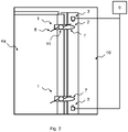
- Fig. 3 shows a front site of a slide elevator door 4 with a side-opening, wherein the grey part shows a car 11 behind this elevator door 4.
- the shaft door 4 consists of at least one door panel 4a.
- the force sensor 2 can be attached to the door panel 4a, wherein the contact element 7 partially protrudes from the door panel 4a to the door frame 10, but the contact element 7 will not obstruct the closing of the door 4.
- the safety switch 3 is placed on the opposite side of the force sensor 2, namely at the door frame 10 at a suitable distance from the contact element 7. A suitable distance is e.g. smaller than the rotating radius of the contact element 7.
- Fig. 4 shows a front site of another type of the elevator door 4 which opens and closes from the middle of the door.
- This kind of the elevator door 4 comprises two door panels 4a, 4b.
- the elevator door 4 may also consist of a shaft door and/or a car door.
- the door guard arrangement 1 can be installed at one of the door panels 4a, 4b, e.g. at the door panel 4a.
- both the force sensor 2 and the safety switch 3 can be placed on the same side of the elevator door 4, namely at the door panel 4a.
- the door guard arrangement 1 additionally can be constructed as a single device in which the force sensor 2 and the safety switch 3 are integrated.
Landscapes
- Elevator Door Apparatuses (AREA)
Priority Applications (1)
| Application Number | Priority Date | Filing Date | Title |
|---|---|---|---|
| EP21170847.4A EP4082956A1 (fr) | 2021-04-28 | 2021-04-28 | Porte d'ascenseur comprenant un agencement de protection de la porte |
Applications Claiming Priority (1)
| Application Number | Priority Date | Filing Date | Title |
|---|---|---|---|
| EP21170847.4A EP4082956A1 (fr) | 2021-04-28 | 2021-04-28 | Porte d'ascenseur comprenant un agencement de protection de la porte |
Publications (1)
| Publication Number | Publication Date |
|---|---|
| EP4082956A1 true EP4082956A1 (fr) | 2022-11-02 |
Family
ID=75728655
Family Applications (1)
| Application Number | Title | Priority Date | Filing Date |
|---|---|---|---|
| EP21170847.4A Withdrawn EP4082956A1 (fr) | 2021-04-28 | 2021-04-28 | Porte d'ascenseur comprenant un agencement de protection de la porte |
Country Status (1)
| Country | Link |
|---|---|
| EP (1) | EP4082956A1 (fr) |
Citations (3)
| Publication number | Priority date | Publication date | Assignee | Title |
|---|---|---|---|---|
| JPH0977439A (ja) * | 1995-09-18 | 1997-03-25 | Otis Elevator Co | エレベーターのドア安全装置 |
| EP2345618A1 (fr) * | 2010-01-18 | 2011-07-20 | Inventio AG | Bordure de sécurité d'une porte de cabine |
| KR101929838B1 (ko) * | 2017-07-14 | 2018-12-17 | 전남대학교산학협력단 | 애완동물의 목줄 감지 안전장치가 구비된 엘리베이터 |
-
2021
- 2021-04-28 EP EP21170847.4A patent/EP4082956A1/fr not_active Withdrawn
Patent Citations (3)
| Publication number | Priority date | Publication date | Assignee | Title |
|---|---|---|---|---|
| JPH0977439A (ja) * | 1995-09-18 | 1997-03-25 | Otis Elevator Co | エレベーターのドア安全装置 |
| EP2345618A1 (fr) * | 2010-01-18 | 2011-07-20 | Inventio AG | Bordure de sécurité d'une porte de cabine |
| KR101929838B1 (ko) * | 2017-07-14 | 2018-12-17 | 전남대학교산학협력단 | 애완동물의 목줄 감지 안전장치가 구비된 엘리베이터 |
Similar Documents
| Publication | Publication Date | Title |
|---|---|---|
| CN1251957C (zh) | 电梯门的安全装置及其运行方法 | |
| AU782199B2 (en) | Inspection opening in an elevator car | |
| JP5254566B2 (ja) | エレベータのドア装置 | |
| CN105775946B (zh) | 一种电梯控制系统及方法 | |
| JP2004527675A (ja) | カメラによって動きを管理された安全装置 | |
| CN107250478A (zh) | 控制门组件的方法、这样的一种门组件,及用于该门组件的安全装置 | |
| US11274020B2 (en) | Door operation controller | |
| JP2008169009A (ja) | エレベータ装置及びエレベータシステム | |
| KR101531701B1 (ko) | 관절형 플랫폼 스크린도어 | |
| JP2018095457A (ja) | エレベーター装置 | |
| EP4082956A1 (fr) | Porte d'ascenseur comprenant un agencement de protection de la porte | |
| JPWO2007066375A1 (ja) | エレベータのドア安全装置 | |
| US12275618B2 (en) | Shaft door with a door guard arrangement | |
| US4357998A (en) | Between landing car door safety lock | |
| KR101324093B1 (ko) | 엘리베이터 출입구의 보호장치 및 제어방법 | |
| JP2003193745A (ja) | 自動ドア | |
| JP2010058881A (ja) | エレベータのドア安全装置 | |
| CN110626929B (zh) | 电梯门系统关门再检测装置 | |
| US6615953B1 (en) | Construction hoist with optical monitoring device | |
| JP4252323B2 (ja) | エレベータの着床検出装置 | |
| HK40095972A (zh) | 具有门防护装置的竪井门 | |
| KR102120481B1 (ko) | 확장된 장애물 방지판을 가진 스크린 도어 장치 | |
| CN111032558B (zh) | 电梯的防夹手用安全装置 | |
| KR101278946B1 (ko) | 철도 승강장의 안전사고 방지 시스템 | |
| JPH08259157A (ja) | エレベーターの扉安全装置 |
Legal Events
| Date | Code | Title | Description |
|---|---|---|---|
| PUAI | Public reference made under article 153(3) epc to a published international application that has entered the european phase |
Free format text: ORIGINAL CODE: 0009012 |
|
| STAA | Information on the status of an ep patent application or granted ep patent |
Free format text: STATUS: THE APPLICATION HAS BEEN PUBLISHED |
|
| AK | Designated contracting states |
Kind code of ref document: A1 Designated state(s): AL AT BE BG CH CY CZ DE DK EE ES FI FR GB GR HR HU IE IS IT LI LT LU LV MC MK MT NL NO PL PT RO RS SE SI SK SM TR |
|
| STAA | Information on the status of an ep patent application or granted ep patent |
Free format text: STATUS: THE APPLICATION HAS BEEN WITHDRAWN |
|
| 18W | Application withdrawn |
Effective date: 20221108 |