EP4083346A1 - Dispositif de support pour une pompe à béton sur camion - Google Patents
Dispositif de support pour une pompe à béton sur camion Download PDFInfo
- Publication number
- EP4083346A1 EP4083346A1 EP22165017.9A EP22165017A EP4083346A1 EP 4083346 A1 EP4083346 A1 EP 4083346A1 EP 22165017 A EP22165017 A EP 22165017A EP 4083346 A1 EP4083346 A1 EP 4083346A1
- Authority
- EP
- European Patent Office
- Prior art keywords
- pivoting
- leg
- frame
- section
- legs
- Prior art date
- Legal status (The legal status is an assumption and is not a legal conclusion. Google has not performed a legal analysis and makes no representation as to the accuracy of the status listed.)
- Granted
Links
Images


Classifications
-
- E—FIXED CONSTRUCTIONS
- E04—BUILDING
- E04G—SCAFFOLDING; FORMS; SHUTTERING; BUILDING IMPLEMENTS OR AIDS, OR THEIR USE; HANDLING BUILDING MATERIALS ON THE SITE; REPAIRING, BREAKING-UP OR OTHER WORK ON EXISTING BUILDINGS
- E04G21/00—Preparing, conveying, or working-up building materials or building elements in situ; Other devices or measures for constructional work
- E04G21/02—Conveying or working-up concrete or similar masses able to be heaped or cast
- E04G21/04—Devices for both conveying and distributing
- E04G21/0418—Devices for both conveying and distributing with distribution hose
- E04G21/0436—Devices for both conveying and distributing with distribution hose on a mobile support, e.g. truck
Definitions
- the present invention relates to a support device for a truck-mounted concrete pump according to the preamble of claim 1, a truck-mounted concrete pump with such a support device and a set with a front and a rear swivel leg.
- Truck-mounted concrete pumps known from the prior art have a support device in order to divert the loads of the placing boom and any other forces acting on the truck-mounted concrete pump into the subsoil.
- Such support devices comprise two pairs of mutually pivotable pivoting legs, which are articulated laterally to a support structure (usually the mast block or a structure connected thereto) of the truck-mounted concrete pump and have support cylinders at their ends. At least one of the swiveling legs can usually be swiveled out to the side as well as telescoped in order to achieve the required length for stable support with a compact design at the same time.
- the pivoting legs When the truck-mounted concrete pump is being driven, the pivoting legs are in a swiveled-in and telescoped state, usually behind a driver's cab of the truck-mounted concrete pump. Due to the compact design, the retracted and pivoted telescopic sections of the pivoting legs usually require space in the other pivoting leg.
- the non-telescoping pivoting legs are formed in the shape of a fork and towards the pivot axis have open recesses in which the telescopic sections of the telescoping pivoting legs can be accommodated when retracted.
- each telescoping pivoting leg has a further locking device which, during operation, prevents the pivoting legs from retracting unintentionally as a result of the forces acting on the supporting device.
- the object of the present invention is therefore to provide a simpler and more cost-effective locking device for the supporting device of generic truck-mounted concrete pumps.
- a support device for a truck-mounted concrete pump which comprises a frame and at least one front pivoting leg and at least one rear pivoting leg.
- the pivoting legs are articulated to the frame so that they can pivot relative to one another, with the front pivoting leg being designed to be telescopic.
- the front pivot leg includes a pivot portion pivotally mounted on the frame with at least one telescoping portion slidably mounted therein. The latter can be stored at least partially in a recess of the rear pivoting leg in a telescoped state.
- pivoting relative to one another to the frame is to be interpreted broadly and does not imply that the pivot axes must coincide or that the pivot legs are directly connected. It is also conceivable that both pivoting legs are linked to the frame via separate pivoting axes. In particular, the two pivoting legs can be pivoted independently of one another in the unlocked state.
- the telescopic section of the front pivoting leg includes a locking means, by means of which the telescopic section can be fixed or locked in a pivoted-in and telescoped-in position (hereinafter: first position) relative to the rear pivoting leg, and in a telescoped-out position (hereinafter: second position) relative to the Pivoting section can be determined or locked.
- first position pivoted-in and telescoped-in position
- second position telescoped-out position
- the front pivoting leg can be pivoted and/or pivotable relative to the rear pivoting leg.
- the second position can correspond to a fully or almost fully telescoped state of the front swivel leg.
- both the locking of the two pivoting legs as a whole to one another for driving operation (first position) and the locking of the telescopic section with the pivoting section (i.e. not with the rear pivoting leg) are carried out using the same locking means, which is arranged on the telescopic section and is moved with it.
- This locking means thus fulfills a dual function and takes over the tasks of the previous separate locking devices.
- one fixing means for example a locking cylinder, can be saved per pair of pivoting legs (comprising a rear and front pivoting leg), which reduces the overall weight and the costs of the supporting device.
- the two pivoting legs cannot be pivoted relative to one another and the front pivoting leg cannot be telescoped.
- the swivel legs are secured for driving on the truck-mounted concrete pump and cannot swivel out to the side.
- the front pivoting leg cannot be telescoped, but it can be pivoted with respect to the rear pivoting leg.
- the pivoting and telescopic sections are locked or locked together, while the front pivoting leg is not fixed or locked in relation to the rear pivoting leg.
- This locked second position relates to the working operation of the truck-mounted concrete pump, during which it is to be ensured that the front pivoting legs do not telescope in due to the loads that occur.
- the pivoting section and the rear pivoting leg each comprise a counter-fixing means, wherein the fixing means can be brought into engagement with the counter-fixing means of the rear swiveling leg in the first position and can be brought into engagement with the counter-fixing means of the pivoting section in the second position is.
- the counter-fixing means are in particular fixedly arranged on the rear pivoting leg and on the pivoting section of the front pivoting leg, while the fixing means moves with the telescopic section. Depending on the position of the telescopic section, it can lock with the first or the second counter-fixing means.
- the locking and counter-locking means can be bolts/projections and recesses/bores.
- the locking means can be actively actuated.
- it can be locked and/or unlocked by active actuation.
- Provision can also be made for the locking/unlocking to take place automatically, eg mediated by a spring, with corresponding overlap with one of the counter-locking means, while the unlocking/locking must be actively initiated by actuating the locking means accordingly.
- the latter is preferably a blocking cylinder which can be actuated hydraulically in particular (ie a hydraulic cylinder).
- the counter-fixing means are passive elements into which the fixing means can be inserted.
- the counter-fixing means can be designed as recesses, preferably as bores.
- the pivoting legs are articulated on the frame pivotably about a common vertical axis, preferably via a two-part pivoting pin.
- the latter may comprise upper and lower pivot pin parts which are coaxial and spaced from each other.
- the telescopic section can penetrate the pivot axis in a retracted state and be pivoted through the recess of the rear pivot leg.
- the front and rear pivoting legs can also be pivoted to the frame about two axes lying close to one another, which are also preferably realized by two-part pivoting pins. "Close to one another" can be understood in such a way that the distance between the axes is smaller than the longest part of the telescopic section that protrudes backwards beyond the pivoting section.
- the support device can comprise at least two front and two rear swivel legs.
- only one locking means can be provided for each pair of front and rear pivoting legs, which are arranged in particular on the side of the frame.
- the fixing means is located in the area of the rear end of the telescopic section, which is mounted in the first position within the rear pivoting leg.
- the end of the telescoping section In the second position, the end of the telescoping section is within the pivoting section and the locking means can be brought into overlap with a corresponding counter-locking means of the pivoting section.
- the end of the telescopic section In the first position, the end of the telescopic section is outside of the pivoting section, so that when it is pivoted in, it is within the recess of the rear pivoting leg and can be overlapped there with a corresponding counter-fixing means of the rear pivoting leg.
- the present invention also relates to a set of a front swivel leg and a rear swivel leg of a support device according to the invention. These can be mounted on a frame of a truck-mounted concrete pump. This obviously results in the same advantages and properties as for the supporting device according to the invention, which is why a repeated description is dispensed with.
- the present invention also relates to a truck-mounted concrete pump with a support device according to the invention. This obviously results in the same advantages and properties as for the support device according to the invention, which is why a repeated description is dispensed with at this point.
- the truck-mounted concrete pump comprises two pairs of a front and a rear swivel leg, which are hinged to the frame on opposite sides.
- the pivot leg pairs are pivoted about a common vertical axis to the frame, in particular via two-part pivot bolts as described above.
- the truck-mounted concrete pump includes a placing boom that can rotate about a vertical axis and is arranged on a mast bracket, with the mast bracket enclosing the frame or being connected to it.
- the distributor boom can comprise a number of segments that can be swiveled relative to one another, along which a concrete line is routed. The forces occurring during operation of the truck-mounted concrete pump are transmitted to the subsoil via the placing boom and the boom support or the frame as well as via the support device.
- the figure 1 shows an embodiment of the support device according to the invention, the pivoting legs 10, 12 of which are in the first position, in a lateral sectional view along the longitudinal axes of the pivoting legs 10, 12.
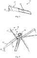
- An overall view of the supporting device with two pairs of pairs of pivoting legs 10, 12 articulated laterally to a frame 26 is in the figure 6 shown in a perspective view.
- the support device comprises a rear pivoting leg 12 which is pivotable about a vertical axis 20 on one in the figure 1 frame 26, not shown, is articulated and not telescopic, and a front swivel leg 10, which is pivoted about the same axis 20 on the frame 26 and is also telescopic (e.g. by means of a hydraulic cylinder).
- the front pivoting leg 10 comprises a pivoting section 14, which is articulated to the frame 26 and can also be referred to as a slide-out box, and a telescopic section 16 which is movably mounted therein.
- the telescopic section 16 has a support cylinder 22, which can be retracted and extended vertically, in particular hydraulically.
- the rear pivoting leg 12 has at its end spaced apart from the axis 20 such a support cylinder 22, which in the figure 1 however, is not shown (see figure 6 ).
- the telescoping portion 16 In the first position, which in the figure 1 As shown, the telescoping portion 16 is fully retracted within the pivoting portion 14 and extends rearwardly beyond the latter.
- the pivoting legs 10, 12 are aligned parallel or coaxial to one another (with respect to their longitudinal axes).
- the rear pivot leg 12 has an elongated recess 18 which is open towards the axis 20 and receives the rear part of the telescopic section 16 .
- the recess 18 is also open to the sides (the portion of the rear pivot leg 12 which has the recess 18 is therefore forked, wherein the fork depth may be less than, more than or substantially half the length of the rear pivot leg), so that the front pivoting leg 10 can in principle be pivoted relative to the rear pivoting leg 12 even in the retracted state.
- the geometry of the frame 26 is advantageously designed in such a way that the front pivoting leg 10 can be pivoted out to the side or the part of the telescopic section 16 that protrudes to the rear can be pivoted inwards (see FIG figure 6 for a possible frame shape).
- the two swivel legs 10, 12 are connected via a two-part swivel pin 24 (see figure 6 ) articulated to the frame 26, the upper and lower pivot pin parts 24 being coaxial with one another in corresponding pin receptacles of the Store swivel legs 10, 12.
- the bolt receptacles of the front pivoting leg 10 lie within the bolt receptacles of the rear pivoting leg 12.
- geometries are also conceivable in which the bolt receptacles of the upper and/or lower pivoting bolt parts are at the same height or the bolt receptacles of the rear pivoting leg 12 are within the bolt receptacles of the front pivot leg 10 lie.
- an actively actuated locking means 30 is firmly arranged, which in the exemplary embodiment shown here is a hydraulic locking cylinder 30, which includes a locking pin that can be retracted and extended.
- the locking cylinder 30 is located on the upper side of the telescopic section 16 and, in the first position shown here, in which the front pivoting leg 10 is fully retracted and pivoted in, covers a bore 32, which acts as a first counter-fixing means and which is in the upper side of the recess 18 of the rear pivoting leg 12 is formed.
- the locking means 30 and the first counter-locking means 32 can also be arranged at a different location, e.g. on the underside of the telescopic section 16 and the recess 18 or on one of the sides.
- the locking bolt is extended so that it enters or bolts into the bore 32.
- the front pivoting leg 10 can then no longer be pivoted out or telescoped out, so that the pivoting legs 10, 12 are secured to the truck-mounted concrete pump for driving operation.
- the figure 2 shows a top view of the front swivel leg 10, which is swung out laterally relative to the rear swivel leg 12 and is still in the retracted state.
- the arrow labeled with the reference number 30 marks the position of the locking bolt 30 which moves with the telescopic section 16 .
- the retracted telescopic section 16 in the Installation space of the truck-mounted concrete pump protrudes, which is below the in the figure 2 shown swivel legs 10, 12 is located.
- the frame arranged there preferably therefore has corresponding recesses.
- Figures 3 and 4 show lateral longitudinal sectional views of the telescopic section 16 in the area of the locking cylinder 30, the front pivoting leg 10 being in the first position ( figure 3 ) or in the second position ( figure 4 ) is located.
- the bore 32 can be seen in the recess 18 of the rear pivoting leg 12, below which the locking cylinder 30 is located. Retracting or extending the locking pin locks or unlocks the pivoting legs 10, 12.
- the telescopic section 16 is fully extended so that the rear end with the locking cylinder 30 is inside the pivoting section 14 .
- the locking cylinder 30 is opposite this bore 34 . Retracting or extending the locking pin locks or unlocks the telescopic section 16 and the pivoting section 14, while a pivoting movement of the front pivoting leg 10 relative to the rear pivoting leg 12 is possible.
- the figure 5 shows a single front swivel leg 10 according to an embodiment in a fully telescoped state in a perspective view, with the locking means 30 not being shown here.
- the figure 6 shows an overall view of the supporting device with two pairs of pairs of pivoting legs 10, 12 articulated laterally on the frame 26 in a perspective view.
- the front swivel legs 10 are swung out to the side and fully telescoped out.
- the fork shape of the rear pivoting legs 12 resulting from the recess 18 is clearly visible.
- An auxiliary frame is located between the rear pivoting legs 12 and is connected to the frame 26 via diagonally extending tie rods, among other things.
- the subframe and tie rods may be considered part of the frame 26 for purposes of the present invention.
Landscapes
- Engineering & Computer Science (AREA)
- Architecture (AREA)
- Mechanical Engineering (AREA)
- Civil Engineering (AREA)
- Structural Engineering (AREA)
- On-Site Construction Work That Accompanies The Preparation And Application Of Concrete (AREA)
- Vehicle Cleaning, Maintenance, Repair, Refitting, And Outriggers (AREA)
Applications Claiming Priority (1)
| Application Number | Priority Date | Filing Date | Title |
|---|---|---|---|
| DE102021111242.7A DE102021111242A1 (de) | 2021-04-30 | 2021-04-30 | Abstützvorrichtung für eine Autobetonpumpe |
Publications (2)
| Publication Number | Publication Date |
|---|---|
| EP4083346A1 true EP4083346A1 (fr) | 2022-11-02 |
| EP4083346B1 EP4083346B1 (fr) | 2023-11-08 |
Family
ID=80978980
Family Applications (1)
| Application Number | Title | Priority Date | Filing Date |
|---|---|---|---|
| EP22165017.9A Active EP4083346B1 (fr) | 2021-04-30 | 2022-03-29 | Dispositif de support pour une pompe à béton sur camion |
Country Status (3)
| Country | Link |
|---|---|
| EP (1) | EP4083346B1 (fr) |
| DE (1) | DE102021111242A1 (fr) |
| ES (1) | ES2970662T3 (fr) |
Citations (4)
| Publication number | Priority date | Publication date | Assignee | Title |
|---|---|---|---|---|
| EP1090195B1 (fr) * | 1998-06-20 | 2003-05-21 | Waitzinger Baumaschinen Vertrieb und Service GmbH | Pompe a beton mobile |
| DE102012215534A1 (de) * | 2012-08-31 | 2014-03-06 | Putzmeister Engineering Gmbh | Verriegelungsvorrichtung |
| DE102018110391A1 (de) * | 2018-04-30 | 2019-10-31 | Liebherr-Betonpumpen Gmbh | Autobetonpumpe und Schwenkbein für eine Autobetonpumpe |
| EP3650615A1 (fr) * | 2018-11-07 | 2020-05-13 | Liebherr-Betonpumpen GmbH | Pompe à béton automatique |
Family Cites Families (1)
| Publication number | Priority date | Publication date | Assignee | Title |
|---|---|---|---|---|
| DE102005007522A1 (de) | 2005-02-17 | 2006-08-31 | Putzmeister Ag | Stützausleger für fahrbare Arbeitsmaschinen |
-
2021
- 2021-04-30 DE DE102021111242.7A patent/DE102021111242A1/de active Pending
-
2022
- 2022-03-29 EP EP22165017.9A patent/EP4083346B1/fr active Active
- 2022-03-29 ES ES22165017T patent/ES2970662T3/es active Active
Patent Citations (4)
| Publication number | Priority date | Publication date | Assignee | Title |
|---|---|---|---|---|
| EP1090195B1 (fr) * | 1998-06-20 | 2003-05-21 | Waitzinger Baumaschinen Vertrieb und Service GmbH | Pompe a beton mobile |
| DE102012215534A1 (de) * | 2012-08-31 | 2014-03-06 | Putzmeister Engineering Gmbh | Verriegelungsvorrichtung |
| DE102018110391A1 (de) * | 2018-04-30 | 2019-10-31 | Liebherr-Betonpumpen Gmbh | Autobetonpumpe und Schwenkbein für eine Autobetonpumpe |
| EP3650615A1 (fr) * | 2018-11-07 | 2020-05-13 | Liebherr-Betonpumpen GmbH | Pompe à béton automatique |
Also Published As
| Publication number | Publication date |
|---|---|
| EP4083346B1 (fr) | 2023-11-08 |
| ES2970662T3 (es) | 2024-05-30 |
| DE102021111242A1 (de) | 2022-11-03 |
Similar Documents
| Publication | Publication Date | Title |
|---|---|---|
| EP2218836B1 (fr) | Véhicule, notamment véhicule de chantier | |
| DE69835042T2 (de) | Hebegerät mit einem Gelenkausleger in Form eines Doppeparallelogramms | |
| EP2248754B1 (fr) | Grue télescopique dotée d'un dispositif d'ancrage à montage automatique et procédé de montage d'un dispositif d'ancrage | |
| EP1851159B1 (fr) | Bras d'appui destine a des machines de travail roulantes | |
| EP2640911B1 (fr) | Engin de travail mobile avec construction de soutien | |
| EP0538721A1 (fr) | Châssis pour véhicules chenillés | |
| WO2017089356A1 (fr) | Grue mobile et procédé pour permettre un déplacement angulaire d'une rallonge de flèche principale par rapport à une flèche principale d'une grue mobile | |
| EP1939135B1 (fr) | Grue automotrice | |
| EP3459900B1 (fr) | Support de véhicule avec partie rabattable | |
| EP0182091A1 (fr) | Elévateur de puissance pour un dispositif de levage | |
| EP3564182A1 (fr) | Pompe à béton automatique et jambe pivotante pour une pompe à béton automatique | |
| EP0571569B1 (fr) | Dispositif permettant de faire pivoter le verin stabilisateur d'un poids lourd vers le haut | |
| DE3912868C1 (de) | Kranfahrzeug mit mindestens einer auf diesem ablebaren und an dessen Oberwagen ankuppelbaren Gegengewichtsplatte | |
| EP3650615B1 (fr) | Pompe à béton automatique | |
| EP2829662B1 (fr) | Système de chargeur frontal | |
| EP4083346B1 (fr) | Dispositif de support pour une pompe à béton sur camion | |
| EP4083348A1 (fr) | Dispositif d'appui pour une pompe à béton sur camion | |
| EP3323283A1 (fr) | Bras ainsi qu'un appareil de travail à bras muni d'un tel bras | |
| DE10210815A1 (de) | Container | |
| DE29621253U1 (de) | Schwenkadapter | |
| EP4491806B1 (fr) | Chargeur frontal, véhicule de travail et système de véhicule de travail | |
| DE2639621A1 (de) | Stuetzauslegeranordnung fuer einen fahrzeugkran | |
| EP0006871B1 (fr) | Dispositif de levage et d'abaissement pour basculer une plateforme de chargement, notamment pour camions et remorques | |
| AT526870B1 (de) | Fahrzeugkran und Fahrzeugkransystem sowie Verfahren zum Aufrüsten und Abrüsten eines Fahrzeugkrans mit einer Abspannvorrichtung | |
| DE10226319B4 (de) | Fahrzeugkran mit ein- und ausfahrbarer Koppeleinrichtung für ein Gegengewicht |
Legal Events
| Date | Code | Title | Description |
|---|---|---|---|
| PUAI | Public reference made under article 153(3) epc to a published international application that has entered the european phase |
Free format text: ORIGINAL CODE: 0009012 |
|
| STAA | Information on the status of an ep patent application or granted ep patent |
Free format text: STATUS: THE APPLICATION HAS BEEN PUBLISHED |
|
| AK | Designated contracting states |
Kind code of ref document: A1 Designated state(s): AL AT BE BG CH CY CZ DE DK EE ES FI FR GB GR HR HU IE IS IT LI LT LU LV MC MK MT NL NO PL PT RO RS SE SI SK SM TR |
|
| STAA | Information on the status of an ep patent application or granted ep patent |
Free format text: STATUS: REQUEST FOR EXAMINATION WAS MADE |
|
| 17P | Request for examination filed |
Effective date: 20230502 |
|
| GRAP | Despatch of communication of intention to grant a patent |
Free format text: ORIGINAL CODE: EPIDOSNIGR1 |
|
| STAA | Information on the status of an ep patent application or granted ep patent |
Free format text: STATUS: GRANT OF PATENT IS INTENDED |
|
| INTG | Intention to grant announced |
Effective date: 20230622 |
|
| GRAS | Grant fee paid |
Free format text: ORIGINAL CODE: EPIDOSNIGR3 |
|
| GRAA | (expected) grant |
Free format text: ORIGINAL CODE: 0009210 |
|
| STAA | Information on the status of an ep patent application or granted ep patent |
Free format text: STATUS: THE PATENT HAS BEEN GRANTED |
|
| AK | Designated contracting states |
Kind code of ref document: B1 Designated state(s): AL AT BE BG CH CY CZ DE DK EE ES FI FR GB GR HR HU IE IS IT LI LT LU LV MC MK MT NL NO PL PT RO RS SE SI SK SM TR |
|
| REG | Reference to a national code |
Ref country code: GB Ref legal event code: FG4D Free format text: NOT ENGLISH |
|
| REG | Reference to a national code |
Ref country code: CH Ref legal event code: EP |
|
| REG | Reference to a national code |
Ref country code: DE Ref legal event code: R096 Ref document number: 502022000244 Country of ref document: DE |
|
| REG | Reference to a national code |
Ref country code: IE Ref legal event code: FG4D Free format text: LANGUAGE OF EP DOCUMENT: GERMAN |
|
| REG | Reference to a national code |
Ref country code: LT Ref legal event code: MG9D |
|
| REG | Reference to a national code |
Ref country code: NL Ref legal event code: MP Effective date: 20231108 |
|
| PG25 | Lapsed in a contracting state [announced via postgrant information from national office to epo] |
Ref country code: GR Free format text: LAPSE BECAUSE OF FAILURE TO SUBMIT A TRANSLATION OF THE DESCRIPTION OR TO PAY THE FEE WITHIN THE PRESCRIBED TIME-LIMIT Effective date: 20240209 |
|
| PG25 | Lapsed in a contracting state [announced via postgrant information from national office to epo] |
Ref country code: IS Free format text: LAPSE BECAUSE OF FAILURE TO SUBMIT A TRANSLATION OF THE DESCRIPTION OR TO PAY THE FEE WITHIN THE PRESCRIBED TIME-LIMIT Effective date: 20240308 |
|
| PG25 | Lapsed in a contracting state [announced via postgrant information from national office to epo] |
Ref country code: LT Free format text: LAPSE BECAUSE OF FAILURE TO SUBMIT A TRANSLATION OF THE DESCRIPTION OR TO PAY THE FEE WITHIN THE PRESCRIBED TIME-LIMIT Effective date: 20231108 |
|
| PG25 | Lapsed in a contracting state [announced via postgrant information from national office to epo] |
Ref country code: NL Free format text: LAPSE BECAUSE OF FAILURE TO SUBMIT A TRANSLATION OF THE DESCRIPTION OR TO PAY THE FEE WITHIN THE PRESCRIBED TIME-LIMIT Effective date: 20231108 |
|
| PG25 | Lapsed in a contracting state [announced via postgrant information from national office to epo] |
Ref country code: NL Free format text: LAPSE BECAUSE OF FAILURE TO SUBMIT A TRANSLATION OF THE DESCRIPTION OR TO PAY THE FEE WITHIN THE PRESCRIBED TIME-LIMIT Effective date: 20231108 Ref country code: LT Free format text: LAPSE BECAUSE OF FAILURE TO SUBMIT A TRANSLATION OF THE DESCRIPTION OR TO PAY THE FEE WITHIN THE PRESCRIBED TIME-LIMIT Effective date: 20231108 Ref country code: IS Free format text: LAPSE BECAUSE OF FAILURE TO SUBMIT A TRANSLATION OF THE DESCRIPTION OR TO PAY THE FEE WITHIN THE PRESCRIBED TIME-LIMIT Effective date: 20240308 Ref country code: GR Free format text: LAPSE BECAUSE OF FAILURE TO SUBMIT A TRANSLATION OF THE DESCRIPTION OR TO PAY THE FEE WITHIN THE PRESCRIBED TIME-LIMIT Effective date: 20240209 Ref country code: BG Free format text: LAPSE BECAUSE OF FAILURE TO SUBMIT A TRANSLATION OF THE DESCRIPTION OR TO PAY THE FEE WITHIN THE PRESCRIBED TIME-LIMIT Effective date: 20240208 Ref country code: PT Free format text: LAPSE BECAUSE OF FAILURE TO SUBMIT A TRANSLATION OF THE DESCRIPTION OR TO PAY THE FEE WITHIN THE PRESCRIBED TIME-LIMIT Effective date: 20240308 |
|
| REG | Reference to a national code |
Ref country code: ES Ref legal event code: FG2A Ref document number: 2970662 Country of ref document: ES Kind code of ref document: T3 Effective date: 20240530 |
|
| PG25 | Lapsed in a contracting state [announced via postgrant information from national office to epo] |
Ref country code: SE Free format text: LAPSE BECAUSE OF FAILURE TO SUBMIT A TRANSLATION OF THE DESCRIPTION OR TO PAY THE FEE WITHIN THE PRESCRIBED TIME-LIMIT Effective date: 20231108 Ref country code: RS Free format text: LAPSE BECAUSE OF FAILURE TO SUBMIT A TRANSLATION OF THE DESCRIPTION OR TO PAY THE FEE WITHIN THE PRESCRIBED TIME-LIMIT Effective date: 20231108 Ref country code: PL Free format text: LAPSE BECAUSE OF FAILURE TO SUBMIT A TRANSLATION OF THE DESCRIPTION OR TO PAY THE FEE WITHIN THE PRESCRIBED TIME-LIMIT Effective date: 20231108 Ref country code: NO Free format text: LAPSE BECAUSE OF FAILURE TO SUBMIT A TRANSLATION OF THE DESCRIPTION OR TO PAY THE FEE WITHIN THE PRESCRIBED TIME-LIMIT Effective date: 20240208 Ref country code: LV Free format text: LAPSE BECAUSE OF FAILURE TO SUBMIT A TRANSLATION OF THE DESCRIPTION OR TO PAY THE FEE WITHIN THE PRESCRIBED TIME-LIMIT Effective date: 20231108 Ref country code: HR Free format text: LAPSE BECAUSE OF FAILURE TO SUBMIT A TRANSLATION OF THE DESCRIPTION OR TO PAY THE FEE WITHIN THE PRESCRIBED TIME-LIMIT Effective date: 20231108 |
|
| PGFP | Annual fee paid to national office [announced via postgrant information from national office to epo] |
Ref country code: TR Payment date: 20240326 Year of fee payment: 3 |
|
| PG25 | Lapsed in a contracting state [announced via postgrant information from national office to epo] |
Ref country code: DK Free format text: LAPSE BECAUSE OF FAILURE TO SUBMIT A TRANSLATION OF THE DESCRIPTION OR TO PAY THE FEE WITHIN THE PRESCRIBED TIME-LIMIT Effective date: 20231108 |
|
| PGFP | Annual fee paid to national office [announced via postgrant information from national office to epo] |
Ref country code: ES Payment date: 20240401 Year of fee payment: 3 |
|
| PG25 | Lapsed in a contracting state [announced via postgrant information from national office to epo] |
Ref country code: CZ Free format text: LAPSE BECAUSE OF FAILURE TO SUBMIT A TRANSLATION OF THE DESCRIPTION OR TO PAY THE FEE WITHIN THE PRESCRIBED TIME-LIMIT Effective date: 20231108 |
|
| PG25 | Lapsed in a contracting state [announced via postgrant information from national office to epo] |
Ref country code: SK Free format text: LAPSE BECAUSE OF FAILURE TO SUBMIT A TRANSLATION OF THE DESCRIPTION OR TO PAY THE FEE WITHIN THE PRESCRIBED TIME-LIMIT Effective date: 20231108 |
|
| PG25 | Lapsed in a contracting state [announced via postgrant information from national office to epo] |
Ref country code: SM Free format text: LAPSE BECAUSE OF FAILURE TO SUBMIT A TRANSLATION OF THE DESCRIPTION OR TO PAY THE FEE WITHIN THE PRESCRIBED TIME-LIMIT Effective date: 20231108 Ref country code: SK Free format text: LAPSE BECAUSE OF FAILURE TO SUBMIT A TRANSLATION OF THE DESCRIPTION OR TO PAY THE FEE WITHIN THE PRESCRIBED TIME-LIMIT Effective date: 20231108 Ref country code: RO Free format text: LAPSE BECAUSE OF FAILURE TO SUBMIT A TRANSLATION OF THE DESCRIPTION OR TO PAY THE FEE WITHIN THE PRESCRIBED TIME-LIMIT Effective date: 20231108 Ref country code: EE Free format text: LAPSE BECAUSE OF FAILURE TO SUBMIT A TRANSLATION OF THE DESCRIPTION OR TO PAY THE FEE WITHIN THE PRESCRIBED TIME-LIMIT Effective date: 20231108 Ref country code: DK Free format text: LAPSE BECAUSE OF FAILURE TO SUBMIT A TRANSLATION OF THE DESCRIPTION OR TO PAY THE FEE WITHIN THE PRESCRIBED TIME-LIMIT Effective date: 20231108 Ref country code: CZ Free format text: LAPSE BECAUSE OF FAILURE TO SUBMIT A TRANSLATION OF THE DESCRIPTION OR TO PAY THE FEE WITHIN THE PRESCRIBED TIME-LIMIT Effective date: 20231108 |
|
| REG | Reference to a national code |
Ref country code: DE Ref legal event code: R097 Ref document number: 502022000244 Country of ref document: DE |
|
| PLBE | No opposition filed within time limit |
Free format text: ORIGINAL CODE: 0009261 |
|
| STAA | Information on the status of an ep patent application or granted ep patent |
Free format text: STATUS: NO OPPOSITION FILED WITHIN TIME LIMIT |
|
| 26N | No opposition filed |
Effective date: 20240809 |
|
| PG25 | Lapsed in a contracting state [announced via postgrant information from national office to epo] |
Ref country code: SI Free format text: LAPSE BECAUSE OF FAILURE TO SUBMIT A TRANSLATION OF THE DESCRIPTION OR TO PAY THE FEE WITHIN THE PRESCRIBED TIME-LIMIT Effective date: 20231108 |
|
| PG25 | Lapsed in a contracting state [announced via postgrant information from national office to epo] |
Ref country code: SI Free format text: LAPSE BECAUSE OF FAILURE TO SUBMIT A TRANSLATION OF THE DESCRIPTION OR TO PAY THE FEE WITHIN THE PRESCRIBED TIME-LIMIT Effective date: 20231108 |
|
| PG25 | Lapsed in a contracting state [announced via postgrant information from national office to epo] |
Ref country code: LU Free format text: LAPSE BECAUSE OF NON-PAYMENT OF DUE FEES Effective date: 20240329 |
|
| PG25 | Lapsed in a contracting state [announced via postgrant information from national office to epo] |
Ref country code: MC Free format text: LAPSE BECAUSE OF FAILURE TO SUBMIT A TRANSLATION OF THE DESCRIPTION OR TO PAY THE FEE WITHIN THE PRESCRIBED TIME-LIMIT Effective date: 20231108 |
|
| PG25 | Lapsed in a contracting state [announced via postgrant information from national office to epo] |
Ref country code: MC Free format text: LAPSE BECAUSE OF FAILURE TO SUBMIT A TRANSLATION OF THE DESCRIPTION OR TO PAY THE FEE WITHIN THE PRESCRIBED TIME-LIMIT Effective date: 20231108 Ref country code: LU Free format text: LAPSE BECAUSE OF NON-PAYMENT OF DUE FEES Effective date: 20240329 |
|
| REG | Reference to a national code |
Ref country code: BE Ref legal event code: MM Effective date: 20240331 |
|
| PG25 | Lapsed in a contracting state [announced via postgrant information from national office to epo] |
Ref country code: BE Free format text: LAPSE BECAUSE OF NON-PAYMENT OF DUE FEES Effective date: 20240331 |
|
| PG25 | Lapsed in a contracting state [announced via postgrant information from national office to epo] |
Ref country code: IE Free format text: LAPSE BECAUSE OF NON-PAYMENT OF DUE FEES Effective date: 20240329 |
|
| PG25 | Lapsed in a contracting state [announced via postgrant information from national office to epo] |
Ref country code: IE Free format text: LAPSE BECAUSE OF NON-PAYMENT OF DUE FEES Effective date: 20240329 Ref country code: BE Free format text: LAPSE BECAUSE OF NON-PAYMENT OF DUE FEES Effective date: 20240331 |
|
| PGFP | Annual fee paid to national office [announced via postgrant information from national office to epo] |
Ref country code: DE Payment date: 20250331 Year of fee payment: 4 |
|
| PGFP | Annual fee paid to national office [announced via postgrant information from national office to epo] |
Ref country code: IT Payment date: 20250331 Year of fee payment: 4 |
|
| PGFP | Annual fee paid to national office [announced via postgrant information from national office to epo] |
Ref country code: CH Payment date: 20250401 Year of fee payment: 4 |
|
| PG25 | Lapsed in a contracting state [announced via postgrant information from national office to epo] |
Ref country code: CY Free format text: LAPSE BECAUSE OF FAILURE TO SUBMIT A TRANSLATION OF THE DESCRIPTION OR TO PAY THE FEE WITHIN THE PRESCRIBED TIME-LIMIT; INVALID AB INITIO Effective date: 20220329 |
|
| PG25 | Lapsed in a contracting state [announced via postgrant information from national office to epo] |
Ref country code: FI Free format text: LAPSE BECAUSE OF FAILURE TO SUBMIT A TRANSLATION OF THE DESCRIPTION OR TO PAY THE FEE WITHIN THE PRESCRIBED TIME-LIMIT Effective date: 20231108 |
|
| REG | Reference to a national code |
Ref country code: CH Ref legal event code: U11 Free format text: ST27 STATUS EVENT CODE: U-0-0-U10-U11 (AS PROVIDED BY THE NATIONAL OFFICE) Effective date: 20260401 |
|
| PGFP | Annual fee paid to national office [announced via postgrant information from national office to epo] |
Ref country code: AT Payment date: 20260301 Year of fee payment: 5 |
|
| PGFP | Annual fee paid to national office [announced via postgrant information from national office to epo] |
Ref country code: FR Payment date: 20260330 Year of fee payment: 5 |
|
| REG | Reference to a national code |
Ref country code: ES Ref legal event code: FD2A Effective date: 20260424 |