EP4083375A2 - Spiralpumpe mit zentraler nockenwelle - Google Patents
Spiralpumpe mit zentraler nockenwelle Download PDFInfo
- Publication number
- EP4083375A2 EP4083375A2 EP22169728.7A EP22169728A EP4083375A2 EP 4083375 A2 EP4083375 A2 EP 4083375A2 EP 22169728 A EP22169728 A EP 22169728A EP 4083375 A2 EP4083375 A2 EP 4083375A2
- Authority
- EP
- European Patent Office
- Prior art keywords
- end plate
- scroll
- scroll member
- involute
- pump
- Prior art date
- Legal status (The legal status is an assumption and is not a legal conclusion. Google has not performed a legal analysis and makes no representation as to the accuracy of the status listed.)
- Withdrawn
Links
Images


Classifications
-
- F—MECHANICAL ENGINEERING; LIGHTING; HEATING; WEAPONS; BLASTING
- F01—MACHINES OR ENGINES IN GENERAL; ENGINE PLANTS IN GENERAL; STEAM ENGINES
- F01C—ROTARY-PISTON OR OSCILLATING-PISTON MACHINES OR ENGINES
- F01C17/00—Arrangements for drive of co-operating members, e.g. for rotary piston and casing
- F01C17/06—Arrangements for drive of co-operating members, e.g. for rotary piston and casing using cranks, universal joints or similar elements
-
- F—MECHANICAL ENGINEERING; LIGHTING; HEATING; WEAPONS; BLASTING
- F01—MACHINES OR ENGINES IN GENERAL; ENGINE PLANTS IN GENERAL; STEAM ENGINES
- F01C—ROTARY-PISTON OR OSCILLATING-PISTON MACHINES OR ENGINES
- F01C19/00—Sealing arrangements in rotary-piston machines or engines
- F01C19/08—Axially-movable sealings for working fluids
-
- F—MECHANICAL ENGINEERING; LIGHTING; HEATING; WEAPONS; BLASTING
- F01—MACHINES OR ENGINES IN GENERAL; ENGINE PLANTS IN GENERAL; STEAM ENGINES
- F01C—ROTARY-PISTON OR OSCILLATING-PISTON MACHINES OR ENGINES
- F01C21/00—Component parts, details or accessories not provided for in groups F01C1/00 - F01C20/00
- F01C21/003—Systems for the equilibration of forces acting on the elements of the machine
-
- F—MECHANICAL ENGINEERING; LIGHTING; HEATING; WEAPONS; BLASTING
- F01—MACHINES OR ENGINES IN GENERAL; ENGINE PLANTS IN GENERAL; STEAM ENGINES
- F01C—ROTARY-PISTON OR OSCILLATING-PISTON MACHINES OR ENGINES
- F01C21/00—Component parts, details or accessories not provided for in groups F01C1/00 - F01C20/00
- F01C21/10—Outer members for co-operation with rotary pistons; Casings
- F01C21/102—Adjustment of the interstices between moving and fixed parts of the machine by means other than fluid pressure
-
- F—MECHANICAL ENGINEERING; LIGHTING; HEATING; WEAPONS; BLASTING
- F04—POSITIVE - DISPLACEMENT MACHINES FOR LIQUIDS; PUMPS FOR LIQUIDS OR ELASTIC FLUIDS
- F04C—ROTARY-PISTON, OR OSCILLATING-PISTON, POSITIVE-DISPLACEMENT MACHINES FOR LIQUIDS; ROTARY-PISTON, OR OSCILLATING-PISTON, POSITIVE-DISPLACEMENT PUMPS
- F04C18/00—Rotary-piston pumps specially adapted for elastic fluids
- F04C18/02—Rotary-piston pumps specially adapted for elastic fluids of arcuate-engagement type, i.e. with circular translatory movement of co-operating members, each member having the same number of teeth or tooth-equivalents
- F04C18/0207—Rotary-piston pumps specially adapted for elastic fluids of arcuate-engagement type, i.e. with circular translatory movement of co-operating members, each member having the same number of teeth or tooth-equivalents both members having co-operating elements in spiral form
- F04C18/0215—Rotary-piston pumps specially adapted for elastic fluids of arcuate-engagement type, i.e. with circular translatory movement of co-operating members, each member having the same number of teeth or tooth-equivalents both members having co-operating elements in spiral form where only one member is moving
-
- F—MECHANICAL ENGINEERING; LIGHTING; HEATING; WEAPONS; BLASTING
- F04—POSITIVE - DISPLACEMENT MACHINES FOR LIQUIDS; PUMPS FOR LIQUIDS OR ELASTIC FLUIDS
- F04C—ROTARY-PISTON, OR OSCILLATING-PISTON, POSITIVE-DISPLACEMENT MACHINES FOR LIQUIDS; ROTARY-PISTON, OR OSCILLATING-PISTON, POSITIVE-DISPLACEMENT PUMPS
- F04C18/00—Rotary-piston pumps specially adapted for elastic fluids
- F04C18/02—Rotary-piston pumps specially adapted for elastic fluids of arcuate-engagement type, i.e. with circular translatory movement of co-operating members, each member having the same number of teeth or tooth-equivalents
- F04C18/0207—Rotary-piston pumps specially adapted for elastic fluids of arcuate-engagement type, i.e. with circular translatory movement of co-operating members, each member having the same number of teeth or tooth-equivalents both members having co-operating elements in spiral form
- F04C18/0246—Details concerning the involute wraps or their base, e.g. geometry
- F04C18/0269—Details concerning the involute wraps
- F04C18/0284—Details of the wrap tips
-
- F—MECHANICAL ENGINEERING; LIGHTING; HEATING; WEAPONS; BLASTING
- F04—POSITIVE - DISPLACEMENT MACHINES FOR LIQUIDS; PUMPS FOR LIQUIDS OR ELASTIC FLUIDS
- F04C—ROTARY-PISTON, OR OSCILLATING-PISTON, POSITIVE-DISPLACEMENT MACHINES FOR LIQUIDS; ROTARY-PISTON, OR OSCILLATING-PISTON, POSITIVE-DISPLACEMENT PUMPS
- F04C18/00—Rotary-piston pumps specially adapted for elastic fluids
- F04C18/02—Rotary-piston pumps specially adapted for elastic fluids of arcuate-engagement type, i.e. with circular translatory movement of co-operating members, each member having the same number of teeth or tooth-equivalents
- F04C18/063—Rotary-piston pumps specially adapted for elastic fluids of arcuate-engagement type, i.e. with circular translatory movement of co-operating members, each member having the same number of teeth or tooth-equivalents with coaxially-mounted members having continuously-changing circumferential spacing between them
- F04C18/067—Rotary-piston pumps specially adapted for elastic fluids of arcuate-engagement type, i.e. with circular translatory movement of co-operating members, each member having the same number of teeth or tooth-equivalents with coaxially-mounted members having continuously-changing circumferential spacing between them having cam-and-follower type drive
-
- F—MECHANICAL ENGINEERING; LIGHTING; HEATING; WEAPONS; BLASTING
- F04—POSITIVE - DISPLACEMENT MACHINES FOR LIQUIDS; PUMPS FOR LIQUIDS OR ELASTIC FLUIDS
- F04C—ROTARY-PISTON, OR OSCILLATING-PISTON, POSITIVE-DISPLACEMENT MACHINES FOR LIQUIDS; ROTARY-PISTON, OR OSCILLATING-PISTON, POSITIVE-DISPLACEMENT PUMPS
- F04C27/00—Sealing arrangements in rotary-piston pumps specially adapted for elastic fluids
- F04C27/005—Axial sealings for working fluid
-
- F—MECHANICAL ENGINEERING; LIGHTING; HEATING; WEAPONS; BLASTING
- F04—POSITIVE - DISPLACEMENT MACHINES FOR LIQUIDS; PUMPS FOR LIQUIDS OR ELASTIC FLUIDS
- F04C—ROTARY-PISTON, OR OSCILLATING-PISTON, POSITIVE-DISPLACEMENT MACHINES FOR LIQUIDS; ROTARY-PISTON, OR OSCILLATING-PISTON, POSITIVE-DISPLACEMENT PUMPS
- F04C29/00—Component parts, details or accessories of pumps or pumping installations, not provided for in groups F04C18/00 - F04C28/00
- F04C29/0021—Systems for the equilibration of forces acting on the pump
-
- F—MECHANICAL ENGINEERING; LIGHTING; HEATING; WEAPONS; BLASTING
- F04—POSITIVE - DISPLACEMENT MACHINES FOR LIQUIDS; PUMPS FOR LIQUIDS OR ELASTIC FLUIDS
- F04C—ROTARY-PISTON, OR OSCILLATING-PISTON, POSITIVE-DISPLACEMENT MACHINES FOR LIQUIDS; ROTARY-PISTON, OR OSCILLATING-PISTON, POSITIVE-DISPLACEMENT PUMPS
- F04C29/00—Component parts, details or accessories of pumps or pumping installations, not provided for in groups F04C18/00 - F04C28/00
- F04C29/0042—Driving elements, brakes, couplings, transmissions specially adapted for pumps
- F04C29/005—Means for transmitting movement from the prime mover to driven parts of the pump, e.g. clutches, couplings, transmissions
- F04C29/0057—Means for transmitting movement from the prime mover to driven parts of the pump, e.g. clutches, couplings, transmissions for eccentric movement
-
- F—MECHANICAL ENGINEERING; LIGHTING; HEATING; WEAPONS; BLASTING
- F04—POSITIVE - DISPLACEMENT MACHINES FOR LIQUIDS; PUMPS FOR LIQUIDS OR ELASTIC FLUIDS
- F04C—ROTARY-PISTON, OR OSCILLATING-PISTON, POSITIVE-DISPLACEMENT MACHINES FOR LIQUIDS; ROTARY-PISTON, OR OSCILLATING-PISTON, POSITIVE-DISPLACEMENT PUMPS
- F04C2240/00—Components
- F04C2240/60—Shafts
Definitions
- a scroll pump typically includes first and second scroll members having respective, interleaved, first and second involutes.
- first and second scroll members are connected by three camshafts and an eccentric drive mechanism configured to move the second scroll member through an orbital path with respect to the first scroll member.
- the movement of the second scroll member with respect to the first scroll member may be constrained at as many as four points, namely, the three camshafts and the eccentric drive mechanism.
- This high level of constraint requires precise fabrication and assembly of the foregoing components in order to control interference among the several points of constraint, which interference may result in inefficiency, high rate of wear, and other concerns during operation of the pump.
- the present disclosure is directed to a scroll pump with fewer points of constraint to reduce complexity in fabrication and assembly, and configured to compensate for working pressure tending to axially separate the first and second scroll members to thereby reduce wear and improve the pump's operating efficiency.
- a scroll pump includes: a first scroll member, the first scroll member comprising a first end plate and a first involute extending in an axial direction from a first side of the first end plate; a second scroll member engaged with the first scroll member, the second scroll member comprising a second end plate and a second involute extending in an axial direction from a first side of the second end plate, wherein the first involute is interleaved with the second involute; a link pivotably connected to the first scroll member and pivotably connected to the second scroll member; and a camshaft having a first shaft portion having a first axis of rotation, the first shaft portion rotatably connected to the first scroll member, the camshaft further having a second shaft portion connected to the first shaft portion, the second shaft portion having a second axis of rotation parallel to and radially offset from the first axis of rotation, the second shaft portion rotatably connected to the second scroll member.
- rotation of the camshaft causes the second
- the first scroll member comprises a first pivot point
- the second scroll comprises a second pivot point
- a first portion of the link is pivotably connected to the first pivot point
- a second portion of the link is pivotably connected to the second pivot point
- the link substantially precludes rotation of the first scroll member with respect to the second scroll member.
- the first pivot point is located radially outward of the first involute.
- the second pivot point is located radially outward of the second involute.
- a motor is connected to and is configured to rotate the first shaft portion of the camshaft.
- the first scroll member defines a first bearing pocket configured to receive from a second side of the first end plate opposite the first side of the first end plate, and not from the first side of the first end plate a first bearing configured to receive the first shaft portion of the camshaft in rotating engagement therewith.
- the first involute is in sealed engagement with the second end plate and the second involute is in sealed engagement with the first end plate.
- the scroll pump also includes a first tip seal in sealing engagement with a free axial end of the first involute and with the second end plate.
- the scroll pump further includes a second tip seal in sealing engagement with a free axial end of the second involute and with the first end plate.
- a scroll pump includes: a first scroll member, the first scroll member comprising a first end plate and a first involute extending in an axial direction from a first side of the first end plate and a second scroll member engaged with the first scroll member, the second scroll member comprising a second end plate and a second involute extending in an axial direction from a first side of the second end plate.
- the first involute is interleaved with the second involute
- rotation of the camshaft causes the second scroll member to travel in an orbital path with respect to the first scroll member, thereby causing the second involute to travel in an orbital path with respect to the first involute
- the second end plate has a first side and second side opposite the first side
- the second side of the second end plate defines a cavity having a sidewall
- the second end plate defines a vent hole extending therethrough from the first side thereof to the second side thereof so that the cavity is in fluid communication with a working volume defined by cooperation of the first involute and the second involute.
- the scroll pump further includes a piston received within and in sealed engagement with the sidewall of the cavity, wherein the piston axially fixed to the second shaft portion of the camshaft.
- the first side of the second end plate defines a first exposed surface area facing the first end plate and wherein the second side of the second end plate defines a second exposed surface area within the cavity.
- the second exposed surface area is greater than the first exposed surface area.
- the second scroll member floats axially with respect to the first scroll member and the camshaft.
- fluid pressure within the working volume and the cavity exerts a net axial force on the second end plate and wherein the net axial force biases the second end plate axially toward the first end plate.
- a first face of the piston facing the second end plate is exposed to the fluid pressure and not a second face of the piston opposite the first face is not exposed to the fluid pressure.
- the piston is sealingly enclosed within the cavity, and wherein the piston defines a second vent hole.
- a first face of the piston facing the second end plate and a second face of the piston opposite the first face are exposed to the fluid pressure.
- a biasing spring configured to bias the second scroll member toward the first scroll member.
- a first tip seal disposed between the first scroll and the second end plate and a second tip seal disposed between the second scroll and the first end plate.
- the biasing spring is configured to preload the second scroll member against the fixed scroll member to sealingly engage the first tip seal with the second end plate and sealingly engage the second tip seal with the first end plate.
- the biasing spring is disposed between the moving scroll member and the piston.
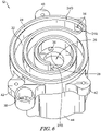
- the drawings show an illustrative embodiment of a scroll pump 10 according to the present disclosure.
- the scroll pump 10 includes: a first (or fixed) scroll member 12; a second (or orbiting) scroll member 14; a camshaft 16 having a first shaft portion 16A and a second shaft portion 16B connected to, spaced from, and parallel to the first shaft portion 16A; a link 18; and a prime mover 20, for example, an electric motor.
- the first scroll member 12 is in orbiting engagement with the second scroll member 14.
- the first shaft portion 16A of the camshaft 16 is rotatably connected to the first scroll member 12.
- the second shaft portion 16B of the camshaft 16 is rotatably connected to the second scroll member 14.
- a first end 18A of the link 18 is pivotably connected to the first scroll member 12, and a second end 18B of the link 18 is pivotably connected to the second scroll member 14.
- the motor 20 is configured to rotate the camshaft 16 with respect to the first scroll member 12 and the second scroll member 14.
- the link 18 substantially precludes rotation of the second scroll member 14 with respect to the first scroll member 12 when the camshaft 16 is rotating, so that rotation of the camshaft 16 causes the second scroll member 14 to orbit with respect to the first scroll member 12.
- the first scroll member 12 includes a first end plate 22 and a first involute 24 extending axially from a first side of the first end plate 22.
- the first end plate 22 defines a first shaft-receiving aperture 26 configured to receive the first shaft portion 16A of the camshaft 16.
- the first end plate 22 also defines a bearing pocket 28 extending into the first end plate 22. In the embodiment shown, the bearing pocket 28 extends toward the first side of the first end plate 22 from a second side of the first end plate 22 opposite the first side of the first end plate 22.
- a first bearing 30 is received within the first bearing pocket 28, for example, in press-fit engagement.
- a land 32 at the bottom of the bearing pocket precludes the bearing 30 from being inserted into and removed from the bearing pocket 28 from the first side of the first end plate 22. The first bearing 30 may abut the land 32.
- the bearing pocket 28 may extend into the first end plate 22 from the first side of the first end plate 22 toward the second side of the first end plate 22.
- the land 32 would preclude the bearing 30 from being inserted into and removed from the bearing pocket 28 from the second side of the first end plate 22.
- first aperture 26 and the bearing pocket 28 may be combined into a single feature and the land 32 may be omitted.
- the first bearing 32 could be inserted into and removed from the bearing pocket 28 from the first side of the first end plate 22 or the second side of the first end plate 22.
- the first bearing 30 is configured to receive the first shaft portion 16A of the camshaft 16 in rotating, bearing engagement.
- the first bearing 30 may be a sealed bearing, and the interfaces among the first end plate 22, the first bearing 30, and the first shaft portion 16A of the camshaft 16 may be substantially sealed interfaces so that the first bearing 32 and the foregoing interfaces are substantially airtight.
- the first involute 24 extends axially from the first side of the first end plate 22 in a direction perpendicular to the first end plate 22.
- a first end 24A of the first involute 24 proximate a periphery of the first involute 24 closes upon an intermediate portion of the first involute 24.
- a second end 24B of the first involute 24 proximate a center of the first involute 24 is free.
- the first end plate 22 and the first involute 24 cooperate to define a space configured to receive a second involute, as will be discussed further below.
- a first tip seal 24S is provided at a free surface of the first involute 24 opposite the first end plate 22.
- the free end of the first involute 24 may define a recess or groove 24G configured to receive and retain the tip seal 24S.
- the first scroll member 12 defines a fluid inlet aperture or port 34 proximate a periphery of the first end 24A of the first involute 24.
- the fluid inlet aperture 34 is configured to admit air or another fluid into the scroll pump 10 for pressurizing thereby.
- the fluid inlet port 34 may extend through one or both of the first end plate 22 and the first involute 24.
- the first scroll member 12 also defines a fluid outlet aperture or port 36 extending through the first end plate 22 proximate the second end 24B of the first involute 24.
- the fluid outlet port 36 is configured to discharge fluid pressurized by the scroll pump 10.
- the first scroll member 12 further defines a first pivot point 38 configured to receive an axle or pin 40 connecting the first end 18A of the link 18 to the first scroll member 12 in pivoting engagement therewith.
- the first pivot point 38 may be embodied as a boss proximate the periphery of the first end plate 22 and/or radially outboard of the first involute 24.
- the first scroll member 12 also may include one or mounting bosses 42 configured to receive fasteners (not shown) for connecting the first scroll member 12 to another structure (not shown).
- a sidewall 44 extends axially from the second side of the first end plate 22.
- the sidewall 44 cooperates with the first end plate 22 to define a housing configured to receive the prime mover 20, in this case an electric motor.
- the sidewall 44 is monolithically formed or integral with the first end plate 22.
- An end cap 46 covers the open end of the sidewall 44.
- a seal 48 for example, an O-ring, may be provided between the housing wall and the end cap so that the interior of the housing is substantially air-tight.
- the second scroll member 14 includes a second end plate 52 and a second involute 54 extending from a first side of the second end plate 52.
- the second end plate 52 defines a second shaft-receiving aperture 56 extending from the first side thereof to a second side thereof opposite the first side.
- the second shaft-receiving aperture 56 is configured to receive a second bearing 58 therein, for example, in press-fit engagement.
- the second end plate 52 also defines one or more vent holes 60 extending therethrough, proximate the center of the second end plate 52, as will be discussed further below.
- An annular sidewall 62 extends axially from the second side of the second end plate 52, thereby defining a cavity 64 extending axially from the second side of the second end plate.
- the cavity 64 is configured to receive a piston 66, as will be discussed further below.
- the cavity 64 may be cylindrical.
- the second involute 54 extends from a first side of the second end plate 52 in a direction perpendicular thereto.
- a second tip seal 54S is provided at a free end of the second involute 54.
- the free end of the second involute 54 may define a recess or groove 54G configured to receive and retain the second tip seal 54S.
- the second scroll member 52 further defines a second pivot point 68 configured to receive a second axle or pin 70 connecting the second end 18B of the link 18 to the second scroll member 14 in pivoting engagement therewith.
- the second pivot point 68 may be embodied as a boss proximate the periphery of the second end plate 52.
- the camshaft 16 includes a first shaft portion 16A and a second shaft portion 16B.
- the first shaft portion 16A defines a first axis of rotation.
- the first axis of rotation is perpendicular to the first end plate 22 and parallel to the first involute 24.
- the second shaft portion 16B defines a second axis of rotation.
- the second axis of rotation is perpendicular to the second end plate 52 and parallel to the second involute 54.
- the second axis of rotation is radially offset from and parallel to the first axis of rotation.
- the first shaft portion 16A is configured for connection to a drive shaft of the prime mover 20 for rotation therewith.
- the camshaft 16 may be integrated and/or monolithically formed with the drive shaft of the prime mover 20.
- the second shaft portion 16B defines a circumferential groove 72 configured to receive a shaft seal 74, for example, an O-ring.
- the shaft seal 74 is engaged between the second shaft portion 16B and an inner race of the second bearing 58.
- a free end of the second shaft portion 16B may define a threaded bore 76 configured to receive a fastener 78, as will be discussed further below.
- the first shaft portion 16A is received within the first bearing 30 in rotating bearing engagement therewith.
- the second shaft portion 16B is received within the second bearing 58 in rotating bearing engagement therewith.
- the first scroll member 12 is axially fixed to the first shaft portion 16A.
- the second scroll member 14 axially floats with respect to the second shaft portion 16B.
- the first scroll member 12 is engaged with the second scroll member 14 so that the first involute 24 is interleaved with the second involute 54.
- the first tip seal 24S of the first scroll member 12 engages with the first side of the second end plate 52 of the second scroll member 14 in sealing engagement therewith.
- the second tip seal 54S of the second scroll member 14 engages with the first side of the first end plate 22 of the first scroll member 12 in sealing engagement therewith. So assembled, the first and second scroll members 12, 14 define a working volume V substantially bounded by the first and second end plates 22, 52 and the first and second involutes 24, 54.
- a first exposed surface area of the second end plate 52 is exposed to fluid pressure within the working volume V.
- the first exposed surface area is defined by the surface area of the first side of the second end plate 52 normal to the second axis of rotation and radially inboard of the first involute 24, minus the surface area of the first side of the second end plate 52 normal to the second axis of rotation occupied by the second involute 54 and covered by the first involute 24/first tip seal 24S.
- the first exposed surface area is the surface area of the first side of the second end plate 52 that projects against the first side of the first end plate 22, minus the surface area of the free end of the second involute 54 engaging the first side of the first end plate.
- a second exposed surface area of the second end plate 52 is exposed to fluid pressure within the cavity 64.
- the second exposed surface area is defined by the surface area of the second side of the second end plate 52 normal to the second axis of rotation within the confines of the cavity 64.
- the second exposed surface area is greater than the first exposed surface area so that when both sides of the second end plate 52 are subjected to the same fluid pressure, the net force on the second end plate 52 parallel to the second axis of rotation tends to bias the second scroll member 14 toward the first scroll member 12, thereby compressing the first and second tip seals 24S, 54S against the respective second and first end plates 52, 22.
- the link 18 is pivotably connected to both the first and second scroll members 12, 14. More specifically, a first portion of the link 18, which may be proximate a first end 18A thereof, is pivotably connected to the first scroll member 12. Similarly, a second portion of the link 18, which may be proximate a second end 18B thereof, is pivotably connected to the second scroll member 14. So connected to the first and second scroll members 12, 14, the link 18 allows the second scroll member 14 to orbit with respect to the first scroll member 12, while substantially precluding rotation of the second scroll member 14 with respect to the first scroll member 12. As shown in the drawings, the camshaft 16 and the link 18 are the only structures constraining the radial position of the second scroll member 14 with respect to the first scroll member 12.
- the piston 66 is received within the cavity 64 defined by the second scroll member 14.
- the piston 66 defines a third bearing-receiving aperture 80 at the center thereof.
- a third bearing 82 is received in the third bearing-receiving aperture 80.
- the third bearing 82 is shown as a flanged bearing received in the third bearing-receiving aperture from a side of the piston 66 facing away from the second scroll member 14.
- the third bearing 82 may be a sealed bearing that substantially precludes fluid flow therethrough.
- the piston 66 also defines a groove 84 about the perimeter thereof.
- the groove 84 is configured to receive a piston seal 86, for example, an O-ring.
- the piston seal 86 substantially precludes fluid flow between the piston 66 and the cavity 64.
- the piston 66 is axially retained to the camshaft 16 by a snap ring 50 received within a snap ring groove 51 defined by the cam shaft 16. More specifically, the piston 66 and the third bearing 82 received therein are disposed between the snap ring 50 and the second scroll member 14. As such, the snap ring 50 limits the axial travel of the third bearing 82 and, therefore, the piston 66, in a direction away from the second scroll member 14. The free end of the second shaft portion 16B of the camshaft 16 may be received within the center of the third bearing 82.
- the third bearing 82 is configured to allow the camshaft 16 to rotate with respect to the second scroll member 14, while the piston 66 remains rotationally fixed with respect to the second scroll member 14.
- a first counterweight 88 may be proximate the base of the second shaft portion 16B of the camshaft 16, where the first shaft portion 16A of the camshaft is connected to the second portion 16B of the camshaft 16. As shown, the first counterweight 88 is disposed within the interior confines of the first involute 24.
- a second counterweight 90 may be provided proximate the free end of the second shaft portion 16B of the camshaft 16. The second counterweight 90 may be connected to the end of the camshaft 16 by a fastener 78, for example, a threaded fastener, extending into the threaded bore 76 defined by the free end of the second shaft portion 16B of the camshaft 16.
- the second counterweight 90 is disposed within the confines of a cavity 67 defined by the piston 66 on the side of the piston 66 opposite the second end plate 52.
- Each of the first and second counterweights 88, 90 is rotationally fixed to the camshaft 16 and may axially fixed thereto, as well.
- a biasing spring 92 is disposed between the second side of the second end plate 52 and the piston 66.
- the biasing spring 92 is an assembly of a plurality of wave washers.
- the biasing spring 92 could be a plurality of distinct wave washers, a single wave washer, an elastomer, or any other suitable biasing member.
- the biasing spring 92 preloads the second scroll member 14 away from the piston 66 and toward the first scroll member 12, thereby engaging the first and second tip seals 24S, 54S with the respective, opposing second and first end plates 52, 22.
- the biasing spring 92 is disposed between the second end plate 52 and the second counterweight 90.
- the biasing spring 92 could be disposed between the piston 66 and the second counterweight 90.
- An end cap 94 covers the cavity 67 and the piston 66 and second counterweight 90 received therein.
- An end cap seal 96 for example, an O-ring, may be provided between the end cap 94 and the second scroll member 14.
- the biasing spring 92 preloads the second scroll member 14 toward the first scroll member 12, thereby engaging the first and second tip seals 24S, 54S with the respective, opposing second and first end plates 52, 22.
- the prime mover 20 rotates the camshaft 16.
- the rotating camshaft 16 causes the second scroll member 14 to orbit with respect to the first scroll member 12.
- the orbiting of the second scroll member 14 with respect to the first scroll member 12 causes the air or another fluid to be drawn into the working volume V through the fluid inlet port 34 and pumped toward the fluid outlet port 36, thereby increasing the pressure of the fluid from the fluid inlet port 34 to the fluid outlet port 36.
- vent holes 60 mitigate this phenomenon by equalizing the fluid pressure on the first and second opposed sides of the second end plate 52 and by applying this equalized pressure to the surface of the piston 66 facing the second end plate 52 (and to the piston seal 86) in a first embodiment or to the end cap 94 (and to the end cap seal 96) in a second embodiment.
- the equalized pressure is applied against the piston 66. Because force equals pressure times area, because the second exposed surface area on the second side of the second end plate 52 is greater than the first exposed surface area on the first side of the second end plate 52, and because the piston 66 is fixed axially with respect to the first scroll member 12, the net axial force acting on the second end plate 52 due to the fluid pressure within the working volume V and the cavity 64 tends to bias the second end plate 52, and therefore the second scroll member 14, toward the first scroll member 12. This net axial force tends to increase as a function of increasing fluid pressure within the working volume V and the cavity 64.
- the second scroll member 14 may be displaced slightly toward the first scroll member 12 in response to the foregoing axial biasing force, thereby compressing the first and second tip seals 24S, 54S against the respective, opposing second and first end plates 52, 22, and thereby promoting operational efficiency of the scroll pump 10.
- the piston 66 may be provided with an optional vent hole 98 similar to vent hole(s) 60 (the optional vent hole 98 is absent in the first embodiment). This may be desirable where the third bearing 82 is not a sealed a bearing. In applications where the third bearing 82 is not a sealed bearing, pressure differential across first and second sides of the third bearing 82 could force grease out of the third bearing 82, potentially leading to premature wear and failure of the third bearing 82. Providing the vent hole 98 in the piston 66 allows for pressure equalization across the piston 66, thereby mitigating against forcing grease out of the third bearing 82 due to pressure differential across the third bearing 82.
- the equalized pressure across the second end plate 52 and the piston 66 bears against the end cap 94 and the end cap seal 96.
- the second scroll member 14 is biased toward the first scroll member 12 in a manner similar to that described above.
- cooperation of the piston 66 with the cavity 64 may provide radial support for the second shaft portion 16B of the camshaft.
Landscapes
- Engineering & Computer Science (AREA)
- Mechanical Engineering (AREA)
- General Engineering & Computer Science (AREA)
- Physics & Mathematics (AREA)
- Fluid Mechanics (AREA)
- Rotary Pumps (AREA)
Priority Applications (1)
| Application Number | Priority Date | Filing Date | Title |
|---|---|---|---|
| EP22216324.8A EP4177439A1 (de) | 2021-04-26 | 2022-04-25 | Spiralpumpe mit mittlerer nockenwelle |
Applications Claiming Priority (1)
| Application Number | Priority Date | Filing Date | Title |
|---|---|---|---|
| US202163179967P | 2021-04-26 | 2021-04-26 |
Related Child Applications (2)
| Application Number | Title | Priority Date | Filing Date |
|---|---|---|---|
| EP22216324.8A Division EP4177439A1 (de) | 2021-04-26 | 2022-04-25 | Spiralpumpe mit mittlerer nockenwelle |
| EP22216324.8A Division-Into EP4177439A1 (de) | 2021-04-26 | 2022-04-25 | Spiralpumpe mit mittlerer nockenwelle |
Publications (2)
| Publication Number | Publication Date |
|---|---|
| EP4083375A2 true EP4083375A2 (de) | 2022-11-02 |
| EP4083375A3 EP4083375A3 (de) | 2023-02-15 |
Family
ID=81386728
Family Applications (2)
| Application Number | Title | Priority Date | Filing Date |
|---|---|---|---|
| EP22216324.8A Withdrawn EP4177439A1 (de) | 2021-04-26 | 2022-04-25 | Spiralpumpe mit mittlerer nockenwelle |
| EP22169728.7A Withdrawn EP4083375A3 (de) | 2021-04-26 | 2022-04-25 | Spiralpumpe mit zentraler nockenwelle |
Family Applications Before (1)
| Application Number | Title | Priority Date | Filing Date |
|---|---|---|---|
| EP22216324.8A Withdrawn EP4177439A1 (de) | 2021-04-26 | 2022-04-25 | Spiralpumpe mit mittlerer nockenwelle |
Country Status (3)
| Country | Link |
|---|---|
| US (1) | US20220341422A1 (de) |
| EP (2) | EP4177439A1 (de) |
| JP (1) | JP2022168847A (de) |
Citations (1)
| Publication number | Priority date | Publication date | Assignee | Title |
|---|---|---|---|---|
| US4609334A (en) * | 1982-12-23 | 1986-09-02 | Copeland Corporation | Scroll-type machine with rotation controlling means and specific wrap shape |
Family Cites Families (16)
| Publication number | Priority date | Publication date | Assignee | Title |
|---|---|---|---|---|
| DE1935621A1 (de) * | 1968-07-22 | 1970-01-29 | Leybold Heraeus Gmbh & Co Kg | Verdraengerpumpe |
| US3884599A (en) * | 1973-06-11 | 1975-05-20 | Little Inc A | Scroll-type positive fluid displacement apparatus |
| JP2562581B2 (ja) * | 1986-08-16 | 1996-12-11 | トキコ株式会社 | 無給油式スクロ−ル圧縮機 |
| US4993928A (en) * | 1989-10-10 | 1991-02-19 | Carrier Corporation | Scroll compressor with dual pocket axial compliance |
| US5085565A (en) * | 1990-09-24 | 1992-02-04 | Carrier Corporation | Axially compliant scroll with rotating pressure chambers |
| US5129798A (en) * | 1991-02-12 | 1992-07-14 | American Standard Inc. | Co-rotational scroll apparatus with improved scroll member biasing |
| US5258046A (en) * | 1991-02-13 | 1993-11-02 | Iwata Air Compressor Mfg. Co., Ltd. | Scroll-type fluid machinery with seals for the discharge port and wraps |
| AU4645196A (en) * | 1994-12-23 | 1996-07-19 | Bristol Compressors, Inc. | Scroll compressor having bearing structure in the orbiting scroll to eliminate tipping forces |
| US5593295A (en) * | 1995-04-19 | 1997-01-14 | Bristol Compressors, Inc. | Scroll compressor construction having an axial compliance mechanism |
| GB9912212D0 (en) * | 1999-05-26 | 1999-07-28 | Boc Group Plc | Scroll-type apparatus |
| JP2000352386A (ja) * | 1999-06-08 | 2000-12-19 | Mitsubishi Heavy Ind Ltd | スクロール圧縮機 |
| US7467933B2 (en) * | 2006-01-26 | 2008-12-23 | Scroll Laboratories, Inc. | Scroll-type fluid displacement apparatus with fully compliant floating scrolls |
| US7371059B2 (en) * | 2006-09-15 | 2008-05-13 | Emerson Climate Technologies, Inc. | Scroll compressor with discharge valve |
| US7611344B2 (en) * | 2007-10-15 | 2009-11-03 | Scroll Laboratories, Inc. | Sealing tabs on orbiting scroll |
| KR102043154B1 (ko) * | 2018-05-04 | 2019-11-11 | 엘지전자 주식회사 | 전동식 압축기 |
| KR102086349B1 (ko) * | 2018-08-31 | 2020-03-09 | 엘지전자 주식회사 | 전동식 압축기 |
-
2022
- 2022-04-25 US US17/728,546 patent/US20220341422A1/en not_active Abandoned
- 2022-04-25 JP JP2022071237A patent/JP2022168847A/ja active Pending
- 2022-04-25 EP EP22216324.8A patent/EP4177439A1/de not_active Withdrawn
- 2022-04-25 EP EP22169728.7A patent/EP4083375A3/de not_active Withdrawn
Patent Citations (1)
| Publication number | Priority date | Publication date | Assignee | Title |
|---|---|---|---|---|
| US4609334A (en) * | 1982-12-23 | 1986-09-02 | Copeland Corporation | Scroll-type machine with rotation controlling means and specific wrap shape |
Also Published As
| Publication number | Publication date |
|---|---|
| EP4177439A1 (de) | 2023-05-10 |
| EP4083375A3 (de) | 2023-02-15 |
| US20220341422A1 (en) | 2022-10-27 |
| JP2022168847A (ja) | 2022-11-08 |
Similar Documents
| Publication | Publication Date | Title |
|---|---|---|
| KR100554910B1 (ko) | 방출밸브를 갖춘 스크롤 머신 | |
| US7988434B2 (en) | Compressor having capacity modulation system | |
| US8529232B2 (en) | Compressor having capacity modulation system | |
| US6196814B1 (en) | Positive displacement pump rotatable in opposite directions | |
| EP2417356B1 (de) | Verdichter mit kapazitätsmodulationsanordnung | |
| KR101287428B1 (ko) | 유체 분사 시스템을 구비한 컴프레서 | |
| US8052406B2 (en) | Scroll machine having improved discharge valve assembly | |
| US20070110604A1 (en) | Scroll machine | |
| KR100916554B1 (ko) | 올덤 커플링을 위한 클리어런스를 가진 스크롤 압축기 | |
| EP1818541B1 (de) | Horizontal montierter Spiralverdichter | |
| US4548555A (en) | Scroll type fluid displacement apparatus with nonuniform scroll height | |
| MXPA02008501A (es) | Valvula de descarga de compresor. | |
| CA2174200C (en) | Scroll compressor having a suction check valve | |
| JP5550419B2 (ja) | 圧縮機 | |
| EP3032103B1 (de) | Spiralverdichter | |
| JPH05149269A (ja) | スクロール型流体機械 | |
| CN210033825U (zh) | 排放阀组件和涡旋压缩机 | |
| US4431380A (en) | Scroll compressor with controlled suction unloading using coupling means | |
| EP4083375A2 (de) | Spiralpumpe mit zentraler nockenwelle | |
| CN112081743A (zh) | 排放阀组件和涡旋压缩机 | |
| CN110017276B (zh) | 涡旋压缩机 | |
| US6158994A (en) | Grooved rotor for an internal gear pump | |
| US5848883A (en) | Scroll compressor having a back pressure partitioning member | |
| EP4269800A1 (de) | Spiralpumpe mit axiallaststeuersystem | |
| JPH0849681A (ja) | スクロール型圧縮機 |
Legal Events
| Date | Code | Title | Description |
|---|---|---|---|
| PUAI | Public reference made under article 153(3) epc to a published international application that has entered the european phase |
Free format text: ORIGINAL CODE: 0009012 |
|
| STAA | Information on the status of an ep patent application or granted ep patent |
Free format text: STATUS: THE APPLICATION HAS BEEN PUBLISHED |
|
| AK | Designated contracting states |
Kind code of ref document: A2 Designated state(s): AL AT BE BG CH CY CZ DE DK EE ES FI FR GB GR HR HU IE IS IT LI LT LU LV MC MK MT NL NO PL PT RO RS SE SI SK SM TR |
|
| RIC1 | Information provided on ipc code assigned before grant |
Ipc: F01C 19/08 20060101ALI20221007BHEP Ipc: F04C 18/067 20060101ALI20221007BHEP Ipc: F04C 18/02 20060101ALI20221007BHEP Ipc: F01C 21/10 20060101ALI20221007BHEP Ipc: F01C 17/06 20060101AFI20221007BHEP |
|
| PUAL | Search report despatched |
Free format text: ORIGINAL CODE: 0009013 |
|
| AK | Designated contracting states |
Kind code of ref document: A3 Designated state(s): AL AT BE BG CH CY CZ DE DK EE ES FI FR GB GR HR HU IE IS IT LI LT LU LV MC MK MT NL NO PL PT RO RS SE SI SK SM TR |
|
| RIC1 | Information provided on ipc code assigned before grant |
Ipc: F01C 19/08 19680901ALI20230109BHEP Ipc: F04C 18/067 19800101ALI20230109BHEP Ipc: F04C 18/02 19800101ALI20230109BHEP Ipc: F01C 21/10 19680901ALI20230109BHEP Ipc: F01C 17/06 19680901AFI20230109BHEP |
|
| P01 | Opt-out of the competence of the unified patent court (upc) registered |
Effective date: 20230529 |
|
| STAA | Information on the status of an ep patent application or granted ep patent |
Free format text: STATUS: REQUEST FOR EXAMINATION WAS MADE |
|
| 17P | Request for examination filed |
Effective date: 20230814 |
|
| RBV | Designated contracting states (corrected) |
Designated state(s): AL AT BE BG CH CY CZ DE DK EE ES FI FR GB GR HR HU IE IS IT LI LT LU LV MC MK MT NL NO PL PT RO RS SE SI SK SM TR |
|
| STAA | Information on the status of an ep patent application or granted ep patent |
Free format text: STATUS: EXAMINATION IS IN PROGRESS |
|
| 17Q | First examination report despatched |
Effective date: 20241028 |
|
| STAA | Information on the status of an ep patent application or granted ep patent |
Free format text: STATUS: THE APPLICATION IS DEEMED TO BE WITHDRAWN |
|
| 18D | Application deemed to be withdrawn |
Effective date: 20250429 |