EP4083845B1 - Verfahren zur diagnose von weichenfehlern, gerät zur diagnose von weichenfehlern - Google Patents
Verfahren zur diagnose von weichenfehlern, gerät zur diagnose von weichenfehlern Download PDFInfo
- Publication number
- EP4083845B1 EP4083845B1 EP21762322.2A EP21762322A EP4083845B1 EP 4083845 B1 EP4083845 B1 EP 4083845B1 EP 21762322 A EP21762322 A EP 21762322A EP 4083845 B1 EP4083845 B1 EP 4083845B1
- Authority
- EP
- European Patent Office
- Prior art keywords
- turnout
- target
- discrete sequence
- curve
- action curve
- Prior art date
- Legal status (The legal status is an assumption and is not a legal conclusion. Google has not performed a legal analysis and makes no representation as to the accuracy of the status listed.)
- Active
Links
Images


Classifications
-
- G—PHYSICS
- G06—COMPUTING OR CALCULATING; COUNTING
- G06F—ELECTRIC DIGITAL DATA PROCESSING
- G06F30/00—Computer-aided design [CAD]
- G06F30/20—Design optimisation, verification or simulation
-
- B—PERFORMING OPERATIONS; TRANSPORTING
- B61—RAILWAYS
- B61L—GUIDING RAILWAY TRAFFIC; ENSURING THE SAFETY OF RAILWAY TRAFFIC
- B61L27/00—Central railway traffic control systems; Trackside control; Communication systems specially adapted therefor
- B61L27/50—Trackside diagnosis or maintenance, e.g. software upgrades
- B61L27/53—Trackside diagnosis or maintenance, e.g. software upgrades for trackside elements or systems, e.g. trackside supervision of trackside control system conditions
-
- B—PERFORMING OPERATIONS; TRANSPORTING
- B61—RAILWAYS
- B61L—GUIDING RAILWAY TRAFFIC; ENSURING THE SAFETY OF RAILWAY TRAFFIC
- B61L5/00—Local operating mechanisms for points or track-mounted scotch-blocks; Visible or audible signals; Local operating mechanisms for visible or audible signals
- B61L5/06—Electric devices for operating points or scotch-blocks, e.g. using electromotive driving means
-
- G—PHYSICS
- G06—COMPUTING OR CALCULATING; COUNTING
- G06Q—INFORMATION AND COMMUNICATION TECHNOLOGY [ICT] SPECIALLY ADAPTED FOR ADMINISTRATIVE, COMMERCIAL, FINANCIAL, MANAGERIAL OR SUPERVISORY PURPOSES; SYSTEMS OR METHODS SPECIALLY ADAPTED FOR ADMINISTRATIVE, COMMERCIAL, FINANCIAL, MANAGERIAL OR SUPERVISORY PURPOSES, NOT OTHERWISE PROVIDED FOR
- G06Q10/00—Administration; Management
- G06Q10/20—Administration of product repair or maintenance
-
- Y—GENERAL TAGGING OF NEW TECHNOLOGICAL DEVELOPMENTS; GENERAL TAGGING OF CROSS-SECTIONAL TECHNOLOGIES SPANNING OVER SEVERAL SECTIONS OF THE IPC; TECHNICAL SUBJECTS COVERED BY FORMER USPC CROSS-REFERENCE ART COLLECTIONS [XRACs] AND DIGESTS
- Y04—INFORMATION OR COMMUNICATION TECHNOLOGIES HAVING AN IMPACT ON OTHER TECHNOLOGY AREAS
- Y04S—SYSTEMS INTEGRATING TECHNOLOGIES RELATED TO POWER NETWORK OPERATION, COMMUNICATION OR INFORMATION TECHNOLOGIES FOR IMPROVING THE ELECTRICAL POWER GENERATION, TRANSMISSION, DISTRIBUTION, MANAGEMENT OR USAGE, i.e. SMART GRIDS
- Y04S10/00—Systems supporting electrical power generation, transmission or distribution
- Y04S10/50—Systems or methods supporting the power network operation or management, involving a certain degree of interaction with the load-side end user applications
- Y04S10/52—Outage or fault management, e.g. fault detection or location
Definitions
- Embodiments of the present disclosure relate to the technical field of railway transportation, and in particular, to a turnout fault diagnosing method, a turnout fault diagnosing apparatus, an electronic device and a computer-readable storage medium.
- a turnout switching device is one of the three outdoor parts of a railway signal device, and if the turnout switching device has a fault, traffic will be severely affected. Since a turnout rotates very frequently in railway operation and a fault rate is relatively high, inspection and maintenance of the turnout is very important.
- a related technology is to establish a fault standard curve library of the turnout, and to compare turnout action curves with the fault standard curve library in real time sequentially to give out the fault content of the turnout.
- establishment of the fault standard curve library needs to be supported by massive actual fault curve data, the standard curve library is difficult to establish, and judgment of a turnout fault depends on the number of standard fault curves of fault curves in the curve library, which has very low applicability; and in a case of different shapes of turnout action curves in engineering application, accuracy of fault diagnosis will be seriously reduced.
- Embodiments of the present disclosure provides a turnout fault diagnosing method, a turnout fault diagnosing apparatus, an electronic device and a computer-readable storage medium so as to accurately locate start and end positions of each turnout action, to solve the problem that the accuracy of turnout fault diagnosis is reduced due to the different shapes of the turnout action curves.
- start and end points of each turnout action phase in the turnout action curve can be determined according to the value of each discrete sequence item in the turnout action curve, so as to implement accurate location of an action curve that is experienced by each turnout action phase, and on such basis, directional diagnosis can be performed on action curve segments that are experienced by each turnout action phase respectively, to avoid that targeted fault diagnosis cannot be performed due to the fact that time lengths of a same turnout action phase in different turnout action curves are inconsistent and there are many types of turnout action phases, thereby solving the problem that the accuracy of turnout fault diagnosis is reduced due to different shapes of the turnout action curves, and the technical effect that the position of a turnout fault is located more accurately, which helps a device maintainer to quickly handle the fault, to reduce the influence time on the railway operation can be achieved.
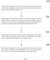
- FIG. 1 is a flowchart of a turnout fault diagnosing method provided by embodiment one of the present invention.
- the method can be applied to a case where fault diagnosis is performed when a railway track turnout is switched, the method can be executed by a turnout fault diagnosing apparatus, and the apparatus can be implemented by software and/or hardware, and can be integrated into an electronic device having a network communication function.
- the turnout fault diagnosing method in this embodiment includes steps of: S 110: a target turnout action curve of a target turnout is acquired; the turnout action curve includes a series of discrete sequence items generated turnout actions at different trigger times.
- a turnout fault diagnosis system acquires the target turnout action curve of the target turnout, in the process of using a turnout switching device to execute turnout rotation, corresponding discrete sequence items will be generated at different rotation trigger times, and these discrete sequence items are connected to form a turnout action curve when the turnout rotation is executed.
- One turnout action curve can include four turnout action phases of turnout unlocking, turnout rotation, turnout locking, and switch termination.
- the turnout action curve can be a turnout action power curve or a turnout action current curve that is generated by executing the turnout actions, the type of a discrete sequence item can be power or current, and the value of the discrete sequence item can be a power value or a current value.
- the turnout action curve includes a series of discrete sequence items generated by the turnout actions at different trigger times.
- S 120 the target turnout action curve is segmented, according to the value of each discrete sequence item in the target turnout action curve.
- the turnout fault diagnosis system segments the target turnout action curve according to the value of each discrete sequence item in the target turnout action curve. All discrete sequence items can be divided into turnout action phases to which they belong according to the value of each discrete sequence item, and thus, the turnout action curve can be segmented into four turnout action phases of turnout unlocking, turnout rotation, turnout locking, and switch termination, and each turnout action phase will have multiple turnout action curve segments that consist of the discrete sequence items.
- segmenting the target turnout action curve according to the value of each discrete sequence item in the target turnout action curve may include operations of: Taking the discrete sequence item with the maximum value in the discrete sequence items in the turnout action curve as a start point of the turnout unlocking phase in the target turnout action curve.
- turnout fault diagnosis takes the discrete sequence item with the maximum value in the discrete sequence items of the turnout action curve as the start point of the turnout unlocking phase in the target turnout action curve, that is, a first sequence item of the discrete sequence items in the turnout unlocking phase of the four turnout action phases in the turnout action curve.
- a maximum value sequence item is Bx
- the start point of the turnout unlocking phase in the target turnout action curve is (Ax, Bx).
- segmenting the target turnout action curve according to the value of each discrete sequence item in the target turnout action curve may further include operations of: Taking a last discrete sequence item whose value is non-zero in the target turnout action curve as a start point of the rotation termination phase in the target turnout action curve, and taking the last discrete sequence item in the target turnout action curve as an end point of the rotation termination phase in the target turnout action curve, when it is determined that there is a discrete sequence item that its value is zero in the target turnout action curve.
- the last discrete sequence item whose value is non-zero in the target turnout action curve is taken as the start point of the rotation termination phase in the target turnout action curve
- the last discrete sequence item in the target turnout action curve is taken as an end point of the rotation termination phase in the target turnout action curve, when it is determined that there is a discrete sequence item whose value is zero in the target turnout action curve.
- the end point of the rotation termination phase in the target turnout action curve is (An, Bn)
- sorting is performed in time sequence
- the last discrete sequence item that its value is non-zero is (Ah, Bh).
- S130 fault diagnosis is performed on curve segments divided into each turnout action phase, according to the segmentation result of the target turnout action curve, so as to implement the fault diagnosis of the target turnout.
- turnout fault diagnosis system performs fault diagnosis for curve segments of each phase, according to the segmentation result of the target turnout action curve, so as to implement the fault diagnosis of the target turnout.
- performing the fault diagnosis on the curve segments divided into each turnout action phase, according to the segmentation result of the target turnout action curve, so as to implement the fault diagnosis of the target turnout includes the steps of:
- this embodiment acquires the target turnout action curve of the target turnout, then segments the target turnout action curve according to the value of each discrete sequence item in the target turnout action curve, and finally performs fault diagnosis on the curve segments divided into each turnout action phase, according to the segmentation result of the turnout action curve, so as to implement the fault diagnosis of the target turnout, such that a turnout fault is located more accurately, which helps the device maintainer to quickly handle the fault, to reduce the influence time on the railway operation, which has very high practicability.
- FIG. 2 is a flowchart of another turnout fault diagnosing method provided by embodiment two of the present application.
- the embodiment of the present invention further optimizes the foregoing embodiment on the basis of the above embodiment, and the embodiment of the present invention may be combined with each optional solution in the above one or more embodiments.
- the turnout fault diagnosing method provided by the embodiment of the present invention may include steps of:
- S210 a target turnout action curve of the target turnout is acquired; the turnout action curve including a series of discrete sequence items generated by the turnout actions at different trigger times.
- target discrete sequence items are determined from all discrete sequence items according to the value of each discrete sequence item in the target turnout action curve; the aggregation density of the target discrete sequence items is greater than a preset density threshold value.
- the turnout fault diagnosis system determines target high-density discrete sequence items from all discrete sequence items according to the value of each discrete sequence item in the target turnout action curve, and the aggregation density of the target high-density discrete sequence items is greater than the preset density threshold value.
- determining the target discrete sequence items that its aggregation density is greater than the preset density threshold value from all discrete sequence items, according to the value of each discrete sequence item in the target turnout action curve may include steps A1-A3:
- determining the target discrete sequence items that its aggregation density is greater than the preset density threshold value from all the discrete sequence items can make each discrete sequence item regarded as a value range center, and any discrete sequence item can be expressed as Bi, then it can be that each discrete sequence item Bi is taken as the value range center, and Bx (the value of the maximum value sequence item)/50 is taken as a value range radius, the discrete sequence items contained in a value range can form a point set Bi, that is, the value difference between the value of the discrete sequence item Bi and the value of each discrete sequence item is calculated, and the discrete sequence items whose value difference is less than the value range radius of Bi are made to compose a point set (cluster) of Bi.
- the ratio of the number of the discrete sequence items falling in the point set Bi to the total number of discrete value points is calculated to obtain the density value Pi of the discrete sequence item B1, and a point that its density value is greater than a preset density threshold value is regarded as a high-density point, that is, the target discrete sequence items, where the preset density threshold value can be 0.5 or 0.6.
- the target discrete sequence item is found out by judging the number of all discrete sequence items falling in the value range.
- start point and the end point corresponding to the turnout rotation phase in the target turnout action curve are determined, according to the trigger times corresponding to the target discrete sequence items.
- determining the start point and the end point corresponding to the turnout rotation phase in the target turnout action curve, according to the trigger times corresponding to the target discrete sequence items may includes steps B1-B2:
- the target discrete sequence items can be sorted in time domain according to the time discrete sequence, and forward-most and rearward-most target discrete sequence items of the target discrete sequence in time domain are taken as the start and end points of the turnout switch phase, respectively.
- the target discrete sequence items are sorted in time domain according to the time discrete sequence, a forward-most point is (Aj, Bj), and a rearward-most point is (Ak, Bk).
- the turnout unlocking phase is a curve from (Ax, Bx) to (Aj, Bj)
- the turnout switch phase is a curve from (Aj, Bj) to (Ak, Bk)
- the turnout locking phase is a curve from (Ak, Bk) to (Ah, Bh)
- the switch termination phase is a curve from (Ah, Bh) to (An, Bn).
- S240 fault diagnosis is performed on the curve segment divided into each turnout action phase, according to the segmentation result of the target turnout action curve, so as to implement the fault diagnosis of the target turnout.
- this embodiment acquires the target turnout action curve of the target turnout, and then determines the target discrete sequence items from all discrete sequence items according to the value of each discrete sequence item in the target turnout action curve; the aggregation density of the target discrete sequence items is greater than the preset density threshold value, and then the start point and the end point corresponding to the turnout rotation phase of the target turnout action curve are determined according to the trigger times corresponding to the target discrete sequence items, and finally, fault diagnosis is performed on the curve segments divided into each turnout action phase, according to the segmentation result of the turnout action curve, thus achieving that a curve of the turnout switch phase is determined by calculating the distribution density of discrete sequence items, so as to implement the fault diagnosis of each phase of the target turnout, such that the position of the turnout fault is located more accurately, which helps the device maintainer to quickly handle the fault, which has higher applicability, and solves the problem that the accuracy of fault diagnosis is reduced due to the different shapes of the turnout curves in
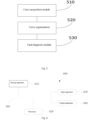
- FIG. 5 is a structural schematic diagram of a turnout fault diagnosing apparatus provided by embodiment three of the present disclose.
- the apparatus can be applied to a case that fault diagnosis is performed when the railway track turnout is switched, and the apparatus can be implementd by software and/or hardware, and is integrated in an electronic device.
- the apparatus is used to implement the turnout fault diagnosing method provided by the foregoing embodiment.
- the turnout fault diagnosing apparatus provided in this embodiment includes:
- the type of the discrete sequence item being power or current.
- the curve segmentation module 520 is configured to: Take the discrete sequence item with the maximum value in the discrete sequence items in the turnout action curve as the start point of the turnout unlocking phase in the target turnout action curve.
- the curve segmentation module 520 is further configured to: Take the last discrete sequence item whose value is non-zero in the target turnout action curve as the start point of the rotation termination phase in the target turnout action curve, and taking the last discrete sequence item in the target turnout action curve as the end point of the rotation termination phase in the target turnout action curve, when it is determined that there is a discrete sequence item that its value is zero in the target turnout action curve.
- the curve segmentation module 520 is further configured to:
- the curve segmentation module 520 is further configured to: Determine the target discrete sequence items that its aggregation density is greater than a preset density threshold value from each discrete sequence item, according to the value of each discrete sequence item in the target turnout action curve, includes:
- the curve segmentation module 520 is further configured to: Determine the start point and the end point corresponding to the turnout rotation phase of the target turnout action curve, according to the trigger times corresponding to the target discrete sequence items, includes:
- the fault diagnosis module 530 is configured to:
- the turnout fault diagnosing apparatus provided by the embodiment of the present invention can execute the turnout fault diagnosing method provided by any embodiment of the present invention, and has corresponding functions and beneficial effects of executing the turnout fault diagnosing method.
- the detailed process refer to the related operations of the turnout fault diagnosing method in the foregoing embodiment.
- FIG. 6 is a structural schematic diagram of an electronic device provided by embodiment four of the present application.
- the embodiment of the present application provides an electronic device, in which the turnout fault diagnosing apparatus provided by the embodiment of the present application can be integrated.
- this embodiment provides an electronic device 600, including: one or more processors 620; a storing apparatus 610, configured to store one or more programs, when the one or more programs are executed by the one or more processors 620, the one or more processors 620 implementing the turnout fault diagnosing method provided in the embodiment of the present application, the method including:
- processor 620 further implements the technical solution of the turnout fault diagnosing method provided by any embodiment of the present application.
- the electronic device 600 shown in FIG. 6 is only an example, and should not make any limitation to the functions and scope of use of the embodiments of the present application.
- the electronic device 600 includes a processor 620, a storing apparatus 610, an input apparatus 630, and an output apparatus 640; the number of processors 620 in the electronic device may be one or more, and in FIG. 6 , one processor 620 is taken as an example; the processor 620, the storing apparatus 610, the input apparatus 630, and the output apparatus 640 in the electronic device may be connected by a bus or other means, and In FIG. 6 , the connection with the bus 650 is taken as an example.
- the storing apparatus 610 can be configured to store software programs, computer-executable programs, and module units, such as program instructions corresponding to the turnout fault diagnosing method in the embodiment of the present application.
- the storing apparatus 610 may mainly include a storage program region and a storage data region, wherein the storage program region may store an operating system and an application program that is required by at least one function; the storage data region may store data that is created according to the use of a terminal, and the like.
- the storing apparatus 610 may include a high-speed random access memory, and may further include a non-volatile memory, such as at least one magnetic disk storage device, a flash memory device, or other non-volatile solid-state storage devices.
- the storing apparatus 610 may further include memories remotely provided with respect to the processor 620, and these remote memories may be connected via a network. Examples of the above network include, but are not limited to, the Internet, Intranet, local area networks, mobile communication networks, and combinations thereof.
- the input apparatus 630 may be used to receive inputted numbers, character information, or voice information, and generate key signal input related to user settings and function control of the electronic device.
- the output apparatus 640 may include electronic devices, such as a display screen, a loudspeaker, etc.
- the electronic equipment provided by the embodiment of the present application can achieve the technical effect that the position of the turnout fault is located more accurately, which helps the device maintainer to quickly handle the fault, to shorten the influence time on the railway operation.
- Embodiment five of the present invention provides a computer-readable medium having a computer program stored thereon, and when being executed by a processor, the program is used to perform a turnout fault diagnosing method, the method including:
- the program when being executed by the processor, the program can further be used to execute the switch fault diagnosing method provided by any embodiment of the present invention.
- the computer storage medium of the embodiment of the present invention may adopt any combination of one or more computer-readable mediums.
- the computer-readable medium may be a computer-readable signal medium or a computer-readable storage medium.
- the computer-readable storage medium may be, for example, but not limited to, an electrical, magnetic, optical, electromagnetic, infrared, or semi-conductive system, apparatus, or device, or any combination of the above.
- Computer-readable storage mediums include: electrical connection with one or more wires, a portable computer disk, a hard disk, Random Access Memory (RAM), Read Only Memory (ROM), Erasable Programmable Read Only Memory (EPROM), a flash memory, an optical fiber, a portable CD-ROM, an optical storage device, a magnetic storage device, or any suitable combination of the foregoing.
- the computer-readable storage medium may be any tangible medium that contains or stores a program, and the program may be used by or in combination with an instruction execution system, apparatus, or device.
- the computer-readable signal medium may include a data signal propagated in baseband or as a part of a carrier, and a computer-readable program code is carried therein. This propagated data signal can take many forms, including but not limited to: electromagnetic signals, optical signals, or any suitable combination thereof.
- the computer-readable signal medium may also be any computer-readable medium other than a computer-readable storage medium, and the computer-readable medium may send, propagate, or transmit the program for use by or in combination with the instruction execution system, apparatus, or device.
- a program code contained on the computer readable medium can be transmitted by any suitable medium, including but not limited to: wireless, wire, optical cable, Radio Frequency (RF), etc., or any suitable combination thereof.
- suitable medium including but not limited to: wireless, wire, optical cable, Radio Frequency (RF), etc., or any suitable combination thereof.
- the computer program code used to perform the operations of the present invention can be written in one or more programming languages or a combination thereof, the programming languages include object-oriented programming languages, such as Java, Smalltalk, C++, and further including conventional procedural programming languages, such as "C" language or similar programming language.
- the program code can be executed completely on the user's computer, partly on the user's computer, as a stand-alone software package, partly on the user's computer and partly on a remote computer, or completely on a remote computer or a server.
- the remote computer may be connected to the user's computer through any type of network, including Local Area Network (LAN) or Wide Area Network (WAN), or connected to an external computer (for example, through the Internet connection from an Internet Service Provider).
- LAN Local Area Network
- WAN Wide Area Network
- Internet Service Provider for example, AT&T, MCI, Sprint, EarthLink, MSN, GTE, etc.
Landscapes
- Engineering & Computer Science (AREA)
- Physics & Mathematics (AREA)
- Business, Economics & Management (AREA)
- Theoretical Computer Science (AREA)
- Mechanical Engineering (AREA)
- Human Resources & Organizations (AREA)
- General Physics & Mathematics (AREA)
- General Business, Economics & Management (AREA)
- Biomedical Technology (AREA)
- Strategic Management (AREA)
- Tourism & Hospitality (AREA)
- Operations Research (AREA)
- Marketing (AREA)
- Entrepreneurship & Innovation (AREA)
- Economics (AREA)
- Health & Medical Sciences (AREA)
- Quality & Reliability (AREA)
- General Health & Medical Sciences (AREA)
- Computer Hardware Design (AREA)
- Evolutionary Computation (AREA)
- Geometry (AREA)
- General Engineering & Computer Science (AREA)
- Train Traffic Observation, Control, And Security (AREA)
- Electric Propulsion And Braking For Vehicles (AREA)
Claims (8)
- Verfahren zum Diagnostizieren eines Weichenfehlers, Folgendes umfassend:(S110) Erfassen einer Ziel-Weichenaktionskurve einer Ziel-Weiche; wobei die Weichenaktionskurve eine Reihe von diskreten Sequenzelementen umfasst, die durch Weichenaktionen zu verschiedenen Auslösezeiten erzeugt werden;(S120) Segmentieren der Ziel-Weichenaktionskurve in Kurvensegmente, gemäß den Werten der diskreten Sequenzelemente in der Ziel-Weichenaktionskurve; und(S130) gemäß dem segmentierten Ergebnis der Ziel-Weichenaktionskurve, Durchführen einer Fehlerdiagnose an dem Kurvensegment in jeder Weichenaktionsphase, sodass die Fehlerdiagnose für die Ziel-Weiche implementiert wird, beinhaltendin einer Weichenentriegelungsphase und einer Weichenumschaltphase, wenn Werte der diskreten Sequenzelemente in Kurvensegmenten in der Weichenentriegelungsphase und der Weichenumschaltphase in der Ziel-Weichenaktionskurve kontinuierlich größer als ein Weichenentriegelungsschwellenwert für eine voreingestellte Zeitperiode sind, Bestimmen, dass die Ziel-Weiche einen Weichenentriegelungsfehler aufweist;in einer Weichenumschaltphase, wenn Werte der diskreten Sequenzelemente in Kurvensegmenten in der Weichenumschaltphase in der Ziel-Weichenaktionskurve kontinuierlich weniger als ein Weichenleerlaufschwellenwert für eine voreingestellte Zeitperiode sind, Bestimmen, dass die Ziel-Weiche einen Weichenleerlauffehler aufweist;in einer Weichenumschaltphase, wenn die Ziel-Weichenaktionskurve größer als ein Weichenstauschwellenwert ist, Bestimmen, dass die Ziel-Weiche einen Weichenstaufehler aufweist;in einer Weichenverriegelungsphase, wenn Werte der diskreten Sequenzelemente in Kurvensegmenten in der Weichenverriegelungsphase der Ziel-Weichenaktionskurve alle größer als Null sind, Bestimmen, dass die Ziel-Weiche einen Weichenentriegelungsfehler aufweist.
- Verfahren nach Anspruch 1, wobei ein Typ der diskreten Sequenzelemente Energie oder Strom ist.
- Verfahren nach Anspruch 1, wobei das Segmentieren der Ziel-Weichenaktionskurve gemäß den Werten der diskreten Sequenzelemente in der Ziel-Weichenaktionskurve Folgendes umfasst:
Nehmen eines diskreten Sequenzelements mit einem Maximalwert in den diskreten Sequenzelementen in der Weichenaktionskurve als Startpunkt einer Weichenentriegelungsphase in der Ziel-Weichenaktionskurve. - Verfahren nach Anspruch 1, wobei das Segmentieren der Ziel-Weichenaktionskurve gemäß den Werten der diskreten Sequenzelemente in der Ziel-Weichenaktionskurve Folgendes umfasst:(S220) Bestimmen von diskreten Ziel-Sequenzelementen aus allen diskreten Sequenzelementen, gemäß den Werten der diskreten Sequenzelemente in der Ziel-Weichenaktionskurve, beinhaltend für jedes diskrete Sequenzelement in der Ziel-Weichenaktionskurve, Bestimmen einiger anderer diskreter Sequenzelemente, zwischen denen und dem jeweiligen diskreten Sequenzelement eine Wertedifferenz innerhalb eines voreingestellten Differenzbereichs liegt, von allen diskreten Sequenzelementen in der Ziel-Weichenaktionskurve;Nehmen des Verhältnisses der Anzahl der einigen anderen diskreten Sequenzelemente zu der Gesamtanzahl der diskreten Sequenzelemente in der Ziel-Weichenaktionskurve als die Aggregationsdichte der jeweiligen diskreten Sequenzelemente; undNehmen diskreter Sequenzelemente, deren Aggregationsdichte in den diskreten Sequenzelementen der Ziel-Weichenaktionskurve größer als der voreingestellte Dichteschwellenwert ist, als die diskreten Ziel-Sequenzelemente; und(S230) Bestimmen eines Startpunktes und eines Endpunktes, die einer Weichenrotationsphase in der Ziel-Weichenaktionskurve entsprechen, gemäß den Auslösezeiten, die den diskreten Ziel-Sequenzelementen entsprechen.
- Verfahren nach Anspruch 4, wobei das Bestimmen des Startpunktes und des Endpunktes, die der Weichenrotationsphase der Ziel-Weichenaktionskurve entsprechen, gemäß den Auslösezeiten, die den diskreten Ziel-Sequenzelementen entsprechen, Folgendes umfasst:Sortieren benachbarter diskreter Ziel-Sequenzelemente, gemäß der Sequenz der Auslösezeiten, die den diskreten Ziel-Sequenzelementen entspricht;Nehmen der ersten diskreten Ziel-Sequenz und des letzten diskreten Ziel-Sequenzelements aus einem Sortierergebnis als den Startpunkt beziehungsweise den Endpunkt der Weichenrotationsphase in der Ziel-Weichenaktionskurve.
- Gerät zum Diagnostizieren eines Weichenfehlers, das so konfiguriert ist, dass es das Verfahren der Ansprüche 1 bis 5 durchführt, Folgendes umfassend:ein Kurvenerfassungsmodul (510), das so konfiguriert ist, dass es die Ziel-Weichenaktionskurve der Ziel-Weiche erfasst; wobei die Weichenaktionskurve eine Reihe von diskreten Sequenzelementen umfasst, die durch die Weichenaktionen zu verschiedenen Auslösezeiten erzeugt werden;ein Kurvensegmentierungsmodul (520), das so konfiguriert ist, dass es die Ziel-Weichenaktionskurve gemäß dem Wert jedes diskreten Sequenzelements in der Ziel-Weichenaktionskurve segmentiert; undein Fehlerdiagnosemodul (530), das so konfiguriert ist, dass es die Fehlerdiagnose an dem Kurvensegment in jeder Weichenaktionsphase gemäß dem segmentierten Ergebnis der Ziel-Weichenaktionskurve durchführt, sodass die Fehlerdiagnose für die Ziel-Weiche implementiert wird.
- Elektronische Vorrichtung (600), Folgendes umfassend:einen oder mehrere Prozessoren (620);ein Speichergerät (610), das so konfiguriert ist, dass es ein oder mehrere Programme speichert, die Anweisungen aufweisen;wobei, wenn das eine oder die mehreren Programme durch den einen oder die mehreren Prozessoren ausgeführt werden, die Anweisungen den einen oder die mehreren Prozessoren veranlassen, das Verfahren zum Diagnostizieren eines Weichenfehlers gemäß einem der Ansprüche 1-5 durchzuführen.
- Computerlesbares Speichermedium, das ein darauf gespeichertes Computerprogramm aufweist, wobei das Programm Anweisungen umfasst, die, wenn das Programm durch einen Prozessor ausgeführt wird, den Prozessor veranlassen, das Verfahren zum Diagnostizieren eines Weichenfehlers nach einem der Ansprüche 1-5 durchzuführen.
Priority Applications (1)
| Application Number | Priority Date | Filing Date | Title |
|---|---|---|---|
| RS20241240A RS66164B1 (sr) | 2021-03-05 | 2021-08-11 | Postupak i aparat za dijagnostikovanje kvara skretnice |
Applications Claiming Priority (2)
| Application Number | Priority Date | Filing Date | Title |
|---|---|---|---|
| CN202110247148.5A CN112906230B (zh) | 2021-03-05 | 2021-03-05 | 道岔故障诊断方法、装置、电子设备及介质 |
| PCT/CN2021/111953 WO2022183684A1 (zh) | 2021-03-05 | 2021-08-11 | 道岔故障诊断方法、装置、电子设备及介质 |
Publications (4)
| Publication Number | Publication Date |
|---|---|
| EP4083845A1 EP4083845A1 (de) | 2022-11-02 |
| EP4083845A4 EP4083845A4 (de) | 2022-12-14 |
| EP4083845C0 EP4083845C0 (de) | 2024-10-16 |
| EP4083845B1 true EP4083845B1 (de) | 2024-10-16 |
Family
ID=76107783
Family Applications (1)
| Application Number | Title | Priority Date | Filing Date |
|---|---|---|---|
| EP21762322.2A Active EP4083845B1 (de) | 2021-03-05 | 2021-08-11 | Verfahren zur diagnose von weichenfehlern, gerät zur diagnose von weichenfehlern |
Country Status (5)
| Country | Link |
|---|---|
| EP (1) | EP4083845B1 (de) |
| CN (1) | CN112906230B (de) |
| HU (1) | HUE069000T2 (de) |
| RS (1) | RS66164B1 (de) |
| WO (1) | WO2022183684A1 (de) |
Families Citing this family (7)
| Publication number | Priority date | Publication date | Assignee | Title |
|---|---|---|---|---|
| CN112906230B (zh) * | 2021-03-05 | 2024-07-02 | 北京全路通信信号研究设计院集团有限公司 | 道岔故障诊断方法、装置、电子设备及介质 |
| CN114692969B (zh) * | 2022-03-29 | 2023-05-12 | 西门子交通技术(北京)有限公司 | 转辙机故障预测方法、装置、电子设备和存储介质 |
| CN116279671A (zh) * | 2023-01-31 | 2023-06-23 | 中国铁道科学研究院集团有限公司铁道建筑研究所 | 一种降低车辆在道岔护轨位置脱轨风险的方法 |
| CN116279672B (zh) * | 2023-02-28 | 2025-08-19 | 北京全路通信信号研究设计院集团有限公司 | 一种道岔故障定位的方法、装置、设备及存储介质 |
| CN116482457B (zh) * | 2023-03-24 | 2024-05-14 | 四川众合智控科技有限公司 | 一种基于继电联锁的道岔智能诊断方法 |
| CN116628446B (zh) * | 2023-05-24 | 2024-10-29 | 成都工业职业技术学院 | 基于聚类算法的道岔健康度标准值智能分析方法及系统 |
| CN121448469B (zh) * | 2025-12-31 | 2026-03-31 | 四川网达科技有限公司 | 基于多源曲线的道岔状态监测与故障预测方法和系统 |
Family Cites Families (11)
| Publication number | Priority date | Publication date | Assignee | Title |
|---|---|---|---|---|
| CN102381340A (zh) * | 2010-08-27 | 2012-03-21 | 卡斯柯信号有限公司 | 基于功率曲线的提速道岔故障信息处理方法及装置 |
| CN105260595B (zh) * | 2015-04-02 | 2017-03-15 | 北京交通大学 | 道岔动作电流曲线的特征提取方法及道岔故障诊断方法 |
| CN106740990B (zh) * | 2016-12-12 | 2018-09-07 | 中国神华能源股份有限公司 | 道岔动作功率曲线识别方法及系统 |
| CN108287273B (zh) * | 2017-12-13 | 2020-07-24 | 河南辉煌科技股份有限公司 | 基于电流曲线的提速道岔卡阻故障判断方法 |
| CN108416362B (zh) * | 2018-01-29 | 2022-02-08 | 同济大学 | 一种道岔异常预警与故障诊断方法 |
| CN109753528A (zh) * | 2018-12-08 | 2019-05-14 | 深圳科安达电子科技股份有限公司 | 一种基于大数据的提速道岔可视化分析方法 |
| CN109677448A (zh) * | 2018-12-29 | 2019-04-26 | 广州铁科智控有限公司 | 一种基于转辙机功率的道岔故障分析方法 |
| GB2581390B (en) * | 2019-02-15 | 2021-03-03 | Thales Holdings Uk Plc | Diagnostic system and a method of diagnosing faults |
| CN112036505B (zh) * | 2020-09-17 | 2024-08-02 | 广西交控智维科技发展有限公司 | 道岔转辙机的设备状态确定方法、装置和电子设备 |
| CN112214634B (zh) * | 2020-09-24 | 2024-04-23 | 交控科技股份有限公司 | 一种道岔转换声音的处理方法及系统 |
| CN112906230B (zh) * | 2021-03-05 | 2024-07-02 | 北京全路通信信号研究设计院集团有限公司 | 道岔故障诊断方法、装置、电子设备及介质 |
-
2021
- 2021-03-05 CN CN202110247148.5A patent/CN112906230B/zh active Active
- 2021-08-11 WO PCT/CN2021/111953 patent/WO2022183684A1/zh not_active Ceased
- 2021-08-11 RS RS20241240A patent/RS66164B1/sr unknown
- 2021-08-11 EP EP21762322.2A patent/EP4083845B1/de active Active
- 2021-08-11 HU HUE21762322A patent/HUE069000T2/hu unknown
Also Published As
| Publication number | Publication date |
|---|---|
| EP4083845C0 (de) | 2024-10-16 |
| EP4083845A4 (de) | 2022-12-14 |
| CN112906230B (zh) | 2024-07-02 |
| HUE069000T2 (hu) | 2025-02-28 |
| EP4083845A1 (de) | 2022-11-02 |
| WO2022183684A1 (zh) | 2022-09-09 |
| RS66164B1 (sr) | 2024-12-31 |
| CN112906230A (zh) | 2021-06-04 |
Similar Documents
| Publication | Publication Date | Title |
|---|---|---|
| EP4083845B1 (de) | Verfahren zur diagnose von weichenfehlern, gerät zur diagnose von weichenfehlern | |
| EP4119896A2 (de) | Verfahren und vorrichtung zur verarbeitung hochauflösender kartendaten, elektronische vorrichtung, medium und produkt | |
| CN110572399B (zh) | 漏洞检测处理方法、装置、设备及存储介质 | |
| US12450519B2 (en) | Root cause analysis for deterministic machine learning model | |
| CN113452700B (zh) | 处理安全信息的方法、装置、设备以及存储介质 | |
| CN110737680A (zh) | 缓存数据管理方法、装置、存储介质及电子设备 | |
| US10628066B2 (en) | Ensuring in-storage data atomicity and consistency at low cost | |
| CN113795039B (zh) | 运营商网络切换方法、装置、设备和计算机可读存储介质 | |
| US20150278303A1 (en) | Dynamic rules to optimize common information model queries | |
| CN112508518B (zh) | 结合rpa和ai的rpa流程的生成方法以及相应的设备、可读存储介质 | |
| US20160006638A1 (en) | Tracking Virtual IP Connection Changes | |
| US20180203893A1 (en) | Dynamically reconciling objects from multiple sources | |
| US9454328B2 (en) | Controlling hierarchical storage | |
| CN112738153A (zh) | 业务系统中的网关选择方法、系统、装置、服务器及介质 | |
| US20210034383A1 (en) | Method, device and computer program product for storage management | |
| CN115904764B (zh) | 一种无线闭塞中心的版本管理方法以及装置 | |
| CN110633933B (zh) | 多义性线路的规划方法和装置 | |
| CN112784962A (zh) | 超网络的训练方法、装置、电子设备和存储介质 | |
| CN117908948A (zh) | 一种版本控制方法、装置、设备、存储介质及产品 | |
| CN117008888A (zh) | 在物联网平台上生成虚拟测点的方法、装置、设备及介质 | |
| US11150832B2 (en) | Method, device and computer program product for backup management | |
| US11487704B2 (en) | Method, a device, and a computer program product for adjusting a storage space | |
| CN115499487A (zh) | 一种服务器配置文件的更新方法、装置、存储介质及设备 | |
| CN111238510B (zh) | 一种专用道路类型的确定、引导方法、装置及相关设备 | |
| CN115527360B (zh) | 判断车辆归属停车点的方法和介质 |
Legal Events
| Date | Code | Title | Description |
|---|---|---|---|
| STAA | Information on the status of an ep patent application or granted ep patent |
Free format text: STATUS: UNKNOWN |
|
| STAA | Information on the status of an ep patent application or granted ep patent |
Free format text: STATUS: THE INTERNATIONAL PUBLICATION HAS BEEN MADE |
|
| PUAI | Public reference made under article 153(3) epc to a published international application that has entered the european phase |
Free format text: ORIGINAL CODE: 0009012 |
|
| STAA | Information on the status of an ep patent application or granted ep patent |
Free format text: STATUS: REQUEST FOR EXAMINATION WAS MADE |
|
| 17P | Request for examination filed |
Effective date: 20210907 |
|
| AK | Designated contracting states |
Kind code of ref document: A1 Designated state(s): AL AT BE BG CH CY CZ DE DK EE ES FI FR GB GR HR HU IE IS IT LI LT LU LV MC MK MT NL NO PL PT RO RS SE SI SK SM TR |
|
| A4 | Supplementary search report drawn up and despatched |
Effective date: 20221111 |
|
| RIC1 | Information provided on ipc code assigned before grant |
Ipc: B61L 5/06 20060101ALI20221107BHEP Ipc: B61L 27/53 20220101AFI20221107BHEP |
|
| REG | Reference to a national code |
Ref country code: DE Ref legal event code: R079 Free format text: PREVIOUS MAIN CLASS: G06F0030200000 Ref country code: DE Ref legal event code: R079 Ref document number: 602021020404 Country of ref document: DE Free format text: PREVIOUS MAIN CLASS: G06F0030200000 Ipc: B61L0027530000 |
|
| GRAP | Despatch of communication of intention to grant a patent |
Free format text: ORIGINAL CODE: EPIDOSNIGR1 |
|
| STAA | Information on the status of an ep patent application or granted ep patent |
Free format text: STATUS: GRANT OF PATENT IS INTENDED |
|
| RIC1 | Information provided on ipc code assigned before grant |
Ipc: G06Q 10/20 20230101ALN20240422BHEP Ipc: B61L 5/06 20060101ALI20240422BHEP Ipc: B61L 27/53 20220101AFI20240422BHEP |
|
| DAV | Request for validation of the european patent (deleted) | ||
| DAX | Request for extension of the european patent (deleted) | ||
| INTG | Intention to grant announced |
Effective date: 20240513 |
|
| GRAS | Grant fee paid |
Free format text: ORIGINAL CODE: EPIDOSNIGR3 |
|
| GRAA | (expected) grant |
Free format text: ORIGINAL CODE: 0009210 |
|
| STAA | Information on the status of an ep patent application or granted ep patent |
Free format text: STATUS: THE PATENT HAS BEEN GRANTED |
|
| AK | Designated contracting states |
Kind code of ref document: B1 Designated state(s): AL AT BE BG CH CY CZ DE DK EE ES FI FR GB GR HR HU IE IS IT LI LT LU LV MC MK MT NL NO PL PT RO RS SE SI SK SM TR |
|
| REG | Reference to a national code |
Ref country code: GB Ref legal event code: FG4D |
|
| REG | Reference to a national code |
Ref country code: CH Ref legal event code: EP Ref country code: DE Ref legal event code: R096 Ref document number: 602021020404 Country of ref document: DE |
|
| REG | Reference to a national code |
Ref country code: IE Ref legal event code: FG4D |
|
| U01 | Request for unitary effect filed |
Effective date: 20241018 |
|
| U07 | Unitary effect registered |
Designated state(s): AT BE BG DE DK EE FI FR IT LT LU LV MT NL PT RO SE SI Effective date: 20241104 |
|
| REG | Reference to a national code |
Ref country code: HU Ref legal event code: AG4A Ref document number: E069000 Country of ref document: HU |
|
| PG25 | Lapsed in a contracting state [announced via postgrant information from national office to epo] |
Ref country code: IS Free format text: LAPSE BECAUSE OF FAILURE TO SUBMIT A TRANSLATION OF THE DESCRIPTION OR TO PAY THE FEE WITHIN THE PRESCRIBED TIME-LIMIT Effective date: 20250216 Ref country code: HR Free format text: LAPSE BECAUSE OF FAILURE TO SUBMIT A TRANSLATION OF THE DESCRIPTION OR TO PAY THE FEE WITHIN THE PRESCRIBED TIME-LIMIT Effective date: 20241016 |
|
| PG25 | Lapsed in a contracting state [announced via postgrant information from national office to epo] |
Ref country code: ES Free format text: LAPSE BECAUSE OF FAILURE TO SUBMIT A TRANSLATION OF THE DESCRIPTION OR TO PAY THE FEE WITHIN THE PRESCRIBED TIME-LIMIT Effective date: 20241016 |
|
| PG25 | Lapsed in a contracting state [announced via postgrant information from national office to epo] |
Ref country code: NO Free format text: LAPSE BECAUSE OF FAILURE TO SUBMIT A TRANSLATION OF THE DESCRIPTION OR TO PAY THE FEE WITHIN THE PRESCRIBED TIME-LIMIT Effective date: 20250116 |
|
| PG25 | Lapsed in a contracting state [announced via postgrant information from national office to epo] |
Ref country code: GR Free format text: LAPSE BECAUSE OF FAILURE TO SUBMIT A TRANSLATION OF THE DESCRIPTION OR TO PAY THE FEE WITHIN THE PRESCRIBED TIME-LIMIT Effective date: 20250117 |
|
| PG25 | Lapsed in a contracting state [announced via postgrant information from national office to epo] |
Ref country code: PL Free format text: LAPSE BECAUSE OF FAILURE TO SUBMIT A TRANSLATION OF THE DESCRIPTION OR TO PAY THE FEE WITHIN THE PRESCRIBED TIME-LIMIT Effective date: 20241016 |
|
| PG25 | Lapsed in a contracting state [announced via postgrant information from national office to epo] |
Ref country code: SM Free format text: LAPSE BECAUSE OF FAILURE TO SUBMIT A TRANSLATION OF THE DESCRIPTION OR TO PAY THE FEE WITHIN THE PRESCRIBED TIME-LIMIT Effective date: 20241016 |
|
| PG25 | Lapsed in a contracting state [announced via postgrant information from national office to epo] |
Ref country code: SK Free format text: LAPSE BECAUSE OF FAILURE TO SUBMIT A TRANSLATION OF THE DESCRIPTION OR TO PAY THE FEE WITHIN THE PRESCRIBED TIME-LIMIT Effective date: 20241016 |
|
| PG25 | Lapsed in a contracting state [announced via postgrant information from national office to epo] |
Ref country code: CZ Free format text: LAPSE BECAUSE OF FAILURE TO SUBMIT A TRANSLATION OF THE DESCRIPTION OR TO PAY THE FEE WITHIN THE PRESCRIBED TIME-LIMIT Effective date: 20241016 |
|
| U20 | Renewal fee for the european patent with unitary effect paid |
Year of fee payment: 5 Effective date: 20250709 |
|
| PLBE | No opposition filed within time limit |
Free format text: ORIGINAL CODE: 0009261 |
|
| STAA | Information on the status of an ep patent application or granted ep patent |
Free format text: STATUS: NO OPPOSITION FILED WITHIN TIME LIMIT |
|
| PGFP | Annual fee paid to national office [announced via postgrant information from national office to epo] |
Ref country code: HU Payment date: 20250711 Year of fee payment: 5 |
|
| 26N | No opposition filed |
Effective date: 20250717 |
|
| PGFP | Annual fee paid to national office [announced via postgrant information from national office to epo] |
Ref country code: RS Payment date: 20250711 Year of fee payment: 5 |
|
| REG | Reference to a national code |
Ref country code: CH Ref legal event code: H13 Free format text: ST27 STATUS EVENT CODE: U-0-0-H10-H13 (AS PROVIDED BY THE NATIONAL OFFICE) Effective date: 20260324 |
|
| PG25 | Lapsed in a contracting state [announced via postgrant information from national office to epo] |
Ref country code: MC Free format text: LAPSE BECAUSE OF FAILURE TO SUBMIT A TRANSLATION OF THE DESCRIPTION OR TO PAY THE FEE WITHIN THE PRESCRIBED TIME-LIMIT Effective date: 20241016 |
|
| PG25 | Lapsed in a contracting state [announced via postgrant information from national office to epo] |
Ref country code: CH Free format text: LAPSE BECAUSE OF NON-PAYMENT OF DUE FEES Effective date: 20250831 |
|
| U1N | Appointed representative for the unitary patent procedure changed after the registration of the unitary effect |
Representative=s name: MARKS & CLERK LLP; GB |