EP4084036B1 - Multidirektionale eingabevorrichtung - Google Patents
Multidirektionale eingabevorrichtung Download PDFInfo
- Publication number
- EP4084036B1 EP4084036B1 EP22170295.4A EP22170295A EP4084036B1 EP 4084036 B1 EP4084036 B1 EP 4084036B1 EP 22170295 A EP22170295 A EP 22170295A EP 4084036 B1 EP4084036 B1 EP 4084036B1
- Authority
- EP
- European Patent Office
- Prior art keywords
- operation shaft
- downward
- lower arm
- shaft
- arm
- Prior art date
- Legal status (The legal status is an assumption and is not a legal conclusion. Google has not performed a legal analysis and makes no representation as to the accuracy of the status listed.)
- Active
Links
Images


Classifications
-
- H—ELECTRICITY
- H01—ELECTRIC ELEMENTS
- H01H—ELECTRIC SWITCHES; RELAYS; SELECTORS; EMERGENCY PROTECTIVE DEVICES
- H01H25/00—Switches with compound movement of handle or other operating part
- H01H25/04—Operating part movable angularly in more than one plane, e.g. joystick
-
- G—PHYSICS
- G05—CONTROLLING; REGULATING
- G05G—CONTROL DEVICES OR SYSTEMS INSOFAR AS CHARACTERISED BY MECHANICAL FEATURES ONLY
- G05G9/00—Manually-actuated control mechanisms provided with one single controlling member co-operating with two or more controlled members, e.g. selectively, simultaneously
- G05G9/02—Manually-actuated control mechanisms provided with one single controlling member co-operating with two or more controlled members, e.g. selectively, simultaneously the controlling member being movable in different independent ways, movement in each individual way actuating one controlled member only
- G05G9/04—Manually-actuated control mechanisms provided with one single controlling member co-operating with two or more controlled members, e.g. selectively, simultaneously the controlling member being movable in different independent ways, movement in each individual way actuating one controlled member only in which movement in two or more ways can occur simultaneously
- G05G9/047—Manually-actuated control mechanisms provided with one single controlling member co-operating with two or more controlled members, e.g. selectively, simultaneously the controlling member being movable in different independent ways, movement in each individual way actuating one controlled member only in which movement in two or more ways can occur simultaneously the controlling member being movable by hand about orthogonal axes, e.g. joysticks
-
- H—ELECTRICITY
- H01—ELECTRIC ELEMENTS
- H01C—RESISTORS
- H01C10/00—Adjustable resistors
- H01C10/16—Adjustable resistors including plural resistive elements
-
- H—ELECTRICITY
- H01—ELECTRIC ELEMENTS
- H01H—ELECTRIC SWITCHES; RELAYS; SELECTORS; EMERGENCY PROTECTIVE DEVICES
- H01H25/00—Switches with compound movement of handle or other operating part
- H01H25/008—Operating part movable both angularly and rectilinearly, the rectilinear movement being perpendicular to the axis of angular movement
-
- G—PHYSICS
- G05—CONTROLLING; REGULATING
- G05G—CONTROL DEVICES OR SYSTEMS INSOFAR AS CHARACTERISED BY MECHANICAL FEATURES ONLY
- G05G9/00—Manually-actuated control mechanisms provided with one single controlling member co-operating with two or more controlled members, e.g. selectively, simultaneously
- G05G9/02—Manually-actuated control mechanisms provided with one single controlling member co-operating with two or more controlled members, e.g. selectively, simultaneously the controlling member being movable in different independent ways, movement in each individual way actuating one controlled member only
- G05G9/04—Manually-actuated control mechanisms provided with one single controlling member co-operating with two or more controlled members, e.g. selectively, simultaneously the controlling member being movable in different independent ways, movement in each individual way actuating one controlled member only in which movement in two or more ways can occur simultaneously
- G05G9/047—Manually-actuated control mechanisms provided with one single controlling member co-operating with two or more controlled members, e.g. selectively, simultaneously the controlling member being movable in different independent ways, movement in each individual way actuating one controlled member only in which movement in two or more ways can occur simultaneously the controlling member being movable by hand about orthogonal axes, e.g. joysticks
- G05G2009/04703—Mounting of controlling member
- G05G2009/04711—Mounting of controlling member with substantially hemispherical bearing part forced into engagement, e.g. by a spring
-
- G—PHYSICS
- G05—CONTROLLING; REGULATING
- G05G—CONTROL DEVICES OR SYSTEMS INSOFAR AS CHARACTERISED BY MECHANICAL FEATURES ONLY
- G05G9/00—Manually-actuated control mechanisms provided with one single controlling member co-operating with two or more controlled members, e.g. selectively, simultaneously
- G05G9/02—Manually-actuated control mechanisms provided with one single controlling member co-operating with two or more controlled members, e.g. selectively, simultaneously the controlling member being movable in different independent ways, movement in each individual way actuating one controlled member only
- G05G9/04—Manually-actuated control mechanisms provided with one single controlling member co-operating with two or more controlled members, e.g. selectively, simultaneously the controlling member being movable in different independent ways, movement in each individual way actuating one controlled member only in which movement in two or more ways can occur simultaneously
- G05G9/047—Manually-actuated control mechanisms provided with one single controlling member co-operating with two or more controlled members, e.g. selectively, simultaneously the controlling member being movable in different independent ways, movement in each individual way actuating one controlled member only in which movement in two or more ways can occur simultaneously the controlling member being movable by hand about orthogonal axes, e.g. joysticks
- G05G2009/0474—Manually-actuated control mechanisms provided with one single controlling member co-operating with two or more controlled members, e.g. selectively, simultaneously the controlling member being movable in different independent ways, movement in each individual way actuating one controlled member only in which movement in two or more ways can occur simultaneously the controlling member being movable by hand about orthogonal axes, e.g. joysticks characterised by means converting mechanical movement into electric signals
- G05G2009/04744—Switches
-
- G—PHYSICS
- G05—CONTROLLING; REGULATING
- G05G—CONTROL DEVICES OR SYSTEMS INSOFAR AS CHARACTERISED BY MECHANICAL FEATURES ONLY
- G05G9/00—Manually-actuated control mechanisms provided with one single controlling member co-operating with two or more controlled members, e.g. selectively, simultaneously
- G05G9/02—Manually-actuated control mechanisms provided with one single controlling member co-operating with two or more controlled members, e.g. selectively, simultaneously the controlling member being movable in different independent ways, movement in each individual way actuating one controlled member only
- G05G9/04—Manually-actuated control mechanisms provided with one single controlling member co-operating with two or more controlled members, e.g. selectively, simultaneously the controlling member being movable in different independent ways, movement in each individual way actuating one controlled member only in which movement in two or more ways can occur simultaneously
- G05G9/047—Manually-actuated control mechanisms provided with one single controlling member co-operating with two or more controlled members, e.g. selectively, simultaneously the controlling member being movable in different independent ways, movement in each individual way actuating one controlled member only in which movement in two or more ways can occur simultaneously the controlling member being movable by hand about orthogonal axes, e.g. joysticks
- G05G2009/0474—Manually-actuated control mechanisms provided with one single controlling member co-operating with two or more controlled members, e.g. selectively, simultaneously the controlling member being movable in different independent ways, movement in each individual way actuating one controlled member only in which movement in two or more ways can occur simultaneously the controlling member being movable by hand about orthogonal axes, e.g. joysticks characterised by means converting mechanical movement into electric signals
- G05G2009/04751—Position sensor for linear movement
-
- G—PHYSICS
- G05—CONTROLLING; REGULATING
- G05G—CONTROL DEVICES OR SYSTEMS INSOFAR AS CHARACTERISED BY MECHANICAL FEATURES ONLY
- G05G9/00—Manually-actuated control mechanisms provided with one single controlling member co-operating with two or more controlled members, e.g. selectively, simultaneously
- G05G9/02—Manually-actuated control mechanisms provided with one single controlling member co-operating with two or more controlled members, e.g. selectively, simultaneously the controlling member being movable in different independent ways, movement in each individual way actuating one controlled member only
- G05G9/04—Manually-actuated control mechanisms provided with one single controlling member co-operating with two or more controlled members, e.g. selectively, simultaneously the controlling member being movable in different independent ways, movement in each individual way actuating one controlled member only in which movement in two or more ways can occur simultaneously
- G05G9/047—Manually-actuated control mechanisms provided with one single controlling member co-operating with two or more controlled members, e.g. selectively, simultaneously the controlling member being movable in different independent ways, movement in each individual way actuating one controlled member only in which movement in two or more ways can occur simultaneously the controlling member being movable by hand about orthogonal axes, e.g. joysticks
- G05G2009/04777—Manually-actuated control mechanisms provided with one single controlling member co-operating with two or more controlled members, e.g. selectively, simultaneously the controlling member being movable in different independent ways, movement in each individual way actuating one controlled member only in which movement in two or more ways can occur simultaneously the controlling member being movable by hand about orthogonal axes, e.g. joysticks with additional push or pull action on the handle
Definitions
- the present invention relates to a multi-directional input device.
- a conventional multi-directional input device includes a case, a pair of upper and lower arms, an operation shaft, an actuating member, a compression coil spring, and a plurality of electric components.
- the case has a bottom plate.
- the pair of upper and lower arms are movably supported in two directions orthogonal to each other in the case, and each has an elongated hole extending in a direction orthogonal to a moving direction.
- the operation shaft is rotatable in a state of passing through each elongated hole.
- the actuating member is movably supported in an axial direction of the operation shaft at a lower end of the operation shaft projecting downward of the lower arm, and is provided with a downward convex spherical trapezoidal portion whose diameter decreases downward.
- the compression coil spring presses the spherical trapezoidal portion of the actuating member against the bottom plate to return the operation shaft to a neutral state.
- the plurality of electric components are operated through each of the arms by rotation of the operation shaft.
- US 2002/056621 A1 relates to a multidirectional input device wherein, by tilting an operating shaft, a variable condenser is operated and an operational direction of the operating shaft can be inputted.
- the present invention has been made in view of the problems as described above, and an object of the present invention is to provide a multi-directional input device, in which the entire height of the device can be reduced even when the rotation radius of an operation shaft is increased and the device can be downsized without lowering the strength of the operation shaft and a lower arm.
- a multi-directional input device including: a case having a bottom plate; a pair of upper and lower arms supported to be movable in two orthogonal directions in the case, the pair of upper and lower arms each having an elongated hole extending in a direction orthogonal to a moving direction; an operation shaft that is rotatable in a state of penetrating each elongated hole, an actuating member that is supported to be movable in an axial direction of the operation shaft at a lower end of the operation shaft projecting downward of the lower arm, and is provided with a downward convex spherical trapezoidal portion whose diameter decreases downward; a compression coil spring that is provided between the operation shaft and the actuating member, and presses the downward convex spherical trapezoidal portion against the bottom plate to return the operation shaft to a neutral state; and a plurality of electric components operated via each arm by rotation of the operation shaft.
- the receiving portion 112 is a receiving portion of an upward convex spherical trapezoidal portion 410 provided at a lower end of the operation shaft 400 projecting downward of the lower arm 300 and having a diameter decreasing upward.
- the receiving portion 112 is formed into an upward concave spherical shape whose diameter decreases upward in a state of being projecting inward from an upper end opening edge of the operation shaft accommodation portion 111.
- the second slider accommodation portion 115 is provided between the operation shaft accommodation portion 111 of the body 110 and a rear side surface of the body 110, and has a second lower movement path 115a, a second fixing surface 115b, a second upper movement path 115c, and a second concave portion 115d.
- the second lower movement path 115a is provided on a lower surface of the body 110 between the operation shaft accommodation portion 111 of the body 110 and the rear side surface of the body 110.
- the second lower movement path 115a is a rectangular bottomed hole whose longitudinal direction is the lateral direction, and a rectangular flat bottom surface of the hole, that is, a flat top surface of the second lower movement path 115a is the second fixing surface 115b.
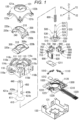
- a pair of the upper and lower arms 200 and 300, a lower portion of the operation shaft 400, the actuating member 500, the compression coil spring 600, the first and second sliders 700 and 800, the pusher 900, the first and second variable resistors 1000 and 1100, the pressing switch 1200, and the substrate 1300 are accommodated.
- an upper portion of the operation shaft 400 projects from the inside of the case 100 to the outside of the case 100 through the opening 121 of the cover 120.
- the front and rear slide parts 320a and 320b project from both front and rear ends of the bow-shaped part of the lower arm 300 to outer sides in the front-rear direction, and are arc-shaped projecting parts as viewed from the front-rear direction.
- the front and rear slide parts 320a and 320b are provided along a cylindrical surface coaxially arranged on the Y axis.
- the front slide part 320a is formed thicker than the rear slide part 320b.
- the engagement protrusion 330 is a protrusion having an ⁇ shape in cross section projecting downward from a central portion in the lateral direction on a lower surface of the rear slide part 320b.
- the rear slide part 320b is fitted slidably in the rear guide groove 102, while the front slide part 320a is slidably placed on a front arm hook 910 formed of an upper end surface provided along a cylindrical surface coaxially arranged on the Y axis of the pusher 900 in a state where its front end face slidably abuts on an inner surface of the front guide plate 119a, so that the lower arm 300 is bridged in the front-rear direction in a state of being orthogonal to the upper arm 200 right below the upper arm 200 in the case 100, and in that state, the lower arm 300 is supported movably in an arc shape in the lateral direction along the rear guide groove 102.
- the lower arm 300 moves along a cylindrical surface coaxially arranged on the Y axis.
- a front slide part 310a on a front end side of the lower arm 300 can be pressed and moved downward with a rear slide part 320b on a rear end side of the lower arm 300 as a fulcrum, by a slight gap (clearance) between the rear slide part 320b and the rear guide groove 102.
- a pair of the upper and lower arms 200 and 300 are supported movably in two directions orthogonal to each other in the case 100 having the bottom plate 131, and each has the elongated holes 210 and 310 extending in a direction orthogonal to a moving direction.
- the operation shaft 400 is a round rod-shaped member made of insulating synthetic resin having a diameter that is the same as a width of the elongated holes 210 and 310 of the upper and lower arms 200 and 300.
- the operation shaft 400 is arranged in the case 100 in a state where, as a middle portion in an axial direction of the operation shaft 400 penetrates the elongated holes 210 and 310 of the upper and lower arms 200 and 300, an upper end portion of the operation shaft 400 protruding above the upper arm 200 is inserted through the opening 121 of the cover 120 and protrudes to the outside of the case 100, and a lower end portion of the operation shaft 400 protruding downward of the lower arm 300 is inserted through an inner diameter of the receiving portion 112 of the body 110 and inserted into the operation shaft accommodation portion 111 of the body 110.
- the operation shaft 400 has the spherical trapezoidal portion 410 for rotatably supporting the lower end of the operation shaft 400 while also serving to prevent the operation shaft 400 from coming off, a stepped shaft hole 420 for supporting the actuating member 500 in the lower end of the operation shaft 400 so as to be movable in the axial direction of the operation shaft 400 in a state in which rotation around the axis of the operation shaft 400 is restricted, and also for providing the compression coil spring 600 between the operation shaft 400 and the actuating member 500, a pair of left and right engaging portions 430a and 430b for pressing and moving the lower arm 300 at the time of pressing and moving the operation shaft 400, an attaching hole 440 for screwing, for example, a disk-like key top, at the upper end of the operation shaft 400, and a two-sided cut portion 450 for locking the key top.
- the spherical trapezoidal portion 410 is arranged in the operation shaft accommodation portion 111 of the case 100.
- the spherical trapezoidal portion 410 is formed in an upward convex spherical trapezoidal shape, in which the diameter decreases upward, in the lower end portion of the operation shaft 400, a radius of an upper surface of the spherical trapezoidal portion 410 is equal to a radius of the operation shaft 400, and the spherical zone 411 of a side surface portion of the spherical trapezoidal portion 410 can be fitted to the receiving surface 112a of the receiving portion 112 of the case 100 from below.
- the stepped shaft hole 420 is provided coaxially with the operation shaft 400 in an axial center portion of the operation shaft 400, and has a DCled hole opened on a lower end surface (lower end surface of the operation shaft 400) of the spherical trapezoidal portion 410.
- the stepped shaft hole 420 has, from bottom to top, a shaft hole 421 having a rectangular cross section, a shaft hole 422 having a rectangular cross section smaller (having a smaller diameter) and longer than the shaft hole 421, a shaft hole 423 having a circular cross section that has the same diameter as the shaft hole 422, the same length as the shaft hole 422, and is capable of accommodating the compression coil spring 600, and a shaft hole 424 having a circular cross section that has a diameter smaller than the shaft hole 423 and is shorter than the shaft hole 423.
- Downward step surfaces 425, 426, and 427 are provided between the shaft hole 421 and the shaft hole 422, between the shaft hole 422 and the shaft hole 423, and between the shaft hole 423 and the shaft hole 424, respectively.
- the left and right engaging portions 430a and 430b are protrusions having a right-angled triangular cross-section projecting toward the left and right sides from an outer surface of the middle portion in the axial direction of the operation shaft 400 in the elongated hole 210 of the upper arm 200, and have engaging surfaces 431a and 431b facing each other with a slight gap (clearance) from above on left and right side edge portions of the elongated hole 310 in the curved upper surface 300a of the lower arm 300 in a bottom portion of the left and right engaging portions 430a and 430b.
- the engaging surfaces 431a and 431b are provided along a cylindrical surface coaxially arranged on the X axis, and are engaging surfaces facing downward that are curved along the curved upper surface 300a of the lower arm 300, are movable on a curved upper surface of the lower arm 300 when the operation shaft 400 rotates, and move the lower arm 300 along with the pressing movement of the operation shaft 400.
- the attaching hole 440 is a bottomed hole provided coaxially with the operation shaft 400 in the axial center portion of the operation shaft 400 and opened on the upper end surface of the operation shaft 400.
- the two-sided cut portion 450 is provided at the upper end of the operation shaft 400, and the upper end of the operation shaft 400 is formed in a shaft portion having an oblong cross section and a two-surface width.
- the actuating member 500 is made of insulating synthetic resin, and has a spherical trapezoidal portion 510, a stepped shaft portion 520, and a protrusion 530.
- the spherical trapezoidal portion 510 is provided at the lower end of the actuating member 500, and is placed in the central portion of the bottom plate 131 exposed in the operation shaft accommodation portion 111 of the case 100.
- the spherical trapezoidal portion 510 is formed in a downward convex spherical shape whose diameter decreases downward.
- the stepped shaft portion 520 is vertically provided at the center of the upper surface of the spherical trapezoidal portion 510, and is inserted in the shaft hole 420 of the operation shaft 400 so as to be movable in the axial direction of the operation shaft 400.
- the shaft portion 520 includes, from bottom to top, a square shaft portion 521 having a square cross section fitted in the shaft hole 421, a square shaft portion 522 having a square cross section fitted in the shaft hole 422, and a round shaft portion 523 having a circular cross section that is inserted into the shaft hole 423 together with the compression coil spring 600 in a state of being inserted into an inner diameter of the compression coil spring 600 and has an upper end portion as a spring guide fitted in the shaft hole 424.
- Upward step surfaces 524 and 525 are provided between the square shaft portion 521 and the square shaft portion 522 and between the square shaft portion 522 and the round shaft portion 523, respectively.
- Upper and lower wound ends are respectively brought into contact with the downward step surface 427 of the shaft hole 420 and the upward step surface 525 of the shaft portion 520, so as to bias the actuating member 500 downward along the axial direction of the operation shaft 400 in such a manner as pressing the spherical zone 511 and the lower surface 512 of the spherical trapezoidal portion 510 of the actuating member 500 against the bottom plate 131 of the case 100 from above, and to bias the operation shaft 400 upward along the axial direction in such a manner as pressing the spherical zone 411 of the spherical trapezoidal portion 410 of the operation shaft 400 from below against the receiving surface 112a of the receiving portion 112 of the case 100 from below.
- the first slider 700 is made of insulating synthetic resin.
- the first slider 700 has, as shown in Figs. 8 and 11 , a first slider main body 710, a first engagement piece 720, a first engagement groove 730, a first engagement protrusion 740, a first movable surface 750, and a first convex portion 760.
- the first slider main body 710 is a cuboid shaped block.
- the first engagement piece 720 is provided upright at the center of a flat upper surface of the first slider main body 710.
- the first engagement groove 730 is provided at the upper end of the first engagement piece 720.
- the first engagement protrusion 740 is a cylinder that projects downward from the central portion of the flat lower surface of the first slider main body 710.
- the first movable surface 750 is a flat upper surface of the first slider main body 710.
- the first movable surface 750 faces the first fixing surface 114b of the first slider accommodation portion 114, and is slidable in the front-rear direction along the first fixing surface 114b in a state of being elastically pressed against the first fixing surface 114b by an elastic force of a first contact described later.
- the first convex portion 760 is fitted to the first concave portion 114d provided in the first slider accommodation portion 114 when the first slider 700 is positioned at the neutral position.
- the second slider 800 is made of insulating synthetic resin.
- the second slider 800 has, as shown in Figs. 9 and 12 , a second slider main body 810, a second engagement piece 820, a second engagement groove 830, a second engagement protrusion 840, a second movable surface 850, and a second convex portion 860.
- the second slider main body 810 is a cuboid block.
- the second engagement piece 820 is provided upright at the center of the flat upper surface of the second slider main body 810.
- the second engagement groove 830 is provided at the upper end of the second engagement piece 820.
- the second engagement protrusion 840 is a cylinder that projects downward from the central portion of the flat lower surface of the second slider main body 810.
- the second movable surface 850 is a flat upper surface of the second slider main body 810.
- the second movable surface 850 faces the second fixing surface 115b of the second slider accommodation portion 115, and is slidable in the lateral direction along the second fixing surface 115b in a state of being elastically pressed against the second fixing surface 115b by an elastic force of a second contact described later.
- the second convex portion 860 is fitted to the second concave portion 115d provided in the second slider accommodation portion 115 when the second slider 800 is positioned at the neutral position, and is provided on each of the second movable surface 850 located closer to the front side relative to the second engagement piece 820 and the second movable surface 850 located closer to the rear side relative to the second engagement piece 820.
- the first variable resistor 1000 can detect a moving direction and a movement amount of the upper arm 200 by detecting a moving direction and a movement amount of the first slider 700 as a change in a resistance value.
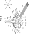
- the first variable resistor 1000 has a first contact 1010 and a first resistance circuit 1020 as shown in Figs. 1 , 6 , and 11 .
- the first resistance circuit 1020 is formed on the substrate 1300.
- the first contact 1010 is a metal plate spring piece.
- the first contact 1010 is fixed to the lower surface of the first slider main body 710 with the first engagement protrusion 740 interposed between them.
- the first contact 1010 is in contact with the first resistance circuit 1020 and makes the first resistance circuit 1020 conductive.
- the second variable resistor 1100 can detect a moving direction and a movement amount of the lower arm 300 by detecting a moving direction and a movement amount of the second slider 800 as a change in a resistance value.
- the second variable resistor 1100 has a second contact 1110 and a second resistance circuit 1120 as shown in Figs. 1 , 6 , and 12 .
- the second resistance circuit 1120 is formed on the substrate 1300.
- the second contact 1110 is a metal plate spring piece.
- the second contact 1110 is fixed to the lower surface of the second slider main body 810 with the second engagement protrusion 840 interposed between them.
- the second contact 1110 is in contact with the second resistance circuit 1120 and makes the second resistance circuit 1120 conductive.
- the pressing switch 1200 detects a pressing movement of the operation shaft 400.
- the pressing switch 1200 has a metal dome sheet 1210 and a switch circuit 1220 as shown in Figs. 1 , 5 , 6 , 9 , and 13 .
- the metal dome sheet 1210 has a cover sheet 1211 and a metal dome 1212.
- the cover sheet 1211 is a single-sided adhesive sheet.
- the metal dome 1212 is a movable contact made of an upward convex dome-shaped metal plate, and, as shown in Fig. 14 , biases the pusher 900 upward.
- the upper surface of the metal dome 1212 is adhered to the lower surface of the cover sheet 1211 to form the metal dome sheet 1210.
- the switch circuit 1220 has a central fixed contact 1221 and an outer fixed contact 1222.
- the central fixed contact 1221 has a circular shape and is formed on the upper surface of the substrate 1300 which is the lower surface of the pressing switch accommodation portion 116.
- the central fixed contact 1221 is arranged immediately below the pusher accommodation portion 117.
- the outer fixed contact 1222 is formed in the shape of a horseshoe to surround the central fixed contact 1221 with space and is formed on the upper surface of the substrate 1300.
- the metal dome sheet 1210 is adhered to the upper surface of the substrate 1300, which is the lower surface of the pressing switch accommodation portion 116, the metal dome 1212 is fixed on the outer fixed contact 1222 across the central fixed contact 1221, both ends in the lateral direction of the metal dome 1212 are in contact with the outer fixed contact 1222, and the top of the metal dome 1212 is separated from and faces the central fixed contact 1221 immediately below with a gap between them.
- the pusher 900 is a drive member for transmitting a pressing movement of the operation shaft 400 to the top of the metal dome 1212 together with the lower arm 300.
- the pusher 900 is formed of insulating synthetic resin in a rectangular plate shape, and has a front arm hook 910 on which the front slide part 320a of the lower arm 300 is placed slidably and a pressing portion 920 for pressing the pressing switch 1200.
- the pusher 900 is vertically movably supported in the case 100.
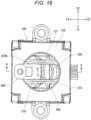
- the operation shaft 400 When the upper end of the operation shaft 400 in the neutral state is pressed in the left direction along the elongated hole 210 of the upper arm 200, the operation shaft 400 rotates around the center of curvature of the receiving surface 112a of the receiving portion 112 of the case 100 together with the actuating member 500 and tilts left along the elongated hole 210 of the upper arm 200 in a state where the operation shaft 400 is prevented from coming off by the receiving portion 112 of the case 100 as shown in Figs. 16 and 17 .
- the second convex portion 860 provided on the second slider 800 comes off the second concave portion 115d provided on the second slider accommodation portion 115 of the case 100 against the elastic force of the second contact 1110 of the second variable resistor 1100, and moves under the flat second fixing surface 115b located on the left side of the second concave portion 115d.
- the second variable resistor 1100 detects a moving direction and a movement amount of the second slider 800 as a moving direction and a movement amount of the lower arm 300. These are input from the tail portion 1320 of the substrate 1300 to a control unit of an electronic device via a connector and detected as a rotating direction and a rotation amount of the operation shaft 400 by the control unit.
- the operation shaft 400 When the pressing of the operation shaft 400 is released, the operation shaft 400 returns to the neutral state together with the actuating member 500 while the flat lower surface 512 of the downward convex spherical trapezoidal portion 510 of the actuating member 500 is returned to the horizontal state by the biasing force of the compression coil spring 600.
- the first slider 700 is moved so as to be guided to the neutral position immediately before its movement to the neutral position while the first concave portion 114d and the first convex portion 760 are fitted by the elastic force of the first contact 1010 of the first variable resistor 1000, and the first slider 700 is accurately returned to its neutral position without error while parts manufacturing tolerance and the like are absorbed.
- the operation shaft 400 is pressed down to separate the spherical zone 411 of the spherical trapezoidal portion 410 of the operation shaft 400 from the receiving surface 112a of the receiving portion 112 of the case 100 while pressing the shaft portion 520 of the actuating member 500 into the shaft hole 420 of the operation shaft 400 against the compression coil spring 600.
- the left and right sided edge portions of the elongated hole 310 on the curved upper surface 300a of the lower arm 300 are pressed downward by the left and right engaging surfaces 431a and 431b of the left and right engaging portions 430a and 430b of the operation shaft 400.
- the front slide part 310a on the front end side of the lower arm 300 slidably mounted on the upper end surface (front arm hook 910) of the pusher 900 is pressed and moved with the rear slide part 320b on the rear end side of the lower arm 300 slidably fitted in the rear guide groove 102 of the case 100 as a fulcrum.
- the pusher 900 moves downward.
- the top of the metal dome 1212 of the pressing switch 1200 is pressed down by the pressing portion 920 of the pusher 900, the top of the metal dome 1212 is elastically deformed in a downward convex shape with a click feeling and comes into contact with the central fixed contact 1221 of the switch circuit 1220 of the pressing switch 1200, and a switch-on state in which the central fixed contact 1221 and the outer fixed contact 1222 are electrically connected via the metal dome 1212 is established, so that the pressing movement of the operation shaft 400 is detected.
- the lower arm 300 functions as a "lever", and a fulcrum (the rear slide part 320b of the lower arm 300) is placed in a location that is on an outer side of a force application point (the left and right engaging portions 430a and 430b of the operation shaft 400) and an action point (the front slide part 310a of the lower arm 300) and close to the force application point, so that a small movement applied to the force application point becomes a large movement at the action point and a smaller force than the applied force is transmitted.
- a pressing movement amount of the operation shaft 400 for operating the pressing switch 1200 can be reduced, and an excellent click feeling can be obtained.
- the operation shaft 400 When the pressing of the operation shaft 400 is released, the operation shaft 400 is pressed up and moved so as to press the spherical zone 411 of the spherical trapezoidal portion 410 of the operation shaft 400 against the receiving surface 112a of the receiving portion 112 of the case 100 while the shaft portion 520 of the actuating member 500 is pulled out from the shaft hole 420 of the operation shaft 400 by the biasing force of the compression coil spring 600, and returns to the state before the pressing movement.
- the top of the metal dome 1212 returns to the original upward convex shape.
- the top of the metal dome 1212 is separated from the central fixed contact 1221 of the switch circuit 1220, and a switch-off state in which the central fixed contact 1221 and the outer fixed contact 1222 are electrically disconnected is established.
- the biasing force of the metal dome 1212 causes the pusher 900 to move upward and return to the original position, and the lower arm 300 returns to the original horizontal state accordingly.
- the operation shaft 400 is supported to be rotatable about the center of curvature of the receiving surface 112a. In this manner, since the operation shaft 400 is supported so as to be rotatable about the curvature center of the receiving surface 112a of the receiving portion 112 while being prevented from coming off by the receiving portion 112 positioned downward of the lower arm 300, the entire height of the device is reduced even if the rotation radius of the operation shaft 400 is increased, and the device can be downsized without lowering the strength of the operation shaft 400 and the lower arm 300.
- the actuating member 500 is supported at a lower end of the operation shaft 400 in a state of reducing rotation around an axis of the operation shaft 400 and is provided with the protrusion 530 projecting radially outward from an upper end of the downward convex spherical trapezoidal portion 510.
- the protrusion 530 is inserted to be movable vertically in the guide groove 113 that extends in the vertical direction on an inner wall of the case 100, so that rotation around an axis of the operation shaft 400 of the actuating member 500 is reduced. In this manner, rotation around an axis of the operation shaft 400 is reduced via the actuating member 500. Therefore, degree of freedom in a shape of the lower arm 300 is increased, the lower arm 300 can be downsized, and the device can be downsized.
- the case 100 having the bottom plate 131, a pair of the upper and lower arms 200 and 300 supported so as to be movable in two orthogonal directions in the inside of the case 100, the arms having the elongated holes 210 and 310 extending in a direction orthogonal to a moving direction, the operation shaft 400 that is rotatable in a state of penetrating the elongated holes 210 and 310, the actuating member 500 that is supported so as to be movable in an axial direction of the operation shaft 400 at a lower end of the operation shaft 400 projecting downward of the lower arm 300, and is provided with the downward convex spherical trapezoidal portion 510 whose diameter decreases downward, the compression coil spring 600 that is provided between the operation shaft 400 and the actuating member 500, and presses the downward convex spherical trapezoidal portion 510 against the bottom plate 131 to return the operation shaft 400 to a neutral state, and a plurality of the electric components 1000 and 1100 operated via the arms 200 and
- the upward convex spherical trapezoidal portion 410 whose diameter decreases upward is provided at a lower end of the operation shaft 400 projecting downward of the lower arm 300.
- the receiving portion 112 for the upward convex spherical trapezoidal portion 410 is provided in the case 100.
- the receiving portion 112 has the receiving surface 112a that is configured with a spherical surface having the same radius of curvature as radius of curvature of the spherical zone 411 of the upward convex spherical trapezoidal portion 410, the receiving surface against which the spherical zone 411 of the upward convex spherical trapezoidal portion 410 is pressed from downward by the compression coil spring 600.
- the operation shaft 400 is supported so as to be rotatable about the center of curvature of the receiving surface 112a.
- the lower arm 300 has the curved upper surface 300a provided along a cylindrical surface arranged coaxially on one horizontal axis (X axis) that passes through the center of curvature of the receiving surface 112a and extends in a moving direction of the lower arm 300.
- the operation shaft 400 is provided with the engaging portions 430a and 430b with the lower arm 300.
- the engaging portions 430a and 430b have the downward engaging surfaces 431a and 431b that are curved along the curved upper surface 300a of the lower arm 300 and are movable on the curved upper surface 300a of the lower arm 300 when the operation shaft 400 rotates.
- the operation shaft 400 in a state of being inserted through the elongated hole 310 of the lower arm 300 from downward is rotated by 90° so that the downward engaging surfaces 431a and 431b of the engaging portions 430a and 430b of the operation shaft 400 are arranged to face the curved upper surface 300a of the lower arm 300 for assembly. Accordingly, the operation shaft 400 and the lower arm 300 can be provided with enough strength, and the device can be downsized without lowering of the strength of the operation shaft 400 and the lower arm 300.
- the lower arm 300 does not have to be moved downward, and the pusher 900 does not have to be included. Therefore, in the lower arm 300, while the rear slide part 320b is slidably fitted into the rear guide groove 102, the front slide part 320a is slidably fitted to a front guide groove that is formed between an end surface of the front guide plate 119a provided with a front arm hook, which is provided in the front guide plate 119a in place of the front arm hook 910 formed of the upper end surface of the pusher 900, and an end surface of the front guide hole 122a of the cover 120.
- the lower arm 300 is bridged in the front-rear direction at a right angle to the upper arm 200 directly below the upper arm 200 in the case 100, and, in this state, is supported to be movable in an arc shape in the lateral direction along the front and rear guide grooves 102, and can move along a cylindrical surface coaxially arranged on the Y axis. Then, in a case where the pressing switch 1200 is not included, the engaging portions (the engaging portions 430a and 430b and the curved upper surface 300a) of the operation shaft 400 and the lower arm 300 prevent the operation shaft 400 from moving downward needlessly.
- the pusher 900 supported movably in the vertical direction and the pressing switch 1200 for detecting the pressing movement of the operation shaft 400 are further included in the case 100, the lower arm 300 moving downward with the pressing movement of the operation shaft 400 moves downward the pusher 900, and the pressing switch 1200 is operated via the pusher 900.
- the lower arm 300 has degree of freedom in a downward direction, and there is no possibility of interference between the downward engaging surfaces 431a and 431b of the engaging portions 430a and 430b of the operation shaft 400 and the curved upper surface 300a of the lower arm 300 even if the operation shaft is rotated by 90° and assembled. For this reason, a gap (clearance) between them is sufficiently reduced, and the pressing switch 1200 can be operated with a short stroke.
- a fitting shape between the shaft hole 420 of the operation shaft 400 and the shaft portion 520 of the actuating member 500 is a polygon as a section for locking the axial movement of the operation shaft 400 between the operation shaft 400 and the actuating member 500.
- spline fitting may be employed.
Landscapes
- Engineering & Computer Science (AREA)
- Microelectronics & Electronic Packaging (AREA)
- Physics & Mathematics (AREA)
- General Physics & Mathematics (AREA)
- Automation & Control Theory (AREA)
- Switches With Compound Operations (AREA)
Claims (1)
- Multidirektionale Eingabevorrichtung, umfassend:ein Gehäuse (100) mit einer Grundplatte (131);ein Paar von einem oberen und einem unteren Arm (200, 300), die so getragen werden, dass sie im Gehäuse (100) in zwei orthogonalen Richtungen bewegbar sind, wobei das Paar von einem oberen und einem unteren Arm (200, 300) jeweils ein längliches Loch (210, 310) aufweist, das sich in einer Richtung orthogonal zu einer Bewegungsrichtung erstreckt;eine Arbeitswelle (400), die in einem Zustand des Durchlaufens jedes länglichen Lochs (210, 310) drehbar ist;ein Betätigungselement (500), das so getragen wird, dass es in einer axialen Richtung der Arbeitswelle (400) an einem unteren Ende der Arbeitswelle (400), unterhalb des unteren Armes (300) vorstehend, bewegbar ist und mit einem sich abwärts erstreckenden, konvexen, runden, trapezförmigen Abschnitt (510), dessen Durchmesser sich nach unten verringert, versehen ist;eine Schraubendruckfeder (600), die zwischen der Arbeitswelle (400) und dem Betätigungselement (500) vorgesehen ist und den sich abwärts erstreckenden, konvexen, runden, trapezförmigen Abschnitt (510) gegen die untere Platte (131) drückt, um die Arbeitswelle (400) in einen Neutralzustand zurückzuführen; undeine Vielzahl von elektrischen Komponenten (1000, 1100), die durch Drehung der Arbeitswelle (400) über jeden Arm (200, 300) betätigt werden, wobeiein sich aufwärts erstreckender, konvexer, runder, trapezförmiger Abschnitt (410), dessen Durchmesser sich nach oben verringert, an einem unteren Ende der unterhalb des unteren Arms (300) vorstehenden Arbeitswelle (400) bereitgestellt ist,in dem Gehäuse (100) ein Aufnahmeabschnitt (112) für den sich aufwärts erstreckenden, konvexen, runden, trapezförmigen Abschnitt (410) bereitgestellt ist,der Aufnahmeabschnitt (112) eine Aufnahmefläche (112a) aufweist, die mit einer runden Fläche ausgestaltet ist, die einen Wölbungsradius aufweist, der mit einem Wölbungsradius eines runden Bereichs (411) des sich aufwärts erstreckenden, konvexen, runden, trapezförmigen Abschnitts (410) identisch ist, wobei gegen die Aufnahmefläche (112a) durch die Schraubendruckfeder (600) von unten ein runder Bereich (411) des sich aufwärts erstreckenden, konvexen, runden, trapezförmigen Abschnitts (410) gedrückt wird, unddie Arbeitswelle (400) so abgestützt ist, dass sie um eine Mitte der Wölbung der Aufnahmefläche (112a) drehbar ist.
Priority Applications (1)
| Application Number | Priority Date | Filing Date | Title |
|---|---|---|---|
| EP23160621.1A EP4220678B1 (de) | 2018-09-25 | 2019-08-26 | Multidirektionale eingabevorrichtung |
Applications Claiming Priority (2)
| Application Number | Priority Date | Filing Date | Title |
|---|---|---|---|
| JP2018178357A JP7021040B2 (ja) | 2018-09-25 | 2018-09-25 | 多方向入力装置 |
| EP19193553.5A EP3629353B1 (de) | 2018-09-25 | 2019-08-26 | Multidirektionale eingabevorrichtung |
Related Parent Applications (2)
| Application Number | Title | Priority Date | Filing Date |
|---|---|---|---|
| EP19193553.5A Division EP3629353B1 (de) | 2018-09-25 | 2019-08-26 | Multidirektionale eingabevorrichtung |
| EP19193553.5A Division-Into EP3629353B1 (de) | 2018-09-25 | 2019-08-26 | Multidirektionale eingabevorrichtung |
Related Child Applications (2)
| Application Number | Title | Priority Date | Filing Date |
|---|---|---|---|
| EP23160621.1A Division EP4220678B1 (de) | 2018-09-25 | 2019-08-26 | Multidirektionale eingabevorrichtung |
| EP23160621.1A Division-Into EP4220678B1 (de) | 2018-09-25 | 2019-08-26 | Multidirektionale eingabevorrichtung |
Publications (3)
| Publication Number | Publication Date |
|---|---|
| EP4084036A2 EP4084036A2 (de) | 2022-11-02 |
| EP4084036A3 EP4084036A3 (de) | 2023-01-25 |
| EP4084036B1 true EP4084036B1 (de) | 2025-07-02 |
Family
ID=67766063
Family Applications (3)
| Application Number | Title | Priority Date | Filing Date |
|---|---|---|---|
| EP19193553.5A Active EP3629353B1 (de) | 2018-09-25 | 2019-08-26 | Multidirektionale eingabevorrichtung |
| EP23160621.1A Active EP4220678B1 (de) | 2018-09-25 | 2019-08-26 | Multidirektionale eingabevorrichtung |
| EP22170295.4A Active EP4084036B1 (de) | 2018-09-25 | 2019-08-26 | Multidirektionale eingabevorrichtung |
Family Applications Before (2)
| Application Number | Title | Priority Date | Filing Date |
|---|---|---|---|
| EP19193553.5A Active EP3629353B1 (de) | 2018-09-25 | 2019-08-26 | Multidirektionale eingabevorrichtung |
| EP23160621.1A Active EP4220678B1 (de) | 2018-09-25 | 2019-08-26 | Multidirektionale eingabevorrichtung |
Country Status (3)
| Country | Link |
|---|---|
| US (1) | US10768658B2 (de) |
| EP (3) | EP3629353B1 (de) |
| JP (1) | JP7021040B2 (de) |
Families Citing this family (13)
| Publication number | Priority date | Publication date | Assignee | Title |
|---|---|---|---|---|
| JP7016666B2 (ja) * | 2017-10-20 | 2022-02-07 | 日本電産サンキョー株式会社 | コイルユニットの製造方法 |
| EP3701216A4 (de) | 2017-10-27 | 2021-09-22 | Fluidity Technologies, Inc. | Kardanaufhängung mit mehreren achsen für eine steuerung zur bereitstellung von taktiler rückmeldung für den null-befehl |
| US11599107B2 (en) | 2019-12-09 | 2023-03-07 | Fluidity Technologies Inc. | Apparatus, methods and systems for remote or onboard control of flights |
| JP7301730B2 (ja) * | 2019-12-17 | 2023-07-03 | アルプスアルパイン株式会社 | 多方向入力装置 |
| JP7349556B2 (ja) * | 2020-03-16 | 2023-09-22 | アルプスアルパイン株式会社 | 操作装置 |
| CN115552350A (zh) * | 2020-06-03 | 2022-12-30 | 阿尔卑斯阿尔派株式会社 | 操作装置 |
| TWI742833B (zh) * | 2020-09-03 | 2021-10-11 | 香港商冠捷投資有限公司 | 電子裝置及其按鍵總成 |
| CN112490053B (zh) * | 2020-11-19 | 2024-07-02 | 深圳市致尚科技股份有限公司 | 多方向输入装置和游戏机 |
| US20220269300A1 (en) * | 2021-02-25 | 2022-08-25 | Fluidity Technologies Inc. | Multi-axis gimbal and controller comprising same |
| US11688568B2 (en) | 2021-03-15 | 2023-06-27 | Essex Industries, Inc. | Five-position switch |
| JP7198871B2 (ja) * | 2021-05-28 | 2023-01-04 | 株式会社バンダイ | 模型部品、及び関節構造 |
| US11662835B1 (en) | 2022-04-26 | 2023-05-30 | Fluidity Technologies Inc. | System and methods for controlling motion of a target object and providing discrete, directional tactile feedback |
| US11696633B1 (en) | 2022-04-26 | 2023-07-11 | Fluidity Technologies Inc. | System and methods for controlling motion of a target object and providing discrete, directional tactile feedback |
Family Cites Families (12)
| Publication number | Priority date | Publication date | Assignee | Title |
|---|---|---|---|---|
| JPH0555433U (ja) * | 1991-12-26 | 1993-07-23 | ナイルス部品株式会社 | 多方向スイッチ |
| JP3752389B2 (ja) | 1998-10-05 | 2006-03-08 | アルプス電気株式会社 | 多方向入力装置 |
| JP3688936B2 (ja) * | 1999-05-07 | 2005-08-31 | ホシデン株式会社 | 多方向入力装置 |
| JP2001250456A (ja) * | 2000-03-07 | 2001-09-14 | Alps Electric Co Ltd | 多方向入力装置 |
| US6504115B2 (en) | 2000-03-07 | 2003-01-07 | Alps Electric Co., Ltd. | Multidirectional input device |
| JP3925219B2 (ja) * | 2002-01-30 | 2007-06-06 | ミツミ電機株式会社 | ジョイスティック |
| JP4057862B2 (ja) * | 2002-08-27 | 2008-03-05 | アルプス電気株式会社 | 複合操作型入力装置 |
| JP4418399B2 (ja) | 2004-08-09 | 2010-02-17 | ホシデン株式会社 | 多接点入力装置 |
| KR101425500B1 (ko) * | 2006-02-21 | 2014-08-01 | 호시덴 가부시기가이샤 | 스위치 |
| JP6336760B2 (ja) * | 2014-01-16 | 2018-06-06 | ホシデン株式会社 | 多方向入力装置 |
| JP2015210995A (ja) * | 2014-04-30 | 2015-11-24 | 日本電産コパル株式会社 | 多方向入力装置及び情報処理装置 |
| CN204792582U (zh) * | 2015-07-27 | 2015-11-18 | 东莞市凯华电子有限公司 | 新型游戏摇杆开关 |
-
2018
- 2018-09-25 JP JP2018178357A patent/JP7021040B2/ja active Active
-
2019
- 2019-08-07 US US16/534,222 patent/US10768658B2/en active Active
- 2019-08-26 EP EP19193553.5A patent/EP3629353B1/de active Active
- 2019-08-26 EP EP23160621.1A patent/EP4220678B1/de active Active
- 2019-08-26 EP EP22170295.4A patent/EP4084036B1/de active Active
Also Published As
| Publication number | Publication date |
|---|---|
| EP4220678A1 (de) | 2023-08-02 |
| JP2020053123A (ja) | 2020-04-02 |
| EP4084036A2 (de) | 2022-11-02 |
| JP7021040B2 (ja) | 2022-02-16 |
| EP4084036A3 (de) | 2023-01-25 |
| US20200097037A1 (en) | 2020-03-26 |
| US10768658B2 (en) | 2020-09-08 |
| EP3629353B1 (de) | 2022-10-26 |
| EP3629353A1 (de) | 2020-04-01 |
| EP4220678B1 (de) | 2024-05-15 |
Similar Documents
| Publication | Publication Date | Title |
|---|---|---|
| EP4084036B1 (de) | Multidirektionale eingabevorrichtung | |
| CA2642326C (en) | Switch | |
| US7288732B2 (en) | Multidirectional input device | |
| US11364435B2 (en) | Operation device | |
| EP3086349B1 (de) | Multidirektionale eingabevorrichtung | |
| JP7235630B2 (ja) | 多方向入力装置 | |
| EP3780052B1 (de) | Schaltvorrichtung | |
| JP2000243187A (ja) | 多方向入力装置 | |
| EP3582243B1 (de) | Vierwegeschalter mit fehlfunktionverhinderungsstruktur | |
| JP2013108881A (ja) | 多方向入力装置 | |
| JP4937994B2 (ja) | 多方向スライド式スイッチ | |
| JP6993942B2 (ja) | 多方向入力装置 | |
| US7301111B2 (en) | Slide switch | |
| JP7096089B2 (ja) | 多方向入力装置 | |
| JP2024158791A (ja) | 多方向入力装置 | |
| JP2007329070A (ja) | 多方向入力装置 | |
| JP2006294303A (ja) | 多方向入力装置 | |
| JP6204232B2 (ja) | 入力装置 | |
| JP2002190237A (ja) | 多方向スイッチ | |
| KR20040041760A (ko) | 4방향 스위치 | |
| JP2010010081A (ja) | 多方向入力装置 |
Legal Events
| Date | Code | Title | Description |
|---|---|---|---|
| PUAI | Public reference made under article 153(3) epc to a published international application that has entered the european phase |
Free format text: ORIGINAL CODE: 0009012 |
|
| STAA | Information on the status of an ep patent application or granted ep patent |
Free format text: STATUS: REQUEST FOR EXAMINATION WAS MADE |
|
| 17P | Request for examination filed |
Effective date: 20220530 |
|
| AC | Divisional application: reference to earlier application |
Ref document number: 3629353 Country of ref document: EP Kind code of ref document: P |
|
| AK | Designated contracting states |
Kind code of ref document: A2 Designated state(s): AL AT BE BG CH CY CZ DE DK EE ES FI FR GB GR HR HU IE IS IT LI LT LU LV MC MK MT NL NO PL PT RO RS SE SI SK SM TR |
|
| PUAL | Search report despatched |
Free format text: ORIGINAL CODE: 0009013 |
|
| AK | Designated contracting states |
Kind code of ref document: A3 Designated state(s): AL AT BE BG CH CY CZ DE DK EE ES FI FR GB GR HR HU IE IS IT LI LT LU LV MC MK MT NL NO PL PT RO RS SE SI SK SM TR |
|
| RIC1 | Information provided on ipc code assigned before grant |
Ipc: H01H 25/00 20060101ALI20221220BHEP Ipc: H01H 25/04 20060101AFI20221220BHEP |
|
| GRAP | Despatch of communication of intention to grant a patent |
Free format text: ORIGINAL CODE: EPIDOSNIGR1 |
|
| STAA | Information on the status of an ep patent application or granted ep patent |
Free format text: STATUS: GRANT OF PATENT IS INTENDED |
|
| INTG | Intention to grant announced |
Effective date: 20250327 |
|
| GRAS | Grant fee paid |
Free format text: ORIGINAL CODE: EPIDOSNIGR3 |
|
| GRAA | (expected) grant |
Free format text: ORIGINAL CODE: 0009210 |
|
| STAA | Information on the status of an ep patent application or granted ep patent |
Free format text: STATUS: THE PATENT HAS BEEN GRANTED |
|
| AC | Divisional application: reference to earlier application |
Ref document number: 3629353 Country of ref document: EP Kind code of ref document: P |
|
| AK | Designated contracting states |
Kind code of ref document: B1 Designated state(s): AL AT BE BG CH CY CZ DE DK EE ES FI FR GB GR HR HU IE IS IT LI LT LU LV MC MK MT NL NO PL PT RO RS SE SI SK SM TR |
|
| REG | Reference to a national code |
Ref country code: GB Ref legal event code: FG4D |
|
| REG | Reference to a national code |
Ref country code: CH Ref legal event code: EP |
|
| REG | Reference to a national code |
Ref country code: DE Ref legal event code: R096 Ref document number: 602019072169 Country of ref document: DE |
|
| REG | Reference to a national code |
Ref country code: IE Ref legal event code: FG4D |
|
| PGFP | Annual fee paid to national office [announced via postgrant information from national office to epo] |
Ref country code: DE Payment date: 20250807 Year of fee payment: 7 |
|
| PGFP | Annual fee paid to national office [announced via postgrant information from national office to epo] |
Ref country code: GB Payment date: 20250814 Year of fee payment: 7 |
|
| PGFP | Annual fee paid to national office [announced via postgrant information from national office to epo] |
Ref country code: FR Payment date: 20250814 Year of fee payment: 7 |
|
| REG | Reference to a national code |
Ref country code: NL Ref legal event code: MP Effective date: 20250702 |
|
| PG25 | Lapsed in a contracting state [announced via postgrant information from national office to epo] |
Ref country code: PT Free format text: LAPSE BECAUSE OF FAILURE TO SUBMIT A TRANSLATION OF THE DESCRIPTION OR TO PAY THE FEE WITHIN THE PRESCRIBED TIME-LIMIT Effective date: 20251103 |
|
| PG25 | Lapsed in a contracting state [announced via postgrant information from national office to epo] |
Ref country code: NL Free format text: LAPSE BECAUSE OF FAILURE TO SUBMIT A TRANSLATION OF THE DESCRIPTION OR TO PAY THE FEE WITHIN THE PRESCRIBED TIME-LIMIT Effective date: 20250702 |
|
| REG | Reference to a national code |
Ref country code: AT Ref legal event code: MK05 Ref document number: 1810261 Country of ref document: AT Kind code of ref document: T Effective date: 20250702 |
|
| PG25 | Lapsed in a contracting state [announced via postgrant information from national office to epo] |
Ref country code: IS Free format text: LAPSE BECAUSE OF FAILURE TO SUBMIT A TRANSLATION OF THE DESCRIPTION OR TO PAY THE FEE WITHIN THE PRESCRIBED TIME-LIMIT Effective date: 20251102 |
|
| PG25 | Lapsed in a contracting state [announced via postgrant information from national office to epo] |
Ref country code: NO Free format text: LAPSE BECAUSE OF FAILURE TO SUBMIT A TRANSLATION OF THE DESCRIPTION OR TO PAY THE FEE WITHIN THE PRESCRIBED TIME-LIMIT Effective date: 20251002 |
|
| REG | Reference to a national code |
Ref country code: LT Ref legal event code: MG9D |
|
| PG25 | Lapsed in a contracting state [announced via postgrant information from national office to epo] |
Ref country code: AT Free format text: LAPSE BECAUSE OF FAILURE TO SUBMIT A TRANSLATION OF THE DESCRIPTION OR TO PAY THE FEE WITHIN THE PRESCRIBED TIME-LIMIT Effective date: 20250702 |
|
| PG25 | Lapsed in a contracting state [announced via postgrant information from national office to epo] |
Ref country code: FI Free format text: LAPSE BECAUSE OF FAILURE TO SUBMIT A TRANSLATION OF THE DESCRIPTION OR TO PAY THE FEE WITHIN THE PRESCRIBED TIME-LIMIT Effective date: 20250702 |
|
| PG25 | Lapsed in a contracting state [announced via postgrant information from national office to epo] |
Ref country code: HR Free format text: LAPSE BECAUSE OF FAILURE TO SUBMIT A TRANSLATION OF THE DESCRIPTION OR TO PAY THE FEE WITHIN THE PRESCRIBED TIME-LIMIT Effective date: 20250702 |
|
| PG25 | Lapsed in a contracting state [announced via postgrant information from national office to epo] |
Ref country code: GR Free format text: LAPSE BECAUSE OF FAILURE TO SUBMIT A TRANSLATION OF THE DESCRIPTION OR TO PAY THE FEE WITHIN THE PRESCRIBED TIME-LIMIT Effective date: 20251003 |
|
| PG25 | Lapsed in a contracting state [announced via postgrant information from national office to epo] |
Ref country code: SE Free format text: LAPSE BECAUSE OF FAILURE TO SUBMIT A TRANSLATION OF THE DESCRIPTION OR TO PAY THE FEE WITHIN THE PRESCRIBED TIME-LIMIT Effective date: 20250702 Ref country code: CZ Free format text: LAPSE BECAUSE OF FAILURE TO SUBMIT A TRANSLATION OF THE DESCRIPTION OR TO PAY THE FEE WITHIN THE PRESCRIBED TIME-LIMIT Effective date: 20250702 |
|
| PG25 | Lapsed in a contracting state [announced via postgrant information from national office to epo] |
Ref country code: LV Free format text: LAPSE BECAUSE OF FAILURE TO SUBMIT A TRANSLATION OF THE DESCRIPTION OR TO PAY THE FEE WITHIN THE PRESCRIBED TIME-LIMIT Effective date: 20250702 |
|
| PG25 | Lapsed in a contracting state [announced via postgrant information from national office to epo] |
Ref country code: BG Free format text: LAPSE BECAUSE OF FAILURE TO SUBMIT A TRANSLATION OF THE DESCRIPTION OR TO PAY THE FEE WITHIN THE PRESCRIBED TIME-LIMIT Effective date: 20250702 Ref country code: PL Free format text: LAPSE BECAUSE OF FAILURE TO SUBMIT A TRANSLATION OF THE DESCRIPTION OR TO PAY THE FEE WITHIN THE PRESCRIBED TIME-LIMIT Effective date: 20250702 |
|
| PG25 | Lapsed in a contracting state [announced via postgrant information from national office to epo] |
Ref country code: RS Free format text: LAPSE BECAUSE OF FAILURE TO SUBMIT A TRANSLATION OF THE DESCRIPTION OR TO PAY THE FEE WITHIN THE PRESCRIBED TIME-LIMIT Effective date: 20251002 |
|
| PG25 | Lapsed in a contracting state [announced via postgrant information from national office to epo] |
Ref country code: ES Free format text: LAPSE BECAUSE OF FAILURE TO SUBMIT A TRANSLATION OF THE DESCRIPTION OR TO PAY THE FEE WITHIN THE PRESCRIBED TIME-LIMIT Effective date: 20250702 |
|
| PG25 | Lapsed in a contracting state [announced via postgrant information from national office to epo] |
Ref country code: RO Free format text: LAPSE BECAUSE OF FAILURE TO SUBMIT A TRANSLATION OF THE DESCRIPTION OR TO PAY THE FEE WITHIN THE PRESCRIBED TIME-LIMIT Effective date: 20250702 |
|
| REG | Reference to a national code |
Ref country code: CH Ref legal event code: H13 Free format text: ST27 STATUS EVENT CODE: U-0-0-H10-H13 (AS PROVIDED BY THE NATIONAL OFFICE) Effective date: 20260324 |
|
| PG25 | Lapsed in a contracting state [announced via postgrant information from national office to epo] |
Ref country code: SM Free format text: LAPSE BECAUSE OF FAILURE TO SUBMIT A TRANSLATION OF THE DESCRIPTION OR TO PAY THE FEE WITHIN THE PRESCRIBED TIME-LIMIT Effective date: 20250702 |
|
| PG25 | Lapsed in a contracting state [announced via postgrant information from national office to epo] |
Ref country code: DK Free format text: LAPSE BECAUSE OF FAILURE TO SUBMIT A TRANSLATION OF THE DESCRIPTION OR TO PAY THE FEE WITHIN THE PRESCRIBED TIME-LIMIT Effective date: 20250702 |
|
| PG25 | Lapsed in a contracting state [announced via postgrant information from national office to epo] |
Ref country code: LU Free format text: LAPSE BECAUSE OF NON-PAYMENT OF DUE FEES Effective date: 20250826 Ref country code: IT Free format text: LAPSE BECAUSE OF FAILURE TO SUBMIT A TRANSLATION OF THE DESCRIPTION OR TO PAY THE FEE WITHIN THE PRESCRIBED TIME-LIMIT Effective date: 20250702 |
|
| PG25 | Lapsed in a contracting state [announced via postgrant information from national office to epo] |
Ref country code: CH Free format text: LAPSE BECAUSE OF NON-PAYMENT OF DUE FEES Effective date: 20250831 |
|
| PG25 | Lapsed in a contracting state [announced via postgrant information from national office to epo] |
Ref country code: EE Free format text: LAPSE BECAUSE OF FAILURE TO SUBMIT A TRANSLATION OF THE DESCRIPTION OR TO PAY THE FEE WITHIN THE PRESCRIBED TIME-LIMIT Effective date: 20250702 Ref country code: SK Free format text: LAPSE BECAUSE OF FAILURE TO SUBMIT A TRANSLATION OF THE DESCRIPTION OR TO PAY THE FEE WITHIN THE PRESCRIBED TIME-LIMIT Effective date: 20250702 |