EP4085523B1 - Procédé de commande d'un générateur à induction et agencement de commande d'un générateur à induction - Google Patents
Procédé de commande d'un générateur à induction et agencement de commande d'un générateur à induction Download PDFInfo
- Publication number
- EP4085523B1 EP4085523B1 EP21711752.2A EP21711752A EP4085523B1 EP 4085523 B1 EP4085523 B1 EP 4085523B1 EP 21711752 A EP21711752 A EP 21711752A EP 4085523 B1 EP4085523 B1 EP 4085523B1
- Authority
- EP
- European Patent Office
- Prior art keywords
- rotor
- frequency
- grid frequency
- actual
- generator
- Prior art date
- Legal status (The legal status is an assumption and is not a legal conclusion. Google has not performed a legal analysis and makes no representation as to the accuracy of the status listed.)
- Active
Links
Images
Classifications
-
- H—ELECTRICITY
- H02—GENERATION; CONVERSION OR DISTRIBUTION OF ELECTRIC POWER
- H02P—CONTROL OR REGULATION OF ELECTRIC MOTORS, ELECTRIC GENERATORS OR DYNAMO-ELECTRIC CONVERTERS; CONTROLLING TRANSFORMERS, REACTORS OR CHOKE COILS
- H02P9/00—Arrangements for controlling electric generators for the purpose of obtaining a desired output
- H02P9/007—Control circuits for doubly fed generators
-
- H—ELECTRICITY
- H02—GENERATION; CONVERSION OR DISTRIBUTION OF ELECTRIC POWER
- H02P—CONTROL OR REGULATION OF ELECTRIC MOTORS, ELECTRIC GENERATORS OR DYNAMO-ELECTRIC CONVERTERS; CONTROLLING TRANSFORMERS, REACTORS OR CHOKE COILS
- H02P23/00—Arrangements or methods for the control of AC motors characterised by a control method other than vector control
- H02P23/08—Controlling based on slip frequency, e.g. adding slip frequency and speed proportional frequency
-
- H—ELECTRICITY
- H02—GENERATION; CONVERSION OR DISTRIBUTION OF ELECTRIC POWER
- H02P—CONTROL OR REGULATION OF ELECTRIC MOTORS, ELECTRIC GENERATORS OR DYNAMO-ELECTRIC CONVERTERS; CONTROLLING TRANSFORMERS, REACTORS OR CHOKE COILS
- H02P9/00—Arrangements for controlling electric generators for the purpose of obtaining a desired output
- H02P9/10—Control effected upon generator excitation circuit to reduce harmful effects of overloads or transients, e.g. sudden application of load, sudden removal of load, sudden change of load
- H02P9/107—Control effected upon generator excitation circuit to reduce harmful effects of overloads or transients, e.g. sudden application of load, sudden removal of load, sudden change of load for limiting effects of overloads
-
- F—MECHANICAL ENGINEERING; LIGHTING; HEATING; WEAPONS; BLASTING
- F03—MACHINES OR ENGINES FOR LIQUIDS; WIND, SPRING, OR WEIGHT MOTORS; PRODUCING MECHANICAL POWER OR A REACTIVE PROPULSIVE THRUST, NOT OTHERWISE PROVIDED FOR
- F03D—WIND MOTORS
- F03D7/00—Controlling wind motors
- F03D7/02—Controlling wind motors the wind motors having rotation axis substantially parallel to the air flow entering the rotor
- F03D7/0272—Controlling wind motors the wind motors having rotation axis substantially parallel to the air flow entering the rotor by measures acting on the electrical generator
-
- F—MECHANICAL ENGINEERING; LIGHTING; HEATING; WEAPONS; BLASTING
- F03—MACHINES OR ENGINES FOR LIQUIDS; WIND, SPRING, OR WEIGHT MOTORS; PRODUCING MECHANICAL POWER OR A REACTIVE PROPULSIVE THRUST, NOT OTHERWISE PROVIDED FOR
- F03D—WIND MOTORS
- F03D7/00—Controlling wind motors
- F03D7/02—Controlling wind motors the wind motors having rotation axis substantially parallel to the air flow entering the rotor
- F03D7/028—Controlling wind motors the wind motors having rotation axis substantially parallel to the air flow entering the rotor controlling wind motor output power
- F03D7/0284—Controlling wind motors the wind motors having rotation axis substantially parallel to the air flow entering the rotor controlling wind motor output power in relation to the state of the electric grid
-
- F—MECHANICAL ENGINEERING; LIGHTING; HEATING; WEAPONS; BLASTING
- F05—INDEXING SCHEMES RELATING TO ENGINES OR PUMPS IN VARIOUS SUBCLASSES OF CLASSES F01-F04
- F05B—INDEXING SCHEME RELATING TO WIND, SPRING, WEIGHT, INERTIA OR LIKE MOTORS, TO MACHINES OR ENGINES FOR LIQUIDS COVERED BY SUBCLASSES F03B, F03D AND F03G
- F05B2270/00—Control
- F05B2270/30—Control parameters, e.g. input parameters
- F05B2270/337—Electrical grid status parameters, e.g. voltage, frequency or power demand
-
- H—ELECTRICITY
- H02—GENERATION; CONVERSION OR DISTRIBUTION OF ELECTRIC POWER
- H02P—CONTROL OR REGULATION OF ELECTRIC MOTORS, ELECTRIC GENERATORS OR DYNAMO-ELECTRIC CONVERTERS; CONTROLLING TRANSFORMERS, REACTORS OR CHOKE COILS
- H02P2101/00—Special adaptation of control arrangements for generators
- H02P2101/10—Special adaptation of control arrangements for generators for water-driven turbines
-
- H—ELECTRICITY
- H02—GENERATION; CONVERSION OR DISTRIBUTION OF ELECTRIC POWER
- H02P—CONTROL OR REGULATION OF ELECTRIC MOTORS, ELECTRIC GENERATORS OR DYNAMO-ELECTRIC CONVERTERS; CONTROLLING TRANSFORMERS, REACTORS OR CHOKE COILS
- H02P2103/00—Controlling arrangements characterised by the type of generator
- H02P2103/10—Controlling arrangements characterised by the type of generator of the asynchronous type
-
- H—ELECTRICITY
- H02—GENERATION; CONVERSION OR DISTRIBUTION OF ELECTRIC POWER
- H02P—CONTROL OR REGULATION OF ELECTRIC MOTORS, ELECTRIC GENERATORS OR DYNAMO-ELECTRIC CONVERTERS; CONTROLLING TRANSFORMERS, REACTORS OR CHOKE COILS
- H02P2207/00—Indexing scheme relating to controlling arrangements characterised by the type of motor
- H02P2207/07—Doubly fed machines receiving two supplies both on the stator only wherein the power supply is fed to different sets of stator windings or to rotor and stator windings
-
- Y—GENERAL TAGGING OF NEW TECHNOLOGICAL DEVELOPMENTS; GENERAL TAGGING OF CROSS-SECTIONAL TECHNOLOGIES SPANNING OVER SEVERAL SECTIONS OF THE IPC; TECHNICAL SUBJECTS COVERED BY FORMER USPC CROSS-REFERENCE ART COLLECTIONS [XRACs] AND DIGESTS
- Y02—TECHNOLOGIES OR APPLICATIONS FOR MITIGATION OR ADAPTATION AGAINST CLIMATE CHANGE
- Y02E—REDUCTION OF GREENHOUSE GAS [GHG] EMISSIONS, RELATED TO ENERGY GENERATION, TRANSMISSION OR DISTRIBUTION
- Y02E10/00—Energy generation through renewable energy sources
- Y02E10/70—Wind energy
- Y02E10/72—Wind turbines with rotation axis in wind direction
Definitions
- the present invention relates to a method and to an arrangement of controlling an induction generator connected to a utility grid, in particular during changing grid frequency. Furthermore, the present invention relates to a wind turbine including an induction generator and the arrangement.
- Deviations of the frequency from the nominal grid frequency may however affect the operation of components of the wind turbine, such as generators and/or converters included in the wind turbine.
- induction generators may be affected regarding operation in case of frequency changes.
- induction generators and/or converters connected to the induction generator may have been over-specified or over-dimensioned in order to allow operation over a particular grid frequency range around a nominal grid frequency.
- over-dimensioning the components for example regarding rated power, rated current or rated voltage
- these components were able to be operated at differing frequencies.
- requirement envelopes have been calculated to define ratings of the components for a particular frequency range of expected variations from the nominal grid frequency.
- the conventionally applied methods and systems require a complex heavy equipment and heavy associated high costs.
- An induction generator is an asynchronous generator which generates alternating current when its rotor shaft is rotating relative to stator windings.
- the rotor needs to rotate faster than the synchronous speed in order to output rotor power having the desired frequency.
- the so called synchronous speed corresponds to the frequency of the AC power to be provided to the utility grid.
- excitation signals or excitation power also referred to as control signals
- the relative difference between synchronous speed and the operating speed is called the slip usually expressed as percent of the synchronous speed.
- the actual grid frequency is determined as averaging and/or filtering an instantaneous grid frequency over a predetermined time range, in particular spanning between 1 min and 10 min.
- the actual grid frequency deviates from the nominal frequency by less than 5 %, or less than 3 %, and/or wherein the induction generator includes a, in particular three-phase, doubly-fed induction generator and/or a squirrel cage type generator.
- the induction generator is driven by a rotating shaft of a wind turbine, in particular coupled via a gear box to a main shaft at which plural rotor blades are connected.
- the gear box may have a transformation ratio such that a typical rotational speed of a main shaft of the wind turbine is converted too roughly the synchronous speed times the slip corresponding to the nominal frequency of the utility grid.
- a wind turbine is provided according to an embodiment of the present invention, which includes an induction generator driven by wind energy, the generator having rotor windings and an arrangement according to the precedingly described embodiment.
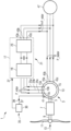
- the wind turbine 1 according to an embodiment of the present invention illustrated in the Figure includes a doubly-fed induction generator 3.
- the induction generator 3 is driven by a secondary shaft 5 which is coupled to a gear box 7.
- the gear box 7 converts a relatively low rotational speed of a main shaft 9 of the wind turbine to a relatively high rotational speed of the secondary shaft 5.
- plural rotor blades 11 are connected, which are driven by impacting wind 13.
- a not illustrated nacelle mounted on top of a wind turbine power harbours the generator 3, the shafts 9, 5, the gear box 7 and a converter 17.
- the output terminals 43a, 43b, 43c of the converter 17 are connected with output terminals 45a, 45b, 45c of the stator windings 13.
- the stator power P_stator as well as the rotor power P_rotor are connected to a step-up transformer and this is connected to the utility grid 47 where other wind turbines are also connected.
- the utility grid 47 is intended to be operated at a nominal frequency f0. However, due to disturbances or imbalances between power production and power consumption, the frequency of the utility grid may occasionally deviate from the nominal frequency f0 for example having a value f.
- the size of the generator 3 as well as that of the converter 17 are designed such that the generator 3 can be operated having a specific slip s (for example 12% according to an embodiment).
- the reason may be that in a doubly-fed induction generator there is a split of total generator power between the stator power P_stator and rotor power P_rotor.
- the rotor power P_rotor also effects the size and the rating of the converter 17. For larger generator rotor power P_rotor, the larger the converter 17.
- the rotor winding reference frequency may not have been set in dependence of the actual grid frequency.
- the relative power contributions from the rotor windings 15 and the stator windings 13 however change depending on the grid frequency.
- the generator rotor power may increase from 620 kW to 950 kW.
- the converter e.g. the grid side portion
- the converter should be sized to work with this relatively high power so should be over-dimensioned in order to avoid damage during operation.
- the optimal operating point is reached.
- the generator stator power P_stator increases from 5510 kW to 5860 kW.
- the generator rotor power P_rotor is reduced from 620 kW to 280 kW, but as the rotor voltage is more reduced (from 270 V to 130 V), finally the currents in the generator rotor are higher and the generators become hotter compared to the design operation point.
- the rotor winding reference frequency in particular the frequency of the rotor control signal 25a, 25b, 25c is adapted in dependence of the grid frequency variation, in particular in dependence of the deviation of the actual grid frequency from the nominal grid frequency.
- the rotor power as well as the stator power substantially remains constant even for changing actual grid frequencies.
- Table 1 the effects of different rotor winding reference frequencies for different grid frequencies on the relative power contributions of the rotor and the stator are indicated for grid frequencies of 50 Hz and 53 Hz.
- the stator power is 5510 kW and the rotor power is 620 kW.
- the rotor power P_rotor (Prot) stays at 620 kW and the stator power P_stator (Pst) stays at 5510 kW, thus unchanged relative to the situation at 50 Hz.
- the slip s remains for both cases at -12%.
- Embodiments of the present invention may have the advantage of cost-optimization; avoidance of over-specifications of systems and electrical components secured and increased grid connection capabilities of a wind turbine, avoidance of possible reduction of wind turbine availabilities and others.
Landscapes
- Engineering & Computer Science (AREA)
- Power Engineering (AREA)
- Control Of Eletrric Generators (AREA)
Claims (12)
- Procédé de commande d'un générateur asynchrone (3) connecté à un réseau de distribution (47), le procédé comprenant :la réception d'une fréquence réelle du réseau (f) ; etla commande d'enroulements de rotor (15) du générateur (3) par un signal de commande de rotor (25a,b,c) ayant une fréquence de référence d'enroulement de rotor (Ω_ref) qui est établie en dépendance de la fréquence réelle du réseau (f),dans lequel la fréquence de référence d'enroulement de rotor (Ω_ref) est établie de sorte qu'un glissement (s) soit conforme à une valeur prédéfinie et ne varie sensiblement pas avec une variation de la fréquence réelle du réseau (f) au moins dans une plage de fréquences prédéfinie de la fréquence réelle du réseau, dans lequel le glissement s est donné par :dans lequel :
 f est la fréquence réelle du réseau,Ω est la vitesse réelle du générateur à la fréquence réelle du réseau f,ns(f) est une vitesse synchrone à la fréquence réelle du réseau f,dans lequel ns en tr/min est donné par ns = 60 * f / p, dans lequel p est le nombre de paires de pôles du rotor de générateur et f est donné en Hz,caractérisé en ce que la fréquence de référence d'enroulement de rotor (Q ref) est établie comme suit :
 f0 est la fréquence nominale du réseau,Ω(f) est la fréquence de référence d'enroulement de rotor à la fréquence réelle du réseau,Ω(f0) est la fréquence de référence d'enroulement de rotor à la fréquence nominale du réseau,
- Procédé selon la revendication précédente,dans lequel le réseau de distribution (47) est conçu pour être exploité avec une fréquence nominale de réseau (f0),dans lequel la fréquence de référence d'enroulement de rotor (Ω_ref) est établie en dépendance d'un écart entre la fréquence réelle du réseau (f) et la fréquence nominale du réseau (f0).
- Procédé selon l'une des revendications précédentes,
dans lequel la plage de fréquences prédéfinie est entre 0,90 et 1,1, en particulier entre 0,97 et 1,03 fois la fréquence nominale du réseau,
dans lequel pour une fréquence nominale du réseau (f0) de 50 Hz, la plage de fréquences prédéfinie est entre 45 Hz et 55 Hz, en particulier entre 47 Hz et 53 Hz, en outre en particulier entre 48 Hz et 52 Hz. - Procédé selon l'une des revendications précédentes,
dans lequel la fréquence de référence d'enroulement de rotor (Ω_ref) est établie de sorte qu'une puissance de rotor (Protor) délivrée en sortie par les enroulements de rotor soit conforme à une puissance de rotor relative prédéfinie et/ou qu'une puissance de stator (Pstator) délivrée en sortie par des enroulements de stator soit conforme à une puissance de stator relative prédéfinie et la puissance de rotor et/ou la puissance de stator ne varie pas avec une variation de la fréquence réelle du réseau (f), au moins dans la plage de fréquences prédéfinie. - Procédé selon la revendication précédente,
dans lequel les enroulements de stator (13) sont dimensionnés selon la puissance de stator relative prédéfinie de sorte qu'il est requis qu'ils soient exploités avec une charge qui n'est pas supérieure à 1 %, en particulier 0,1 %, au-dessus de la puissance de stator relative prédéfinie. - Procédé selon l'une des revendications précédentes,dans lequel un convertisseur (17) est connecté aux enroulements de rotor (15) pour une alimentation avec le signal de commande de rotor (25a,b,c), dans lequel le convertisseur comprend en particulier une partie convertisseur CA-CC (19), une liaison en CC (21) et une partie convertisseur CC-CA (23),dans lequel des bornes de sortie (43a,b,c) du convertisseur sont connectées à des bornes de sortie (45a,b,c) des enroulements de stator (13).
- Procédé selon l'une des revendications précédentes lorsqu'elle se réfère à la revendication 4,
dans lequel les enroulements de rotor (15) et/ou un convertisseur (17) connecté aux enroulements de rotor sont dimensionnés selon la puissance de rotor relative prédéfinie de sorte qu'il est requis qu'ils soient exploités avec une charge qui n'est pas supérieure à 1 %, en particulier 0,1 %, au-dessus de la puissance de rotor relative prédéfinie. - Procédé selon l'une des revendications précédentes,
dans lequel la fréquence réelle du réseau (f) est déterminée comme étant la moyenne et/ou le filtrage d'une fréquence instantanée du réseau sur une plage temporelle prédéterminée, en particulier s'étendant entre 1 min et 10 min. - Procédé selon l'une des revendications précédentes,dans lequel la fréquence réelle du réseau (f) s'écarte de la fréquence nominale (f0) de moins de 5 %, ou de moins de 3 %, et/oudans lequel le générateur asynchrone (3) comporte un générateur asynchrone à double alimentation, en particulier triphasé, et/ou un générateur de type à cage d'écureuil.
- Procédé selon l'une des revendications précédentes,
dans lequel le générateur asynchrone est entraîné par un arbre rotatif (5) d'une éolienne (1), en particulier couplé via une transmission (7) à un arbre principal (9) auquel plusieurs pales de rotor (11) sont reliées. - Agencement (35) pour la commande d'un générateur asynchrone connecté à un réseau de distribution, l'agencement comprenant :un port d'entrée (37) conçu pour recevoir une fréquence réelle du réseau ; etun dispositif de commande (30) conçu pour commander des enroulements de rotor (15) du générateur (3) par un signal de commande de rotor (25a,b,c) ayant une fréquence de référence d'enroulement de rotor (Q ref) qui est établie en dépendance de la fréquence réelle du réseau (f),dans lequel la fréquence de référence d'enroulement de rotor (Ω_ref) est établie de sorte qu'un glissement (s) soit conforme à une valeur prédéfinie et ne varie sensiblement pas avec une variation de la fréquence réelle du réseau (f) au moins dans une plage de fréquences prédéfinie,dans lequel le glissement s est donné par :
 f est la fréquence réelle du réseau,Ω est la vitesse réelle du générateur à la fréquence réelle du réseau f,ns(f) est une vitesse synchrone à la fréquence réelle du réseau f,dans lequel ns en tr/min est donné par ns = 60 * f / p, dans lequel p est le nombre de paires de pôles du rotor de générateur et f est donné en Hz,caractérisé en ce que la fréquence de référence d'enroulement de rotor (Q ref) est établie comme suit :
 f0 est la fréquence nominale du réseau,Ω(f) est la fréquence de référence d'enroulement de rotor à la fréquence réelle du réseau,Ω(f0) est la fréquence de référence d'enroulement de rotor à la fréquence nominale du réseau,
- Éolienne (1), comportant :un générateur asynchrone (3) entraîné par l'énergie éolienne, le générateur ayant des enroulements de rotor (15) ; etun agencement (35) selon la revendication précédente.
Applications Claiming Priority (2)
| Application Number | Priority Date | Filing Date | Title |
|---|---|---|---|
| EP20380010.7A EP3872979A1 (fr) | 2020-02-26 | 2020-02-26 | Commande d'un générateur d'induction d'une éolienne |
| PCT/EP2021/054731 WO2021170743A1 (fr) | 2020-02-26 | 2021-02-25 | Commande d'une génératrice asynchrone d'une éolienne |
Publications (3)
| Publication Number | Publication Date |
|---|---|
| EP4085523A1 EP4085523A1 (fr) | 2022-11-09 |
| EP4085523C0 EP4085523C0 (fr) | 2025-07-09 |
| EP4085523B1 true EP4085523B1 (fr) | 2025-07-09 |
Family
ID=69953930
Family Applications (2)
| Application Number | Title | Priority Date | Filing Date |
|---|---|---|---|
| EP20380010.7A Withdrawn EP3872979A1 (fr) | 2020-02-26 | 2020-02-26 | Commande d'un générateur d'induction d'une éolienne |
| EP21711752.2A Active EP4085523B1 (fr) | 2020-02-26 | 2021-02-25 | Procédé de commande d'un générateur à induction et agencement de commande d'un générateur à induction |
Family Applications Before (1)
| Application Number | Title | Priority Date | Filing Date |
|---|---|---|---|
| EP20380010.7A Withdrawn EP3872979A1 (fr) | 2020-02-26 | 2020-02-26 | Commande d'un générateur d'induction d'une éolienne |
Country Status (5)
| Country | Link |
|---|---|
| US (1) | US12088236B2 (fr) |
| EP (2) | EP3872979A1 (fr) |
| CN (1) | CN115136486B (fr) |
| ES (1) | ES3040260T3 (fr) |
| WO (1) | WO2021170743A1 (fr) |
Families Citing this family (1)
| Publication number | Priority date | Publication date | Assignee | Title |
|---|---|---|---|---|
| EP4235197A1 (fr) * | 2022-02-24 | 2023-08-30 | Hitachi, Ltd. | Procédé et système de diagnostic d'une machine |
Citations (1)
| Publication number | Priority date | Publication date | Assignee | Title |
|---|---|---|---|---|
| DE102009037238B3 (de) * | 2009-08-12 | 2010-12-09 | Repower Systems Ag | Windenergieanlage mit veränderbarer Drehzahlkennlinie |
Family Cites Families (17)
| Publication number | Priority date | Publication date | Assignee | Title |
|---|---|---|---|---|
| US5798631A (en) * | 1995-10-02 | 1998-08-25 | The State Of Oregon Acting By And Through The State Board Of Higher Education On Behalf Of Oregon State University | Performance optimization controller and control method for doubly-fed machines |
| US6392371B1 (en) * | 1998-09-22 | 2002-05-21 | Cheng Power Systems, Inc. | Universal frequency electrical generator |
| EP1679787A1 (fr) * | 2005-01-07 | 2006-07-12 | Siemens Aktiengesellschaft | Groupe electrogene et procédé pour génération d'un courant de fréquence de sécteur prédeterminé |
| US7511385B2 (en) * | 2005-11-11 | 2009-03-31 | Converteam Ltd | Power converters |
| US20090160187A1 (en) * | 2007-12-19 | 2009-06-25 | Scholte-Wassink Hartmut | Control system and method for operating a wind farm in a balanced state |
| US7869234B2 (en) * | 2009-03-25 | 2011-01-11 | Ametek, Inc. | Poly-phase AC/DC active power converter |
| US8310074B2 (en) * | 2009-10-30 | 2012-11-13 | General Electric Company | Method and apparatus for generating power in a wind turbine |
| US8093741B2 (en) * | 2010-10-29 | 2012-01-10 | General Electric Company | Method and system for providing increased turbine output for doubly fed induction generator |
| JP5721645B2 (ja) * | 2012-02-06 | 2015-05-20 | 三菱重工業株式会社 | 風力発電装置の制御装置、風力発電装置、及び風力発電装置の制御方法 |
| DE102014207612A1 (de) * | 2014-04-23 | 2015-10-29 | Senvion Gmbh | Windenergieanlagen-Diagnosevorrichtung für Generatorkomponenten |
| DE102018000157A1 (de) * | 2018-01-11 | 2019-07-11 | Senvion Gmbh | Steuerung einer Windenergieanlage durch Änderung von Drehzahlparametern |
| EP3522362B1 (fr) * | 2018-02-01 | 2023-12-20 | Siemens Gamesa Renewable Energy A/S | Commande d'une machine électrique à aimants permanents à ensemble multi-enroulement |
| US10760547B2 (en) * | 2018-12-18 | 2020-09-01 | General Electric Company | System and method for controlling voltage of a DC link of a power converter of an electrical power system |
| US10797486B2 (en) * | 2018-12-18 | 2020-10-06 | General Electric Company | System and method for controlling DC link voltage of a power converter of an electrical power system |
| EP3779183A1 (fr) * | 2019-08-14 | 2021-02-17 | Siemens Gamesa Renewable Energy A/S | Commande d'éolienne lors de l'amortissement de l'oscillation mécanique |
| CN112186814B (zh) * | 2020-09-10 | 2022-04-19 | 天津大学 | 一种双馈风机有功功率输出速降控制系统及方法 |
| US12129833B2 (en) * | 2021-08-10 | 2024-10-29 | Ge Infrastructure Technology Llc | System and method for controlling an electrical power system using a dynamic regulator maximum limit |
-
2020
- 2020-02-26 EP EP20380010.7A patent/EP3872979A1/fr not_active Withdrawn
-
2021
- 2021-02-25 CN CN202180017306.6A patent/CN115136486B/zh active Active
- 2021-02-25 US US17/800,586 patent/US12088236B2/en active Active
- 2021-02-25 EP EP21711752.2A patent/EP4085523B1/fr active Active
- 2021-02-25 ES ES21711752T patent/ES3040260T3/es active Active
- 2021-02-25 WO PCT/EP2021/054731 patent/WO2021170743A1/fr not_active Ceased
Patent Citations (1)
| Publication number | Priority date | Publication date | Assignee | Title |
|---|---|---|---|---|
| DE102009037238B3 (de) * | 2009-08-12 | 2010-12-09 | Repower Systems Ag | Windenergieanlage mit veränderbarer Drehzahlkennlinie |
Also Published As
| Publication number | Publication date |
|---|---|
| CN115136486B (zh) | 2026-01-27 |
| ES3040260T3 (en) | 2025-10-29 |
| CN115136486A (zh) | 2022-09-30 |
| EP3872979A1 (fr) | 2021-09-01 |
| US12088236B2 (en) | 2024-09-10 |
| EP4085523C0 (fr) | 2025-07-09 |
| EP4085523A1 (fr) | 2022-11-09 |
| US20230079096A1 (en) | 2023-03-16 |
| WO2021170743A1 (fr) | 2021-09-02 |
Similar Documents
| Publication | Publication Date | Title |
|---|---|---|
| US7586206B2 (en) | Wind turbine and method for operating same | |
| US8084875B2 (en) | Wind energy installation with an extended rotation speed range | |
| CN101031719B (zh) | 风力发电设备的传动链和其中控制转速或转矩的方法 | |
| CA2418561C (fr) | Aerogenerateur a vitesse variable dote d'un redresseur passif du cote reseau avec commande scalaire de puissance et commande de pas dependante | |
| US8854015B2 (en) | Current controller and generator system | |
| US7411309B2 (en) | Control system for doubly fed induction generator | |
| JP5191051B2 (ja) | パワーコンバータ | |
| EP3731405B1 (fr) | Système et procédé de commande de la puissance réactive d'une éolienne par variation de la fréquence de commutation d'un convertisseur latéral de rotor | |
| JP2009540790A (ja) | 2重給電式非同期機に対する電流制限 | |
| EP4085523B1 (fr) | Procédé de commande d'un générateur à induction et agencement de commande d'un générateur à induction | |
| US12355386B2 (en) | Control of a doubly-fed induction machine | |
| EP4297223A1 (fr) | Commande d'une éolienne pendant des événements de basse tension | |
| EP4331106B1 (fr) | Procédé et appareil de commande mise en oeuvre par ordinateur d'une machine électrique à double alimentation | |
| US12140122B2 (en) | Wind turbine electrical power generating system |
Legal Events
| Date | Code | Title | Description |
|---|---|---|---|
| STAA | Information on the status of an ep patent application or granted ep patent |
Free format text: STATUS: UNKNOWN |
|
| STAA | Information on the status of an ep patent application or granted ep patent |
Free format text: STATUS: THE INTERNATIONAL PUBLICATION HAS BEEN MADE |
|
| PUAI | Public reference made under article 153(3) epc to a published international application that has entered the european phase |
Free format text: ORIGINAL CODE: 0009012 |
|
| STAA | Information on the status of an ep patent application or granted ep patent |
Free format text: STATUS: REQUEST FOR EXAMINATION WAS MADE |
|
| 17P | Request for examination filed |
Effective date: 20220803 |
|
| AK | Designated contracting states |
Kind code of ref document: A1 Designated state(s): AL AT BE BG CH CY CZ DE DK EE ES FI FR GB GR HR HU IE IS IT LI LT LU LV MC MK MT NL NO PL PT RO RS SE SI SK SM TR |
|
| DAV | Request for validation of the european patent (deleted) | ||
| DAX | Request for extension of the european patent (deleted) | ||
| STAA | Information on the status of an ep patent application or granted ep patent |
Free format text: STATUS: EXAMINATION IS IN PROGRESS |
|
| 17Q | First examination report despatched |
Effective date: 20240705 |
|
| GRAP | Despatch of communication of intention to grant a patent |
Free format text: ORIGINAL CODE: EPIDOSNIGR1 |
|
| STAA | Information on the status of an ep patent application or granted ep patent |
Free format text: STATUS: GRANT OF PATENT IS INTENDED |
|
| RIC1 | Information provided on ipc code assigned before grant |
Ipc: F03D 7/02 20060101ALN20250212BHEP Ipc: H02P 9/10 20060101ALI20250212BHEP Ipc: H02P 23/08 20060101ALI20250212BHEP Ipc: H02P 9/00 20060101AFI20250212BHEP |
|
| INTG | Intention to grant announced |
Effective date: 20250225 |
|
| RIC1 | Information provided on ipc code assigned before grant |
Ipc: F03D 7/02 20060101ALN20250217BHEP Ipc: H02P 9/10 20060101ALI20250217BHEP Ipc: H02P 23/08 20060101ALI20250217BHEP Ipc: H02P 9/00 20060101AFI20250217BHEP |
|
| GRAS | Grant fee paid |
Free format text: ORIGINAL CODE: EPIDOSNIGR3 |
|
| GRAA | (expected) grant |
Free format text: ORIGINAL CODE: 0009210 |
|
| STAA | Information on the status of an ep patent application or granted ep patent |
Free format text: STATUS: THE PATENT HAS BEEN GRANTED |
|
| AK | Designated contracting states |
Kind code of ref document: B1 Designated state(s): AL AT BE BG CH CY CZ DE DK EE ES FI FR GB GR HR HU IE IS IT LI LT LU LV MC MK MT NL NO PL PT RO RS SE SI SK SM TR |
|
| REG | Reference to a national code |
Ref country code: GB Ref legal event code: FG4D |
|
| REG | Reference to a national code |
Ref country code: CH Ref legal event code: EP |
|
| REG | Reference to a national code |
Ref country code: IE Ref legal event code: FG4D |
|
| REG | Reference to a national code |
Ref country code: DE Ref legal event code: R096 Ref document number: 602021033738 Country of ref document: DE |
|
| U01 | Request for unitary effect filed |
Effective date: 20250729 |
|
| U07 | Unitary effect registered |
Designated state(s): AT BE BG DE DK EE FI FR IT LT LU LV MT NL PT RO SE SI Effective date: 20250804 |
|
| REG | Reference to a national code |
Ref country code: ES Ref legal event code: FG2A Ref document number: 3040260 Country of ref document: ES Kind code of ref document: T3 Effective date: 20251029 |
|
| PG25 | Lapsed in a contracting state [announced via postgrant information from national office to epo] |
Ref country code: IS Free format text: LAPSE BECAUSE OF FAILURE TO SUBMIT A TRANSLATION OF THE DESCRIPTION OR TO PAY THE FEE WITHIN THE PRESCRIBED TIME-LIMIT Effective date: 20251109 |
|
| PG25 | Lapsed in a contracting state [announced via postgrant information from national office to epo] |
Ref country code: NO Free format text: LAPSE BECAUSE OF FAILURE TO SUBMIT A TRANSLATION OF THE DESCRIPTION OR TO PAY THE FEE WITHIN THE PRESCRIBED TIME-LIMIT Effective date: 20251009 |
|
| PG25 | Lapsed in a contracting state [announced via postgrant information from national office to epo] |
Ref country code: HR Free format text: LAPSE BECAUSE OF FAILURE TO SUBMIT A TRANSLATION OF THE DESCRIPTION OR TO PAY THE FEE WITHIN THE PRESCRIBED TIME-LIMIT Effective date: 20250709 |
|
| PG25 | Lapsed in a contracting state [announced via postgrant information from national office to epo] |
Ref country code: GR Free format text: LAPSE BECAUSE OF FAILURE TO SUBMIT A TRANSLATION OF THE DESCRIPTION OR TO PAY THE FEE WITHIN THE PRESCRIBED TIME-LIMIT Effective date: 20251010 |
|
| PG25 | Lapsed in a contracting state [announced via postgrant information from national office to epo] |
Ref country code: PL Free format text: LAPSE BECAUSE OF FAILURE TO SUBMIT A TRANSLATION OF THE DESCRIPTION OR TO PAY THE FEE WITHIN THE PRESCRIBED TIME-LIMIT Effective date: 20250709 |
|
| PG25 | Lapsed in a contracting state [announced via postgrant information from national office to epo] |
Ref country code: RS Free format text: LAPSE BECAUSE OF FAILURE TO SUBMIT A TRANSLATION OF THE DESCRIPTION OR TO PAY THE FEE WITHIN THE PRESCRIBED TIME-LIMIT Effective date: 20251009 |
|
| PG25 | Lapsed in a contracting state [announced via postgrant information from national office to epo] |
Ref country code: SM Free format text: LAPSE BECAUSE OF FAILURE TO SUBMIT A TRANSLATION OF THE DESCRIPTION OR TO PAY THE FEE WITHIN THE PRESCRIBED TIME-LIMIT Effective date: 20250709 |
|
| U20 | Renewal fee for the european patent with unitary effect paid |
Year of fee payment: 6 Effective date: 20260302 |
|
| PGFP | Annual fee paid to national office [announced via postgrant information from national office to epo] |
Ref country code: GB Payment date: 20260223 Year of fee payment: 6 |
|
| PGFP | Annual fee paid to national office [announced via postgrant information from national office to epo] |
Ref country code: ES Payment date: 20260317 Year of fee payment: 6 |