EP4086146A1 - Procédé et système pour réduire la traînée dans un véhicule - Google Patents
Procédé et système pour réduire la traînée dans un véhicule Download PDFInfo
- Publication number
- EP4086146A1 EP4086146A1 EP22182543.3A EP22182543A EP4086146A1 EP 4086146 A1 EP4086146 A1 EP 4086146A1 EP 22182543 A EP22182543 A EP 22182543A EP 4086146 A1 EP4086146 A1 EP 4086146A1
- Authority
- EP
- European Patent Office
- Prior art keywords
- nozzle
- vehicle
- gas
- turbine
- exhaust
- Prior art date
- Legal status (The legal status is an assumption and is not a legal conclusion. Google has not performed a legal analysis and makes no representation as to the accuracy of the status listed.)
- Granted
Links
Images




Classifications
-
- B—PERFORMING OPERATIONS; TRANSPORTING
- B62—LAND VEHICLES FOR TRAVELLING OTHERWISE THAN ON RAILS
- B62D—MOTOR VEHICLES; TRAILERS
- B62D35/00—Vehicle bodies characterised by streamlining
-
- F—MECHANICAL ENGINEERING; LIGHTING; HEATING; WEAPONS; BLASTING
- F02—COMBUSTION ENGINES; HOT-GAS OR COMBUSTION-PRODUCT ENGINE PLANTS
- F02G—HOT GAS OR COMBUSTION-PRODUCT POSITIVE-DISPLACEMENT ENGINE PLANTS; USE OF WASTE HEAT OF COMBUSTION ENGINES; NOT OTHERWISE PROVIDED FOR
- F02G5/00—Profiting from waste heat of combustion engines, not otherwise provided for
- F02G5/02—Profiting from waste heat of exhaust gases
-
- B—PERFORMING OPERATIONS; TRANSPORTING
- B60—VEHICLES IN GENERAL
- B60C—VEHICLE TYRES; TYRE INFLATION; TYRE CHANGING; CONNECTING VALVES TO INFLATABLE ELASTIC BODIES IN GENERAL; DEVICES OR ARRANGEMENTS RELATED TO TYRES
- B60C23/00—Devices for measuring, signalling, controlling, or distributing tyre pressure or temperature, specially adapted for mounting on vehicles; Arrangement of tyre inflating devices on vehicles, e.g. of pumps or of tanks; Tyre cooling arrangements
- B60C23/10—Arrangement of tyre-inflating pumps mounted on vehicles
- B60C23/14—Arrangement of tyre-inflating pumps mounted on vehicles operated by the prime mover of the vehicle
-
- B—PERFORMING OPERATIONS; TRANSPORTING
- B60—VEHICLES IN GENERAL
- B60K—ARRANGEMENT OR MOUNTING OF PROPULSION UNITS OR OF TRANSMISSIONS IN VEHICLES; ARRANGEMENT OR MOUNTING OF PLURAL DIVERSE PRIME-MOVERS IN VEHICLES; AUXILIARY DRIVES FOR VEHICLES; INSTRUMENTATION OR DASHBOARDS FOR VEHICLES; ARRANGEMENTS IN CONNECTION WITH COOLING, AIR INTAKE, GAS EXHAUST OR FUEL SUPPLY OF PROPULSION UNITS IN VEHICLES
- B60K13/00—Arrangement in connection with combustion air intake or gas exhaust of propulsion units
- B60K13/04—Arrangement in connection with combustion air intake or gas exhaust of propulsion units concerning exhaust
-
- B—PERFORMING OPERATIONS; TRANSPORTING
- B62—LAND VEHICLES FOR TRAVELLING OTHERWISE THAN ON RAILS
- B62D—MOTOR VEHICLES; TRAILERS
- B62D35/00—Vehicle bodies characterised by streamlining
- B62D35/001—For commercial vehicles or tractor-trailer combinations, e.g. caravans
-
- B—PERFORMING OPERATIONS; TRANSPORTING
- B62—LAND VEHICLES FOR TRAVELLING OTHERWISE THAN ON RAILS
- B62D—MOTOR VEHICLES; TRAILERS
- B62D37/00—Stabilising vehicle bodies without controlling suspension arrangements
-
- B—PERFORMING OPERATIONS; TRANSPORTING
- B62—LAND VEHICLES FOR TRAVELLING OTHERWISE THAN ON RAILS
- B62D—MOTOR VEHICLES; TRAILERS
- B62D37/00—Stabilising vehicle bodies without controlling suspension arrangements
- B62D37/02—Stabilising vehicle bodies without controlling suspension arrangements by aerodynamic means
-
- F—MECHANICAL ENGINEERING; LIGHTING; HEATING; WEAPONS; BLASTING
- F01—MACHINES OR ENGINES IN GENERAL; ENGINE PLANTS IN GENERAL; STEAM ENGINES
- F01D—NON-POSITIVE DISPLACEMENT MACHINES OR ENGINES, e.g. STEAM TURBINES
- F01D15/00—Adaptations of machines or engines for special use; Combinations of engines with devices driven thereby
- F01D15/10—Adaptations for driving, or combinations with, electric generators
-
- F—MECHANICAL ENGINEERING; LIGHTING; HEATING; WEAPONS; BLASTING
- F01—MACHINES OR ENGINES IN GENERAL; ENGINE PLANTS IN GENERAL; STEAM ENGINES
- F01N—GAS-FLOW SILENCERS OR EXHAUST APPARATUS FOR MACHINES OR ENGINES IN GENERAL; GAS-FLOW SILENCERS OR EXHAUST APPARATUS FOR INTERNAL-COMBUSTION ENGINES
- F01N13/00—Exhaust or silencing apparatus characterised by constructional features
- F01N13/08—Other arrangements or adaptations of exhaust conduits
-
- F—MECHANICAL ENGINEERING; LIGHTING; HEATING; WEAPONS; BLASTING
- F01—MACHINES OR ENGINES IN GENERAL; ENGINE PLANTS IN GENERAL; STEAM ENGINES
- F01N—GAS-FLOW SILENCERS OR EXHAUST APPARATUS FOR MACHINES OR ENGINES IN GENERAL; GAS-FLOW SILENCERS OR EXHAUST APPARATUS FOR INTERNAL-COMBUSTION ENGINES
- F01N5/00—Exhaust or silencing apparatus combined or associated with devices profiting by exhaust energy
- F01N5/04—Exhaust or silencing apparatus combined or associated with devices profiting by exhaust energy the devices using kinetic energy
-
- F—MECHANICAL ENGINEERING; LIGHTING; HEATING; WEAPONS; BLASTING
- F02—COMBUSTION ENGINES; HOT-GAS OR COMBUSTION-PRODUCT ENGINE PLANTS
- F02B—INTERNAL-COMBUSTION PISTON ENGINES; COMBUSTION ENGINES IN GENERAL
- F02B37/00—Engines characterised by provision of pumps driven at least for part of the time by exhaust
- F02B37/005—Exhaust driven pumps being combined with an exhaust driven auxiliary apparatus, e.g. a ventilator
-
- F—MECHANICAL ENGINEERING; LIGHTING; HEATING; WEAPONS; BLASTING
- F02—COMBUSTION ENGINES; HOT-GAS OR COMBUSTION-PRODUCT ENGINE PLANTS
- F02B—INTERNAL-COMBUSTION PISTON ENGINES; COMBUSTION ENGINES IN GENERAL
- F02B67/00—Engines characterised by the arrangement of auxiliary apparatus not being otherwise provided for, e.g. the apparatus having different functions; Driving auxiliary apparatus from engines, not otherwise provided for
- F02B67/08—Engines characterised by the arrangement of auxiliary apparatus not being otherwise provided for, e.g. the apparatus having different functions; Driving auxiliary apparatus from engines, not otherwise provided for of non-mechanically driven auxiliary apparatus
-
- F—MECHANICAL ENGINEERING; LIGHTING; HEATING; WEAPONS; BLASTING
- F01—MACHINES OR ENGINES IN GENERAL; ENGINE PLANTS IN GENERAL; STEAM ENGINES
- F01N—GAS-FLOW SILENCERS OR EXHAUST APPARATUS FOR MACHINES OR ENGINES IN GENERAL; GAS-FLOW SILENCERS OR EXHAUST APPARATUS FOR INTERNAL-COMBUSTION ENGINES
- F01N2340/00—Dimensional characteristics of the exhaust system, e.g. length, diameter or volume of the exhaust apparatus; Spatial arrangements of exhaust apparatuses
- F01N2340/06—Arrangement of the exhaust apparatus relative to the turbine of a turbocharger
-
- F—MECHANICAL ENGINEERING; LIGHTING; HEATING; WEAPONS; BLASTING
- F01—MACHINES OR ENGINES IN GENERAL; ENGINE PLANTS IN GENERAL; STEAM ENGINES
- F01N—GAS-FLOW SILENCERS OR EXHAUST APPARATUS FOR MACHINES OR ENGINES IN GENERAL; GAS-FLOW SILENCERS OR EXHAUST APPARATUS FOR INTERNAL-COMBUSTION ENGINES
- F01N2590/00—Exhaust or silencing apparatus adapted to particular use, e.g. for military applications, airplanes, submarines
- F01N2590/08—Exhaust or silencing apparatus adapted to particular use, e.g. for military applications, airplanes, submarines for heavy duty applications, e.g. trucks, buses, tractors, locomotives
-
- F—MECHANICAL ENGINEERING; LIGHTING; HEATING; WEAPONS; BLASTING
- F02—COMBUSTION ENGINES; HOT-GAS OR COMBUSTION-PRODUCT ENGINE PLANTS
- F02B—INTERNAL-COMBUSTION PISTON ENGINES; COMBUSTION ENGINES IN GENERAL
- F02B41/00—Engines characterised by special means for improving conversion of heat or pressure energy into mechanical power
- F02B41/02—Engines with prolonged expansion
- F02B2041/12—Engines with prolonged expansion in jet propulsion apparatus
-
- Y—GENERAL TAGGING OF NEW TECHNOLOGICAL DEVELOPMENTS; GENERAL TAGGING OF CROSS-SECTIONAL TECHNOLOGIES SPANNING OVER SEVERAL SECTIONS OF THE IPC; TECHNICAL SUBJECTS COVERED BY FORMER USPC CROSS-REFERENCE ART COLLECTIONS [XRACs] AND DIGESTS
- Y02—TECHNOLOGIES OR APPLICATIONS FOR MITIGATION OR ADAPTATION AGAINST CLIMATE CHANGE
- Y02T—CLIMATE CHANGE MITIGATION TECHNOLOGIES RELATED TO TRANSPORTATION
- Y02T10/00—Road transport of goods or passengers
- Y02T10/10—Internal combustion engine [ICE] based vehicles
- Y02T10/12—Improving ICE efficiencies
-
- Y—GENERAL TAGGING OF NEW TECHNOLOGICAL DEVELOPMENTS; GENERAL TAGGING OF CROSS-SECTIONAL TECHNOLOGIES SPANNING OVER SEVERAL SECTIONS OF THE IPC; TECHNICAL SUBJECTS COVERED BY FORMER USPC CROSS-REFERENCE ART COLLECTIONS [XRACs] AND DIGESTS
- Y02—TECHNOLOGIES OR APPLICATIONS FOR MITIGATION OR ADAPTATION AGAINST CLIMATE CHANGE
- Y02T—CLIMATE CHANGE MITIGATION TECHNOLOGIES RELATED TO TRANSPORTATION
- Y02T70/00—Maritime or waterways transport
- Y02T70/10—Measures concerning design or construction of watercraft hulls
Definitions
- the present invention relates generally to vehicles and a method of reducing drag experienced by vehicles moving at speed and finds particular, although not exclusive, utility in automobiles, cars, lorries, aeroplanes, trains and motorbikes.
- Drag also referred to as fluid resistance
- laminar flow which is approximately proportional to the velocity of the vehicle in question
- form drag encountered in turbulent flow which is approximately proportional to the square of the velocity of the vehicle. It is desirable to minimise the form drag of a vehicle, for instance by ensuring that the maximum proportion of the drag is due to skin friction.
- Turbulent flow around a vehicle occurs during flow separation, when a low pressure and/or turbulent vortex region is formed behind the vehicle, characteristic of a high Reynolds number in which turbulent flow dominates over laminar flow. In some vehicles multiple smaller vortices may form around the vehicle, and elimination of these through shaping of bodywork of vehicles is common practice to increase efficiency of the vehicle.
- a vehicle configured such that, when moving at a speed above a predetermined threshold speed, at least one turbulent and/or low pressure region is formed adjacent to the vehicle, the vehicle comprising: at least one propelling nozzle located adjacent to the at least one region; and a system for providing gas to the at least one nozzle for expulsion into the at least one region.
- the propelling nozzle may be located at an exhaust and/or air outlet.
- the gas referred to may be air, atmospheric air, engine exhaust, other gases, or a combination thereof.
- the region may be behind the vehicle, behind the cabin of a lorry, or in any other low pressure region adjacent to the vehicle.
- the propelling nozzle may comprise a convergent and/or a divergent propelling nozzle.
- the propelling nozzle may have a pressure ratio defined as the outlet pressure divided by the inlet pressure.
- a critical value typically between approximately 1.6:1 to 2:1, e.g. about 1.8:1
- the nozzle will choke, resulting in some expansion to ambient pressure taking place downstream of the nozzle throat (i.e. the portion of the nozzle having the smallest cross-sectional flow area); that is, in the jet wake. In this way, the imbalance between the throat static pressure and ambient pressure generates some (pressure) thrust.
- the propelling nozzle may be, for example, a convergent-divergent propelling nozzle, which may be a form of divergent propelling nozzle.
- a convergent-divergent propelling nozzle expansion occurring downstream of the convergent nozzle section acts against the inside of the divergent nozzle portion.
- the propelling nozzle may comprise an ejector nozzle.
- the at least one propelling nozzle may comprise: at least one convergent propelling nozzle; and/or at least one divergent propelling nozzle.
- the convergent propelling nozzle being configured to produce a relatively high velocity jet, for instance when compared to the velocity of gas introduced to the nozzle and/or the velocity of gas expelled from the divergent propelling nozzle.
- the convergent nozzle may be located adjacent to a boundary of the region. That is, the convergent nozzle may be located to direct a jet of gas into a boundary / boundary-layer of the region.
- the region may be a turbulent boundary layer, and the boundary of the region may be the extent of the boundary layer.
- the convergent nozzle may be located such that the extent of the boundary layer is reduced.
- the high velocity jet may eliminate the region boundary / vortex boundary / eddy line by inducing the gas therein to equalise speed with gas outside the region.
- the divergent nozzle being configured to produce a relatively high pressure jet, for instance when compared to the pressure of gas introduced to the nozzle and/or the pressure of gas expelled from the convergent propelling nozzle.
- the divergent nozzle may be spaced from a boundary of the region. That is, the divergent nozzle may be located to direct a jet of gas into the region, for instance into a central part of the region, a part of the region spaced from a boundary / boundary-layer of the region.
- the high pressure jet may act to remove the low pressure region by expanding into said region.
- the system may be configured to supply relatively high temperature gas to the convergent nozzle.
- the relatively high temperature gas may have a temperature of between 70 and 130 degrees centigrade, in particular between 90 and 120 degrees centigrade, more particularly approximately 110 degrees centigrade.
- the system may be configured to supply relatively low temperature gas to the divergent nozzle.
- the relatively low temperature gas may have a temperature of between -50 and 10 degrees centigrade, in particular between -40 and -10 degrees centigrade, more particularly approximately -30 degrees centigrade.
- the relatively high and the relatively low temperatures referred to may be relative to one another, and/or relative to ambient temperature and/or approximately 20 to 30 degrees centigrade. That is, the system may be configured to supply gas to the convergent nozzle at a temperature substantially higher than to the divergent nozzle.
- the system may heat and/or cool gas to provide the relatively high and relatively low temperature gas by any conventional means, for instance, electrical heating, via heat form a coolant system of an engine within the vehicle, from a heat exchanger with for instance exhaust gases, from the heat of compression of gas, from cooling due to expansion of the gas, from a heat exchanger with ambient air, from a refrigeration system, from a liquid nitrogen storage system, or due to passage down a corrugated pipe/tube or due to passage down a pipe/tube having an uneven and/or non-smooth interior.
- any conventional means for instance, electrical heating, via heat form a coolant system of an engine within the vehicle, from a heat exchanger with for instance exhaust gases, from the heat of compression of gas, from cooling due to expansion of the gas, from a heat exchanger with ambient air, from a refrigeration system, from a liquid nitrogen storage system, or due to passage down a corrugated pipe/tube or due to passage down a pipe/tube having an uneven and/or non-smooth interior.
- the system may comprise a vortex tube configured to split gas into a relatively high temperature stream and a relatively low temperature stream, and configured to convey the high temperature stream to the convergent nozzle and the low temperature stream to the divergent nozzle.
- the vortex tube may be a Ranque-Hilsch vortex tube, for instance of any known configuration.
- the vortex tube may comprise a swirl chamber and/or a conical nozzle, as is well known in the art.
- the system may comprise a pump (e.g. an air pump as described below) a compressor (e.g. an air compressor as described below) or any other system for providing gas and/or air to the region via the nozzles, preferably in a compressed form compared to ambient; this will be referred to herein as 'compressed air', but is intended to cover all stated possibilities unless otherwise stated.
- a pump may provide gas directly to a nozzle, or may provide gas to a vortex tube that may then provide a relatively hot gas stream to one nozzle and a relative cold gas stream to another nozzle.
- the pump may be in the form of a compressed air pump, or may be a compressor located at an engine inlet (for instance as is present in a turbo charger), where compressed air may be bled off before introduction into the engine.
- the exhaust of an engine may provide gas (e.g. exhaust gas) directly to a nozzle, or may provide gas to a vortex tube that may then provide a relatively hot gas stream to one nozzle and a relatively cold gas stream to another nozzle.
- gas e.g. exhaust gas
- gas from a pump may be combined with bled-off and/or exhaust gas before being provided to a nozzle and/or a vortex tube in the manner described above.
- relatively hot or cold gas streams from a vortex tube may be combined with bled-off and/or exhaust gas before being provided to a nozzle. In this way, noise due to the turbulent motion of the bled-off and/or exhaust gas can be reduced, thereby reducing overall engine noise. In particular, reducing the temperature of the exhaust gas reduces the sound energy carried with the exhaust gas.
- Combining the gas from the pump and/or vortex tube may be by mixing, for instance by providing the exhaust gas into gas flow (or vice versa) via a coaxial pipe arrangement and/or via a mixer nozzle, for instance a spray nozzle, a duplex nozzle and/or a sewer nozzle.
- the mixer nozzle may have a primary outlet that provides gas flow therethrough in a substantially continuous direction, and at least one secondary outlets that provide gas flow therethrough in a substantially deflected direction.
- the deflected direction may be between 10 and 170 degrees, for instance, approximately 15 degrees, 30 degrees, 70 degrees, 90 degrees, 110 degrees or 130 degrees.
- gas from the pump is split into a first stream that is directed to the vortex tube and a second stream that is delivered for combination with exhaust gas.
- the gas after combination may have a relatively high or a relatively low temperature, and may be directed to an appropriate portion of the region as discussed above.
- the combined gas has a relatively low temperature and is directed to a nozzle directed towards an interior portion of the region, spaced from a boundary of the region.
- the propelling nozzle may accelerate the available gas to subsonic, sonic, or supersonic velocities.
- the internal shape may be convergent or convergent-divergent.
- the propelling nozzle may have a fixed geometry, or they may have variable (i.e. controllable) geometry to give different exit areas to control the characteristics of the propelling jet.
- the propelling nozzle may be an ejector nozzle; however, other nozzle configurations are contemplated.
- the propelling nozzle may be a supersonic ejector, for instance a conical nozzle; however, a tip ring nozzle, or an elliptic sharp tipped shallow (ESTS) lobed nozzle, as described in " Novel supersonic nozzles for mixing enhancement in supersonic ejectors", Srisha M.V. Raoa & G. Jagadeesh, Applied Thermal Engineering, Volume 71, Issue 1, 5 October 2014, Pages 62-71 , the contents of which is incorporated by reference herein in its entirety.
- Such preferred arrangements provide enhance mixing over that evident from a conical nozzle, for example a 30% increase in entrainment of secondary flow, and also provide a reduction in compression ratio of between 15% and 50%.
- the jet In a conventional cone-shaped nozzle, the jet is ejected with massive momentum, carrying huge energy and creating noise.
- the jet In the preferred nozzle configurations, the jet is spread and assimilated into the cold atmosphere more quickly, making the jet quieter and improving the 'push' provided by the propelling nozzle. Potentially, this could lead to a reduction in sound of between 25% and 35 %.
- the tip ring nozzle may comprise a divergent nozzle having a circular ring protruding at the exit of a conical nozzle.
- the tip ring nozzle may comprise a convergent-divergent nozzle, at the internal periphery of the outlet of the divergent nozzle section there may be provided an annular protrusion extending into the flow, the protrusion having a form that may be substantially ring-like (e.g. donut-shape or toroidal), and extending into the flow from the interior of the divergent nozzle section by approximately 5% of the radius of the divergent nozzle section outlet (e.g. between 2% and 10%, in particular between 4% and 8%, for instance 5 to 7%.
- the elliptic sharp tipped shallow (ESTS) lobed nozzle may have elliptic lobes with relatively sharp tips (e.g. forming a cusp between the lobes), the tips protruding only a relatively short distance into the flow). In particular, they may project between approximately 5% and 20% of the radius of the nozzle outlet, more particularly between approximately 7% and 15%, for example 10%.
- the ESTS lobed nozzle may comprise a conventional lobed nozzle modified to have lobes with an elliptical cross-section projecting radially outward, and with cusps defining the join between adjacent elliptical regions, the cusps projecting inwardly from the interior wall of the divergent nozzle section by between approximately 5% and 20% the radius. In some arrangements, substantially the entire divergent nozzle section has such a cross-sectional form. In preferred embodiments, the nozzle may comprise four lobes; however, three, five, six or more lobes are also envisaged.
- the ESTS lobed nozzle may comprise a convergent-divergent nozzle.
- the propelling nozzle may comprise aluminium alloy.
- a method of reducing vehicular drag comprising the steps of: providing vehicle according to any preceding claim; and expelling gas from the at least one nozzle into the at least one region.
- Alternators in motor vehicles are typically driven by the crankshaft, which converts the reciprocal motion of a piston into circular movement.
- Some early model vehicles used a separate drive belt from the crankshaft pulley to the alternator pulley, but most cars today have a serpentine belt, or one belt that drives all components that rely on crankshaft power.
- the net or effective power output of the engine decreases for producing useful work such as for locomotion.
- an engine system comprising: an internal combustion engine having an intake and an exhaust; a turbine connected to the exhaust such that the turbine rotates in response to receiving exhaust gases from the engine; and an alternator connected to the turbine such that the alternator generates electrical power in response to rotation of the turbine.
- the alternator does not draw power from the engine, which would otherwise reduce the power available from the engine for locomotion.
- the alternator is driven by the exhaust gases leaving the engine, which allows all power generated by the engine (and fed into the crankshaft) to be used for primary purposes, such as locomotion.
- a smaller (therefore lighter), and potentially more efficient, engine may be used, as the net power output will be higher than that of a conventional engine in which the alternator is connected to the crankshaft.
- Exhaust gases from an internal combustion engine are typically at higher temperature and/or pressure than ambient.
- the turbine may be configured to operate as a turboexpander, such that the relatively high-pressure exhaust gas is expanded to produce work (i.e. to rotate the turbine). In doing so, thermal energy from the exhaust gas is extracted and converted to rotational energy of the turbine; that is, as the exhaust gas expands through the turboexpander, the temperature of the exhaust gas drops as heat energy is converted to rotational kinetic energy of the turbine (e.g. rotation of an impeller or rotor).
- the turbine may be any form of known turbine.
- the turbine may comprise an impulse type turbine, for instance a Pelton wheel turbine, for extracting energy from the impulse of the moving fluid.
- the turbine may be a reaction type turbine.
- the turbine may have a multi-blade construction.
- the turbine may comprise a double-blade turbine.
- the turbine may have only one turbine stage, or a plurality of turbine stages (e.g. two stages). Each turbine stage may be of a similar type, or may differ from some or all other stages.
- the turbine or impeller may be, for instance, an aluminium alloy, that may be selected to resist the high temperature and pressures encountered within the fluid flow; however, other constructions are also contemplated, such as ceramics and/or other metals.
- the turbine may comprise bearings (for instance low-friction bearings, such as polymer bearings) upon which an impeller or rotor rotates.
- exhaust gases from an internal combustion engine typically have a relatively high velocity; that is exhaust gases from the internal combustion engine (expelled from the cylinder) are not usually vented to ambient immediately, but are rather conveyed along an exhaust pipe.
- the pressure of exhaust gases from the cylinder pushes exhaust gasses within the pipe, such that the exhaust gases obtain a velocity through the pipe.
- the turbine may be arranged to receive such exhaust gases having a velocity, and may be configured to extract kinetic energy due to their velocity. In this way, a ram pressure due to a velocity of the exhaust gases relative to the turbine may be present on the turbine, and the turbine may use this ram pressure to extract kinetic energy from the flowing exhaust gases, and convert it into rotational kinetic energy of the turbine.
- a reduction in pressure and/or velocity of the exhaust gases across the turbine may act to reduce the amount of sound energy in the exhaust gases.
- the turbine may be configured to convert some sound energy in the exhaust gases into kinetic energy.
- the turbine may be configured or further configured to dampen incoherent vibrations within the exhaust gases, thereby reducing volume of any sound from the exhaust gases.
- the turbine may be configured to rotate at a predetermined RPM in response to receiving exhaust gas from the engine, for instance above approximately 2000 rpm, between approximately 2500 and 8000, in particular between approximately 3000 and 6000 rpm, more particularly between approximately 3500 and 5000 rpm (e.g. approximately 4000 or 4500 rpm).
- a predetermined RPM in response to receiving exhaust gas from the engine, for instance above approximately 2000 rpm, between approximately 2500 and 8000, in particular between approximately 3000 and 6000 rpm, more particularly between approximately 3500 and 5000 rpm (e.g. approximately 4000 or 4500 rpm).
- no gearbox is required between the turbine and the alternator to generate desired electrical power at the alternator.
- the alternator is connected to the turbine rather than a crankshaft of the engine, no gearing is required between the crankshaft and the alternator, thus allowing smaller and lighter overall engine size.
- Configuring the turbine to rotate at a predetermined RPM may include using a wastegate on the exhaust, to limit the upper rotational speed of the turbine by removing a portion of the exhaust gases from the exhaust before interaction with the turbine, and/or selecting a suitable turbine blade configuration (including angle of attack), using conventional methods.
- the alternator may be connected to the turbine in any manner known to those skilled in the art similar to the manner in which alternators are conventionally connected to a crankshaft of an engine, for instance by belt, chain or gears.
- the alternator may be spaced from the engine, for instance by more than 25cm, 50cm, 1m, 2m, etc. In this way, performance and handling of a vehicle may be improved by selecting appropriate location (e.g. weight distribution) of engine system components (such as the engine and the alternator).
- the turbine may be connected to (e.g. in fluid communication with) the exhaust by an exhaust pipe. In particular, the turbine may be located at substantially any location along an exhaust pipe from the engine, allowing the alternator, and optionally the battery, to be similarly located.
- the turbine may be connected to at least one further piece of accessory equipment, including a water pump, an air conditioning compressor, and/or an air pump.
- the air pump may be a rotary vane pump, reciprocating (piston) compressor, or any other suitable form of pump or compressor.
- the air pump may pressurise air up to 600kpa, 700kpa, 800kpa, 850kpa, 900kpa or IMpa.
- the air pump may be constructed from aluminium alloy or any other suitable metal, ceramic, or carbon fibre.
- the air pump may comprise a non-return valve.
- the air pump may take in ambient air at a pump inlet and expel pressurised air to the exhaust outlet, or a distinct air outlet, for instance to a propelling nozzle, as described above. In this way, air may be compressed and sent to the exhaust/air outlet to eliminate vortices behind a vehicle in which the engine system is located.
- the air outlet may be connectable to pneumatic tyres of a vehicle in which the engine is located, such that inflation of the tyres may be effected.
- a hose may be connectable between the air outlet and the tyres, for instance manually.
- the air outlet may be permanently connected to the tyres, and air flow into the tyres may be controllable by a selection switch (which may be manually operable, mechanical, electronic and/or automatic).
- the hose may be connectable directly to a propelling nozzle, as described above, for instance via a push-fit connector, screw connector, expanding collar/collet connector or similar connection.
- the air pump may be controllable to supply variable air pressures depending on the desired function; for instance, to inflate tyres, to eliminate vortices behind the vehicle and/or to supply air to the engine air intake.
- the turbine may be connected to a compressor for delivering compressed gas to the intake, in the manner of a conventional turbocharger.
- the compressor may comprise the at least one further piece of accessory equipment, specifically the air pump.
- the compressor/air pump may have a dual function; specifically, to operate a turbocharger and/or an air outlet.
- the dual function may comprise a toggle switch for selecting between respective air and/or turbocharger functions, and/or balancing a proportion of pressurised air to be supplied respectively to the turbocharger and/or air outlet.
- a metering valve may be provided between the compressor and the intake, to regulate the pressure of gas being provided to the intake. In this way, optimum operation of the engine may be achieved.
- the metering valve may be computer controlled; however, in alternative embodiments, the metering valve may incorporate some other form of feedback system, for instance a pressure regulated feedback system.
- the metering valve may comprise a mechanism for diverting a portion of gas from the compressor directly to the exhaust and/or exhaust outlet (i.e. bypassing the engine), which may be enabled in a similar manner to a conventional wastegate.
- a pressure relief valve may be incorporated within the system to reduce a level of pressure in excess of a predetermined threshold pressure.
- the predetermined threshold pressure may be adjustable such that the pressure relief valve may be an adjustable pressure relief valve.
- Such pressure relief valves may be located at various points throughout the system, for instance immediately before the compressor, immediately after the compressor, immediately before the intake, between the compressor and the intake, immediately after the exhaust, immediately before the turbine, between the exhaust and the turbine, immediately after the turbine, immediately before the exhaust outlet, and/or between the turbine and the exhaust outlet.
- exhaust gases may be delivered to an exhaust outlet, which may be located on a rear of a vehicle in which the engine system is incorporated.
- a check valve may be provided between the turbine and the outlet, in order to regulate the amount of exhaust gas passed to the outlet, and may act as a downstream restrictor that may be controlled to optimise function of the turbine.
- the exhaust/air outlet may comprise a propelling nozzle as described above.
- exhaust gasses or gasses from the air outlet
- the propelling nozzle may be configured to optimise operation of the turbine by functioning as a downstream restrictor.
- a vehicle incorporating the engine system described above may further comprise an exhaust outlet connected to the turbine, for removing exhaust gases that have been used to rotate the turbine.
- the exhaust outlet may be located on a rear of the vehicle such that the exhaust gases are expelled into a turbulent and/or low-pressure region behind the vehicle. In this way, the effect of form drag (due to the shape of the vehicle) can be minimised, by filling the turbulent and/or low-pressure region behind the vehicle with exhaust gases. Any air incident on the front of a vehicle that is taken into the engine (e.g. from a radiator grill) may be expelled immediately behind the vehicle, thereby reducing drag by means of symmetry.
- a method of generating electricity from an internal combustion engine comprising the steps of: providing an internal combustion engine having an intake and an exhaust; providing a turbine connected to the exhaust; rotating the turbine in response to receiving exhaust gases from the engine; providing an alternator connected to the turbine; and generating electrical power with the alternator in response to rotation of the turbine.
- first, second, third and the like in the description and in the claims are used for distinguishing between similar elements and not necessarily for describing a sequence, either temporally, spatially, in ranking or in any other manner. It is to be understood that the terms so used are interchangeable under appropriate circumstances and that operation is capable in other sequences than described or illustrated herein.
- top, bottom, over, under and the like in the description and the claims are used for descriptive purposes and not necessarily for describing relative positions. It is to be understood that the terms so used are interchangeable under appropriate circumstances and that operation is capable in other orientations than described or illustrated herein.
- a device A connected to a device B should not be limited to devices or systems wherein an output of device A is directly connected to an input of device B. It means that there exists a path between an output of A and an input of B which may be a path including other devices or means.
- Connected may mean that two or more elements are either in direct physical or electrical contact, or that two or more elements are not in direct contact with each other but yet still co-operate or interact with each other.
- Figure 1 is a longitudinal cross section through an outlet of a tip ring nozzle 1, having an annular band 2 located around the interior of the outlet of the nozzle, the annular band 2 having an approximately circular cross section, and being curved around on itself to form a substantially toroidal shape.
- the arrow 3 indicated direction of flow of gas through the divergent part of the nozzle. Preceding parts of the nozzle (for instance, a convergent section) are not shown for clarity.
- Figure 2 is an end on (axial) view of an outlet of an elliptic sharp tipped shallow lobed nozzle 4.
- the nozzle 4 has an interior profile 5 in the form of four equally spaced lobes, each separated by a sharp wall 6.
- the inlet 7 of the nozzle 4 is shown as an opening of reduced diameter, which may form the throat of the nozzle.
- the inlet 7 may comprise the connection between a converging portion of the nozzle (not shown) and the diverging portion of the nozzle 4. Therefore, the skilled person will appreciate that the degree by which the cross section of the nozzle differs from circular increases from the inlet 7 to the outlet interior profile 5.
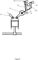
- FIG 3 is schematic representation of a typical prior art internal combustion engine and alternator system.
- An internal combustion engine is provided with a cylinder 10, a reciprocating piston 20 therein, an intake 30, an intake valve 40 (for controlling flow of gas into the engine through the intake 10), an exhaust 50, and an exhaust valve 60 (for regulating flow of exhaust gas out of the engine through the exhaust 50).
- Operation of the internal combustion engine causes the piston to reciprocate, thereby rotating a crankshaft 70.
- Rotation of the crankshaft 70 is used to drive a belt 80 which in turn operates alternator 90 via alternator pulley 100.
- the alternator pulley 100 is sized relative to the crankshaft 70 such that a higher rpm is provided at the alternator 90 that is present at the crankshaft 70. That is, the piston 20 must do work operating the alternator 90.
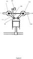
- FIG 4 is a schematic representation of a first embodiment of the present invention in which the prior art shown in figure 3 is modified in the following way.
- a turbine 110 is placed at the exhaust 50 such that exhaust gases from the engine rotate the turbine. Subsequently, such gases may leave the turbine via the exhaust outlet 120.
- the belt 80 is coupled to an axle of the turbine 110, rather than to the crankshaft 70, thereby reducing the load on the piston 20.
- the alternator 90 is driven by the belt 80, via the alternator pulley 100 as before.
- the turbine 110 is constructed to provide a rotational speed suitable for the alternator 90, such that gearing provided by selecting suitably sized pulleys for use with the belt 80 are not required.
- the alternator 90 could be connected directly to the axle of the turbine 110, foregoing the need for the belt 80 and alternator pulley 100.
- FIG 5 is a schematic representation of a second embodiment of the present invention, which is a further modification of the first embodiment shown in figure 4 .
- the belt 80 drives the alternator 90 and additionally a further accessory device 130, such as an air conditioning compressor unit.
- a further accessory device 140 is driven by a further belt 150, also on the axle of the turbine 110.
- the further accessory device 140 could be a water pump, for example; however, any other component that would more typically be driven directly by the crankshaft.
- FIG. 6 is a schematic representation of a third embodiment of the present invention, which is an alternative or additional modification of the first embodiment shown in figure 4 .
- the axle of the turbine 110 is made in common with an axle of a compressor 160 located at the intake, as is conventional in turbocharging devices.
- the alternator 90 is driven by the axle of the turbine 110.
- a metering valve 170 is located between the compressor 160 and the intake valve 40 and is configured to direct a gas flow from the compressor away from the intake valve 40, in the event that the compression provided by the compressor exceeds some threshold amount.
- the diverted gas 180 is conveyed to the exhaust outlet 120, or to other outlets such as the propelling nozzles discussed above.
- the metering valve 170 may divert all or none of the gas from the compressor 160, or any proportion therebetween.
- exhaust gas may be conveyed to the propelling nozzles of the present invention, it is preferable that exhaust gas is simply expelled in a conventional manner. Gas from another source may be provided to the nozzles.
- exhaust gas would be useful because it is both hot and at relatively high temperature; however, it may also contain relatively large amounts of unburned hydrocarbons and other impurities, which could cause the nozzles to block/clog over time, or at least reduce their efficiency. It is therefore desirable to use the heat and/or pressure of the exhaust gas to provide suitable air flow through the propelling nozzle(s) of the present invention.
- a heat exchanger could be used to reclaim waste heat, and/or a turbo expander could be used to extract pressure for re-use.
- the exhaust gas could then be passed to a silencer and/or exhaust pipe exit.
- FIG. 7 is a schematic representation of a fourth embodiment of the present invention, in which an air compressor 140 is driven by the turbine 110 to produce a stream of compressed air (or other gas) that flows down a pipe 300.
- the air compressor 140 may take air from ambient, or in alternative embodiments may take air from the engine inlet via metering valve 170.
- the compressor may be, for instance, a vane type compressor.
- This air compressed by the air compressor 140 may be supplied directly to the propelling nozzles and/or may be sent to a vortex tube 310 that splits the steam into a relatively high temperature stream that may be sent to a propelling nozzle via valve 320 and a relatively low temperature stream that may be sent to a propelling nozzle via valve 340.
- a heater and/or cooler 330 may be placed in-line with either the hot stream or the cold stream, or exceptionally to the compressed air stream prior to its introduction into the vortex tube 310.
- a further check valve 350 may also be included in the pipe 300.
- Each check valve shown in the drawings may optionally be accompanied or replaced by a pressure sensor.
- a controller may be configured to operate the or each check valve in response to pressure measured by the pressure sensor(s).
- a fuel control unit may be associated with the or each pressure sensor and/or check valve.
- FIG 8 is a schematic representation of a fifth embodiment of the present invention in which air flow from the metering valve 170 (compressed by the compressor 160) is supplied directly to the propelling nozzles via pipe 360 (conveying relatively cold air), and/or to a heat exchanger 380 via a check valve 370.
- the heat exchanger 380 may be configured to remove heat from the exhaust gases within the exhaust pipe 120 to warm the compressed air from the check valve 370 in order to provide a relatively high temperature stream 390 to a propelling nozzle, as described above.
- Figure 9 is a schematic representation of a sixth embodiment of the present invention in which compressed air is taken from the metering valve 170 as in figure 8 , but is conveyed to a vortex tube 310 as in figure 7 .
- a cooler 330 is provided in the pipe 300 prior to the vortex tube 310.
- FIG 10 is a schematic representation of an articulated lorry 180 incorporating an embodiment of the present invention.
- the lorry 180 when travelling forwards, suffers from drag, in particular form drag due to the substantially un-streamlined shape of the vehicle.
- Vortices 190 are formed in a low-pressure region behind the lorry 180, which contribute substantially to the form drag.
- the form drag could be reduces by streamlining the rear of the lorry 180; however, such an approach is undesirable because of the desire for the vehicle to allow easy access to its contents.
- First outlets 200 are provided on a periphery of the rear of the vehicle, and are specifically directed at the boundary of the vortex behind the vehicle.
- Second outlets 210 are provided on the rear of the vehicle spaced from the periphery, and are specifically directed into the low-pressure region behind the vehicle, in order to minimise drag by reducing vortices and thereby reducing resistance. These outlets are preferably nozzles of the form described above.
- the first outlets may be a convergent nozzles and/or a nozzles supplying relatively high temperature air
- the second outlets may be divergent nozzles and/or nozzles supplying relatively low temperature air.
- the figure shows two such outlets of each kind 200, 210; however, a single outlet, or multiple outlets (e.g. 3, 4, 5, 6, 10, 20, etc.) of each kind are also envisaged.
- the outlets may be located between the cabin of the articulated lorry 180 and the container body, or adjacent to any low pressure region and/or vortex produced by a similar moving vehicle, such as behind wheels.
- the outlets may be located on a spoiler, or adjacent to a spoiler.
- the outlets on / adjacent to a spoiler may be convergent nozzles and/or a nozzles supplying relatively high temperature air.
- An actuator and force amplifier assembly may be incorporated (e.g. adjacent to the spoiler), which may receive compressed air at a first pressure and convert it to a different pressure in accordance with Pascal's law.
- the nozzle arrangement may be reversed such that relatively high temperature air is expelled into a high pressure region in front of the vehicle, which may be present due to ram forces.
- the relatively high temperature air may warm the high pressure region, encouraging it to expand and dissipate, thereby reducing form drag.
- the nozzles may be directed toward relatively high pressure regions adjacent to the vehicle.
Landscapes
- Engineering & Computer Science (AREA)
- Mechanical Engineering (AREA)
- Chemical & Material Sciences (AREA)
- Combustion & Propulsion (AREA)
- Transportation (AREA)
- General Engineering & Computer Science (AREA)
- Fluid Mechanics (AREA)
- Physics & Mathematics (AREA)
- Supercharger (AREA)
- Jet Pumps And Other Pumps (AREA)
- Hydraulic Turbines (AREA)
- Exhaust Gas After Treatment (AREA)
- Steering-Linkage Mechanisms And Four-Wheel Steering (AREA)
- Apparatuses And Processes For Manufacturing Resistors (AREA)
Applications Claiming Priority (5)
| Application Number | Priority Date | Filing Date | Title |
|---|---|---|---|
| GB1503719.5A GB2536214B (en) | 2015-03-05 | 2015-03-05 | Engine system and method of generating electricity from an internal combustion engine |
| GB1506537.8A GB2536733B (en) | 2015-03-05 | 2015-04-17 | Method and system for reducing drag in a vehicle |
| EP20152068.1A EP3659902B1 (fr) | 2015-03-05 | 2016-03-02 | Procédé et système pour réduire la traînée dans un véhicule |
| EP16709511.6A EP3265366B1 (fr) | 2015-03-05 | 2016-03-02 | Procédé et système permettant de réduire la traînée d'un véhicule |
| PCT/GB2016/050549 WO2016139472A1 (fr) | 2015-03-05 | 2016-03-02 | Procédé et système permettant de réduire la traînée d'un véhicule |
Related Parent Applications (3)
| Application Number | Title | Priority Date | Filing Date |
|---|---|---|---|
| EP20152068.1A Division EP3659902B1 (fr) | 2015-03-05 | 2016-03-02 | Procédé et système pour réduire la traînée dans un véhicule |
| EP20152068.1A Division-Into EP3659902B1 (fr) | 2015-03-05 | 2016-03-02 | Procédé et système pour réduire la traînée dans un véhicule |
| EP16709511.6A Division EP3265366B1 (fr) | 2015-03-05 | 2016-03-02 | Procédé et système permettant de réduire la traînée d'un véhicule |
Publications (3)
| Publication Number | Publication Date |
|---|---|
| EP4086146A1 true EP4086146A1 (fr) | 2022-11-09 |
| EP4086146B1 EP4086146B1 (fr) | 2026-02-18 |
| EP4086146C0 EP4086146C0 (fr) | 2026-02-18 |
Family
ID=52998419
Family Applications (3)
| Application Number | Title | Priority Date | Filing Date |
|---|---|---|---|
| EP22182543.3A Active EP4086146B1 (fr) | 2015-03-05 | 2016-03-02 | Procédé et système pour réduire la traînée dans un véhicule |
| EP20152068.1A Active EP3659902B1 (fr) | 2015-03-05 | 2016-03-02 | Procédé et système pour réduire la traînée dans un véhicule |
| EP16709511.6A Active EP3265366B1 (fr) | 2015-03-05 | 2016-03-02 | Procédé et système permettant de réduire la traînée d'un véhicule |
Family Applications After (2)
| Application Number | Title | Priority Date | Filing Date |
|---|---|---|---|
| EP20152068.1A Active EP3659902B1 (fr) | 2015-03-05 | 2016-03-02 | Procédé et système pour réduire la traînée dans un véhicule |
| EP16709511.6A Active EP3265366B1 (fr) | 2015-03-05 | 2016-03-02 | Procédé et système permettant de réduire la traînée d'un véhicule |
Country Status (10)
| Country | Link |
|---|---|
| US (1) | US10414449B2 (fr) |
| EP (3) | EP4086146B1 (fr) |
| JP (3) | JP6929781B2 (fr) |
| KR (3) | KR20230109673A (fr) |
| CN (6) | CN111267974B (fr) |
| AU (6) | AU2016227483B2 (fr) |
| CA (6) | CA3181994C (fr) |
| ES (2) | ES2806431T3 (fr) |
| GB (6) | GB2536214B (fr) |
| WO (1) | WO2016139472A1 (fr) |
Families Citing this family (13)
| Publication number | Priority date | Publication date | Assignee | Title |
|---|---|---|---|---|
| US11603145B2 (en) * | 2016-09-05 | 2023-03-14 | OGAB Ltd. | Active drag-reduction system and a method of reducing drag experienced by a vehicle |
| CN108313144A (zh) * | 2017-01-17 | 2018-07-24 | 郑州宇通客车股份有限公司 | 降低车辆风阻的方法、车辆气路系统及车辆 |
| CA2989605A1 (fr) | 2017-02-27 | 2018-08-27 | Transtex Inc. | Appareil de reduction de la trainee d'air d'un vehicule et sa methode d'utilisation |
| CN107627835B (zh) * | 2017-09-07 | 2024-03-15 | 清华大学苏州汽车研究院(相城) | 一种降低汽车阻力的方法及尾气排放装置 |
| CN107933292A (zh) * | 2017-11-08 | 2018-04-20 | 清华大学苏州汽车研究院(相城) | 一种汽车发动机舱散热装置 |
| US10589802B2 (en) | 2017-12-20 | 2020-03-17 | Transtex Inc. | Automatically actuated rear air drag reducing system and method of use thereof |
| EP4079612B1 (fr) * | 2018-04-03 | 2023-11-29 | Magna Exteriors Inc. | Déflecteur actif avant - panneau plat |
| CN110871760B (zh) * | 2018-08-31 | 2024-12-27 | 宇通客车股份有限公司 | 一种客车及其后保险杠组件 |
| EP3857035B1 (fr) * | 2018-09-28 | 2025-12-31 | FB Design S.r.l. | Ensemble turbocompresseur amélioré |
| ES2875173B2 (es) | 2021-03-11 | 2023-06-15 | Univ Valencia Politecnica | Dispositivo y procedimiento de emulacion de sistemas de sobrealimentacion |
| GB2609488B (en) | 2021-08-05 | 2024-02-28 | Ogab Ltd | Gearbox temperature regulation system and method |
| GB2613193B (en) | 2021-11-26 | 2023-11-22 | Ogab Ltd | System and method of temperature regulation of a vehicle personnel compartment |
| PL448819A1 (pl) * | 2024-09-25 | 2026-03-30 | Krzysztof Dębicki | Turbina napędzana gazem spalinowym |
Citations (3)
| Publication number | Priority date | Publication date | Assignee | Title |
|---|---|---|---|---|
| US3910623A (en) * | 1972-01-03 | 1975-10-07 | Joseph E Mckeen | Means and methods for reducing oncoming air resistance and angle wind effects to a moving vehicle |
| WO1988009737A1 (fr) * | 1987-06-02 | 1988-12-15 | Ital Idee S.R.L. | Appareil d'aspiration de l'air se trouvant sur la couche limite de surfaces aerodynamiques, en particulier dans des voitures de course equipees d'un moteur a combustion interne |
| US20130140849A1 (en) * | 2011-12-01 | 2013-06-06 | Paccar Inc | Directed gas systems for improving aerodynamics of a vehicle in cross wind conditions |
Family Cites Families (76)
| Publication number | Priority date | Publication date | Assignee | Title |
|---|---|---|---|---|
| US2725944A (en) * | 1953-01-29 | 1955-12-06 | Ray G Lee | Stabilizer system for motor vehicles |
| US3972494A (en) * | 1974-08-30 | 1976-08-03 | Drews Hilbert F P | Vehicle air screen apparatus |
| FR2296295A1 (fr) * | 1974-12-23 | 1976-07-23 | Semt | Dispositif pour la production de puissance electrique a partir de l'energie recuperee sur les gaz d'echappement d'un moteur a combustion interne |
| US4006932A (en) * | 1975-07-21 | 1977-02-08 | The United States Of America As Represented By The Secretary Of The Department Of Transportation | Inflatable drag reducer for land vehicles |
| DE2935324A1 (de) * | 1979-08-31 | 1981-03-12 | Helfried Dipl.-Phys. 8021 Icking Crede | Kraftfahrzeug mit einem antrieb durch einen verbrennungsmotor und einer einrichtung zur verringerung des luftwiderstands. |
| GB2068851A (en) * | 1980-01-26 | 1981-08-19 | Bletsoe D | Drag-reducing arrangements for road vehicles |
| US4460055A (en) * | 1980-11-03 | 1984-07-17 | Karl Steiner | System to increase vehicle fuel efficiency |
| US4384630A (en) * | 1980-11-03 | 1983-05-24 | Karl Steiner | System to increase vehicle fuel efficiency |
| SU1096155A1 (ru) * | 1982-05-10 | 1984-06-07 | Казанский Ордена Трудового Красного Знамени И Ордена Дружбы Народов Авиационный Институт Им.А.Н.Туполева | Способ уменьшени аэродинамического сопротивлени транспортного средства |
| CH658884A5 (fr) * | 1984-10-01 | 1986-12-15 | Cerac Inst Sa | Groupe moteur a combustion interne. |
| JPH045695Y2 (fr) * | 1985-06-28 | 1992-02-18 | ||
| DE3838798A1 (de) * | 1988-11-17 | 1990-05-23 | Ingelheim Peter Graf Von | Injektor zur kombinierten nutzung |
| DE4000039A1 (de) * | 1990-01-03 | 1991-07-04 | Knut Villing | Windrad-/turbinenantrieb der lichtmaschine bei verbrennungsmotoren durch den abgasdruck im auspuffsystem |
| JPH0533662A (ja) * | 1991-07-31 | 1993-02-09 | Isuzu Ceramics Kenkyusho:Kk | 2ストロークターボコンパウンドエンジン |
| JPH0657784U (ja) * | 1992-02-10 | 1994-08-12 | 富田 陽子 | 走行するバス・トラック等の後端面に発生する圧力抗力を減少させる装置 |
| US5908217A (en) * | 1995-07-17 | 1999-06-01 | Georgia Tech Research Corporation | Pneumatic aerodynamic control and drag-reduction system for ground vehicles |
| DE19633205B4 (de) * | 1996-08-17 | 2010-05-12 | Dr. Ing. H.C. F. Porsche Aktiengesellschaft | Einrichtung zur Erzeugung von Antrieb an der Hinterachse eines Fahrzeuges |
| JP2000257510A (ja) | 1999-03-05 | 2000-09-19 | Tokyo Gas Co Ltd | 内燃機関 |
| US6470680B1 (en) * | 2000-03-15 | 2002-10-29 | Charl E Janeke | Manifold alternator generator |
| US6561575B2 (en) * | 2001-08-23 | 2003-05-13 | Vacuum Breaker Mile Maker | Air channeler for reducing wind resistance and method of use |
| CN100447385C (zh) * | 2002-05-21 | 2008-12-31 | 曼B与W狄赛尔公司 | 大型增压内燃发动机 |
| US7152393B2 (en) * | 2002-07-18 | 2006-12-26 | Daimlerchrysler Ag. | Arrangement for utilizing the throttle energy of an internal combustion engine |
| CN1530250A (zh) * | 2003-03-16 | 2004-09-22 | 骁 李 | 汽车尾部排气减阻方案 |
| US20050040637A1 (en) * | 2003-08-21 | 2005-02-24 | Wood Richard M. | Undercarriage flow control device and method for reducing the aerodynamic drag of ground vehicles |
| US6779834B1 (en) * | 2003-09-10 | 2004-08-24 | Russell D. Keller | Drag reduction channel apparatus for roadway vehicles |
| ITTO20031019A1 (it) * | 2003-12-18 | 2005-06-19 | Fiat Ricerche | Autoveicolo con dispositivo di controllo del flusso aerodinamico utilizzante getti sintetici. |
| US7152908B2 (en) * | 2004-07-01 | 2006-12-26 | Khosrow Shahbazi | Systems, methods, and media for reducing the aerodynamic drag of vehicles |
| US7364220B2 (en) * | 2004-07-01 | 2008-04-29 | Khosrow Shahbazi | Aerodynamic drag reduction systems |
| US20060046894A1 (en) * | 2004-08-09 | 2006-03-02 | Kyle Ronald L | Hybrid vehicle with exhaust powered turbo generator |
| EP1643094B1 (fr) * | 2004-10-01 | 2009-06-17 | J. Eberspächer GmbH & Co. KG | Système d'échappement d'un moteur à combustion interne et procédé correspondent pour le faire fonctionner |
| SE528351C2 (sv) * | 2005-01-27 | 2006-10-24 | Wm Data Caran Ab | Förbättringar av landfordons aerodynamiska egenskaper |
| ES2285889B1 (es) * | 2005-03-01 | 2008-10-16 | Joaquin Moscoso Gomez | Sistema para reducir el consumo de combustible en vehiculos. |
| US20090293474A1 (en) * | 2005-12-19 | 2009-12-03 | George Campbell Lucia | Turbine driven accessories |
| FR2902743B1 (fr) * | 2006-06-22 | 2009-05-22 | Plastic Omnium Cie | Systeme aerodynamique pour vehicule automobile |
| CN101191436A (zh) * | 2006-11-29 | 2008-06-04 | 上海通运汽车科技有限公司 | 一种汽车发动机排气涡轮发电装置 |
| CN101191432A (zh) * | 2006-11-29 | 2008-06-04 | 上海通运汽车科技有限公司 | 一种利用汽车发动机排气的空调辅助动力机构 |
| DE102007028143B4 (de) * | 2007-06-19 | 2012-10-18 | Thomas Fischer | Verfahren und Einrichtung zum Verstellen eines Funktionselementes in Abhängigkeit von der Strömungsgeschwindigkeit eines strömenden Mediums |
| CN201099288Y (zh) * | 2007-09-30 | 2008-08-13 | 陈世雄 | 可减低风阻的导流结构 |
| CN101652546B (zh) * | 2007-11-30 | 2011-09-07 | 阿尔法动力系统公司 | 与脉冲燃气涡轮机系统相结合的旋转式机械往复滑动金属叶片空气泵和边界层燃气轮机 |
| BRPI0821738A2 (pt) | 2007-12-21 | 2015-06-16 | Green Partners Technology Gmbh | Sistema de turbina a gás de ciclo aberto e fechado e semi-fechado de energia e de turbina de expansão e compressor de pistão de ciclo fechado, turbocompressor e métodos de produção de energia com turbina de gás de ciclo abreto, de compressão de gás de operação em turbocompressor e operação de sistema de motor |
| SE532164C2 (sv) * | 2008-03-17 | 2009-11-03 | Semcon Caran Ab | Förbättring av de aerodynamiska egenskaperna hos markfordon |
| EP2119581B1 (fr) * | 2008-05-06 | 2010-09-01 | C.R.F. Società Consortile per Azioni | Dispositif de distribution et de diffusion d'air avec jets synthétiques |
| FR2934556B1 (fr) * | 2008-08-04 | 2011-04-15 | Airbus France | Vehicule terrestre muni d'un systeme de propulsion par ecoulement d'air interne. |
| DK2151569T3 (da) * | 2008-08-06 | 2012-10-29 | Waertsilae Switzerland Ltd | Indretning til udtagelse af en udstødningsgas-delstrøm og forbrændingsmotor med denne indretning |
| DE102008047488A1 (de) * | 2008-09-17 | 2010-03-25 | Volkswagen Ag | Kraftfahrzeug |
| US20100089056A1 (en) * | 2008-10-09 | 2010-04-15 | General Electric Company | Integrated turbo-boosting and electric generation system and method |
| GB2457326B (en) * | 2008-10-17 | 2010-01-06 | Univ Loughborough | An exhaust arrangement for an internal combustion engine |
| DE102008060257A1 (de) * | 2008-12-03 | 2010-06-10 | Daimler Ag | Aktive Grenzschichtbeeinflussung zur Minimierung des Luftwiderstandes eines Kraftwagens |
| CN101746496A (zh) * | 2008-12-10 | 2010-06-23 | 朱晓义 | 动力驱动的运动装置 |
| CA2765735C (fr) * | 2009-06-23 | 2013-05-14 | Frank Visentin | Dispositif de reduction de trainee |
| US8371255B2 (en) * | 2009-06-30 | 2013-02-12 | Srdjan Perovic | Two stroke engine with regular lubrication system |
| CN201613953U (zh) * | 2009-10-13 | 2010-10-27 | 热流动力能源科技有限公司 | 滑移式车辆减低风阻的导流装置 |
| CN201520349U (zh) * | 2009-10-14 | 2010-07-07 | 热流动力能源科技有限公司 | 车辆用喷嘴型减阻结构 |
| CN102959185B (zh) * | 2010-09-24 | 2016-03-30 | 三菱重工业株式会社 | 涡轮发电机的控制方法及装置 |
| US8915082B2 (en) * | 2011-02-03 | 2014-12-23 | Ford Global Technologies, Llc | Regenerative assisted turbocharger system |
| CN102865274A (zh) * | 2011-07-09 | 2013-01-09 | 拉姆金动力系统有限责任公司 | 涡流发生器 |
| US8671671B1 (en) * | 2011-07-14 | 2014-03-18 | Northern California Diagnostic Laboratories | Exhaust system for an internal combustion engine |
| DE102011053500B4 (de) | 2011-09-12 | 2022-02-03 | Dr. Ing. H.C. F. Porsche Aktiengesellschaft | Kühleinrichtung für ein Kraftfahrzeug mit einem ausfahrbarem Heckspoiler und einem Ladeluftkühler |
| US8770649B2 (en) * | 2011-10-29 | 2014-07-08 | Alexander Praskovsky | Device, assembly, and system for reducing aerodynamic drag |
| US8950534B2 (en) * | 2011-12-01 | 2015-02-10 | Paccar Inc | Directed air systems for improving aerodynamics of a vehicle |
| JP2013124558A (ja) | 2011-12-13 | 2013-06-24 | Nippon Soken Inc | 過給機付き内燃機関の制御装置 |
| JP6031663B2 (ja) * | 2012-09-07 | 2016-11-24 | 上野 康男 | 自動車用空気抵抗低減装置 |
| AT513886B1 (de) * | 2013-01-22 | 2014-11-15 | Avl List Gmbh | Fahrzeug, insbesondere Rennfahrzeug |
| GB201307610D0 (en) * | 2013-04-26 | 2013-06-12 | Controlled Power Technologies Ltd | Exhaust Driven Turbine-Generator Integrated Gas Energy Recovery System |
| JP2014234808A (ja) | 2013-06-05 | 2014-12-15 | 日産自動車株式会社 | 過給機付内燃機関の排気還流装置および排気還流方法 |
| JP6191354B2 (ja) * | 2013-09-18 | 2017-09-06 | スズキ株式会社 | 車体下部のカバー構造 |
| CN104129443B (zh) * | 2014-07-29 | 2021-06-22 | 朱晓义 | 节能汽车 |
| DE102014018990A1 (de) * | 2014-12-18 | 2016-06-23 | GM Global Technology Operations LLC (n. d. Ges. d. Staates Delaware) | Kraftfahrzeug mit belüftetem Radkasten |
| US9527534B2 (en) * | 2015-01-22 | 2016-12-27 | John Knobloch | Systems and methods for reducing aerodynamic drag on cargo trucks |
| GB201505104D0 (en) * | 2015-03-26 | 2015-05-06 | Fleming James G | A drag reduction system for vehicles |
| DE102015205737A1 (de) * | 2015-03-30 | 2016-10-06 | Avl List Gmbh | Brennkraftmaschine mit Abgasenergienutzung und Verfahren zum Betrieb einer solchen Brennkraftmaschine |
| US20160039477A1 (en) * | 2015-08-24 | 2016-02-11 | Othman Bin Ahmad | Zero aerodynamic drag vehicles |
| CN106481414B (zh) * | 2015-08-26 | 2020-12-04 | 福特环球技术公司 | 带有低压egr装置的机械增压内燃发动机及其操作方法 |
| US11142264B2 (en) * | 2015-11-20 | 2021-10-12 | David Connors | Draft turbulence reduction system and method |
| DE102017103881A1 (de) * | 2017-02-24 | 2018-08-30 | Dr. Ing. H.C. F. Porsche Aktiengesellschaft | Kraftfahrzeug mit frontseitigem Diffusor |
| DE102019006670A1 (de) * | 2019-09-23 | 2020-03-26 | Daimler Ag | Kraftfahrzeug, umfassend eine Verbrennungskraftmaschine, eine Steuereinheit und eine damit verbundene Sensorik |
-
2015
- 2015-03-05 GB GB1503719.5A patent/GB2536214B/en active Active
- 2015-04-17 GB GB1703623.7A patent/GB2549838B/en not_active Expired - Fee Related
- 2015-04-17 GB GB1809442.5A patent/GB2564948B/en not_active Expired - Fee Related
- 2015-04-17 GB GB1506537.8A patent/GB2536733B/en not_active Expired - Fee Related
- 2015-04-17 GB GB1716638.0A patent/GB2557428B/en not_active Expired - Fee Related
- 2015-04-17 GB GB1802855.5A patent/GB2560635B/en active Active
-
2016
- 2016-03-02 ES ES16709511T patent/ES2806431T3/es active Active
- 2016-03-02 CN CN202010100332.2A patent/CN111267974B/zh active Active
- 2016-03-02 CN CN202010100331.8A patent/CN111267973B/zh not_active Expired - Fee Related
- 2016-03-02 EP EP22182543.3A patent/EP4086146B1/fr active Active
- 2016-03-02 CN CN202010100071.4A patent/CN111267971B/zh not_active Expired - Fee Related
- 2016-03-02 WO PCT/GB2016/050549 patent/WO2016139472A1/fr not_active Ceased
- 2016-03-02 CA CA3181994A patent/CA3181994C/fr active Active
- 2016-03-02 KR KR1020237019981A patent/KR20230109673A/ko active Pending
- 2016-03-02 JP JP2017542906A patent/JP6929781B2/ja not_active Expired - Fee Related
- 2016-03-02 EP EP20152068.1A patent/EP3659902B1/fr active Active
- 2016-03-02 CN CN202010100050.2A patent/CN111267970B/zh not_active Expired - Fee Related
- 2016-03-02 CA CA3181977A patent/CA3181977C/fr active Active
- 2016-03-02 CN CN201680013225.8A patent/CN107428381B/zh not_active Expired - Fee Related
- 2016-03-02 CA CA3181999A patent/CA3181999C/fr active Active
- 2016-03-02 CA CA3182414A patent/CA3182414A1/fr active Pending
- 2016-03-02 EP EP16709511.6A patent/EP3265366B1/fr active Active
- 2016-03-02 KR KR1020237019979A patent/KR102734962B1/ko active Active
- 2016-03-02 US US15/555,072 patent/US10414449B2/en active Active
- 2016-03-02 ES ES20152068T patent/ES2931099T3/es active Active
- 2016-03-02 AU AU2016227483A patent/AU2016227483B2/en not_active Ceased
- 2016-03-02 CN CN202010100330.3A patent/CN111267972B/zh not_active Expired - Fee Related
- 2016-03-02 KR KR1020177027193A patent/KR20170127478A/ko not_active Abandoned
- 2016-03-02 CA CA3181988A patent/CA3181988A1/fr active Pending
- 2016-03-02 CA CA2976039A patent/CA2976039C/fr active Active
-
2020
- 2020-03-30 AU AU2020202262A patent/AU2020202262B2/en not_active Ceased
- 2020-03-30 AU AU2020202263A patent/AU2020202263B2/en not_active Ceased
- 2020-03-30 AU AU2020202261A patent/AU2020202261B2/en not_active Ceased
- 2020-03-30 AU AU2020202264A patent/AU2020202264B2/en active Active
-
2021
- 2021-08-04 AU AU2021212034A patent/AU2021212034B2/en not_active Ceased
- 2021-08-10 JP JP2021130992A patent/JP7270004B2/ja active Active
-
2023
- 2023-04-21 JP JP2023069704A patent/JP7584817B2/ja active Active
Patent Citations (3)
| Publication number | Priority date | Publication date | Assignee | Title |
|---|---|---|---|---|
| US3910623A (en) * | 1972-01-03 | 1975-10-07 | Joseph E Mckeen | Means and methods for reducing oncoming air resistance and angle wind effects to a moving vehicle |
| WO1988009737A1 (fr) * | 1987-06-02 | 1988-12-15 | Ital Idee S.R.L. | Appareil d'aspiration de l'air se trouvant sur la couche limite de surfaces aerodynamiques, en particulier dans des voitures de course equipees d'un moteur a combustion interne |
| US20130140849A1 (en) * | 2011-12-01 | 2013-06-06 | Paccar Inc | Directed gas systems for improving aerodynamics of a vehicle in cross wind conditions |
Non-Patent Citations (1)
| Title |
|---|
| SRISHA M.V. RAOAG. JAGADEESH: "Novel supersonic nozzles for mixing enhancement in supersonic ejectors", APPLIED THERMAL ENGINEERING, vol. 71, 5 October 2014 (2014-10-05), pages 62 - 71, XP029090223, DOI: 10.1016/j.applthermaleng.2014.06.025 |
Also Published As
Similar Documents
| Publication | Publication Date | Title |
|---|---|---|
| AU2021212034B2 (en) | Method and system for reducing drag in a vehicle | |
| US20230192203A1 (en) | Active drag-reduction system and a method of reducing drag experienced by a vehicle |
Legal Events
| Date | Code | Title | Description |
|---|---|---|---|
| PUAI | Public reference made under article 153(3) epc to a published international application that has entered the european phase |
Free format text: ORIGINAL CODE: 0009012 |
|
| STAA | Information on the status of an ep patent application or granted ep patent |
Free format text: STATUS: REQUEST FOR EXAMINATION WAS MADE |
|
| 17P | Request for examination filed |
Effective date: 20220701 |
|
| AC | Divisional application: reference to earlier application |
Ref document number: 3265366 Country of ref document: EP Kind code of ref document: P Ref document number: 3659902 Country of ref document: EP Kind code of ref document: P |
|
| AK | Designated contracting states |
Kind code of ref document: A1 Designated state(s): AL AT BE BG CH CY CZ DE DK EE ES FI FR GB GR HR HU IE IS IT LI LT LU LV MC MK MT NL NO PL PT RO RS SE SI SK SM TR |
|
| STAA | Information on the status of an ep patent application or granted ep patent |
Free format text: STATUS: EXAMINATION IS IN PROGRESS |
|
| 17Q | First examination report despatched |
Effective date: 20250217 |
|
| GRAP | Despatch of communication of intention to grant a patent |
Free format text: ORIGINAL CODE: EPIDOSNIGR1 |
|
| STAA | Information on the status of an ep patent application or granted ep patent |
Free format text: STATUS: GRANT OF PATENT IS INTENDED |
|
| INTG | Intention to grant announced |
Effective date: 20251006 |
|
| GRAS | Grant fee paid |
Free format text: ORIGINAL CODE: EPIDOSNIGR3 |
|
| GRAA | (expected) grant |
Free format text: ORIGINAL CODE: 0009210 |
|
| STAA | Information on the status of an ep patent application or granted ep patent |
Free format text: STATUS: THE PATENT HAS BEEN GRANTED |
|
| AC | Divisional application: reference to earlier application |
Ref document number: 3659902 Country of ref document: EP Kind code of ref document: P Ref document number: 3265366 Country of ref document: EP Kind code of ref document: P |
|
| AK | Designated contracting states |
Kind code of ref document: B1 Designated state(s): AL AT BE BG CH CY CZ DE DK EE ES FI FR GB GR HR HU IE IS IT LI LT LU LV MC MK MT NL NO PL PT RO RS SE SI SK SM TR |
|
| REG | Reference to a national code |
Ref country code: CH Ref legal event code: F10 Free format text: ST27 STATUS EVENT CODE: U-0-0-F10-F00 (AS PROVIDED BY THE NATIONAL OFFICE) Effective date: 20260218 Ref country code: GB Ref legal event code: FG4D |
|
| REG | Reference to a national code |
Ref country code: IE Ref legal event code: FG4D |
|
| REG | Reference to a national code |
Ref country code: DE Ref legal event code: R096 Ref document number: 602016094791 Country of ref document: DE |
|
| PGFP | Annual fee paid to national office [announced via postgrant information from national office to epo] |
Ref country code: GB Payment date: 20260320 Year of fee payment: 11 |
|
| PGFP | Annual fee paid to national office [announced via postgrant information from national office to epo] |
Ref country code: IE Payment date: 20260320 Year of fee payment: 11 |
|
| U01 | Request for unitary effect filed |
Effective date: 20260316 |