EP4086170A1 - Luftfahrzeug - Google Patents
Luftfahrzeug Download PDFInfo
- Publication number
- EP4086170A1 EP4086170A1 EP20910289.6A EP20910289A EP4086170A1 EP 4086170 A1 EP4086170 A1 EP 4086170A1 EP 20910289 A EP20910289 A EP 20910289A EP 4086170 A1 EP4086170 A1 EP 4086170A1
- Authority
- EP
- European Patent Office
- Prior art keywords
- aircraft
- frame
- hovering
- during
- mounting part
- Prior art date
- Legal status (The legal status is an assumption and is not a legal conclusion. Google has not performed a legal analysis and makes no representation as to the accuracy of the status listed.)
- Pending
Links
Images


Classifications
-
- B—PERFORMING OPERATIONS; TRANSPORTING
- B64—AIRCRAFT; AVIATION; COSMONAUTICS
- B64C—AEROPLANES; HELICOPTERS
- B64C27/00—Rotorcraft; Rotors peculiar thereto
- B64C27/52—Tilting of rotor bodily relative to fuselage
-
- B—PERFORMING OPERATIONS; TRANSPORTING
- B64—AIRCRAFT; AVIATION; COSMONAUTICS
- B64C—AEROPLANES; HELICOPTERS
- B64C29/00—Aircraft capable of landing or taking-off vertically, e.g. vertical take-off and landing [VTOL] aircraft
- B64C29/0008—Aircraft capable of landing or taking-off vertically, e.g. vertical take-off and landing [VTOL] aircraft having its flight directional axis horizontal when grounded
-
- B—PERFORMING OPERATIONS; TRANSPORTING
- B64—AIRCRAFT; AVIATION; COSMONAUTICS
- B64D—EQUIPMENT FOR FITTING IN OR TO AIRCRAFT; FLIGHT SUITS; PARACHUTES; ARRANGEMENT OR MOUNTING OF POWER PLANTS OR PROPULSION TRANSMISSIONS IN AIRCRAFT
- B64D1/00—Dropping, ejecting, releasing or receiving articles, liquids, or the like, in flight
- B64D1/22—Taking-up articles from earth's surface
-
- B—PERFORMING OPERATIONS; TRANSPORTING
- B64—AIRCRAFT; AVIATION; COSMONAUTICS
- B64D—EQUIPMENT FOR FITTING IN OR TO AIRCRAFT; FLIGHT SUITS; PARACHUTES; ARRANGEMENT OR MOUNTING OF POWER PLANTS OR PROPULSION TRANSMISSIONS IN AIRCRAFT
- B64D9/00—Equipment for handling freight; Equipment for facilitating passenger embarkation or the like
-
- B—PERFORMING OPERATIONS; TRANSPORTING
- B64—AIRCRAFT; AVIATION; COSMONAUTICS
- B64U—UNMANNED AERIAL VEHICLES [UAV]; EQUIPMENT THEREFOR
- B64U10/00—Type of UAV
- B64U10/10—Rotorcrafts
- B64U10/13—Flying platforms
- B64U10/16—Flying platforms with five or more distinct rotor axes, e.g. octocopters
-
- B—PERFORMING OPERATIONS; TRANSPORTING
- B64—AIRCRAFT; AVIATION; COSMONAUTICS
- B64U—UNMANNED AERIAL VEHICLES [UAV]; EQUIPMENT THEREFOR
- B64U30/00—Means for producing lift; Empennages; Arrangements thereof
- B64U30/10—Wings
-
- B—PERFORMING OPERATIONS; TRANSPORTING
- B64—AIRCRAFT; AVIATION; COSMONAUTICS
- B64U—UNMANNED AERIAL VEHICLES [UAV]; EQUIPMENT THEREFOR
- B64U30/00—Means for producing lift; Empennages; Arrangements thereof
- B64U30/20—Rotors; Rotor supports
-
- B—PERFORMING OPERATIONS; TRANSPORTING
- B64—AIRCRAFT; AVIATION; COSMONAUTICS
- B64U—UNMANNED AERIAL VEHICLES [UAV]; EQUIPMENT THEREFOR
- B64U50/00—Propulsion; Power supply
- B64U50/10—Propulsion
- B64U50/19—Propulsion using electrically powered motors
-
- G—PHYSICS
- G05—CONTROLLING; REGULATING
- G05D—SYSTEMS FOR CONTROLLING OR REGULATING NON-ELECTRIC VARIABLES
- G05D1/00—Control of position, course, altitude or attitude of land, water, air or space vehicles, e.g. using automatic pilots
- G05D1/08—Control of attitude, i.e. control of roll, pitch, or yaw
- G05D1/0808—Control of attitude, i.e. control of roll, pitch, or yaw specially adapted for aircraft
- G05D1/0858—Control of attitude, i.e. control of roll, pitch, or yaw specially adapted for aircraft specially adapted for vertical take-off of aircraft
Definitions
- the present disclosure relates to an aircraft.
- Drones or unmanned aerial vehicles UAVs
- UAVs Unmanned Aerial Unmanned Aerial Vehicles
- flying vehicles other flying vehicles
- a multicopter type with multiple rotor blades is one example (see, for example, Patent Literature 1).
- one objective of the present disclosure is to provide an aircraft that can efficiently improve speed performance and fuel consumption.
- the aircraft according to the present disclosure is an aircraft that is capable of forward flight and hovering, comprising:
- an aircraft that can efficiently improve speed performance and fuel consumption can be provided.
- the invention according to the present embodiment has the following configuration.
- An aircraft capable of forward flight and hovering comprising:
- the loading part has a connection part that is rotatable in at least a forward and backward direction with respect to the frame.
- connection part has an attitude control mechanism that controls the attitude of the loading part.
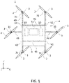
- FIG. 1 is a plan view of an aircraft 1 according to one embodiment.
- FIG. 2 is a front view of the aircraft 1 according to the embodiment.
- FIG. 3 is a side view of the airframe 1 according to the embodiment.
- the aircraft 1 is, for example, an aircraft that is capable of flying or hovering in a forward direction.
- the aircraft 1 has, for example, a rotary blade 2 (lift generating part), a motor 3 for rotating the rotary blade 2, and a frame 4 that holds the rotary blade 2 and to which the motor 4 to which the motor 3 is attached.
- the front-back direction of the aircraft 1 is the Y-axis direction
- the left-right (or horizontal) direction is the X-axis direction
- the up-down (or vertical) direction is the Z-axis direction.
- the aircraft 1 uses the +Y direction as the forward direction.
- the rotor blade 2 rotates under the output from the motor 3.
- the rotation of the rotor blade 2 generates propulsive force to the aircraft 1.
- the rotor blade 2 is an example of a lift generating part.
- each of the multiple rotor blades can be controlled to rotate clockwise or counterclockwise or to stop, thereby enabling vertical and horizontal movement of the aircraft 1, as well as turning and yaw axis rotation.
- the number of blades (rotors) of the present disclosure may be an arbitrary number (e.g., 1, 2, 3, 4, or more blades).
- the shape of the blade may be any shape such as a flat shape, a curved shape, a twisted shape, a tapered shape, or a combination thereof. Further, the shape of the blade can be changed (for example, stretching, folding, bending, etc.).
- the blades may be symmetric or asymmetric (having different shaped upper and lower surfaces). Symmetrical means that the upper and lower surface profiles are symmetrical with respect to the blade string lines of the blades. Asymmetrical means not symmetrical as above.
- the blades can be formed to have a geometric shape suitable for generating dynamic aerodynamic forces (e.g., lift, thrust) when an air foil, a wing, or a blade moves in the air.
- the geometric shape of the blade can be appropriately selected to optimize the dynamic air characteristics of the blade, such as increasing lift and thrust and reducing drag.
- the rotor blade 2 may be a propulsion type (push type), a traction type (pull type), or a combination thereof.
- the motor 3 causes the rotation of the propeller 2, and for example, the drive unit can include an electric motor, an engine, or the like.
- the blades can be driven by the motor and rotate around the axis of rotation of the motor (e.g., the major axis of the motor) in a clockwise and/or counterclockwise direction.
- the propeller (rotor blade 2) comprising the blade has a drive shaft in which an output is transmitted from the power shaft of the motor via a pulley or the like, and the blade may rotate around the drive shaft.
- each blade can be controlled independently. For example, in a multicopter type aircraft, some of the blades rotate in one direction and the other blades rotate in the other direction. The blades can all rotate at the same rotation speed, or can rotate at different rotation speeds.
- the rotation speed can be automatically or manually determined based on the dimensions (eg, size, weight) or control state (speed, moving direction, etc.) of the moving body.
- the frame 4 is a member that supports the corresponding motor 3 and propeller 2, respectively.
- the frame 4 may be provided with a color-displaying body such as an LED to indicate the flight state, flight direction, and the like of the rotary wing aircraft.
- the frame 4 according to the present embodiment can be formed of a material appropriately selected from carbon, carbon fiber resin, glass fiber resin, stainless steel, aluminum, magnesium, or the like, or an alloy or combination thereof.
- Frame 4 as shown in FIGS. 1 and 2 , is comprised of a first frame 40 and a second frame 41.
- the second frames 41, 41 are provided side-by-side between the first frames 40 and 40, which are provided side by side substantially in parallel.
- the first frame 40 and the second frame 41 are connected by known methods, such as, for example, joints and caulking.
- the first frames 40 and 40 are longitudinally oriented in the Y direction and are aligned at predetermined intervals along the X direction.
- Rotating blades 2 are attached to both ends of the first frames 40, 40 via a motor 3.
- the second frames 41, 41 are aligned at predetermined intervals along the y-direction with the x-direction as the longitudinal direction.
- the frame 4 includes a third frame 42 which extends in the X direction from the first frame 40 starting from between the vertices V1 and V2 on the first frame 40; and a fourth frame 43 which extends in the X direction from the first frame 40 as opposed to the third frame 42 starting from between the vertices V3 and V4 on the first frame 40.
- the rotor blade 2 is attached via the motor 3.
- the rotor blade 2 is attached via the motor 3.
- each end of the frame 4 is provided with a motor mount 31 that supports the rotor blade 2 and motor 3.
- Motor mount 31 is an example of a support part.
- the motor mount 31 is provided so that the rotation axis RA of the rotor blade 2 is tilted in front of the aircraft 1 and with respect to the frame 4.
- the motor mount 3 may have a tapered shape that tapers from the end of the frame 4 toward the longitudinal direction of the frame 4.
- the motor mount 31 according to the present embodiment is fixed at the end of the frame 4. That is, the motor mount 31 immobilizes the rotary blade 2 with respect to the frame 4. That is, the rotor blade 2 itself does not move rotationally with respect to the frame 4.
- the mounting part 5 is, for example, a mechanism for mounting and holding a load (loadable object) 51.
- the battery 50 may be loaded on the mounting part 5.
- the mounting part 5 is provided on the frame 4 and stores the load 51.
- the batteries 50 are arranged side by side in the X direction with the luggage 51 in between.
- the number of batteries 50 to be loaded is not particularly limited.
- the mounting part 5 may have not only a square portion having V1 to V4 as a vertex but also a square portion protruding in the -Y direction from this square portion in a plan view.,
- the mounting part 5 may be fixed to the frame 4 so as not to move rotationally. Further, the mounting part 5 may have a mechanism that can rotate with respect to the frame 4.
- the mounting part 5 has a hinge (connecting part) 52 for connecting the housing of the mounting part 5 and the frame 4.
- the hinge 52 as a fulcrum, the mounting part 5 is configured to be rotatable in the pitch direction with respect to the frame 4.
- the limit of the angle at which the mounting part 5 rotates with respect to the frame 4 via the hinge 52 is not particularly limited.
- the orientation of the mounting part 5 can be kept horizontal so that the load 51 does not tilt.
- the load 51 can be held in a stable state even during flight and delivered to the destination.
- the hinge 52 according to the present embodiment rotates the mounting part 5 only in the front-rear direction (that is, the pitch direction), which is the same direction as the traveling direction.
- the mounting part 5 may be further rotated in the left-right direction (roll direction and / or yaw direction).
- the hinge 52 may have a mechanism such as a gimbal that actively controls the posture of the mounting part 5 by a motor or the like. This makes it possible to control the attitude of the mounting part 5 during flight. Then, the wobbling (natural vibration, etc.) of the mounting part 5 is further reduced, and the load 51 can be delivered more stably.
- the hinge 52 may be configured to be connected to the luggage 51 instead of the mounting part 5.
- the shape and / or mechanism of the mounting part 5 is not particularly limited as long as the load 51 can be stored and held. Further, the mechanism for holding the position and inclination of the load 51 mounted on the mounting part 5 may be, for example, a tilt mechanism for tilting the load 51. Further, as described above, the mounting part 5 does not necessarily have to have a structure that can move rotationally with respect to the frame 4.
- the aircraft 1 in the present embodiment does not have a landing gear in order to reduce the weight. Therefore, in the present embodiment, when the aircraft 1 lands, the mounting part 5 exerts the function of the landing gear.
- landing gears may be appropriately provided on the frame 4, the mounting part 5, and the like.
- FIG. 5 is a side view showing a flight state of the aircraft 1 when hovering according to the present embodiment.
- FIG. 3 is also a side view showing the flight state of the aircraft 1 during level flight according to the present embodiment.
- the aircraft 1 when the aircraft 1 is hovering, the aircraft 1 takes a backward leaning posture so that the lift obtained by the rotor blade 2 is upward.
- the frame 4 becomes horizontal, and the rotation axis RA of the rotor blade 2 faces in the Y-axis direction and diagonally upward.
- the lift obtained from the rotor 2 is composed of a forward component and an upward component.
- the aircraft 1 can move in the horizontal direction while keeping the attitude of the mounting part 5 horizontal in the air.
- FIGS. 6 and 7 are diagrams for comparing the front projected area of the aircraft during forward flight and the front projected area of the aircraft during hovering.
- the front projected area means the area of the projected area of the frame 4 and the mounting part 5 when the aircraft 1 is viewed from the front in the horizontal direction (that is, when viewed in the Y-axis direction).
- the front projected area is obtained by imaging the front surface of the aircraft 1 during horizontal flight and hovering from the horizontal direction, and calculating the area occupied by the frame 4 and the mounting part 5 in the captured image based on the actual size of the aircraft 1.
- the area surrounded by the thick broken line in FIG. 6 indicates the projected area S1 of the airframe during forward flight.
- the area surrounded by the thick broken line in FIG. 7 indicates the projection area S2 of the airframe during hovering.
- the frame 4 and the mounting part 5 occupy most of the components of the aircraft 1, and are a major factor in air resistance during flight.
- the projection area S1 during forward flight is narrower than the projection area S2 during hovering. That is, in the aircraft 1 in the present embodiment, the front projected area during forward flight is smaller than the front projected area during hovering.
- the aircraft 1 according to the present embodiment has a smaller projection area from the front when hovering. Then, the air resistance received from the front of the aircraft 1 is reduced. That is, the configuration of the aircraft 1 according to the present embodiment can efficiently improve the speed performance and fuel efficiency during forward flight.
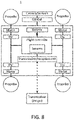
- a flight controller is a so-called processing unit.
- the processing unit may have one or more processors, such as a programmable processor (e.g., a central processing unit (CPU)).
- the processing unit has a memory (not shown) and it is possible to access the memory.
- the memory stores logic, codes, and / or program instructions that can be executed by the flight controller to perform one or more steps.
- the memory may include, for example, a separable medium such as an SD card or random access memory (RAM) or an external storage device. Data obtained from cameras and sensors may be transmitted directly to the memory and stored. For example, still image ⁇ dynamic image data taken by a camera or the like is recorded in a built-in memory or an external memory.
- the processing unit includes a control module configured to control the state of the aircraft.
- the control module may control a propulsion mechanism (motor and the like) in order to adjust the spatial arrangement, velocity, and/or acceleration of the aircraft having six degrees of freedom (translational motions x, y, and z, and rotational motions ⁇ x, ⁇ y, and ⁇ z).
- the control module can control one or more of the states of a mounted part and sensors.
- the processing unit can communicate with a transmission/reception unit configured to send and/or receive data from one or more external devices (e.g., a terminal, display device, or other remote controller).
- the transmission/reception unit can use any suitable communication means such as wired or wireless communication.
- the transmission/reception unit can use one or more of a local area network (LAN), a wide area network (WAN), infrared, wireless, WiFi, point-to-point (P2P) network, telecommunication network, cloud communication, and the like.
- the transmission/reception unit can transmit and/or receive one or more of, data acquired by sensors, process results generated by the processing unit, predetermined control data, user command from a terminal or a remote controller, and the like.
- Sensors according to the present embodiment may include inertial sensors (acceleration sensors, gyro sensors), GPS sensors, proximity sensors (e.g., LiDAR), or vision/image sensors (e.g., cameras).
- inertial sensors acceleration sensors, gyro sensors
- GPS sensors GPS sensors
- proximity sensors e.g., LiDAR
- vision/image sensors e.g., cameras
- the aircraft of the present disclosure can be expected to be used as an aircraft for delivery services, and to be used as an industrial aircraft in a warehouse or a factory.
- the aircraft of the present disclosure can be used in airplane-related industries such as multicopters and drones.
- the present disclosure can be suitably used as an aerial vehicle equipped with a camera or the like.
- this technology can be used in various industries such as security field, agriculture, and infrastructure monitoring.
Landscapes
- Engineering & Computer Science (AREA)
- Aviation & Aerospace Engineering (AREA)
- Mechanical Engineering (AREA)
- Chemical & Material Sciences (AREA)
- Combustion & Propulsion (AREA)
- Remote Sensing (AREA)
- Radar, Positioning & Navigation (AREA)
- Physics & Mathematics (AREA)
- General Physics & Mathematics (AREA)
- Automation & Control Theory (AREA)
- Toys (AREA)
Applications Claiming Priority (1)
| Application Number | Priority Date | Filing Date | Title |
|---|---|---|---|
| PCT/JP2020/000001 WO2021137271A1 (ja) | 2020-01-01 | 2020-01-01 | 飛行体 |
Publications (2)
| Publication Number | Publication Date |
|---|---|
| EP4086170A1 true EP4086170A1 (de) | 2022-11-09 |
| EP4086170A4 EP4086170A4 (de) | 2023-09-27 |
Family
ID=76559028
Family Applications (1)
| Application Number | Title | Priority Date | Filing Date |
|---|---|---|---|
| EP20910289.6A Pending EP4086170A4 (de) | 2020-01-01 | 2020-01-01 | Luftfahrzeug |
Country Status (5)
| Country | Link |
|---|---|
| US (1) | US20230033507A1 (de) |
| EP (1) | EP4086170A4 (de) |
| JP (4) | JP7137257B2 (de) |
| CN (2) | CN214325365U (de) |
| WO (1) | WO2021137271A1 (de) |
Families Citing this family (6)
| Publication number | Priority date | Publication date | Assignee | Title |
|---|---|---|---|---|
| GB201802611D0 (en) * | 2018-02-17 | 2018-04-04 | Panelplane Ltd | Teleporter |
| US20230033507A1 (en) * | 2020-01-01 | 2023-02-02 | Aeronext Inc. | Aircraft |
| JP6952380B1 (ja) * | 2020-08-11 | 2021-10-20 | 株式会社エアロネクスト | 移動体 |
| EP4393819A4 (de) * | 2021-08-23 | 2025-07-30 | Aeronext Inc | Flugobjekt |
| JP2023086311A (ja) * | 2021-12-10 | 2023-06-22 | 株式会社エクセディ | ドローン用モータ |
| EP4711283A1 (de) * | 2024-09-13 | 2026-03-18 | Fuvex Civil, SL | Unbemanntes luftfahrzeug zur inspektion einer linieninfrastruktur |
Family Cites Families (14)
| Publication number | Priority date | Publication date | Assignee | Title |
|---|---|---|---|---|
| US6824095B2 (en) * | 2001-11-29 | 2004-11-30 | Youbin Mao | VSTOL vehicle |
| US8733690B2 (en) | 2009-08-24 | 2014-05-27 | Joby Aviation, Inc. | Lightweight vertical take-off and landing aircraft and flight control paradigm using thrust differentials |
| US20140061376A1 (en) * | 2010-05-26 | 2014-03-06 | Aerovironment Inc | Reconfigurable battery-operated vehicle system |
| EP2576342A4 (de) * | 2010-05-26 | 2014-08-20 | Aerovironment Inc | Rekonfigurierbares batteriebetriebenes fahrzeugsystem |
| JP5812849B2 (ja) | 2011-12-21 | 2015-11-17 | 株式会社Ihiエアロスペース | 小型無人機 |
| CN106043679B (zh) * | 2016-07-28 | 2018-09-07 | 易瓦特科技股份公司 | 多轴动力源无人飞行设备 |
| WO2018066043A1 (ja) * | 2016-10-03 | 2018-04-12 | 株式会社Aeronext | 配達用回転翼機 |
| EP3366582B1 (de) | 2017-02-28 | 2019-07-24 | AIRBUS HELICOPTERS DEUTSCHLAND GmbH | Multirotorflugzeug mit einem flugwerk und einer anordnung mit schuberzeugungseinheiten |
| JP2019026233A (ja) * | 2017-07-27 | 2019-02-21 | 株式会社Mmラボ | 無人航空機 |
| JP6707761B2 (ja) * | 2017-09-27 | 2020-06-10 | 株式会社石川エナジーリサーチ | エンジン搭載自立型飛行装置 |
| JP2018203226A (ja) * | 2018-03-13 | 2018-12-27 | 株式会社エアロネクスト | 飛行体 |
| JP3217820U (ja) | 2018-04-27 | 2018-09-06 | 東光鉄工株式会社 | ドローン |
| JP6606648B1 (ja) * | 2018-07-17 | 2019-11-20 | 株式会社プロドローン | 無人航空機 |
| US20230033507A1 (en) * | 2020-01-01 | 2023-02-02 | Aeronext Inc. | Aircraft |
-
2020
- 2020-01-01 US US17/790,707 patent/US20230033507A1/en not_active Abandoned
- 2020-01-01 WO PCT/JP2020/000001 patent/WO2021137271A1/ja not_active Ceased
- 2020-01-01 JP JP2021568448A patent/JP7137257B2/ja active Active
- 2020-01-01 EP EP20910289.6A patent/EP4086170A4/de active Pending
- 2020-12-23 CN CN202023127824.5U patent/CN214325365U/zh active Active
- 2020-12-23 CN CN202011539064.0A patent/CN113060277A/zh active Pending
-
2022
- 2022-08-26 JP JP2022134700A patent/JP2022162125A/ja active Pending
-
2024
- 2024-06-20 JP JP2024099819A patent/JP7726552B2/ja active Active
-
2025
- 2025-07-31 JP JP2025128512A patent/JP2025156467A/ja active Pending
Also Published As
| Publication number | Publication date |
|---|---|
| JP2022162125A (ja) | 2022-10-21 |
| CN214325365U (zh) | 2021-10-01 |
| JPWO2021137271A1 (de) | 2021-07-08 |
| CN113060277A (zh) | 2021-07-02 |
| US20230033507A1 (en) | 2023-02-02 |
| JP7726552B2 (ja) | 2025-08-20 |
| EP4086170A4 (de) | 2023-09-27 |
| WO2021137271A1 (ja) | 2021-07-08 |
| JP2025156467A (ja) | 2025-10-14 |
| JP7137257B2 (ja) | 2022-09-14 |
| JP2024111216A (ja) | 2024-08-16 |
Similar Documents
| Publication | Publication Date | Title |
|---|---|---|
| EP4086170A1 (de) | Luftfahrzeug | |
| JP6384013B1 (ja) | 飛行体 | |
| JPWO2018225112A1 (ja) | 飛行体 | |
| JP6664822B1 (ja) | 飛行体 | |
| JP2018203226A (ja) | 飛行体 | |
| US12084209B2 (en) | Rotorcraft | |
| JP2021008270A (ja) | 飛行体 | |
| US12377977B2 (en) | Manned aircraft | |
| JP7466217B2 (ja) | 離着陸システム | |
| JP2024074891A (ja) | 回転翼機 | |
| JP2024028660A (ja) | 飛行体 | |
| JP2019182390A (ja) | 飛行体 | |
| JP6618000B1 (ja) | 電子部品及び当該電子部品を取り付けた飛行体 | |
| JP7779566B2 (ja) | 無人航空機用フレーム組立体及びこれを備える無人航空機 | |
| JP7006930B2 (ja) | 回転翼機 | |
| JP2020108997A (ja) | 有人飛行体 | |
| JP6767070B2 (ja) | 飛行体 | |
| JP6671705B2 (ja) | 飛行体 | |
| JPWO2020021650A1 (ja) | プロペラ、モータ部品及びこれを備えた飛行体 |
Legal Events
| Date | Code | Title | Description |
|---|---|---|---|
| STAA | Information on the status of an ep patent application or granted ep patent |
Free format text: STATUS: THE INTERNATIONAL PUBLICATION HAS BEEN MADE |
|
| PUAI | Public reference made under article 153(3) epc to a published international application that has entered the european phase |
Free format text: ORIGINAL CODE: 0009012 |
|
| STAA | Information on the status of an ep patent application or granted ep patent |
Free format text: STATUS: REQUEST FOR EXAMINATION WAS MADE |
|
| 17P | Request for examination filed |
Effective date: 20220711 |
|
| AK | Designated contracting states |
Kind code of ref document: A1 Designated state(s): AL AT BE BG CH CY CZ DE DK EE ES FI FR GB GR HR HU IE IS IT LI LT LU LV MC MK MT NL NO PL PT RO RS SE SI SK SM TR |
|
| DAV | Request for validation of the european patent (deleted) | ||
| DAX | Request for extension of the european patent (deleted) | ||
| A4 | Supplementary search report drawn up and despatched |
Effective date: 20230825 |
|
| RIC1 | Information provided on ipc code assigned before grant |
Ipc: B64D 9/00 20060101ALI20230821BHEP Ipc: B64C 39/02 20060101ALI20230821BHEP Ipc: B64C 27/08 20060101AFI20230821BHEP |
|
| P01 | Opt-out of the competence of the unified patent court (upc) registered |
Effective date: 20231103 |
|
| STAA | Information on the status of an ep patent application or granted ep patent |
Free format text: STATUS: EXAMINATION IS IN PROGRESS |
|
| 17Q | First examination report despatched |
Effective date: 20241202 |