EP4086400A1 - Système d'inspection de canal et/ou de maintenance - Google Patents
Système d'inspection de canal et/ou de maintenance Download PDFInfo
- Publication number
- EP4086400A1 EP4086400A1 EP21171967.9A EP21171967A EP4086400A1 EP 4086400 A1 EP4086400 A1 EP 4086400A1 EP 21171967 A EP21171967 A EP 21171967A EP 4086400 A1 EP4086400 A1 EP 4086400A1
- Authority
- EP
- European Patent Office
- Prior art keywords
- transponder
- base unit
- system component
- reading device
- data
- Prior art date
- Legal status (The legal status is an assumption and is not a legal conclusion. Google has not performed a legal analysis and makes no representation as to the accuracy of the status listed.)
- Granted
Links
Images



Classifications
-
- E—FIXED CONSTRUCTIONS
- E03—WATER SUPPLY; SEWERAGE
- E03F—SEWERS; CESSPOOLS
- E03F7/00—Other installations or implements for operating sewer systems, e.g. for preventing or indicating stoppage; Emptying cesspools
-
- E—FIXED CONSTRUCTIONS
- E03—WATER SUPPLY; SEWERAGE
- E03F—SEWERS; CESSPOOLS
- E03F7/00—Other installations or implements for operating sewer systems, e.g. for preventing or indicating stoppage; Emptying cesspools
- E03F7/12—Installations enabling inspection personnel to drive along sewer canals
-
- H—ELECTRICITY
- H04—ELECTRIC COMMUNICATION TECHNIQUE
- H04B—TRANSMISSION
- H04B5/00—Near-field transmission systems, e.g. inductive or capacitive transmission systems
- H04B5/40—Near-field transmission systems, e.g. inductive or capacitive transmission systems characterised by components specially adapted for near-field transmission
- H04B5/45—Transponders
Definitions
- the invention relates to a sewer inspection and/or maintenance system, comprising a base unit and at least one system component that can be arranged on the base unit, and a method for determining a configuration of a sewer inspection and/or maintenance system.
- a sewer inspection system which comprises an inspection vehicle, a camera, a temperature measuring device and a plurality of wheels being arranged on the inspection vehicle.
- a sewer inspection system can also be designed as a sliding system, in which the camera and various measuring devices are arranged on a sliding unit.
- a lifting unit can also be arranged on a carriage of a sewer inspection system, as is the case, for example, in DE 10 2011 015 080 A1 is known.
- a camera and possibly lighting devices can be arranged on such a lifting unit.
- manipulators, some grippers or milling machines can also be arranged on the carriage or on the sliding unit.
- the object of the present invention is therefore to provide solutions which at least partially avoid the disadvantages known from the prior art and which make it possible to determine a configuration of a sewer inspection and/or maintenance system simply, quickly and above all reliably.
- the at least one system component can be arranged or can be arranged directly on the base unit. However, the at least one system component can also be arranged or can be arranged indirectly on the base unit, i.e. further components or system components can be arranged or can be arranged between the system component and the base unit.
- the reading device With the help of the reading device and the transponder, in which case one transponder can be provided on each of several system components, it is advantageously possible for the reading device to be able to receive data from the transponder and make this data available to the user. Based This data (ie data identifying the respective system component) provides the user with the configuration of the sewer inspection and/or maintenance system, so that the user can also check the current configuration of the sewer inspection and/or maintenance system without looking at it.
- the complete configuration of the sewer inspection and/or maintenance system can be visualized on an operating unit or control unit. This avoids the operator having to enter the configuration manually - incorrect entries are thus effectively avoided.
- the operator can be shown, for example, for which pipe diameter the current configuration of the sewer inspection and/or maintenance system can be used.
- An essential advantage of the invention is that no electrical connection or coupling has to be provided between the system component and the base unit in order to transmit data identifying the system component to the base unit.
- a current configuration of the sewer inspection and/or maintenance system can thus be completely determined even if purely mechanical system components are also arranged on the base unit.
- the reading device can read the data of a transponder immediately after the arrangement or installation of the respective system component on the base unit and make it available to the user (for visualization on the operating unit or control unit). In this way, the user can already check and monitor the configuration of the base unit during the set-up time and, if necessary, intervene early if an incorrect system component is arranged on the base unit.
- system components can be arranged detachably on the base unit. Individual system components can be replaced by other system components or removed entirely if necessary.
- the user can also remotely check the current configuration of the sewer inspection and/or maintenance system.
- the transponder can have at least one sensor device and/or be coupled to at least one sensor device.
- the transponder is further adapted to receive sensor data from the sensor device and to provide the received sensor data to the reading device, and the reading device is further adapted to receive the sensor data provided by the transponder contactlessly from the transponder or to read them contactlessly from the transponder.
- sensor data recorded by the sensors of the system components can also be determined together with the configuration of the sewer inspection and/or maintenance system. It is advantageous here that, in addition to the configuration of the sewer inspection and/or maintenance system, the sensor data can also be visualized on the operating unit or control unit, with the sensor data being able to be assigned to specific system components. The assignment of the sensor data to the respective system component can take place, for example, via a unique identifier identifying the respective system component.
- the reading device can be adapted to supply the transponder with electrical energy.
- the transponder can be adapted to obtain the electrical energy required for its operation by means of energy harvesting.
- the transponder can be equipped with a battery or an accumulator for power supply.
- the control unit can be adapted to identify a configuration of the base unit with the at least one system component arranged on the base unit based on the transmitted data (i.e. based on the data received from the base unit). Furthermore, the control unit can be adapted to visualize the configuration of the base unit with the at least one system component arranged on the base unit. If system components have a sensor unit, the control unit can be further adapted to also visualize sensor data from the sensor units.
- the base unit may include a trolley or a push camera.
- transponder is arranged within the system component.
- the transponder can be arranged gas-tight and/or fluid-tight within the system component.
- the transponder can also be arranged on the outside of the system component. "Outside" here means that the transponder is arranged on an outer surface of the system component or attached to an outer surface of the system component.
- the transponder can include a radio tag that is attached to the outside of the system component, for example glued.
- the transponder can also be designed as a transponder module that is attached to the outside of the system component, for example screwed on. If the transponder is provided as a transponder module, it can be advantageous if this has a gas-tight and/or fluid-tight housing in which the electronic components of the transponder are arranged.
- system components can also be arranged on the base unit, the transponder being arranged inside the system component in some system components and the transponder being arranged outside on the system component in some system components.
- system components are detachably arranged on the base unit. This allows the system components to be replaced if necessary and the configuration of the sewer inspection and/or maintenance system be changed or adjusted, with the transponder and the reading device, the configuration can be determined immediately after changing the system components.
- the system components can be activated before they are arranged on the base unit and/or after they have been arranged on the base unit. This can reliably prevent a system component (or the transponder of the system component) located in the detection range of the reading device that is not arranged or mounted on the base unit from being incorrectly recognized as a system component arranged or mounted on the base unit (if, for example a wheel is next to the base unit and the transponder of this wheel is in the detection range of the reading device).
- activating agents mentioned above are only to be understood as exemplary activating agents. Depending on the system component and the design of the system component, activation can also take place in other ways. Essential to the invention in one embodiment of the invention is that the system components can be activated in order to ensure that system components not arranged on the base unit are incorrectly recognized as system components arranged on the base unit.
- the system can include a control unit, which is arranged outside of the base unit, and a data processing device can be arranged on the base unit, which is coupled to the reading device, the data processing device receiving the data received or read out by the reading device and via a communication link to the control unit transmits.
- the communication link can be a wired or wireless communication link.
- the transponder has at least one sensor device and/or is coupled to at least one sensor device, with the transponder providing sensor data from the sensor device and the reading device receiving the sensor data provided by the transponder from the transponder without contact or reading it out from the transponder without contact.
- the sensor data can also be transmitted from the data processing device to the control unit via the communication connection.
- the reading device can supply the transponder with electrical energy.
- the energy can be supplied wirelessly, for example on an inductive basis. Other wireless power delivery techniques are also possible.
- the transponder can have a memory for storing electrical energy, such as a battery or an accumulator.
- the transponder can obtain the electrical energy required for its operation by means of energy harvesting.
- control unit uses the transmitted data to identify a configuration of the base unit with the at least one system component arranged on the base unit.
- the configuration of the base unit can be displayed on a display device (e.g. a display) of the control unit.
- the control unit can be designed to recognize an incorrect configuration and output a corresponding warning on the display device.
- An incorrect configuration can be, for example, if one of the four wheels mounted on a trolley has a different diameter than the other wheels.
- the system component or system components can be: trolley wheels, lifting devices, turning devices, camera modules, lighting devices, manipulators, trolley elevations, extensions for lifting devices, egg profiles, or the like.
- the system components mentioned are merely examples, and the invention is not limited thereto.
- Embodiments of a sewer inspection and/or maintenance system according to the invention are described in more detail below.
- the respective sewer inspection and/or maintenance system is also referred to here as an inspection system.
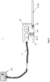
- FIG. 1 shows a first embodiment of a sewer inspection and/or maintenance system according to the invention.
- the inspection system 1 here comprises a base unit 10 designed as a carriage with system components 40, 60a, 60b, 70, 80, 90 arranged on it.
- the base unit 10 is coupled via a communication connection K to a control unit 100, which is usually arranged outside the channel to be inspected or serviced.
- the communication connection K is designed as a wired connection.
- the communication connection K can also be in the form of a wireless connection.
- a wired communication connection it can be advantageous to supply the trolley 10 with electrical energy via the cable.
- a wireless communication connection it has proven to be advantageous to equip the trolley 10 with a battery or with an accumulator—the trolley 10 can thus be operated completely wirelessly.
- the control unit 100 here includes a display device on which the base unit 10 with the system components 40 arranged thereon can be visualized.
- the current configuration of the inspection system can be visualized for the user without having to look at the inspection system directly. The user can then see at a glance whether the inspection system is correctly configured for the planned inspection/maintenance.
- a number of system components 40 are arranged on the trolley 10, namely a base 60a or base unit of a lifting device, a lifting arm 60b of the lifting device, a camera 70, a number of trolley wheels 80, and a temperature measuring device 90.
- other or additional system components 40 can also be attached the carriage 10 are arranged.
- each of the system components has a transponder 30 , for example an RFID transponder, with the transponders 30 being adapted to provide data identifying the respective system component 40 .
- the transponders 30 can be adapted to provide a unique identifier for the respective system component.
- a reading device 20 such as an RFID reading device, is arranged on the base unit or on the carriage 10, with which the data provided by the transponders 30 of the system components 40 can be read out without contact.
- the reading device can read the unique identifier assigned to the respective system component from the RFID transponders.
- a plurality of reading devices 20 can also be distributed on the trolley, for example when the electric or electromagnetic field of a reading device 20 does not reach far enough to reach all of the transponders 30.
- the advantage of using transponders that can be read contactlessly according to the invention is that no electrical plug connections have to be provided between the respective system components and the trolley. This reduces the complexity of the trolley and the system components.
- the system components can be arranged anywhere and flexibly on the trolley without having to take electrical plug connections into account.
- the in 1 shown and designed as a temperature measuring device system component 90 can be attached to any place on the trolley.
- the system components designed as wheels 80 can be mounted on the wheel axles of the trolley in the usual way without having to take any electrical connections into account.
- the avoidance of such electrical contacts also has the advantage that the number of components that are susceptible to wear and require maintenance is reduced or kept low.
- a further advantage of the transponders according to the invention is that contamination has no effect on being able to determine the current configuration of the vehicle, since contamination can pose a considerable problem, particularly in the case of sewer inspection and maintenance systems.
- both the transponder 30 and the reading device 20 can be hermetically protected in the respective system components 40 or in the carriage.
- the wear and tear and external influences, which occur in particular in ducts, can thus be significantly reduced and the service life of the transponders can be significantly increased.
- the transponders can, for example, be housed in a hermetic, i.e. gas and fluid-tight housing.
- the transponders 30 contained in the system components 40 can be active or passive transponders.
- passive transponders such as RFID transponders
- the transponder is supplied with energy by means of the electromagnetic field generated by the reading device 20 and the data is transmitted from the transponder to the reading device.
- active transponders the transponder can be supplied with energy using its own power supply, for example using a battery assigned to the transponder.
- the identifiers (data) of the system components 40 read out from the individual transponders 30 by the reading device 20 are transmitted to the control unit 100 via the communication connection K in a wireless or wired manner.
- the transmission of the data is preferably taken over by a data processing device 50, which is also arranged in the base unit 10 or in the carriage.
- the data processing device 50 is coupled to the reading device 20 and is adapted to process the data provided by the reading device, ie the data that the reading device 20 has read from the respective transponder 30 , and to transmit it to the control unit 100 .
- the processing of the data by the data processing device 50 can include processing according to a predetermined transmission protocol.
- the data processing device 50 can be coupled to a storage device 130 in order to store the data from the reading device, for example when the data cannot be transmitted to the control unit.
- the data processing device 50 can be adapted to monitor the assembly of system components 40 and to inform the worker in the event of incorrect assembly, for example by means of an optical or acoustic signal.
- a number of possible or permissible configurations of the trolley can be stored in the data processing device 50 or in the memory device 130 .
- the data processing device 50 and the memory device 130 can be designed as an integral unit. When a system component is assembled, the data processing device can then carry out a comparison with the stored configurations and, if necessary, inform the worker. This is particularly advantageous when different system components cannot be distinguished from the outside, or can only be distinguished with great difficulty.
- Two wheels with different tire hardnesses can look almost identical, but they may not be used together on one trolley or one of the two wheels on the specific trolley may not be used at all. If the worker would now attach the (impermissible) wheel to the trolley, the reading device 20 can read out the identification of the wheel and the data processing device can carry out a corresponding comparison for this identification.
- the advantage here is that the configuration can already be monitored easily during the set-up time, thus avoiding later set-ups, for example if the carriage first has to be removed from the channel for the set-up.
- the transponders not only provide an identifier for the respective system component 40, but also other data that can be queried by the reading device.
- this further data it can be for example, be sensor data.
- 1 shows an example of a system component 40 designed in this way, namely the system component 90, which is designed as a temperature measuring device.
- the temperature measuring device 90 has a transponder 30 and a temperature sensor 110 .
- the temperature sensor 110 is operatively coupled to the transponder 30 in such a way that the reading device 20 can read not only the identifier of the transponder (or the identifier of the system component 90) but also the measured value provided by the temperature sensor from the transponder.
- angle ⁇ between the system component 70 designed as a camera and the system component 60b designed as a lifting arm is another example of such additional data.
- An angle sensor can be arranged in the camera 70 (or in or on the camera housing), which measures the angle ⁇ between the lifting arm 60b and, for example, the optical axis of the camera 70, and which is operatively coupled to the transponder 30 of the camera 70.
- the angle ⁇ between the lifting arm 60b and the base unit 60a can also be determined with the aid of an angle measuring device and made available to the reading device via the transponder 30 arranged in the base unit 60a for reading out from the transponder.
- the transponders 30 of the system components 40 embodied as wheels 80 can, for example, each be operatively coupled to a tire pressure sensor, so that the reading device 20 can also read out the tire pressure of the respective wheel via the transponder 30 .
- the data processing device 50 can also transmit this additional data to the control unit 100, where it can be visualized if necessary.
- the identifiers of the system components and the other data can be stored in the control unit 100 or also in the storage device 130 of the vehicle for the purpose of complete documentation of a sewer inspection or sewer maintenance.
- the reading device 20 can be adapted to query the identifiers of the transponders and possibly the other data at regular time intervals (e.g. every 5 minutes) and to store them in the memory device 130 or to transmit them to the control unit 100.
- FIG. 2 shows a second embodiment of a sewer inspection and/or maintenance system according to the invention.
- the inspection system 1 here comprises a base unit 10 designed as a sliding system with system components 40, 85, 90 arranged on it.
- the base unit 10 is advanced in the channel by means of a push cable or eel.
- the communication connection K between the base unit 10 and the control unit 100 can be formed in the shifting eel if a wired communication connection K is involved.
- the communication connection K can also be in the form of a wireless connection.
- system components 40 are arranged on the base unit 10, namely a camera 70, a bending rod 85 and a temperature measuring device 90. These three system components are preferably arranged detachably on the base unit 10 and each have a transponder 30.
- a reading device 20 is also arranged on the base unit 10, with which the unique identifiers of the system components 40 or the respective transponder 40 can be queried.
- the reading device 20 can make the queried identifiers available to a data processing device 50, which then transmits this, optionally after processing, to the control unit 100 via the communication link K.
- the in 2 system components 40 shown have sensor devices 110 which can provide further data for querying by the reading device 20 .
- the system component designed as a bending rod 85 can also have a sensor, such as an in 2 not shown angle sensor, with which the angle between the housing of the base unit and the bending stick can be determined.
- the functioning of the reading device 20 and the transponder 30 corresponds to the above 1 described functionality.
- Other or additional sensors can also be provided, the sensor data of which can be queried using the transponder and reading device.
- force sensors can be provided with which the forces acting on the bending rod 85 or with which the tensile forces acting on the push cable or other cables can be measured.
- FIG. 3 shows an example of a detailed view of a system component as a block diagram according to a possible embodiment of the invention.
- the transponder 30 is operatively connected to the sensor device 110 here, with the measured values determined by the sensor device 110 being made available to the transponder 30 as measured data.
- the transponder 30 is also operatively coupled to a memory device 120 here.
- the memory device can be provided to store or temporarily store the measured values of the sensor device 110 .
- the memory device 120 can also store the identifier of the system component 40 or of the transponder 30 .
- the transponder 30 is coupled to a power supply 140 here.
- the power supply can also be coupled to the sensor device 110 and/or the storage device 120 .
- the power supply can be designed as a battery or as an accumulator. With appropriate electronics, the accumulator can obtain the energy required for charging the accumulator from the electric field of the reading device 20 .
- the power supply 140 is particularly advantageous when the transponder 30 is only queried at time intervals, but the measured values of the sensor device are to be recorded continuously (i.e. at shorter time intervals). The measured values can then be temporarily stored in the storage device until the next query.
- the components 30, 110, 120 and 140 can be configured as an integral transponder module 41. Such a transponder module can then easily be arranged or attached to a system component 40 .
- the transponder module 41 can also only have the transponder 30 and the memory device 120 .
- the transponder module can then have a or have multiple interfaces via which one or more sensor devices can be connected to the transponder module 41 .
- FIG. 4 shows three examples of a transponder arranged on the system component, both the system component and the transponder are shown only schematically here.
- Figure (a) of 4 shows a system component 40 in which the transponder 30 is arranged within the system component 40.
- the system component 40 can comprise a housing, within which the transponder 30 is arranged.
- the housing of the system component 40 can be designed to be fluid-tight and/or gas-tight.
- the transponder 30 itself can also comprise a housing within which the electronic components of the transponder are arranged.
- the housing of the transponder can be gas and/or fluid-tight.
- FIG (b) of 4 shows a system component 40 in which the transponder 30 is arranged on the outside of the system component 40 .
- the transponder 30 is designed here as a radio tag that is attached to an outside of the system component 40, for example glued to a housing wall of the system component.
- a transponder designed as a radio tag can also be arranged within the system component, as shown in figure (a) of the 4 shown.
- FIG. c) of 4 shows a system component 40 in which the transponder 30 is arranged on the outside of the system component 40 .
- the transponder 30 is in this case designed as a transponder module which is screwed onto the outside of the system component 40 or mechanically fastened in some other way.
- the transponder module can include a fluid and/or gas-tight housing in which the electronic components of the transponder are arranged.
- the transponder is designed as an RFID transponder and the reading device is designed as an RFID reading device.
- the invention is not limited to RFID technology. Rather, other radio technologies can also be used, for example Bluetooth, Bluetooth Low Energy, ZigBee or NFC.
- any system component can be provided with a transponder or a transponder module.
- the reading device can read out the identification of the transponder and, if necessary, further data (eg sensor data).
- further data eg sensor data
- the user can thus check the configuration of the sewer inspection and/or maintenance system independently of a physical inspection, not only before an inspection and/or maintenance process but during the entire inspection and/or maintenance process. It is particularly advantageous here that no electrical connection or coupling (such as a cable or plug) has to be provided between the system component and the base unit.
Landscapes
- Health & Medical Sciences (AREA)
- Life Sciences & Earth Sciences (AREA)
- Engineering & Computer Science (AREA)
- Hydrology & Water Resources (AREA)
- Public Health (AREA)
- Water Supply & Treatment (AREA)
- Arrangements For Transmission Of Measured Signals (AREA)
Priority Applications (2)
| Application Number | Priority Date | Filing Date | Title |
|---|---|---|---|
| EP21171967.9A EP4086400B1 (fr) | 2021-05-04 | 2021-05-04 | Système d'inspection de canal et/ou de maintenance |
| US17/735,773 US12410601B2 (en) | 2021-05-04 | 2022-05-03 | Sewer inspection and/or maintenance system |
Applications Claiming Priority (1)
| Application Number | Priority Date | Filing Date | Title |
|---|---|---|---|
| EP21171967.9A EP4086400B1 (fr) | 2021-05-04 | 2021-05-04 | Système d'inspection de canal et/ou de maintenance |
Publications (2)
| Publication Number | Publication Date |
|---|---|
| EP4086400A1 true EP4086400A1 (fr) | 2022-11-09 |
| EP4086400B1 EP4086400B1 (fr) | 2023-11-22 |
Family
ID=75801443
Family Applications (1)
| Application Number | Title | Priority Date | Filing Date |
|---|---|---|---|
| EP21171967.9A Active EP4086400B1 (fr) | 2021-05-04 | 2021-05-04 | Système d'inspection de canal et/ou de maintenance |
Country Status (2)
| Country | Link |
|---|---|
| US (1) | US12410601B2 (fr) |
| EP (1) | EP4086400B1 (fr) |
Cited By (1)
| Publication number | Priority date | Publication date | Assignee | Title |
|---|---|---|---|---|
| DE102023124738A1 (de) * | 2023-09-13 | 2025-03-13 | Ipek International Gmbh | Geräteträger für Kanalinspektions- und/oder Wartungssystem |
Families Citing this family (1)
| Publication number | Priority date | Publication date | Assignee | Title |
|---|---|---|---|---|
| DE102023124733A1 (de) * | 2023-09-13 | 2025-03-13 | Ipek International Gmbh | Positionierungssystem für Kanalinspektions- und/oder Wartungssysteme |
Citations (5)
| Publication number | Priority date | Publication date | Assignee | Title |
|---|---|---|---|---|
| DE202011100462U1 (de) * | 2011-05-10 | 2011-07-11 | Ibak Helmut Hunger Gmbh & Co Kg | Kanalrohrroboter |
| DE102011015080A1 (de) | 2011-03-24 | 2012-09-27 | Ipek International Gmbh | Hebeeinheit für Rohrinspektionssysteme |
| DE102012108500B3 (de) | 2012-09-11 | 2014-03-13 | Ipek International Gmbh | Inspektionssystem mit Temperaturmesseinrichtung |
| DE202014105998U1 (de) * | 2014-05-05 | 2015-08-06 | Ipek International Gmbh | System zum Steuern von Inspektions- und/oder Wartungseinheiten |
| DE202015101277U1 (de) * | 2015-03-12 | 2016-06-15 | Ipek International Gmbh | System zur Übertragung von Daten |
Family Cites Families (9)
| Publication number | Priority date | Publication date | Assignee | Title |
|---|---|---|---|---|
| US3400574A (en) * | 1966-10-31 | 1968-09-10 | Harold W. Cramer | Method and apparatus for testing pipelines |
| DE19820783A1 (de) * | 1998-03-23 | 1999-09-30 | Itv Ges Fuer Ind Tv Mbh | System für die Identifizierung eines Hohlraumes |
| DE202012003028U1 (de) * | 2012-03-23 | 2012-04-05 | Ibak Helmut Hunger Gmbh & Co Kg | Kanalrohrinspektionsvorrichtung |
| DE102013211795B4 (de) * | 2013-06-21 | 2020-07-16 | Ibak Helmut Hunger Gmbh & Co. Kg | Kanalrohrroboter mit einer Detektorvorrichtung zum Erkennen von verborgenen Strukturen in oder hinter Kanalrohrwandungen |
| US10641676B1 (en) * | 2016-10-30 | 2020-05-05 | Jason Cruz | Method and apparatus for tracing sewer connections with RFID PIT tags |
| EP3696335B1 (fr) * | 2019-02-13 | 2024-08-07 | iPEK International GmbH | Système d'inspection de canal et/ou de maintenance |
| DE102019108614A1 (de) * | 2019-04-02 | 2019-06-19 | Ipek International Gmbh | System und Verfahren zur Datenübertragung in Rohrinspektions- und/oder Wartungssystemen |
| US12044657B2 (en) * | 2021-10-08 | 2024-07-23 | Saudi Arabian Oil Company | System and method for position tracking of a crawler on a structure |
| DE102022132956A1 (de) * | 2022-12-12 | 2024-06-13 | Jt-Elektronik Gmbh | Kanal- und Schachtinspektionseinheit |
-
2021
- 2021-05-04 EP EP21171967.9A patent/EP4086400B1/fr active Active
-
2022
- 2022-05-03 US US17/735,773 patent/US12410601B2/en active Active
Patent Citations (5)
| Publication number | Priority date | Publication date | Assignee | Title |
|---|---|---|---|---|
| DE102011015080A1 (de) | 2011-03-24 | 2012-09-27 | Ipek International Gmbh | Hebeeinheit für Rohrinspektionssysteme |
| DE202011100462U1 (de) * | 2011-05-10 | 2011-07-11 | Ibak Helmut Hunger Gmbh & Co Kg | Kanalrohrroboter |
| DE102012108500B3 (de) | 2012-09-11 | 2014-03-13 | Ipek International Gmbh | Inspektionssystem mit Temperaturmesseinrichtung |
| DE202014105998U1 (de) * | 2014-05-05 | 2015-08-06 | Ipek International Gmbh | System zum Steuern von Inspektions- und/oder Wartungseinheiten |
| DE202015101277U1 (de) * | 2015-03-12 | 2016-06-15 | Ipek International Gmbh | System zur Übertragung von Daten |
Cited By (1)
| Publication number | Priority date | Publication date | Assignee | Title |
|---|---|---|---|---|
| DE102023124738A1 (de) * | 2023-09-13 | 2025-03-13 | Ipek International Gmbh | Geräteträger für Kanalinspektions- und/oder Wartungssystem |
Also Published As
| Publication number | Publication date |
|---|---|
| US20220356695A1 (en) | 2022-11-10 |
| US12410601B2 (en) | 2025-09-09 |
| EP4086400B1 (fr) | 2023-11-22 |
Similar Documents
| Publication | Publication Date | Title |
|---|---|---|
| DE102014206308B4 (de) | Handhabungsanlage und Verfahren zum Betreiben einer Handhabungsanlage | |
| DE10110776A1 (de) | Verfahren zur Zuordnung einer mobilen Bedien- und/oder Beobachtungseinrichtung zu einer Maschine sowie Bedien- und/oder Beobachtungseinrichtung hierfür | |
| DE102009002762A1 (de) | Gerät zur Überwachung einer oder mehrerer Prozessgrößen | |
| EP3918282B1 (fr) | Module amovible de visualisation et de controle pour un appareil de terrain | |
| EP4086400B1 (fr) | Système d'inspection de canal et/ou de maintenance | |
| EP2792571B1 (fr) | Système de surveillance d'un véhicule ferroviaire | |
| EP3352141A1 (fr) | Procédé et dispositif d'identification d'un dispositif de montage | |
| DE102015226734A1 (de) | Industrielles Gerät und tragbare Vorrichtung | |
| WO2017072042A1 (fr) | Unité de surveillance et agencement d'appareils de terrain muni d'une unité de surveillance | |
| AT521872A1 (de) | Verfahren zum Betreiben eines Maschinensteuerungssystems sowie entsprechendes Maschinensteuerungssystem | |
| DE102005041862A1 (de) | Anordnung zum Bedienen eines Feldgeräts | |
| WO2003016078A1 (fr) | Procede et dispositif permettant de faire fonctionner un equipement de surveillance et de signalisation radio d'un changement de pression et d'effectuer un reglage automatique de la pression des pneumatiques de vehicules automobiles | |
| EP4039550B1 (fr) | Élément d'interface pour un véhicule | |
| DE102007060555A1 (de) | Vorrichtung zur Übertragung von elektrischer Energie und Information | |
| WO2007115636A1 (fr) | Système de préhension à vide comprenant plusieurs emplacements d'aspiration | |
| EP4155846A1 (fr) | Elément de liaison pour établir une liaison filaire entre une première et une deuxième unité | |
| DE202021102381U1 (de) | Kanalinspektions- und/oder Wartungssystem | |
| DE102009040382A1 (de) | Sensor sowie Sensornetzwerk und Verfahren zu dessen Betrieb | |
| DE102011011824A1 (de) | Hubzahlsensor | |
| DE102006023885A1 (de) | Autonome Schlüsselkomponenten für flexible Vakuumgreifer | |
| WO2021047859A1 (fr) | Système de communication et dispositif de machine | |
| DE102012101500A1 (de) | Verfahren und Anordnung zur Erfassung von Zustände eines Fahrzeugs beschreibenden Daten sowie ein entsprechendes Computerprogramm und ein entsprechendes computerlesbares Speichermedium | |
| WO2015110476A1 (fr) | Système adaptateur de communication, pour la technique de commande | |
| EP3259560B1 (fr) | Dispositif de détection | |
| DE20320506U1 (de) | Funkschnittstelle zwischen Fahrzeug und Anhänger |
Legal Events
| Date | Code | Title | Description |
|---|---|---|---|
| PUAI | Public reference made under article 153(3) epc to a published international application that has entered the european phase |
Free format text: ORIGINAL CODE: 0009012 |
|
| STAA | Information on the status of an ep patent application or granted ep patent |
Free format text: STATUS: THE APPLICATION HAS BEEN PUBLISHED |
|
| AK | Designated contracting states |
Kind code of ref document: A1 Designated state(s): AL AT BE BG CH CY CZ DE DK EE ES FI FR GB GR HR HU IE IS IT LI LT LU LV MC MK MT NL NO PL PT RO RS SE SI SK SM TR |
|
| STAA | Information on the status of an ep patent application or granted ep patent |
Free format text: STATUS: REQUEST FOR EXAMINATION WAS MADE |
|
| 17P | Request for examination filed |
Effective date: 20230502 |
|
| RBV | Designated contracting states (corrected) |
Designated state(s): AL AT BE BG CH CY CZ DE DK EE ES FI FR GB GR HR HU IE IS IT LI LT LU LV MC MK MT NL NO PL PT RO RS SE SI SK SM TR |
|
| GRAP | Despatch of communication of intention to grant a patent |
Free format text: ORIGINAL CODE: EPIDOSNIGR1 |
|
| STAA | Information on the status of an ep patent application or granted ep patent |
Free format text: STATUS: GRANT OF PATENT IS INTENDED |
|
| INTG | Intention to grant announced |
Effective date: 20230615 |
|
| GRAS | Grant fee paid |
Free format text: ORIGINAL CODE: EPIDOSNIGR3 |
|
| GRAA | (expected) grant |
Free format text: ORIGINAL CODE: 0009210 |
|
| STAA | Information on the status of an ep patent application or granted ep patent |
Free format text: STATUS: THE PATENT HAS BEEN GRANTED |
|
| AK | Designated contracting states |
Kind code of ref document: B1 Designated state(s): AL AT BE BG CH CY CZ DE DK EE ES FI FR GB GR HR HU IE IS IT LI LT LU LV MC MK MT NL NO PL PT RO RS SE SI SK SM TR |
|
| REG | Reference to a national code |
Ref country code: GB Ref legal event code: FG4D Free format text: NOT ENGLISH |
|
| REG | Reference to a national code |
Ref country code: CH Ref legal event code: EP Ref country code: DE Ref legal event code: R096 Ref document number: 502021002000 Country of ref document: DE |
|
| REG | Reference to a national code |
Ref country code: IE Ref legal event code: FG4D Free format text: LANGUAGE OF EP DOCUMENT: GERMAN |
|
| REG | Reference to a national code |
Ref country code: LT Ref legal event code: MG9D |
|
| REG | Reference to a national code |
Ref country code: NL Ref legal event code: MP Effective date: 20231122 |
|
| PG25 | Lapsed in a contracting state [announced via postgrant information from national office to epo] |
Ref country code: GR Free format text: LAPSE BECAUSE OF FAILURE TO SUBMIT A TRANSLATION OF THE DESCRIPTION OR TO PAY THE FEE WITHIN THE PRESCRIBED TIME-LIMIT Effective date: 20240223 |
|
| PG25 | Lapsed in a contracting state [announced via postgrant information from national office to epo] |
Ref country code: IS Free format text: LAPSE BECAUSE OF FAILURE TO SUBMIT A TRANSLATION OF THE DESCRIPTION OR TO PAY THE FEE WITHIN THE PRESCRIBED TIME-LIMIT Effective date: 20240322 |
|
| PG25 | Lapsed in a contracting state [announced via postgrant information from national office to epo] |
Ref country code: LT Free format text: LAPSE BECAUSE OF FAILURE TO SUBMIT A TRANSLATION OF THE DESCRIPTION OR TO PAY THE FEE WITHIN THE PRESCRIBED TIME-LIMIT Effective date: 20231122 |
|
| PG25 | Lapsed in a contracting state [announced via postgrant information from national office to epo] |
Ref country code: NL Free format text: LAPSE BECAUSE OF FAILURE TO SUBMIT A TRANSLATION OF THE DESCRIPTION OR TO PAY THE FEE WITHIN THE PRESCRIBED TIME-LIMIT Effective date: 20231122 |
|
| PG25 | Lapsed in a contracting state [announced via postgrant information from national office to epo] |
Ref country code: ES Free format text: LAPSE BECAUSE OF FAILURE TO SUBMIT A TRANSLATION OF THE DESCRIPTION OR TO PAY THE FEE WITHIN THE PRESCRIBED TIME-LIMIT Effective date: 20231122 |
|
| PG25 | Lapsed in a contracting state [announced via postgrant information from national office to epo] |
Ref country code: NL Free format text: LAPSE BECAUSE OF FAILURE TO SUBMIT A TRANSLATION OF THE DESCRIPTION OR TO PAY THE FEE WITHIN THE PRESCRIBED TIME-LIMIT Effective date: 20231122 Ref country code: LT Free format text: LAPSE BECAUSE OF FAILURE TO SUBMIT A TRANSLATION OF THE DESCRIPTION OR TO PAY THE FEE WITHIN THE PRESCRIBED TIME-LIMIT Effective date: 20231122 Ref country code: IS Free format text: LAPSE BECAUSE OF FAILURE TO SUBMIT A TRANSLATION OF THE DESCRIPTION OR TO PAY THE FEE WITHIN THE PRESCRIBED TIME-LIMIT Effective date: 20240322 Ref country code: GR Free format text: LAPSE BECAUSE OF FAILURE TO SUBMIT A TRANSLATION OF THE DESCRIPTION OR TO PAY THE FEE WITHIN THE PRESCRIBED TIME-LIMIT Effective date: 20240223 Ref country code: ES Free format text: LAPSE BECAUSE OF FAILURE TO SUBMIT A TRANSLATION OF THE DESCRIPTION OR TO PAY THE FEE WITHIN THE PRESCRIBED TIME-LIMIT Effective date: 20231122 Ref country code: BG Free format text: LAPSE BECAUSE OF FAILURE TO SUBMIT A TRANSLATION OF THE DESCRIPTION OR TO PAY THE FEE WITHIN THE PRESCRIBED TIME-LIMIT Effective date: 20240222 Ref country code: PT Free format text: LAPSE BECAUSE OF FAILURE TO SUBMIT A TRANSLATION OF THE DESCRIPTION OR TO PAY THE FEE WITHIN THE PRESCRIBED TIME-LIMIT Effective date: 20240322 |
|
| PG25 | Lapsed in a contracting state [announced via postgrant information from national office to epo] |
Ref country code: SE Free format text: LAPSE BECAUSE OF FAILURE TO SUBMIT A TRANSLATION OF THE DESCRIPTION OR TO PAY THE FEE WITHIN THE PRESCRIBED TIME-LIMIT Effective date: 20231122 Ref country code: RS Free format text: LAPSE BECAUSE OF FAILURE TO SUBMIT A TRANSLATION OF THE DESCRIPTION OR TO PAY THE FEE WITHIN THE PRESCRIBED TIME-LIMIT Effective date: 20231122 Ref country code: PL Free format text: LAPSE BECAUSE OF FAILURE TO SUBMIT A TRANSLATION OF THE DESCRIPTION OR TO PAY THE FEE WITHIN THE PRESCRIBED TIME-LIMIT Effective date: 20231122 Ref country code: NO Free format text: LAPSE BECAUSE OF FAILURE TO SUBMIT A TRANSLATION OF THE DESCRIPTION OR TO PAY THE FEE WITHIN THE PRESCRIBED TIME-LIMIT Effective date: 20240222 Ref country code: LV Free format text: LAPSE BECAUSE OF FAILURE TO SUBMIT A TRANSLATION OF THE DESCRIPTION OR TO PAY THE FEE WITHIN THE PRESCRIBED TIME-LIMIT Effective date: 20231122 Ref country code: HR Free format text: LAPSE BECAUSE OF FAILURE TO SUBMIT A TRANSLATION OF THE DESCRIPTION OR TO PAY THE FEE WITHIN THE PRESCRIBED TIME-LIMIT Effective date: 20231122 |
|
| PG25 | Lapsed in a contracting state [announced via postgrant information from national office to epo] |
Ref country code: DK Free format text: LAPSE BECAUSE OF FAILURE TO SUBMIT A TRANSLATION OF THE DESCRIPTION OR TO PAY THE FEE WITHIN THE PRESCRIBED TIME-LIMIT Effective date: 20231122 |
|
| PG25 | Lapsed in a contracting state [announced via postgrant information from national office to epo] |
Ref country code: CZ Free format text: LAPSE BECAUSE OF FAILURE TO SUBMIT A TRANSLATION OF THE DESCRIPTION OR TO PAY THE FEE WITHIN THE PRESCRIBED TIME-LIMIT Effective date: 20231122 |
|
| PG25 | Lapsed in a contracting state [announced via postgrant information from national office to epo] |
Ref country code: SK Free format text: LAPSE BECAUSE OF FAILURE TO SUBMIT A TRANSLATION OF THE DESCRIPTION OR TO PAY THE FEE WITHIN THE PRESCRIBED TIME-LIMIT Effective date: 20231122 |
|
| PG25 | Lapsed in a contracting state [announced via postgrant information from national office to epo] |
Ref country code: SM Free format text: LAPSE BECAUSE OF FAILURE TO SUBMIT A TRANSLATION OF THE DESCRIPTION OR TO PAY THE FEE WITHIN THE PRESCRIBED TIME-LIMIT Effective date: 20231122 Ref country code: SK Free format text: LAPSE BECAUSE OF FAILURE TO SUBMIT A TRANSLATION OF THE DESCRIPTION OR TO PAY THE FEE WITHIN THE PRESCRIBED TIME-LIMIT Effective date: 20231122 Ref country code: RO Free format text: LAPSE BECAUSE OF FAILURE TO SUBMIT A TRANSLATION OF THE DESCRIPTION OR TO PAY THE FEE WITHIN THE PRESCRIBED TIME-LIMIT Effective date: 20231122 Ref country code: IT Free format text: LAPSE BECAUSE OF FAILURE TO SUBMIT A TRANSLATION OF THE DESCRIPTION OR TO PAY THE FEE WITHIN THE PRESCRIBED TIME-LIMIT Effective date: 20231122 Ref country code: EE Free format text: LAPSE BECAUSE OF FAILURE TO SUBMIT A TRANSLATION OF THE DESCRIPTION OR TO PAY THE FEE WITHIN THE PRESCRIBED TIME-LIMIT Effective date: 20231122 Ref country code: DK Free format text: LAPSE BECAUSE OF FAILURE TO SUBMIT A TRANSLATION OF THE DESCRIPTION OR TO PAY THE FEE WITHIN THE PRESCRIBED TIME-LIMIT Effective date: 20231122 Ref country code: CZ Free format text: LAPSE BECAUSE OF FAILURE TO SUBMIT A TRANSLATION OF THE DESCRIPTION OR TO PAY THE FEE WITHIN THE PRESCRIBED TIME-LIMIT Effective date: 20231122 |
|
| REG | Reference to a national code |
Ref country code: DE Ref legal event code: R097 Ref document number: 502021002000 Country of ref document: DE |
|
| PLBE | No opposition filed within time limit |
Free format text: ORIGINAL CODE: 0009261 |
|
| STAA | Information on the status of an ep patent application or granted ep patent |
Free format text: STATUS: NO OPPOSITION FILED WITHIN TIME LIMIT |
|
| PG25 | Lapsed in a contracting state [announced via postgrant information from national office to epo] |
Ref country code: SI Free format text: LAPSE BECAUSE OF FAILURE TO SUBMIT A TRANSLATION OF THE DESCRIPTION OR TO PAY THE FEE WITHIN THE PRESCRIBED TIME-LIMIT Effective date: 20231122 |
|
| 26N | No opposition filed |
Effective date: 20240823 |
|
| PG25 | Lapsed in a contracting state [announced via postgrant information from national office to epo] |
Ref country code: SI Free format text: LAPSE BECAUSE OF FAILURE TO SUBMIT A TRANSLATION OF THE DESCRIPTION OR TO PAY THE FEE WITHIN THE PRESCRIBED TIME-LIMIT Effective date: 20231122 |
|
| REG | Reference to a national code |
Ref country code: CH Ref legal event code: PL |
|
| PG25 | Lapsed in a contracting state [announced via postgrant information from national office to epo] |
Ref country code: MC Free format text: LAPSE BECAUSE OF FAILURE TO SUBMIT A TRANSLATION OF THE DESCRIPTION OR TO PAY THE FEE WITHIN THE PRESCRIBED TIME-LIMIT Effective date: 20231122 |
|
| PG25 | Lapsed in a contracting state [announced via postgrant information from national office to epo] |
Ref country code: LU Free format text: LAPSE BECAUSE OF NON-PAYMENT OF DUE FEES Effective date: 20240504 |
|
| PG25 | Lapsed in a contracting state [announced via postgrant information from national office to epo] |
Ref country code: MC Free format text: LAPSE BECAUSE OF FAILURE TO SUBMIT A TRANSLATION OF THE DESCRIPTION OR TO PAY THE FEE WITHIN THE PRESCRIBED TIME-LIMIT Effective date: 20231122 Ref country code: LU Free format text: LAPSE BECAUSE OF NON-PAYMENT OF DUE FEES Effective date: 20240504 Ref country code: CH Free format text: LAPSE BECAUSE OF NON-PAYMENT OF DUE FEES Effective date: 20240531 |
|
| REG | Reference to a national code |
Ref country code: BE Ref legal event code: MM Effective date: 20240531 |
|
| PG25 | Lapsed in a contracting state [announced via postgrant information from national office to epo] |
Ref country code: IE Free format text: LAPSE BECAUSE OF NON-PAYMENT OF DUE FEES Effective date: 20240504 |
|
| PG25 | Lapsed in a contracting state [announced via postgrant information from national office to epo] |
Ref country code: BE Free format text: LAPSE BECAUSE OF NON-PAYMENT OF DUE FEES Effective date: 20240531 |
|
| PGFP | Annual fee paid to national office [announced via postgrant information from national office to epo] |
Ref country code: AT Payment date: 20250721 Year of fee payment: 5 |
|
| PG25 | Lapsed in a contracting state [announced via postgrant information from national office to epo] |
Ref country code: CY Free format text: LAPSE BECAUSE OF FAILURE TO SUBMIT A TRANSLATION OF THE DESCRIPTION OR TO PAY THE FEE WITHIN THE PRESCRIBED TIME-LIMIT; INVALID AB INITIO Effective date: 20210504 |
|
| PG25 | Lapsed in a contracting state [announced via postgrant information from national office to epo] |
Ref country code: HU Free format text: LAPSE BECAUSE OF FAILURE TO SUBMIT A TRANSLATION OF THE DESCRIPTION OR TO PAY THE FEE WITHIN THE PRESCRIBED TIME-LIMIT; INVALID AB INITIO Effective date: 20210504 |
|
| PG25 | Lapsed in a contracting state [announced via postgrant information from national office to epo] |
Ref country code: FI Free format text: LAPSE BECAUSE OF FAILURE TO SUBMIT A TRANSLATION OF THE DESCRIPTION OR TO PAY THE FEE WITHIN THE PRESCRIBED TIME-LIMIT Effective date: 20231122 |
|
| PG25 | Lapsed in a contracting state [announced via postgrant information from national office to epo] |
Ref country code: TR Free format text: LAPSE BECAUSE OF FAILURE TO SUBMIT A TRANSLATION OF THE DESCRIPTION OR TO PAY THE FEE WITHIN THE PRESCRIBED TIME-LIMIT Effective date: 20231122 |
|
| PGFP | Annual fee paid to national office [announced via postgrant information from national office to epo] |
Ref country code: GB Payment date: 20260522 Year of fee payment: 6 |
|
| PGFP | Annual fee paid to national office [announced via postgrant information from national office to epo] |
Ref country code: DE Payment date: 20260522 Year of fee payment: 6 |
|
| PGFP | Annual fee paid to national office [announced via postgrant information from national office to epo] |
Ref country code: FR Payment date: 20260526 Year of fee payment: 6 |