EP4086401A1 - Composant denté thermoisolant et procédé de construction d'une section de bâtiment - Google Patents
Composant denté thermoisolant et procédé de construction d'une section de bâtiment Download PDFInfo
- Publication number
- EP4086401A1 EP4086401A1 EP22170877.9A EP22170877A EP4086401A1 EP 4086401 A1 EP4086401 A1 EP 4086401A1 EP 22170877 A EP22170877 A EP 22170877A EP 4086401 A1 EP4086401 A1 EP 4086401A1
- Authority
- EP
- European Patent Office
- Prior art keywords
- trough
- concrete
- toothed component
- heat
- formwork
- Prior art date
- Legal status (The legal status is an assumption and is not a legal conclusion. Google has not performed a legal analysis and makes no representation as to the accuracy of the status listed.)
- Granted
Links
Images


Classifications
-
- E—FIXED CONSTRUCTIONS
- E04—BUILDING
- E04B—GENERAL BUILDING CONSTRUCTIONS; WALLS, e.g. PARTITIONS; ROOFS; FLOORS; CEILINGS; INSULATION OR OTHER PROTECTION OF BUILDINGS
- E04B1/00—Constructions in general; Structures which are not restricted either to walls, e.g. partitions, or floors or ceilings or roofs
- E04B1/62—Insulation or other protection; Elements or use of specified material therefor
- E04B1/74—Heat, sound or noise insulation, absorption, or reflection; Other building methods affording favourable thermal or acoustical conditions, e.g. accumulating of heat within walls
- E04B1/76—Heat, sound or noise insulation, absorption, or reflection; Other building methods affording favourable thermal or acoustical conditions, e.g. accumulating of heat within walls specifically with respect to heat only
- E04B1/78—Heat insulating elements
-
- E—FIXED CONSTRUCTIONS
- E04—BUILDING
- E04B—GENERAL BUILDING CONSTRUCTIONS; WALLS, e.g. PARTITIONS; ROOFS; FLOORS; CEILINGS; INSULATION OR OTHER PROTECTION OF BUILDINGS
- E04B1/00—Constructions in general; Structures which are not restricted either to walls, e.g. partitions, or floors or ceilings or roofs
- E04B1/62—Insulation or other protection; Elements or use of specified material therefor
- E04B1/74—Heat, sound or noise insulation, absorption, or reflection; Other building methods affording favourable thermal or acoustical conditions, e.g. accumulating of heat within walls
- E04B1/76—Heat, sound or noise insulation, absorption, or reflection; Other building methods affording favourable thermal or acoustical conditions, e.g. accumulating of heat within walls specifically with respect to heat only
- E04B2001/7679—Means preventing cold bridging at the junction of an exterior wall with an interior wall or a floor
Definitions
- the present invention relates to a heat-insulating toothed component for power transmission between two load-bearing concrete components, in particular a vertical building wall and a floor above or below, and a method for creating a building section that comprises two load-bearing concrete components and at least one heat-insulating toothed component arranged between these concrete components.
- load-bearing, vertically aligned concrete components are often created from concrete structures provided with reinforcement.
- a so-called compound joint is formed between the vertically oriented concrete component and the basement slab or between the vertically oriented concrete component and the floor slab.
- the shear forces are caused by a temperature difference between the vertically aligned concrete component and the floor slab and the associated different thermal expansion of the adjacent concrete components in the area of the bonded joint, which results in a relative displacement of the concrete components among themselves.
- These shear forces can, for example, lead to cracking in the concrete in the area of the bonded joint.
- these cracks can negatively affect the appearance of the concrete components, but on the other hand they can also have a negative effect on the statics of the building.
- the floor slab can be connected to the load-bearing, vertically oriented concrete component with continuous reinforcement.
- thermal insulation element made of lightweight concrete for power transmission and thermal insulation between the concrete components.
- This thermal insulation element comprises a base body, which can be arranged between the concrete components and is made of compressive force-transmitting and thermally insulating lightweight concrete, which has two opposing contact surfaces for the concrete components.
- a thermal separation is achieved by the material used (lightweight concrete). Due to the thermal separation, large jumps in temperature occur between the building parts. In the case of large building parts such as a building wall and a floor slab, the associated different thermal expansion can lead to stresses and relative displacements between the concrete components, which can lead to static problems.
- the base body of this thermal insulation element therefore has a plurality of projections which protrude in relation to these contact surfaces.
- these projections enable the formation of a toothed compound joint between the concrete components, through which an introduction of the shear forces that occur is made possible in the adjacent parts of the building.
- the formation of the projections from lightweight concrete, which has a high modulus of elasticity (abbr.: E-modulus) can be achieved with a sufficiently high Relative displacement of the projections with respect to the adjacent concrete component and the resulting shear forces lead to cracking in the adjacent concrete component.
- the present invention is therefore based on the object of specifying a heat-insulating toothed component and a method for the construction of the building section which, compared to the prior art, improves the absorption and transmission of the relative displacement between two concrete components, in particular between a load-bearing, vertically aligned concrete component and a horizontally oriented concrete component, allow resulting shear forces while reducing the heat conduction between the concrete components.
- a plurality of trough elements to be laid individually or in composite groups between the concrete components are provided, which are at least partially made of a heat-insulating material.
- These trough elements each have a trough base, a trough opening opposite the trough base and a wall extending laterally from the trough base to the trough opening.
- the toothed component also comprises a base body which cuts out the trough openings and has a first contact side and a second contact side opposite the first contact side, the trough elements forming projections which protrude in relation to the first contact side.
- the contact sides are used in particular for contact with adjacent in-situ concrete and are designed for this purpose.
- liquid concrete can be poured through the trough openings into the inner area of the trough elements enclosed by the wall and trough base when a building section is constructed that comprises two concrete components and the heat-insulating toothed component arranged between the concrete components and harden there.
- the inner areas of the trough elements are used to hold liquid concrete when the concrete component that rests on the second side of the plant is being created.
- the concrete component adjoining the trough openings or resting on the second contact side and the hardened concrete in the interior are designed in one piece or monolithically.
- the trough elements which protrude at least from the first contact side, thus cause a toothing between the toothed component and the adjacent concrete components transverse to the direction of the compressive force when the toothed component is installed between two concrete components, which ensures that the laterally directed force components are effectively introduced into the adjacent concrete components.
- the base body is at least partially made of a heat-insulating material and therefore reduces the heat conduction between the concrete components when the toothed component is installed.
- Several base bodies can be laid in a line with their short end faces edge to edge without leaving a gap between them.
- the compressive force transmission between the two load-bearing concrete components is distributed linearly over the entire length of the bonded joint instead of on individual support points.
- the end-to-end laying leads to a thermal separation of the adjacent concrete components, which can further reduce heat conduction.
- the base body of the toothed component is preferably cuboid, with its longitudinal axis defining the laying direction of the base body.
- the walls of the trough elements are made of at least one first elastomer. If there is a temperature difference between the adjacent concrete components in the area of the compound joint, this leads to different expansions of the adjacent concrete components. These different expansions result in a relative displacement of the concrete components with one another and the resulting shear forces. Due to the elastic properties of the first elastomer of the wall of the trough elements, these shearing forces can be absorbed at least partially or even completely by deforming the first elastomer and thus the wall. After the shear forces are gone, the wall can return to its original shape due to its elastic properties.
- elastomer is a polymer plastic (artificial or natural origin, such as natural or chloroprene rubber) to understand that is dimensionally stable but at least partially elastically deformable. When the tensile or compressive stress is removed, the polymer returns to its original state. As a result, the first elastomer of the wall is reversibly deformable, which means that the toothed component according to the invention enables improved absorption of the shear forces occurring during the thermally induced relative displacement of the two concrete components with respect to the prior art.
- the trough elements thus form elastomer bearings between the adjacent concrete components.
- the first elastomer also has heat-insulating properties, so that when the toothed component is installed between the concrete components, heat conduction between the concrete components is also reduced in the area of the wall.
- this thermal insulation is not as strong as compared to conventional thermal insulation materials such as duroplastic rigid polyurethane foam or thermoplastic, expanded polystyrene.
- this disadvantage is compensated for by the elastic properties of the first elastomer when absorbing shear forces.
- Another aspect of the present invention provides a method for creating a building section.
- This building section to be created comprises two load-bearing concrete components, in particular a vertically aligned building wall and a floor above or below, and at least one heat-insulating toothed component arranged between the concrete components.
- a first method step (a) of this method a first formwork for a first concrete component and a first reinforcement in the first formwork are first created.
- the first concrete component can be, for example, the load-bearing, vertically aligned building wall.
- liquid concrete is poured into the first formwork, the first formwork either already comprising the toothed component or the toothed component is inserted into the liquid concrete after the liquid concrete has been poured in.
- the liquid concrete surrounds the first reinforcement at least partially or even completely.
- the liquid concrete then hardens in a process step (c). Before hardening the liquid concrete can still be compacted, ie the air content in the still liquid concrete can be reduced. Hydration occurring during hardening is a chemical reaction between cement and water and/or aggregate that can last from several hours to days. In process step (c), this hardening can take place passively, ie essentially without additional heating.
- a second formwork for a second concrete component and a second reinforcement in the second formwork are created.
- the second concrete component can be the floor slab, for example.
- liquid concrete is poured into the second formwork.
- the second formwork is arranged in such a way that when liquid concrete is poured into an interior area of the second formwork, liquid concrete flows over the toothed component and through the openings in the base body and the trough openings into the interior area of the trough elements.
- the liquid concrete then hardens in a process step (f).
- the concrete component adjoining the trough openings or resting on the second contact side and the hardened concrete in the interior are designed in one piece or monolithically.
- the liquid concrete can also be compacted before it hardens.
- a first advantageous embodiment of the toothed component according to the invention provides that the wall of at least one first trough element has a spring stiffness that differs from the spring stiffness of the walls of the other trough elements in each case.
- the deformability and thus the spring stiffness of elastomers depends, among other things, on their density.
- the density of an elastomer can be controlled during manufacture by the amount of blowing agent added. For example, a wall with a lower density of the first elastomer has a low spring stiffness, while a wall with a higher density of the first elastomer has a higher spring stiffness.
- the deformability of elastomers also depends to a large extent on the so-called form factor, i.e. the ratio of the pressed area to the lateral area.
- a large surface area allows the elastomer, which is incompressible per se, to move sideways.
- solid material can be used instead of foamed elastomers by realizing different spring stiffnesses by changing the form factor (knob shapes, additional grooves, etc.).
- the toothed component can also have several trough elements, the first elastomer of which has a different density than the density of the first elastomer of the wall of the respective other trough elements.
- the walls of at least part of the trough elements, seen in the laying direction have a spring stiffness that increases or decreases from trough element to trough element. The selection of the density and thus the spring stiffness of the first elastomer enables a controlled absorption of shear forces of different magnitudes along the bonded joint.
- trough elements are each combined to form a trough element group and the spring stiffness increases or decreases from trough element group to trough element group. This simplifies the manufacture of the trough elements.
- a spring stiffness that ideally increases or decreases linearly
- a desired course of the stiffness can be realized here by a spring stiffness that changes in sections.
- trough elements with 4 or 5 different rigidities can be prefabricated for a building. These can be grouped in 1-2 m pieces and in Composite groups of trough elements are each laid the same stiffness.
- a first of the trough elements can represent an (at least imaginary) zero point of deformation between the adjacent concrete components.
- the corresponding trough element is therefore made more rigid than the other trough elements.
- a temperature difference between the two concrete components leads to increasing relative displacements, which are permitted by the elastomeric bearings and only generate comparatively low restoring forces.
- a decreasing rigidity of the trough elements with increasing distance from the first trough element can therefore be useful.
- the relationship between the distance from the zero point of deformation and the spring stiffness of the elastomeric bearing is therefore inversely proportional.
- the controlled reduction in spring stiffness of the trough elements forming the elastomer bearings can prevent the formation of cracks due to thermal expansion of the adjacent concrete components.
- the spring stiffness can be realized by different densities or different areas or different (geometric) form factors of the trough elements.
- the trough bottoms of the trough elements are made of at least one second elastomer. So that the toothed component in the area of the trough bases can absorb and transmit the vertically acting compressive forces occurring between the concrete components when installed (so-called compressive force transmission), the trough bases preferably have a higher spring stiffness than the adjacent wall. Due to the higher spring stiffness of the trough bottoms compared to their walls, their deformability due to the compressive forces acting is less pronounced. It is within the scope of the invention that the first and the second elastomer are different and can therefore have spring stiffnesses that differ from one another due to the material.
- the first and/or second elastomer have a density in the range from 200 kg/m 3 to 1250 kg/m 3 , preferably from 600 kg/m 3 to 1100 kg/m 3 , particularly preferably 1050 kg/ m3 .
- the base body and/or the trough base has a layered structure which comprises a core layer made of heat-insulating material and/or compressive force-transmitting material and at least one outer layer delimiting the core layer on one side.
- the outer layer is formed from a lubricious material selected from the group consisting of polyethylene, ultra high molecular weight polyethylene (UHMW-PE), polytetrafluoroethylene (PTFE), polyetheretherketone (PEEK) and polyoxymethylene (POM).
- UHMW-PE ultra high molecular weight polyethylene
- PTFE polytetrafluoroethylene
- PEEK polyetheretherketone
- POM polyoxymethylene
- the lubricious material can be applied as a film to the core layer.
- the slippery material can also be sprayed or brushed on.
- the outer layer made of the slippery material decouples the concrete components from each other and allows - as already mentioned - a constraint-free, horizontal relative displacement of the concrete components to each other.
- the shear forces occurring during the relative displacement can be absorbed by the first elastomer of the wall, while at least one concrete component can slide along the outer layer, i.e. parallel to the bonded joint.
- the layered structure can also comprise a second outer layer made of the slippery material and delimiting the core layer on a side of the layered structure opposite the first outer layer.
- the layered structure can also comprise a plurality of outer layers delimiting the core layer on one side or on both sides. This improves the decoupling of the components from one another.
- the heat-insulating and/or compressive-force-transmitting material of the core layer is a third elastomer.
- This third elastomer preferably has a spring stiffness that is higher than the spring stiffness of the first elastomer.
- the first elastomer and/or the second elastomer and/or the third elastomer are preferably selected independently of one another from the group formed by natural rubber, synthetic rubber, in particular ethylene-propylene-diene (monomer) rubber (EPDM), styrene butadiene rubber (SBR), polyurethane elastomer and chlorobutadiene rubber. These elastomers not only have elastic properties, but are also thermally insulating.
- a further advantageous embodiment of the toothed component according to the invention provides that the toothed component is designed in several parts in the manner of a kit, the toothed component being composed of a plurality of individual trough elements and at least one separate base body.
- a kit should also be understood as a gearing component in the sense of the invention and is included in the invention.
- the trough elements can be delivered and installed individually or connected to one another ex works in groups, or delivered individually and connected to one another in groups before installation on the construction site.
- the multi-part design has the advantage that when constructing a building section that has two load-bearing concrete components and at least one heat-insulating toothed component arranged between the concrete components, the trough elements can first be inserted into the still liquid concrete of a first concrete component. Thereafter, the base body is placed on the trough elements and the liquid concrete in such a way that passages formed in the base body are each individually aligned with one of the trough openings. Between the insertion of the trough elements and the placement of the base body, the liquid concrete can still be compacted and/or smoothed out.
- the plurality of individual trough elements and the base body separate from them can be connected to one another during assembly, in particular welded or glued.
- the base body and an outside of the wall facing away from the trough opening of the trough elements enclose an angle ⁇ to one another which is greater than or equal to 90°.
- the angle ⁇ preferably has a value from 90° to 150°, more preferably from 100° to 135° and particularly preferably from 105° to 120°. If the angle ⁇ is greater than 90°, the trough bottom has smaller dimensions than the trough opening.
- the trough bottom and/or the trough opening are designed to be polygonal, elliptical or circular.
- the trough bottom and/or the trough opening have a number of corner points n, which are connected to one another by an identical number of lines m.
- cams these can have a square trough base and can be distributed evenly along at least the first contact side on the base body.
- ribs these extend along at least the first contact side, preferably transversely to the longitudinal axis of the base body, and are in particular open at their short end faces, ie are designed without an end-side extension of the wall.
- the toothed component has at least one rod-shaped force transmission element, which at least traverses the trough floor and can be connected to the concrete components.
- This rod-shaped force transmission element enables a quasi-monolithic connection of the adjacent concrete components, especially in the direction of shear forces. With the help of such a force transmission element, the previously mentioned zero point of deformation can be realized.
- the rod-shaped power transmission element is firmly anchored in the toothed component.
- the rod-shaped force transmission element is preferably a dowel or a reinforcing bar.
- the rod-shaped force transmission element is made of stainless steel or a fiber composite material. As a result, the heat conduction between the concrete components can be further reduced.
- a further advantageous embodiment of the concrete component according to the invention provides that the rod-shaped force transmission element traverses the trough bottom and the trough opening.
- the building section can be created on site at a construction site.
- the first or second formwork, with which the vertically aligned building wall is created is aligned vertically or perpendicularly, so that the liquid concrete can be poured into the formwork, which is open at the top.
- Concrete components can also be produced in a precast concrete plant when the concrete component to be produced is in a lying or horizontal state.
- the vertically oriented building wall can be produced lying flat in the precast concrete plant and then transported to a construction site where the building section is being constructed.
- the first formwork for the horizontal production of one of the two concrete components comprises a substantially horizontally aligned formwork panel with a formwork frame fixed to the formwork panel and protruding from a panel plane of the formwork panel.
- the formwork panel and the formwork frame define an interior area to be filled with concrete.
- the formwork frame has the toothed component as a formwork element.
- concrete is poured into the interior, this concrete is preferably compacted and then hardens.
- the formwork panel and the formwork frame can be removed except for the toothed component and the concrete component can be transferred from its lying position on the formwork panel into a horizontal transport position.
- the concrete component is then ready for installation in the building section.
- the toothed component remains on the concrete component as lost formwork.
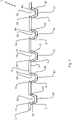
- figure 1 shows a side view of a first embodiment of a heat-insulating toothed component 1 for power transmission between two load-bearing concrete components.
- This toothed component 1 comprises a base body 2 with a first contact side 3 and a second contact side 4 opposite the first contact side 2 for connection to the concrete components.
- the first exemplary embodiment of the toothed component 1 has five trough elements 5 , 6 , 7 , 8 , 9 projecting in relation to the first contact side 3 .
- the first exemplary embodiment of the toothed component 1 is designed in several parts. This means that it is made up of a plurality of individual trough elements 5 , 6 , 7 , 8 , 9 and the separate base body 2 .
- the trough elements 5, 6, 7, 8, 9 each have a trough base 51, 61, 71, 81, 91, a trough opening 52, 62, 72, 82, 92 opposite the trough base 51, 61, 71, 81, 91 and a wall 53, 63, 73, 83, 93 extending laterally from trough floor 51, 61, 71, 81, 91 to trough opening 52, 62, 72, 82, 92.
- trough floor 51, 61, 71, 81, 91 and wall 53, 63, 73, 83, 93 each define an inner region 54, 64, 74, 84, 94 of the trough elements 5, 6, 7, 8, 9.
- the trough openings 52, 62, 72, 82, 92 are each cut out in the base body 2 , in that the base body 2 has passages 21, 22, 23, 24, 25 corresponding to the trough openings 52, 62, 72, 82, 92. Because the trough openings 52, 62, 72, 82, 92 are cut out in the base body, liquid concrete can flow through the trough openings 52, 62, 72, 82, 92 are filled into the inner area 54, 64, 74, 84, 94 of the trough elements 5, 6, 7, 8, 9 and harden in the inner area 54, 64, 74, 84, 94.
- the walls 53, 63, 73, 83, 93 of the trough elements 5, 6, 7, 8, 9 are made of a first elastomer.
- This first elastomer is a polyurethane elastomer.
- the trough floors 51, 61, 71, 81, 91 are formed from a second elastomer, which is also a polyurethane elastomer.
- the first and the second elastomer differ in their stiffness.
- the trough floors 51, 61, 71, 81, 91 have has a higher rigidity than the walls 53, 63, 73, 83, 93.
- the deformability of the trough bases 51, 61, 71, 81, 91 in the installed state of the toothed component 1 between the concrete components due to the vertical compressive forces acting is less pronounced than that of the walls 53, 63, 73, 83, 93.
- figure 2 shows a detail of a second exemplary embodiment of the heat-insulating toothed component 1 in a side view.
- This second embodiment differs from that in figure 1 shown first exemplary embodiment of the toothed component 1 in that the base body 2 and the trough base 51 have a layered structure 10, which comprises a core layer 11 made of heat-insulating material that transmits compressive force and at least one outer layer 12 that delimits the core layer 11 on one side on the second contact side 4.
- the heat-insulating material of the core layer 11 that transmits compressive force is a third elastomer, which in the present second exemplary embodiment can consist of ethylene-propylene-diene (monomer) rubber (EPDM).
- EPDM ethylene-propylene-diene
- the outer layer 12 is formed from a lubricious material such as polytetrafluoroethylene.
- a lubricious material such as polytetrafluoroethylene.
- figure 3 shows a detail of a third exemplary embodiment of the heat-insulating toothed component 1 in a side view.
- This third embodiment differs from that in figure 1 shown first embodiment of the toothed component 1 in that it has a rod-shaped force transmission element 13 in the form of a dowel, which traverses the trough bottom 51 and can be connected to the concrete components.
- this third exemplary embodiment of the toothed component 1 is designed in one piece. This means that the trough elements 5, 6, 7, 8, 9 and the base body 2 are designed in one piece.
- the dowel 13 is firmly anchored in the toothed component 1 and, when the toothed component 1 is installed, enables a quasi-monolithic connection of the adjacent concrete components, especially in the direction of the shear force.
- a building section which comprises two load-bearing concrete components, namely a vertically oriented building wall and a floor slab above it, and a heat-insulating toothed component 1 arranged between the concrete components, can - as described below - be created directly on a construction site: First, a first formwork for created the vertically aligned building wall and a first reinforcement in the first formwork. This first formwork is aligned vertically or perpendicularly, so that liquid in-situ concrete can then be poured from above into the first formwork, which is open at the top. This liquid in-situ concrete is compacted in the conventional way with an internal vibrator. The toothed component 1 is then placed from above onto the liquid, compacted in-situ concrete.
- the liquid in-situ concrete then hardens and the formwork can be removed from the vertically aligned building wall, with the interlocking component 1 remaining on the upper side of the vertical building wall and being used for connection to the floor covering still to be created.
- a second formwork for the horizontally aligned floor slab and a second reinforcement in the second formwork are then created above the vertical building wall. Then liquid in-situ concrete is poured into the second formwork.
- the second formwork is arranged in such a way that when liquid in-situ concrete is poured into an inner area of the second formwork, liquid in-situ concrete flows over the toothed component 1 and through which the trough openings 52, 62, 72, 82, 92 flow into the inner area 54, 64, 74, 84, 94 of the trough elements 5, 6, 7, 8, 9 flows.
- the liquid in-situ concrete is compacted in the conventional way with an internal vibrator. The liquid in-situ concrete then hardens.
- the floor covering adjoining the trough openings 52, 62, 72, 82, 92 or abutting the second contact side 4 and the hardened in-situ concrete in the inner area 54, 64, 74, 84, 94 are designed in one piece or monolithically.
- the vertically oriented building wall is in contact with the first contact side 3 of the base body 2 of the toothed component 1 .
- the horizontally aligned floor slab can be stripped.
- the toothed component 1 is now arranged between the vertically aligned building wall and the overlying horizontally aligned floor slab, so that a toothed composite joint is formed between the two components.
- the trough elements 5, 6, 7, 8, 9 act as an elastomer bearing, so that Shear forces acting parallel to the bonded joint can be absorbed and transmitted.
- the vertically aligned building wall can also be created in advance in a precast concrete plant and then transported to the construction site on which the building section is being created.
- the building wall is manufactured in the lying or horizontal state of the building wall to be manufactured.
- the first formwork comprises a substantially horizontally aligned formwork panel with a formwork frame fixed to the formwork panel and protruding from a panel plane of the formwork panel.
- the formwork panel and the formwork frame define an interior area of this first formwork that is to be filled with concrete.
- the toothed component 1 is part of the formwork frame as a shuttering element. Then liquid concrete is poured into the interior.
- figure 4 shows a side view of an embodiment of the building section 14 created according to the method described above.
- This building section 14 comprises a load-bearing, vertically oriented concrete component 15 in the form of a building wall and a concrete component 16 oriented horizontally above the building wall 15 in the form of a floor slab.
- the toothed component 1 is in figure 1 arranged type shown, whereby a toothed composite joint between the building wall 15 and the floor slab 16 is formed.
- the toothed component 1 can also be arranged between a horizontally oriented basement ceiling and a vertically oriented building wall above it.
- the base body 2 of the toothed component 1 is cuboid, with its longitudinal axis defining the laying direction of the base body 2 along the composite joint.
- the interior 54, 64, 74, 84, 94 of the Trough elements 5, 6, 7, 8, 9 are filled with hardened concrete, this hardened concrete being formed in one piece or monolithically with the hardened concrete of the floor slab 16. If there is a temperature difference between the adjacent concrete components in the area of the compound joint, this leads to different expansions of the adjacent concrete components. These different expansions result in a relative displacement of the concrete components with one another and the resulting shear forces.
- the hardened concrete in the inner area 54, 64, 74, 84, 94 presses against the wall 53, 63, 73, 83, 93 of the trough elements 5, 6, 7, 8, 9. Because of the elastic properties of the first elastomer of the wall 53, 63, 73, 83, 93 of the trough elements 5, 6, 7, 8, 9, these thrust forces can be absorbed at least partially or even completely by deforming the walls 53, 63, 73, 83, 93. After the shearing forces are gone, the wall 53, 63, 73, 83, 93 can resume its original shape due to its elastic properties.
- FIG. 5 A further development of a toothed component 1 is in figure 5 shown in a section. Shown is a section of the base body 2 with a recessed, rib-shaped trough element 5. On the top 4 of the base body 2, two additional longitudinal ribs 17 are formed. These serve as a longitudinal guide for the concrete component to be created above the toothed component 1 .
- a lateral compensating movement is made possible, while forces acting transversely to the concrete component (eg wind pressure) are absorbed by the longitudinal ribs 17 .
- a longitudinal rib 18 is formed within the trough element 5 on the trough bottom 51 thereof.
- the longitudinal rib 18 serves to guide lateral, thermally induced compensatory movements and absorbs compressive forces acting perpendicularly to the concrete component above.
Landscapes
- Physics & Mathematics (AREA)
- Engineering & Computer Science (AREA)
- Architecture (AREA)
- Acoustics & Sound (AREA)
- Electromagnetism (AREA)
- Civil Engineering (AREA)
- Structural Engineering (AREA)
- Road Paving Structures (AREA)
- Building Environments (AREA)
Applications Claiming Priority (1)
| Application Number | Priority Date | Filing Date | Title |
|---|---|---|---|
| DE102021111578.7A DE102021111578A1 (de) | 2021-05-05 | 2021-05-05 | Wärmedämmendes Verzahnungsbauteil und Verfahren zur Erstellung eines Gebäudeabschnitts |
Publications (3)
| Publication Number | Publication Date |
|---|---|
| EP4086401A1 true EP4086401A1 (fr) | 2022-11-09 |
| EP4086401B1 EP4086401B1 (fr) | 2024-06-26 |
| EP4086401C0 EP4086401C0 (fr) | 2024-06-26 |
Family
ID=81449037
Family Applications (1)
| Application Number | Title | Priority Date | Filing Date |
|---|---|---|---|
| EP22170877.9A Active EP4086401B1 (fr) | 2021-05-05 | 2022-04-29 | Composant denté thermoisolant et procédé de construction d'une section de bâtiment |
Country Status (3)
| Country | Link |
|---|---|
| EP (1) | EP4086401B1 (fr) |
| DE (1) | DE102021111578A1 (fr) |
| HU (1) | HUE067765T2 (fr) |
Cited By (1)
| Publication number | Priority date | Publication date | Assignee | Title |
|---|---|---|---|---|
| CH720540A1 (de) * | 2023-02-24 | 2024-08-30 | Profilsager Ag | Schalungselement |
Citations (4)
| Publication number | Priority date | Publication date | Assignee | Title |
|---|---|---|---|---|
| US5491948A (en) * | 1993-12-22 | 1996-02-20 | Harris; Dallas L. | Tilt-up concrete pad and method of forming and erecting the tilt-up concrete pad |
| DE202007012811U1 (de) * | 2007-09-13 | 2008-03-06 | Vysoke uceni technicke v Brne, Fakulta stavebni, ustav pozemniho stavitelstvi | Dämmblockelement zur Unterbrechung von Wärmebrücken im Fußbereich des Mauerwerks |
| EP3467222A1 (fr) * | 2017-10-09 | 2019-04-10 | Schöck Bauteile GmbH | Élément moulé destiné à etre placé entre un mur de construction et une plaque de sol ou de plafond et section de construction pourvue d'un tel élément moulé |
| DE102018130843A1 (de) | 2018-12-04 | 2020-06-04 | Schöck Bauteile GmbH | Vorrichtung zur Wärmeentkopplung zwischen einer betonierten Gebäudewand und einer Geschossdecke sowie Herstellverfahren |
Family Cites Families (1)
| Publication number | Priority date | Publication date | Assignee | Title |
|---|---|---|---|---|
| DE102009022799A1 (de) | 2009-05-27 | 2010-12-09 | Brillux Gmbh & Co. Kg | Verfahren zur Installation von Dämmplatten |
-
2021
- 2021-05-05 DE DE102021111578.7A patent/DE102021111578A1/de not_active Withdrawn
-
2022
- 2022-04-29 EP EP22170877.9A patent/EP4086401B1/fr active Active
- 2022-04-29 HU HUE22170877A patent/HUE067765T2/hu unknown
Patent Citations (4)
| Publication number | Priority date | Publication date | Assignee | Title |
|---|---|---|---|---|
| US5491948A (en) * | 1993-12-22 | 1996-02-20 | Harris; Dallas L. | Tilt-up concrete pad and method of forming and erecting the tilt-up concrete pad |
| DE202007012811U1 (de) * | 2007-09-13 | 2008-03-06 | Vysoke uceni technicke v Brne, Fakulta stavebni, ustav pozemniho stavitelstvi | Dämmblockelement zur Unterbrechung von Wärmebrücken im Fußbereich des Mauerwerks |
| EP3467222A1 (fr) * | 2017-10-09 | 2019-04-10 | Schöck Bauteile GmbH | Élément moulé destiné à etre placé entre un mur de construction et une plaque de sol ou de plafond et section de construction pourvue d'un tel élément moulé |
| DE102018130843A1 (de) | 2018-12-04 | 2020-06-04 | Schöck Bauteile GmbH | Vorrichtung zur Wärmeentkopplung zwischen einer betonierten Gebäudewand und einer Geschossdecke sowie Herstellverfahren |
Cited By (1)
| Publication number | Priority date | Publication date | Assignee | Title |
|---|---|---|---|---|
| CH720540A1 (de) * | 2023-02-24 | 2024-08-30 | Profilsager Ag | Schalungselement |
Also Published As
| Publication number | Publication date |
|---|---|
| DE102021111578A1 (de) | 2022-11-10 |
| EP4086401B1 (fr) | 2024-06-26 |
| HUE067765T2 (hu) | 2024-11-28 |
| EP4086401C0 (fr) | 2024-06-26 |
Similar Documents
| Publication | Publication Date | Title |
|---|---|---|
| DE2135007A1 (de) | Konstruktionselement | |
| EP0059171B1 (fr) | Boulon et canon pour la prise et la transmission d'une force transversale | |
| EP3191657B1 (fr) | Coffrage perdu en béton haute performance ou ultra haute performance | |
| EP4086401B1 (fr) | Composant denté thermoisolant et procédé de construction d'une section de bâtiment | |
| EP3467223B1 (fr) | Élément moulé destiné à etre placé entre un mur de construction et une plaque de sol ou de plafond et section de construction pourvue d'un tel élément moulé | |
| EP3296476B1 (fr) | Dispositif de liaison d'un mur de bâtiment à une dalle de sol ou de plafond et élément de moulage d'un tel système | |
| DE19711813A1 (de) | Thermisch isolierendes Bauelement | |
| EP1525358B1 (fr) | Couche isolante en fibres minerales et paroi de batiment | |
| DE19516098A1 (de) | Deckenrandschalungselement sowie Verfahren und Vorrichtung zu seiner Herstellung | |
| EP1482101A1 (fr) | Elément de construction, procédé pour fabriquer des éléments de construction et moyens de liaison pour élément de construction | |
| AT391731B (de) | Deckenplatte und verfahren zu ihrer herstellung sowie anordnung zur durchfuehrung des verfahrens | |
| EP2088245A1 (fr) | Pont en béton armé ou pont de construction composite avec un joint composite horizontal et son procédé de fabrication | |
| DE102015200661B4 (de) | Verbundfertigteil | |
| EP3569788B1 (fr) | Segment pour un bâtiment, son procédé de fabrication, segment de coin pour un bâtiment, son procédé de fabrication, bâtiment et son procédé de fabrication | |
| EP3789553B1 (fr) | Élément préfabriqué et système préfabriqué | |
| EP3663474B1 (fr) | Dispositif d'isolement thermique entre un mur de bâtiment bétonné et un plancher, ainsi que procédé de fabrication | |
| EP3663475B1 (fr) | Dispositif d'isolement thermique entre un mur de bâtiment bétonné et un plancher, ainsi que procédé de fabrication | |
| EP3912778B1 (fr) | Procédé de fabrication à plat d'une pièce porteuse verticale préfabriquée en béton et pièce porteuse verticale préfabriquée en béton | |
| DE102024111006B4 (de) | Hohldeckenplatte und Verfahren zu ihrer Herstellung | |
| EP3591130B1 (fr) | Structure de plafond | |
| DE8031457U1 (de) | Fuellkoerper fuer waermedaemmende gebaeudedecken | |
| EP3467220B1 (fr) | Partie de bâtiment et procédé de fabrication d'une telle partie de bâtiment | |
| DE102024131757A1 (de) | Bodentiefe Dehnungsfuge | |
| DE202012103496U1 (de) | Wärmedämmendes verlorenes Schalungselement | |
| WO2003038204A1 (fr) | Etanchement de batiments |
Legal Events
| Date | Code | Title | Description |
|---|---|---|---|
| PUAI | Public reference made under article 153(3) epc to a published international application that has entered the european phase |
Free format text: ORIGINAL CODE: 0009012 |
|
| STAA | Information on the status of an ep patent application or granted ep patent |
Free format text: STATUS: THE APPLICATION HAS BEEN PUBLISHED |
|
| AK | Designated contracting states |
Kind code of ref document: A1 Designated state(s): AL AT BE BG CH CY CZ DE DK EE ES FI FR GB GR HR HU IE IS IT LI LT LU LV MC MK MT NL NO PL PT RO RS SE SI SK SM TR |
|
| STAA | Information on the status of an ep patent application or granted ep patent |
Free format text: STATUS: REQUEST FOR EXAMINATION WAS MADE |
|
| 17P | Request for examination filed |
Effective date: 20230201 |
|
| RBV | Designated contracting states (corrected) |
Designated state(s): AL AT BE BG CH CY CZ DE DK EE ES FI FR GB GR HR HU IE IS IT LI LT LU LV MC MK MT NL NO PL PT RO RS SE SI SK SM TR |
|
| GRAP | Despatch of communication of intention to grant a patent |
Free format text: ORIGINAL CODE: EPIDOSNIGR1 |
|
| STAA | Information on the status of an ep patent application or granted ep patent |
Free format text: STATUS: GRANT OF PATENT IS INTENDED |
|
| INTG | Intention to grant announced |
Effective date: 20240412 |
|
| GRAS | Grant fee paid |
Free format text: ORIGINAL CODE: EPIDOSNIGR3 |
|
| GRAA | (expected) grant |
Free format text: ORIGINAL CODE: 0009210 |
|
| STAA | Information on the status of an ep patent application or granted ep patent |
Free format text: STATUS: THE PATENT HAS BEEN GRANTED |
|
| AK | Designated contracting states |
Kind code of ref document: B1 Designated state(s): AL AT BE BG CH CY CZ DE DK EE ES FI FR GB GR HR HU IE IS IT LI LT LU LV MC MK MT NL NO PL PT RO RS SE SI SK SM TR |
|
| REG | Reference to a national code |
Ref country code: GB Ref legal event code: FG4D Free format text: NOT ENGLISH |
|
| REG | Reference to a national code |
Ref country code: CH Ref legal event code: EP |
|
| REG | Reference to a national code |
Ref country code: DE Ref legal event code: R096 Ref document number: 502022001106 Country of ref document: DE |
|
| U01 | Request for unitary effect filed |
Effective date: 20240626 |
|
| U07 | Unitary effect registered |
Designated state(s): AT BE BG DE DK EE FI FR IT LT LU LV MT NL PT SE SI Effective date: 20240701 |
|
| PG25 | Lapsed in a contracting state [announced via postgrant information from national office to epo] |
Ref country code: HR Free format text: LAPSE BECAUSE OF FAILURE TO SUBMIT A TRANSLATION OF THE DESCRIPTION OR TO PAY THE FEE WITHIN THE PRESCRIBED TIME-LIMIT Effective date: 20240626 |
|
| PG25 | Lapsed in a contracting state [announced via postgrant information from national office to epo] |
Ref country code: NO Free format text: LAPSE BECAUSE OF FAILURE TO SUBMIT A TRANSLATION OF THE DESCRIPTION OR TO PAY THE FEE WITHIN THE PRESCRIBED TIME-LIMIT Effective date: 20240926 Ref country code: HR Free format text: LAPSE BECAUSE OF FAILURE TO SUBMIT A TRANSLATION OF THE DESCRIPTION OR TO PAY THE FEE WITHIN THE PRESCRIBED TIME-LIMIT Effective date: 20240626 Ref country code: RS Free format text: LAPSE BECAUSE OF FAILURE TO SUBMIT A TRANSLATION OF THE DESCRIPTION OR TO PAY THE FEE WITHIN THE PRESCRIBED TIME-LIMIT Effective date: 20240926 |
|
| REG | Reference to a national code |
Ref country code: HU Ref legal event code: AG4A Ref document number: E067765 Country of ref document: HU |
|
| PG25 | Lapsed in a contracting state [announced via postgrant information from national office to epo] |
Ref country code: PL Free format text: LAPSE BECAUSE OF FAILURE TO SUBMIT A TRANSLATION OF THE DESCRIPTION OR TO PAY THE FEE WITHIN THE PRESCRIBED TIME-LIMIT Effective date: 20240626 |
|
| PG25 | Lapsed in a contracting state [announced via postgrant information from national office to epo] |
Ref country code: IS Free format text: LAPSE BECAUSE OF FAILURE TO SUBMIT A TRANSLATION OF THE DESCRIPTION OR TO PAY THE FEE WITHIN THE PRESCRIBED TIME-LIMIT Effective date: 20241026 |
|
| PG25 | Lapsed in a contracting state [announced via postgrant information from national office to epo] |
Ref country code: CZ Free format text: LAPSE BECAUSE OF FAILURE TO SUBMIT A TRANSLATION OF THE DESCRIPTION OR TO PAY THE FEE WITHIN THE PRESCRIBED TIME-LIMIT Effective date: 20240626 |
|
| PG25 | Lapsed in a contracting state [announced via postgrant information from national office to epo] |
Ref country code: RO Free format text: LAPSE BECAUSE OF FAILURE TO SUBMIT A TRANSLATION OF THE DESCRIPTION OR TO PAY THE FEE WITHIN THE PRESCRIBED TIME-LIMIT Effective date: 20240626 Ref country code: SK Free format text: LAPSE BECAUSE OF FAILURE TO SUBMIT A TRANSLATION OF THE DESCRIPTION OR TO PAY THE FEE WITHIN THE PRESCRIBED TIME-LIMIT Effective date: 20240626 |
|
| PG25 | Lapsed in a contracting state [announced via postgrant information from national office to epo] |
Ref country code: ES Free format text: LAPSE BECAUSE OF FAILURE TO SUBMIT A TRANSLATION OF THE DESCRIPTION OR TO PAY THE FEE WITHIN THE PRESCRIBED TIME-LIMIT Effective date: 20240626 Ref country code: SM Free format text: LAPSE BECAUSE OF FAILURE TO SUBMIT A TRANSLATION OF THE DESCRIPTION OR TO PAY THE FEE WITHIN THE PRESCRIBED TIME-LIMIT Effective date: 20240626 |
|
| PG25 | Lapsed in a contracting state [announced via postgrant information from national office to epo] |
Ref country code: SM Free format text: LAPSE BECAUSE OF FAILURE TO SUBMIT A TRANSLATION OF THE DESCRIPTION OR TO PAY THE FEE WITHIN THE PRESCRIBED TIME-LIMIT Effective date: 20240626 Ref country code: SK Free format text: LAPSE BECAUSE OF FAILURE TO SUBMIT A TRANSLATION OF THE DESCRIPTION OR TO PAY THE FEE WITHIN THE PRESCRIBED TIME-LIMIT Effective date: 20240626 Ref country code: RO Free format text: LAPSE BECAUSE OF FAILURE TO SUBMIT A TRANSLATION OF THE DESCRIPTION OR TO PAY THE FEE WITHIN THE PRESCRIBED TIME-LIMIT Effective date: 20240626 Ref country code: PL Free format text: LAPSE BECAUSE OF FAILURE TO SUBMIT A TRANSLATION OF THE DESCRIPTION OR TO PAY THE FEE WITHIN THE PRESCRIBED TIME-LIMIT Effective date: 20240626 Ref country code: IS Free format text: LAPSE BECAUSE OF FAILURE TO SUBMIT A TRANSLATION OF THE DESCRIPTION OR TO PAY THE FEE WITHIN THE PRESCRIBED TIME-LIMIT Effective date: 20241026 Ref country code: ES Free format text: LAPSE BECAUSE OF FAILURE TO SUBMIT A TRANSLATION OF THE DESCRIPTION OR TO PAY THE FEE WITHIN THE PRESCRIBED TIME-LIMIT Effective date: 20240626 Ref country code: CZ Free format text: LAPSE BECAUSE OF FAILURE TO SUBMIT A TRANSLATION OF THE DESCRIPTION OR TO PAY THE FEE WITHIN THE PRESCRIBED TIME-LIMIT Effective date: 20240626 |
|
| U20 | Renewal fee for the european patent with unitary effect paid |
Year of fee payment: 4 Effective date: 20250304 |
|
| PLBE | No opposition filed within time limit |
Free format text: ORIGINAL CODE: 0009261 |
|
| STAA | Information on the status of an ep patent application or granted ep patent |
Free format text: STATUS: NO OPPOSITION FILED WITHIN TIME LIMIT |
|
| 26N | No opposition filed |
Effective date: 20250327 |
|
| PGFP | Annual fee paid to national office [announced via postgrant information from national office to epo] |
Ref country code: CH Payment date: 20250501 Year of fee payment: 4 |
|
| PG25 | Lapsed in a contracting state [announced via postgrant information from national office to epo] |
Ref country code: HU Free format text: LAPSE BECAUSE OF NON-PAYMENT OF DUE FEES Effective date: 20250430 |
|
| PG25 | Lapsed in a contracting state [announced via postgrant information from national office to epo] |
Ref country code: MC Free format text: LAPSE BECAUSE OF FAILURE TO SUBMIT A TRANSLATION OF THE DESCRIPTION OR TO PAY THE FEE WITHIN THE PRESCRIBED TIME-LIMIT Effective date: 20240626 |
|
| U20 | Renewal fee for the european patent with unitary effect paid |
Year of fee payment: 5 Effective date: 20260206 |
|
| PGFP | Annual fee paid to national office [announced via postgrant information from national office to epo] |
Ref country code: GB Payment date: 20260324 Year of fee payment: 5 |
|
| PG25 | Lapsed in a contracting state [announced via postgrant information from national office to epo] |
Ref country code: IE Free format text: LAPSE BECAUSE OF NON-PAYMENT OF DUE FEES Effective date: 20250429 |