EP4086477A1 - Boéte de vitesses - Google Patents
Boéte de vitesses Download PDFInfo
- Publication number
- EP4086477A1 EP4086477A1 EP22170003.2A EP22170003A EP4086477A1 EP 4086477 A1 EP4086477 A1 EP 4086477A1 EP 22170003 A EP22170003 A EP 22170003A EP 4086477 A1 EP4086477 A1 EP 4086477A1
- Authority
- EP
- European Patent Office
- Prior art keywords
- bearing
- tooth
- teeth
- transmission according
- side edge
- Prior art date
- Legal status (The legal status is an assumption and is not a legal conclusion. Google has not performed a legal analysis and makes no representation as to the accuracy of the status listed.)
- Granted
Links
Images

Classifications
-
- F—MECHANICAL ENGINEERING; LIGHTING; HEATING; WEAPONS; BLASTING
- F16—ENGINEERING ELEMENTS AND UNITS; GENERAL MEASURES FOR PRODUCING AND MAINTAINING EFFECTIVE FUNCTIONING OF MACHINES OR INSTALLATIONS; THERMAL INSULATION IN GENERAL
- F16H—GEARING
- F16H49/00—Other gearings
-
- F—MECHANICAL ENGINEERING; LIGHTING; HEATING; WEAPONS; BLASTING
- F16—ENGINEERING ELEMENTS AND UNITS; GENERAL MEASURES FOR PRODUCING AND MAINTAINING EFFECTIVE FUNCTIONING OF MACHINES OR INSTALLATIONS; THERMAL INSULATION IN GENERAL
- F16H—GEARING
- F16H25/00—Gearings comprising primarily only cams, cam-followers and screw-and-nut mechanisms
- F16H25/04—Gearings comprising primarily only cams, cam-followers and screw-and-nut mechanisms for conveying rotary motion
- F16H25/06—Gearings comprising primarily only cams, cam-followers and screw-and-nut mechanisms for conveying rotary motion with intermediate members guided along tracks on both rotary members
-
- F—MECHANICAL ENGINEERING; LIGHTING; HEATING; WEAPONS; BLASTING
- F16—ENGINEERING ELEMENTS AND UNITS; GENERAL MEASURES FOR PRODUCING AND MAINTAINING EFFECTIVE FUNCTIONING OF MACHINES OR INSTALLATIONS; THERMAL INSULATION IN GENERAL
- F16H—GEARING
- F16H25/00—Gearings comprising primarily only cams, cam-followers and screw-and-nut mechanisms
- F16H25/08—Gearings comprising primarily only cams, cam-followers and screw-and-nut mechanisms for interconverting rotary motion and reciprocating motion
- F16H25/14—Gearings comprising primarily only cams, cam-followers and screw-and-nut mechanisms for interconverting rotary motion and reciprocating motion with reciprocation perpendicular to the axis of rotation
Definitions
- the invention relates to a gear, a use of a gear.
- Transmissions are known from the prior art which comprise teeth which are mounted in a radially displaceable manner in a tooth carrier.
- Drive elements with a profile such as cam discs, are used to drive the teeth.
- the teeth engage in a toothing, so that there is a relative movement between the tooth carrier with the teeth and the toothing.
- the relative movement between the toothing and the teeth is smaller by at least one order of magnitude than the movement of the drive element with the profile. In this way, high translations can be achieved.
- a critical point of these gears is the axial bearing of the bearing segments. It is known to use thrust washers on the side of the bearing segments, an example of such a transmission is in DE 10 2015 105 520 A1 shown. However, unwanted wear can occur.
- the object of the invention is to specify transmissions which are improved compared to transmissions known from the prior art, with reduced wear or simple assembly being to be achieved.
- One aspect of the invention relates to a transmission, in particular a coaxial transmission or linear transmission, with a tooth system, a tooth carrier in which a plurality of teeth are accommodated for engaging with the tooth system, the teeth being mounted so as to be radially displaceable relative to the tooth carrier, a drive element with a Profiling for the radial drive of the radially displaceably mounted teeth, and bearing segments for mounting the teeth on the profiling, each of the bearing segments comprising: a running side aligned in the direction of the profiling and a bearing side opposite the running side, a toothed bearing arranged on the bearing side for the articulated mounting of at least one of the teeth, wherein the toothed bearing comprises an at least essentially cylinder section-shaped bead, which is arranged in a direction transverse to a running direction of the bearing segment from a first side edge to a second side edge of the bearing segment, and wherein the The bead is arranged in a central region between the first side edge and the second side edge and has a
- the toothed bearing is aligned in an articulated manner about an axis transverse to the running direction of the bearing segment.
- the bearing segment has a running direction in the direction of rotation of the transmission.
- the bead is arranged at least essentially centrally between the front and rear edges of the bearing segment. Typical ridges of embodiments do not extend the full length from one side edge to another side edge of the bearing pads. In other embodiments, the bead extends to both side edges.
- recesses are provided on either side of a central portion of the bead. In typical embodiments, there can be at least one recess in the central region of the bead, or there can be two recesses, for example.
- a further aspect of the invention relates to the use of a transmission in one of the typical embodiments.
- a retaining ring is pressed onto the tooth in the area of the tooth base or pedestal of the tooth, the retaining ring being attached to the tooth solely or at least partially by the press fit.
- the tooth is typically designed at least essentially as a round tooth, at least in one area of a tooth body.
- the tooth has a recess at the tooth base for engagement with the bead of the bearing segment, the bead allowing the tooth to pivot relative to the bearing segment, the tooth however holding the bearing segment in its position relative to the tooth in the circumferential direction.
- the bearing segment can also be referred to as a pivoting segment.
- cylinder segment-shaped typically refers to an angular segment of a lateral surface of a circular cylinder.
- the angular section comprises a minimum of 50° or a maximum of 200°.
- Recesses in particular in the bead, are made in the bearing segment, with the retaining ring engaging in the recesses.
- the bearing segment is supported on the retaining ring in the axial direction.
- the retaining ring is in turn supported by the tooth in the axial direction.
- the tooth cannot move in the axial direction in the tooth carrier and transfers the supporting forces to the tooth carrier.
- the cross section of the retaining ring may be increased in embodiments by providing a shoulder at the tooth base of the tooth.
- directional information relates to the transmission, ie, for example, the axial direction is aligned in the direction of the axis of rotation of the transmission.
- the tooth typically includes a tooth tip, which is intended to engage the toothing, an intermediate part of the tooth, which extends between the tooth tip and the tooth base, and a tooth base, which can also be referred to as a tooth root, which is intended to bear on the tooth bearing of the bearing segment is.
- a tooth tip which is intended to engage the toothing
- an intermediate part of the tooth which extends between the tooth tip and the tooth base
- a tooth base which can also be referred to as a tooth root, which is intended to bear on the tooth bearing of the bearing segment is.
- the base of the tooth and the tip of the tooth are at different ends of the tooth.
- the base of the tooth can rest against the tooth bearing of the bearing segment.
- Embodiments of the invention relate in particular to coaxial transmissions.
- Transmissions of the invention usually include an internal cam disk with a profile as a drive element and a ring gear with an internal toothing or an external drive element with an internal profile and an internal gear wheel or an internal toothed rack, which provides the toothing for the case of the external drive element.
- Configurations of embodiments relate to linear gears for converting a rotation into a linear movement.
- the toothing is typically a circumferential toothing.
- the teeth or the tips of the teeth of the teeth engage in the toothing, with the teeth typically being mounted in a linear, radially displaceable manner relative to the tooth carrier.
- “linear radial” usually means that there is guidance in the radial direction, which only allows the tooth to move in the radial direction.
- the guide allows the toothed segment to be linearly displaced in exactly one direction; this can be achieved, for example, by the tooth having a constant cross-section in the direction of displacement over a certain distance, with the tooth carrier also having an opening for the toothed segment with a constant cross-section.
- the teeth are usually mounted in the tooth carrier so that they can be displaced in exactly one direction, typically in the direction of the longitudinal axis of the tooth. Furthermore, in typical embodiments, the rotational degree of freedom of the teeth is locked relative to the tooth carrier about the longitudinal axis of the gear. This can be achieved, for example, with a linear guidance of the teeth in the radial direction in the tooth carrier. In this way, the teeth rotate with the rack about the longitudinal axis of the gear, but not relative to the rack.
- At least some of the teeth are designed to be rigid.
- the term "rigid is typically to be understood technically, that is, that bends in the teeth are so small due to the rigidity of the material of the teeth that they are at least essentially insignificant for the kinematics of the transmission.
- Rigid teeth include, in particular, teeth which consist of a metal alloy, in particular steel or a titanium alloy, a nickel alloy or other alloys.
- rigid teeth made of plastic can also be provided, in particular in transmissions in which at least one of the following parts is also made of plastic: toothing on a ring gear or a toothed wheel, tooth carrier and drive element.
- the tooth carrier and the teeth are made of a metal alloy or the teeth or the drive element are also made of a metal alloy.
- uch gears offer the advantage that they are extremely torsionally rigid and highly resilient.
- Plastic gears offer the advantage that they are light in weight.
- the term "rigid" means in particular a flexural rigidity about a transverse axis of the toothed segment.
- the bearing segments preferably have mutually facing edges with elevations and depressions, for example a wavy shape or a jagged shape. This offers the advantage that needle rollers, which are arranged below the bearing segments, are reliably held in the space between the bearing segments and the drive element, even when there is a greater distance between the bearing segments.
- the bearing segments can be mounted directly on the profiling of the cam disk.
- Typical embodiments of the invention include a drive element with a profile.
- the profiling preferably has a non-circular or non-ellipsoidal arch shape or curve. Fall within the meaning of this application Eccentrics are also classified under circular or ellipsoidal shapes, since with eccentrics only the axis of rotation does not correspond to the central axis of the circular shape, but a circular shape is nevertheless present.
- the tooth carrier or the teeth are circular. This offers the advantage of a simple geometry for the tooth carrier and the toothing.
- the power transmission takes place on the low-speed side of the transmission between the toothing and the tooth carrier. This offers the advantage that the path for power transmission is extremely short, so that extremely high rigidity can be achieved.
- Embodiments that meet these conditions are in a non-exhaustive version: Transmission with an internal cam as a drive and an external ring gear with teeth, the toothed carrier being arranged between the ring gear and the cam disc; External cam disc with internal profiling on a ring gear for driving the radially movable teeth inwards against a toothing which is arranged on a gear wheel or a rack.
- the bearing pads are circumferentially movable relative to one another.
- the bearing segments can, for example, have a distance between them which is determined by the radial position of the teeth.
- the beads are formed in such a way that the axis of rotation of the tooth on the bead coincides at least substantially with the running side.
- “substantially” means, for example, that the axis of rotation is at most 50% or at most 30% or at most 20% or at most 10% of the diameter of a rolling body above or below the running side. In further embodiments, the axis of rotation is at most 20%, 10% or 5% of the maximum extension of the bearing segment away from the running side in the radial direction.
- bulges of embodiments have lateral flanks toward the recesses, which run straight in the circumferential direction at least in sections or run in a circle at least in sections.
- the flank can also be understood as the interface between the bead and the recess or as the lateral delimitation of the bead.
- the shape of the flank is typically adapted to a shape of a retaining ring.
- a retaining ring is provided for each tooth, which at least partially encloses a tooth base of the respective tooth.
- a retaining ring is provided for at least two teeth, which at least partially encloses the tooth base of the respective teeth.
- the bearing segment can be supported in the axial direction via the tooth or the teeth with the retaining ring.
- the retaining ring is made of steel, but it can also be made of comparatively lighter plastic or as a bent sheet metal part.
- a retaining ring made of steel has a high load-bearing capacity and is inexpensive to manufacture.
- a shoulder is provided on an outer periphery of the tooth or teeth at the base of the tooth for receiving the retaining ring. With the heel, the space requirement can be reduced. Typically, the shoulder steps inward so that the tooth has a reduced diameter at the tooth base.
- Typical teeth of embodiments have a circular cross-section. Due to the retaining ring in interaction with the bead and the internal toothing, complex additional guide or support elements can be at least largely dispensed with in embodiments.
- the retaining ring is ring-shaped.
- the ring shape can be flattened or circular.
- Further retaining rings of embodiments are angular, for example designed as a square, or have several ring-shaped sections.
- sections of an outer circumference of the retaining ring are straight.
- a retaining ring shaped as a circular ring with flat areas on the inner circumference or on the outer circumference can be provided. Collisions between adjacent retaining rings can be avoided with flat areas on the outer circumference.
- a first stop is formed on the bearing side of the bearing segment between the first recess and the first side edge, or a second stop is formed between the second recess and the second side edge. Additional recesses can be provided. the In typical embodiments, the maximum length of a bead between two recesses is the tooth width or the tooth diameter. In embodiments with two teeth arranged in parallel on a bearing segment, at least one recess or at least one stop is optionally provided between the areas in which the teeth rest on the respective bead. Typically, at least two recesses are provided with at least one stop between the recesses, particularly in an area between the teeth. Stops of embodiments can be formed in particular by further bead sections, for example between two teeth or in an area between a bead supporting a tooth and the respective side edge.
- the retaining ring can be supported on the stops of the bearing segment, in particular over its outer circumference.
- a retaining ring for two teeth with two recesses for engagement of the teeth can be provided.
- the retaining ring surrounds a bead of the bearing segment so that it can be supported in the axial direction on the toothed segments via the retaining ring.
- a clearance can be provided between the teeth and the retaining ring in order to compensate for tolerances, for example in the distance between the rows of teeth.
- the retaining ring secures the respective bearing segment in its position transverse to the direction of rotation by engaging in the at least one recess or by engaging with the flanks of the bead.
- Typical embodiments include two recesses per tooth.
- the axial length of the bead of the bearing segment corresponds at most to an inner diameter of the retaining ring.
- the retaining ring grips the bead or a portion of the bead between two recesses.
- the recesses between the teeth and respective side edges range from the region of the bead supporting the tooth to the respective side edges, e.g. the first Recess up to the first side edge and the second recess up to the second side edge.
- exactly one tooth can be mounted on a bearing segment, or exactly two teeth can be mounted on a bearing segment.
- the teeth are typically arranged next to one another and the bead has at least one, typically exactly two, interruptions.
- the 1 shows a schematic section of a transmission 1, which has a ring gear 3 with an internal toothing 5 running around.
- teeth 7 engage.
- the teeth 7 are mounted in a tooth carrier 11 so that they can be moved radially.
- the tooth carrier 11 has radially aligned, channel-like, round or slot-like openings, which ensure radial guidance of the teeth 7 in the tooth carrier 11 . Due to the radial guidance in the openings, it is only possible for the teeth 7 to move in the radial direction along their longitudinal axis; in particular, rotation about a longitudinal axis of the transmission 1 relative to the tooth carrier 11 is ruled out.
- the longitudinal axis of the teeth typically designates the axis running from the tooth base to the tooth tip, while the longitudinal axis of the gear points in the direction of the axis of rotation of the gear.
- This can be, for example, the axis of rotation of the toothed carrier that can be used as an output or the axis of rotation of a cam disc.
- the teeth 7 are driven by a cam disk 20 which is designed as a hollow cam disk 20 .
- the cam disk 20 has a profile 22 in order to drive the teeth 7 in the radial direction.
- the profiling 22 has a course with two elevations over the circumference, so that it is opposite There are teeth 7 that have entered the tooth gaps of the teeth 5 furthest in the representation.
- the teeth 7 are at the in 1 Gear 1 shown arranged with a roller bearing on the profiling of the drive element.
- the rolling bearing includes rolling elements 23, which are designed as needle rollers in this embodiment.
- the cam disk is arranged on the inside and the toothing is arranged on the outside.
- the output is tapped on the ring gear with the teeth or on the toothed carrier, with the respective other element being fixed.
- the drive element is arranged on the outside, ie outside of the tooth carrier, and the toothing is arranged on the inside. Again, it is possible to pick up the output at the internal toothing or at the tooth carrier.
- the function of input and output can be interchanged.
- the tooth carrier can also be referred to as a tooth cage with its openings, in which teeth are accommodated in a radially linearly displaceable manner.
- the transmission 1 comprises a segmented bearing for the teeth 7.
- the segmented bearing comprises bearing segments 24, each of which on the bearing side facing the tooth 7 forms a bead 26 which is at least essentially in the shape of a section of a cylinder and on which the base of two teeth 7 (see 3 ) or in typical embodiments one, three or four teeth can be arranged side by side in the axial direction of the transmission 1 .
- Ankle joints for the teeth 7 are formed with the beads 26, so that the teeth 7 can tilt relative to the bearing segments 24 in order to ensure unconstrained guidance.
- the bearing segments 24 can be displaced relative to one another in the direction of rotation, so that the distances between the bearing segments 24 can be changed. In this way, the degree of freedom in the direction of rotation of the bearing segments 24 is not blocked. This enables a largely free guidance and a largely free radial drive of the bearing segments 24 by the profile 22 of the cam 20.
- the rolling elements 23 are provided as needle rollers.
- balls or other roller bearings are provided for supporting bearing segments.
- a plain bearing between the profile 22 and the bearing segments 24 can be provided.
- the bearing segment 24 includes a bead 26 on the side of the bearing segment 24 facing a tooth 7 in the transmission 1.
- the round surface section of the bead 26 is designed circular.
- the center of the circle coincides with a running side 30 of the bearing segment 24 .
- an axis of rotation 32 is created for the teeth 7, which are mounted on the bearing segments 24, which axis coincides with the running side 30. In this way, the teeth 7 are each articulated on a bearing segment.
- the running side 30 is the side of the bearing segment 24 facing away from the tooth, that is to say the side which faces the rolling element 23 or the cam disk 20 .
- the running side 30 corresponds to the surface on which the rolling elements 23 roll.
- the bearing segment 24 includes a front edge 34 and a rear edge 36.
- the designations "front” and “rear” are not meant in the sense of a movement, rather they refer to two opposite sides of the bearing segment 24 in the direction of rotation.
- Typical transmissions can be operated in two directions, so that during operation the front segment edge can also be at the back in the direction of movement during circulation and accordingly the rear segment edge can be at the front.
- a peripheral shoulder 42 is provided around a foot or at a tooth base of the tooth 7 , which shoulder is encompassed by a retaining ring 40 .
- the retaining rings are associated with the 3 described in more detail.
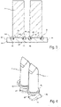
- FIG. 14 is another sectional view of the bearing segment 24 with the teeth 7 of the embodiment of FIG 2 shown, with additional details of the transmission 1 are shown.
- the 3 will be related to the Figures 1 and 2 described, since the same parts are shown in each case, although also in the 3 Details are shown, which in the 1 and in the 2 are not shown.
- the retaining rings 40 prevent a displacement of the teeth 7 in the axial direction of the transmission, i.e. in a direction along the bead 26.
- the bead 26 runs in a direction transverse to a running direction of the bearing segment 24 from a first side edge 44 to a second side edge 46 of the bearing segment 24 and at least substantially midway between the leading edge and trailing edge of the bearing pad.
- the bead 26 is located in a central area between the first side edge 44 and the second side edge 46 .
- the bead On a first side of the middle area the bead has a first recess 45 and on a second side of the middle area the bead 26 has a second recess 47 .
- the bead 26 has two further recesses 48 which are arranged approximately centrally between the first recess 45 and the second recess 47 ung.
- the further recesses 48 can therefore also be referred to as interruptions in the bead.
- All recesses 45, 47 and 48 are each approximately below a circumference of a shoulder 42 of the teeth 7. In this way, flanks on the recesses 45, 47 and 48 of the bead 26 create abutments for the retaining rings 40 in the axial direction.
- the bearing segments can be held in the axial direction by the teeth guided in the tooth carrier. Lateral thrust rings or similar for the bearing segments may become unnecessary.
- flanks arranged toward the recesses 45 , 47 and 48 are circular, at least in sections, so that they are adapted to the outer circumference of the circular retaining ring 40 . These can also be viewed as stops, particularly for the retaining ring.
- a retaining ring is typically provided for each tooth 7 , which at least partially encloses the tooth base of the respective tooth 7 on the circular shoulder 42 .
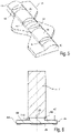
- the 6 shows a further embodiment of a bearing segment 24 with exactly one tooth 7 mounted on the bearing segment 24, which is held by an alternative embodiment of a retaining ring 140.
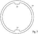
- the retaining ring 140 is in the 7 shown again in a plan view.
- the retaining ring 140 has inwardly directed lugs 141 which support the bead 26 or its lateral flanks. The cut of the sectional view of the 6 runs through the lugs 141.
- the retaining ring 140 engages in areas other than that in the section in FIG 6 shown area around a tooth base of the tooth 7. It should be noted that the tooth 7 has a recess in the area of the tooth base for engagement with the bead 26.
- the recesses ments 45 and 47 can extend to the side edges 44, 46 of the bearing segment 24. In other embodiments, additional stops may be located in the area between bead 26 and side edges 44,46.
- the gear 1 of 1 can also with the bearing segment 24 of figures 6 and 7 operate.
Landscapes
- Engineering & Computer Science (AREA)
- General Engineering & Computer Science (AREA)
- Mechanical Engineering (AREA)
- Gears, Cams (AREA)
- Rolling Contact Bearings (AREA)
- Retarders (AREA)
- Mounting Of Bearings Or Others (AREA)
Applications Claiming Priority (1)
| Application Number | Priority Date | Filing Date | Title |
|---|---|---|---|
| DE102021111364.4A DE102021111364A1 (de) | 2021-05-03 | 2021-05-03 | Getriebe |
Publications (2)
| Publication Number | Publication Date |
|---|---|
| EP4086477A1 true EP4086477A1 (fr) | 2022-11-09 |
| EP4086477B1 EP4086477B1 (fr) | 2025-10-29 |
Family
ID=81386913
Family Applications (1)
| Application Number | Title | Priority Date | Filing Date |
|---|---|---|---|
| EP22170003.2A Active EP4086477B1 (fr) | 2021-05-03 | 2022-04-26 | Boîte de vitesses |
Country Status (6)
| Country | Link |
|---|---|
| US (1) | US12000460B2 (fr) |
| EP (1) | EP4086477B1 (fr) |
| JP (1) | JP2022172448A (fr) |
| CN (1) | CN115289196A (fr) |
| DE (1) | DE102021111364A1 (fr) |
| ES (1) | ES3059317T3 (fr) |
Cited By (2)
| Publication number | Priority date | Publication date | Assignee | Title |
|---|---|---|---|---|
| WO2024193778A1 (fr) * | 2023-03-23 | 2024-09-26 | Vestas Wind Systems A/S | Transmission destinée à une éolienne |
| EP4571144A1 (fr) * | 2023-12-14 | 2025-06-18 | Vestas Wind Systems A/S | Transmission pour une éolienne |
Families Citing this family (1)
| Publication number | Priority date | Publication date | Assignee | Title |
|---|---|---|---|---|
| CN116816896A (zh) * | 2023-07-12 | 2023-09-29 | 成都理工大学 | 一种对数螺旋线齿廓的活动齿减速器 |
Citations (3)
| Publication number | Priority date | Publication date | Assignee | Title |
|---|---|---|---|---|
| DE102007016189A1 (de) * | 2007-04-02 | 2008-10-09 | Wittenstein Ag | Getriebe |
| DE102015105523A1 (de) * | 2015-04-10 | 2016-10-13 | Wittenstein Ag | Getriebe |
| DE102015105520A1 (de) | 2015-04-10 | 2016-10-13 | Wittenstein Ag | Getriebe |
Family Cites Families (6)
| Publication number | Priority date | Publication date | Assignee | Title |
|---|---|---|---|---|
| DE102006042786B4 (de) | 2006-09-08 | 2008-09-11 | Wittenstein Ag | Hohlwellengetriebe |
| DE102012102802B4 (de) * | 2012-03-30 | 2016-07-07 | Wittenstein Ag | Getriebe |
| DE102015105524B4 (de) * | 2015-04-10 | 2024-01-18 | Wittenstein Se | Getriebe |
| DE102015105526A1 (de) * | 2015-04-10 | 2016-10-13 | Wittenstein Ag | Antrieb und Verfahren zum Betreiben eines Antriebs |
| DE102015119582A1 (de) * | 2015-11-12 | 2017-05-18 | Wittenstein Se | Getriebe |
| DE102017101565A1 (de) * | 2017-01-26 | 2018-07-26 | Wittenstein Se | Koaxialgetriebe mit positiver übersetzung |
-
2021
- 2021-05-03 DE DE102021111364.4A patent/DE102021111364A1/de active Pending
-
2022
- 2022-04-26 JP JP2022072333A patent/JP2022172448A/ja active Pending
- 2022-04-26 EP EP22170003.2A patent/EP4086477B1/fr active Active
- 2022-04-26 ES ES22170003T patent/ES3059317T3/es active Active
- 2022-04-29 CN CN202210474026.4A patent/CN115289196A/zh active Pending
- 2022-05-03 US US17/735,237 patent/US12000460B2/en active Active
Patent Citations (3)
| Publication number | Priority date | Publication date | Assignee | Title |
|---|---|---|---|---|
| DE102007016189A1 (de) * | 2007-04-02 | 2008-10-09 | Wittenstein Ag | Getriebe |
| DE102015105523A1 (de) * | 2015-04-10 | 2016-10-13 | Wittenstein Ag | Getriebe |
| DE102015105520A1 (de) | 2015-04-10 | 2016-10-13 | Wittenstein Ag | Getriebe |
Cited By (2)
| Publication number | Priority date | Publication date | Assignee | Title |
|---|---|---|---|---|
| WO2024193778A1 (fr) * | 2023-03-23 | 2024-09-26 | Vestas Wind Systems A/S | Transmission destinée à une éolienne |
| EP4571144A1 (fr) * | 2023-12-14 | 2025-06-18 | Vestas Wind Systems A/S | Transmission pour une éolienne |
Also Published As
| Publication number | Publication date |
|---|---|
| ES3059317T3 (en) | 2026-03-19 |
| US20220349457A1 (en) | 2022-11-03 |
| CN115289196A (zh) | 2022-11-04 |
| DE102021111364A1 (de) | 2022-11-03 |
| US12000460B2 (en) | 2024-06-04 |
| JP2022172448A (ja) | 2022-11-16 |
| EP4086477B1 (fr) | 2025-10-29 |
Similar Documents
| Publication | Publication Date | Title |
|---|---|---|
| EP3354934B1 (fr) | Engrenage coaxiale à traduction positive | |
| DE3738521C1 (de) | Planetengetriebe | |
| DE102012102802B4 (de) | Getriebe | |
| DE102015105524B4 (de) | Getriebe | |
| DE102015105523B4 (de) | Getriebe | |
| EP4086477B1 (fr) | Boîte de vitesses | |
| EP3168496B1 (fr) | Engrenage et methode pour produire un tel engrenage | |
| DE102010011820A1 (de) | Planetenwälzgewindetrieb | |
| EP3751174A1 (fr) | Mécanisme de réglage | |
| DE102020132794A1 (de) | Koaxialgetriebe | |
| EP3225881A1 (fr) | Transmission a reducteur harmonique | |
| DE102018130612A1 (de) | Planetenwälzgewindetrieb für eine Hinterachslenkung eines Fahrzeugs sowie Hinterachslenkungsaktuator mit einem solchen Planetenwälzgewindetrieb | |
| DE4016986A1 (de) | Linearkugellager | |
| DE102015105525B4 (de) | Schwenksegment | |
| EP2255104B1 (fr) | Boite de vitesses | |
| EP0103825A2 (fr) | Accouplement élastique | |
| EP3982005B1 (fr) | Engrenage coaxial | |
| EP3168497B1 (fr) | Engrenage et utilisation d'une engrenage | |
| DE2809221C2 (de) | Lenkgetriebe für Kraftfahrzeuge mit änderbarem Übersetztungsverhältnis | |
| EP0719964B1 (fr) | Transmission planétaire à engrenages droits | |
| EP3828444A1 (fr) | Boîte de vitesses | |
| DE102019212221A1 (de) | Wellgetriebe | |
| DE102022124121A1 (de) | Wälzlager | |
| DE102019212220A1 (de) | Wellgetriebe | |
| DE102015105522B4 (de) | Bausatz mit einem Antriebselement für ein Getriebe |
Legal Events
| Date | Code | Title | Description |
|---|---|---|---|
| PUAI | Public reference made under article 153(3) epc to a published international application that has entered the european phase |
Free format text: ORIGINAL CODE: 0009012 |
|
| STAA | Information on the status of an ep patent application or granted ep patent |
Free format text: STATUS: THE APPLICATION HAS BEEN PUBLISHED |
|
| AK | Designated contracting states |
Kind code of ref document: A1 Designated state(s): AL AT BE BG CH CY CZ DE DK EE ES FI FR GB GR HR HU IE IS IT LI LT LU LV MC MK MT NL NO PL PT RO RS SE SI SK SM TR |
|
| STAA | Information on the status of an ep patent application or granted ep patent |
Free format text: STATUS: REQUEST FOR EXAMINATION WAS MADE |
|
| 17P | Request for examination filed |
Effective date: 20221124 |
|
| RBV | Designated contracting states (corrected) |
Designated state(s): AL AT BE BG CH CY CZ DE DK EE ES FI FR GB GR HR HU IE IS IT LI LT LU LV MC MK MT NL NO PL PT RO RS SE SI SK SM TR |
|
| STAA | Information on the status of an ep patent application or granted ep patent |
Free format text: STATUS: EXAMINATION IS IN PROGRESS |
|
| 17Q | First examination report despatched |
Effective date: 20231030 |
|
| GRAP | Despatch of communication of intention to grant a patent |
Free format text: ORIGINAL CODE: EPIDOSNIGR1 |
|
| STAA | Information on the status of an ep patent application or granted ep patent |
Free format text: STATUS: GRANT OF PATENT IS INTENDED |
|
| INTG | Intention to grant announced |
Effective date: 20250526 |
|
| GRAS | Grant fee paid |
Free format text: ORIGINAL CODE: EPIDOSNIGR3 |
|
| GRAA | (expected) grant |
Free format text: ORIGINAL CODE: 0009210 |
|
| STAA | Information on the status of an ep patent application or granted ep patent |
Free format text: STATUS: THE PATENT HAS BEEN GRANTED |
|
| AK | Designated contracting states |
Kind code of ref document: B1 Designated state(s): AL AT BE BG CH CY CZ DE DK EE ES FI FR GB GR HR HU IE IS IT LI LT LU LV MC MK MT NL NO PL PT RO RS SE SI SK SM TR |
|
| REG | Reference to a national code |
Ref country code: CH Ref legal event code: F10 Free format text: ST27 STATUS EVENT CODE: U-0-0-F10-F00 (AS PROVIDED BY THE NATIONAL OFFICE) Effective date: 20251029 Ref country code: GB Ref legal event code: FG4D Free format text: NOT ENGLISH |
|
| REG | Reference to a national code |
Ref country code: CH Ref legal event code: R17 Free format text: ST27 STATUS EVENT CODE: U-0-0-R10-R17 (AS PROVIDED BY THE NATIONAL OFFICE) Effective date: 20251111 |
|
| REG | Reference to a national code |
Ref country code: IE Ref legal event code: FG4D Free format text: LANGUAGE OF EP DOCUMENT: GERMAN |
|
| REG | Reference to a national code |
Ref country code: DE Ref legal event code: R096 Ref document number: 502022005897 Country of ref document: DE |
|
| REG | Reference to a national code |
Ref country code: NL Ref legal event code: MP Effective date: 20251029 |
|
| REG | Reference to a national code |
Ref country code: ES Ref legal event code: FG2A Ref document number: 3059317 Country of ref document: ES Kind code of ref document: T3 Effective date: 20260319 |
|
| REG | Reference to a national code |
Ref country code: LT Ref legal event code: MG9D |
|
| PG25 | Lapsed in a contracting state [announced via postgrant information from national office to epo] |
Ref country code: NO Free format text: LAPSE BECAUSE OF FAILURE TO SUBMIT A TRANSLATION OF THE DESCRIPTION OR TO PAY THE FEE WITHIN THE PRESCRIBED TIME-LIMIT Effective date: 20260129 |
|
| PG25 | Lapsed in a contracting state [announced via postgrant information from national office to epo] |
Ref country code: HR Free format text: LAPSE BECAUSE OF FAILURE TO SUBMIT A TRANSLATION OF THE DESCRIPTION OR TO PAY THE FEE WITHIN THE PRESCRIBED TIME-LIMIT Effective date: 20251029 Ref country code: FI Free format text: LAPSE BECAUSE OF FAILURE TO SUBMIT A TRANSLATION OF THE DESCRIPTION OR TO PAY THE FEE WITHIN THE PRESCRIBED TIME-LIMIT Effective date: 20251029 |
|
| PG25 | Lapsed in a contracting state [announced via postgrant information from national office to epo] |
Ref country code: NL Free format text: LAPSE BECAUSE OF FAILURE TO SUBMIT A TRANSLATION OF THE DESCRIPTION OR TO PAY THE FEE WITHIN THE PRESCRIBED TIME-LIMIT Effective date: 20251029 |
|
| PG25 | Lapsed in a contracting state [announced via postgrant information from national office to epo] |
Ref country code: RS Free format text: LAPSE BECAUSE OF FAILURE TO SUBMIT A TRANSLATION OF THE DESCRIPTION OR TO PAY THE FEE WITHIN THE PRESCRIBED TIME-LIMIT Effective date: 20260129 |
|
| PG25 | Lapsed in a contracting state [announced via postgrant information from national office to epo] |
Ref country code: IS Free format text: LAPSE BECAUSE OF FAILURE TO SUBMIT A TRANSLATION OF THE DESCRIPTION OR TO PAY THE FEE WITHIN THE PRESCRIBED TIME-LIMIT Effective date: 20260228 |
|
| PG25 | Lapsed in a contracting state [announced via postgrant information from national office to epo] |
Ref country code: PT Free format text: LAPSE BECAUSE OF FAILURE TO SUBMIT A TRANSLATION OF THE DESCRIPTION OR TO PAY THE FEE WITHIN THE PRESCRIBED TIME-LIMIT Effective date: 20260302 |
|
| PG25 | Lapsed in a contracting state [announced via postgrant information from national office to epo] |
Ref country code: PL Free format text: LAPSE BECAUSE OF FAILURE TO SUBMIT A TRANSLATION OF THE DESCRIPTION OR TO PAY THE FEE WITHIN THE PRESCRIBED TIME-LIMIT Effective date: 20251029 |
|
| PG25 | Lapsed in a contracting state [announced via postgrant information from national office to epo] |
Ref country code: LV Free format text: LAPSE BECAUSE OF FAILURE TO SUBMIT A TRANSLATION OF THE DESCRIPTION OR TO PAY THE FEE WITHIN THE PRESCRIBED TIME-LIMIT Effective date: 20251029 |
|
| PG25 | Lapsed in a contracting state [announced via postgrant information from national office to epo] |
Ref country code: BG Free format text: LAPSE BECAUSE OF FAILURE TO SUBMIT A TRANSLATION OF THE DESCRIPTION OR TO PAY THE FEE WITHIN THE PRESCRIBED TIME-LIMIT Effective date: 20251029 |
|
| REG | Reference to a national code |
Ref country code: CH Ref legal event code: U11 Free format text: ST27 STATUS EVENT CODE: U-0-0-U10-U11 (AS PROVIDED BY THE NATIONAL OFFICE) Effective date: 20260501 |
|
| PG25 | Lapsed in a contracting state [announced via postgrant information from national office to epo] |
Ref country code: LT Free format text: LAPSE BECAUSE OF FAILURE TO SUBMIT A TRANSLATION OF THE DESCRIPTION OR TO PAY THE FEE WITHIN THE PRESCRIBED TIME-LIMIT Effective date: 20251029 |
|
| PG25 | Lapsed in a contracting state [announced via postgrant information from national office to epo] |
Ref country code: SM Free format text: LAPSE BECAUSE OF FAILURE TO SUBMIT A TRANSLATION OF THE DESCRIPTION OR TO PAY THE FEE WITHIN THE PRESCRIBED TIME-LIMIT Effective date: 20251029 |
|
| PGFP | Annual fee paid to national office [announced via postgrant information from national office to epo] |
Ref country code: ES Payment date: 20260615 Year of fee payment: 5 |
|
| PG25 | Lapsed in a contracting state [announced via postgrant information from national office to epo] |
Ref country code: DK Free format text: LAPSE BECAUSE OF FAILURE TO SUBMIT A TRANSLATION OF THE DESCRIPTION OR TO PAY THE FEE WITHIN THE PRESCRIBED TIME-LIMIT Effective date: 20251029 |
|
| PG25 | Lapsed in a contracting state [announced via postgrant information from national office to epo] |
Ref country code: IT Free format text: LAPSE BECAUSE OF FAILURE TO SUBMIT A TRANSLATION OF THE DESCRIPTION OR TO PAY THE FEE WITHIN THE PRESCRIBED TIME-LIMIT Effective date: 20251029 |
|
| PGFP | Annual fee paid to national office [announced via postgrant information from national office to epo] |
Ref country code: DE Payment date: 20260422 Year of fee payment: 5 |
|
| PGFP | Annual fee paid to national office [announced via postgrant information from national office to epo] |
Ref country code: AT Payment date: 20260714 Year of fee payment: 5 |
|
| PGFP | Annual fee paid to national office [announced via postgrant information from national office to epo] |
Ref country code: CH Payment date: 20260501 Year of fee payment: 5 |
|
| PG25 | Lapsed in a contracting state [announced via postgrant information from national office to epo] |
Ref country code: EE Free format text: LAPSE BECAUSE OF FAILURE TO SUBMIT A TRANSLATION OF THE DESCRIPTION OR TO PAY THE FEE WITHIN THE PRESCRIBED TIME-LIMIT Effective date: 20251029 |
|
| PG25 | Lapsed in a contracting state [announced via postgrant information from national office to epo] |
Ref country code: CZ Free format text: LAPSE BECAUSE OF FAILURE TO SUBMIT A TRANSLATION OF THE DESCRIPTION OR TO PAY THE FEE WITHIN THE PRESCRIBED TIME-LIMIT Effective date: 20251029 |
|
| PG25 | Lapsed in a contracting state [announced via postgrant information from national office to epo] |
Ref country code: SK Free format text: LAPSE BECAUSE OF FAILURE TO SUBMIT A TRANSLATION OF THE DESCRIPTION OR TO PAY THE FEE WITHIN THE PRESCRIBED TIME-LIMIT Effective date: 20251029 |
|
| PG25 | Lapsed in a contracting state [announced via postgrant information from national office to epo] |
Ref country code: SE Free format text: LAPSE BECAUSE OF FAILURE TO SUBMIT A TRANSLATION OF THE DESCRIPTION OR TO PAY THE FEE WITHIN THE PRESCRIBED TIME-LIMIT Effective date: 20251029 |