EP4086564A1 - Zündvorrichtung für eine randfeuerpatrone - Google Patents
Zündvorrichtung für eine randfeuerpatrone Download PDFInfo
- Publication number
- EP4086564A1 EP4086564A1 EP22171137.7A EP22171137A EP4086564A1 EP 4086564 A1 EP4086564 A1 EP 4086564A1 EP 22171137 A EP22171137 A EP 22171137A EP 4086564 A1 EP4086564 A1 EP 4086564A1
- Authority
- EP
- European Patent Office
- Prior art keywords
- firing
- firing pin
- ignition device
- longitudinal axis
- pins
- Prior art date
- Legal status (The legal status is an assumption and is not a legal conclusion. Google has not performed a legal analysis and makes no representation as to the accuracy of the status listed.)
- Granted
Links
Images


Classifications
-
- F—MECHANICAL ENGINEERING; LIGHTING; HEATING; WEAPONS; BLASTING
- F41—WEAPONS
- F41A—FUNCTIONAL FEATURES OR DETAILS COMMON TO BOTH SMALLARMS AND ORDNANCE, e.g. CANNONS; MOUNTINGS FOR SMALLARMS OR ORDNANCE
- F41A19/00—Firing or trigger mechanisms; Cocking mechanisms
- F41A19/06—Mechanical firing mechanisms, e.g. counterrecoil firing, recoil actuated firing mechanisms
- F41A19/13—Percussion or firing pins, i.e. fixed or slidably-mounted striker elements; Mountings therefor
Definitions
- the invention relates to an ignition device for a rimfire cartridge according to the preamble of patent claim 1.
- a primer is located in the center of the case base.
- the priming charge in rimfire cartridges is cast into the base of the case and thus into the inner circumferential groove of the hollow rim of the case protruding from the outside.
- the firing pin hits the edge of the case base from behind, it is crushed, which triggers the ignition of the primer charge located in the groove and, as a result, the ignition of the propellant charge powder in contact with it.
- the disadvantage is that ignition by crushing the edge requires a low maximum wall thickness, at least in the area of the sleeve. For these reasons, a soft material such as copper or brass with a high copper content is used to manufacture the sleeve by deep drawing. This limits the combustion pressure and thus also the maximum projectile energy.
- Another disadvantage is that once a cartridge case has been fired, it can no longer be used because the edge of the case has been irreversibly damaged by the impression of the firing pin.
- U.S. Patent No. 2,793,455 from 1954 describes a rifle with a sliding bolt which is guided in the bore of a rifle barrel.
- a breech cap threads onto the forward end of the slide bolt and slides against the rear of a rimfire cartridge.
- the locking cap is provided with three guide bores, in which three pins of a cylindrical firing pin are guided. When the trigger is released, the pins will hit the rim of the rimfire cartridge and a shot will be fired.
- U.S. Patent No. 7,143,537 from 2006 describes a firing pin assembly that includes a single firing pin and a firing pin shaft.
- the firing pin is received in a slot in the end of the firing pin shaft for retention therein with a spring retaining sleeve, a main spring and a main spring sleeve.
- the firing pin is detachable from the firing pin assembly and can be replaced to provide long term use of the firing pin assembly.
- the spring retaining sleeve is oriented to hold the components securely in place, the firing pin assembly acts as a unit.
- the present invention is now based on the object of specifying an ignition device for a rimfire cartridge which triggers reliable ignition and ensures axially stable alignment of the cartridge on the sighting axis.
- the ignition device is provided for a firearm with a rimfire cartridge and has a firing pin and a pretensioning spring, the firing pin being guided in a guide cylinder in the breech housing of the firearm.
- the firing pin is provided with a firing head, which has at least two firing pins arranged symmetrically to the longitudinal axis of the firing head.
- the guide cylinder At its front end in the direction of travel, the guide cylinder has a base plate with bores that serve to guide the firing pins.
- the free end of the firing pins is designed with an edge that is bevelled towards the longitudinal axis
- the beveled edge according to claim 2 forms an angle of 10° to 30° with respect to the perpendicular to the longitudinal axis of the firing pin.
- a setback in the angular range of 5° to 35° can be provided on each side relative to the perpendicular to the longitudinal axis of the firing pin.
- the beveled edge is provided with a flat ground back on the side facing away from the longitudinal axis.
- the concave ground-back advantageously forms an angle of 1° to 6° to the horizontal, increasing outwards.
- this firing head can be arranged in a freely swinging manner on the firing pin.
- an elastic intermediate piece can be provided between the firing head and the firing pin.
- the impact base of the guide cylinder has a circular indentation, which is used to accommodate and position the base of the rimfire ignitable cartridge.
- an ignition device 1 with a firing pin 2 a movable firing head 3 with a longitudinal axis 4 and three firing pins 5 arranged symmetrically to the longitudinal axis on the firing head 3 is shown in perspective.
- the firing head 3 is movable, in particular freely swinging, attached to the firing pin 2 in order to adjust and compensate for any dimensional tolerances of the cartridge base before the impact with the firing pin 2 takes place.
- an elastic spacer is provided between the firing head 3 and the firing pin 2 (not shown).
- a guide cylinder 6 is shown with an impact base 7 which has three bores 8 which serve to guide the firing pins 4 . Furthermore, the impact base 7 has a circular depression 9, which serves to accommodate a base of a rimfire cartridge.
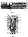
- FIG. 5 and 6 the bottom 10 of a cartridge case 11 is shown with a deep-drawn groove 12 - in figure 5 partly in cold cuts.
- An ignition mass 13 is provided in the groove 12 in the form of a ring and surrounds a propellant charge 14 .
- a firing pin 15 shown schematically, the edge 16 is suddenly crushed, whereby the ignition mass 13 is ignited by friction and then the propellant charge 14 ignites.
- figure 7 shows the firing pins 5 in a side view, the front free ends 20 of which are each provided with a beveled edge 21 .
- the beveled edge 21 is in figure 8 can be seen more precisely and forms an angle or concave clearance of 10° to 30° in relation to the perpendicular to the longitudinal axis 4 of the firing pin 5.
- Perpendicular to the beveled edge 21 there is a cutback 22 on each side in the angular range of 5° to 45° to the longitudinal axis 4 of the firing pin 5 intended.
- the beveled edge 21 is provided on the side facing away from the longitudinal axis 4 with a flat ground-back 23, which in particular forms an angle of 1° to 6° to the horizontal, increasing outwards.
- the free end 20 of the firing pin 5 can also have a different configuration. What is essential here is that at least one beveled edge 21 is provided, which points towards the fuse head 3 at an angle downwards to the longitudinal axis 4 .
- the cutbacks 22 and 23 can be omitted.
- the multiple firing of a rimfire cartridge can also be achieved with two firing pins 5, which are arranged symmetrically with respect to the longitudinal axis 4.
- four or five firing pins 5 can also be provided, with the space conditions on the firing head 3 and the diameter of the firing pins 5 limiting the maximum number of firing pins 5 .
- Three firing pins 5 are optimal, as in FIGS Figures 7 and 8 pictured.
- the multiple ignition with the ignition device according to the invention results in less environmental pollution, since the ignition mass and the gunpowder 13 burns completely. With three firing pins 5, there are no longer any malfunctions due to cold strikes, since these are eliminated by multiple firing.
- the free end 20 of the firing pin 5 can also be used, which form a beveled edge.
- the free end 20 can be square, rectangular, crescent-shaped, or circular.
Landscapes
- Engineering & Computer Science (AREA)
- General Engineering & Computer Science (AREA)
- Ignition Installations For Internal Combustion Engines (AREA)
- Portable Nailing Machines And Staplers (AREA)
Abstract
Description
- Die Erfindung betrifft eine Zündvorrichtung für eine Randfeuerpatrone nach dem Oberbegriff des Patentanspruchs 1.
- Bei den heute meist üblichen Feuerpatronen ist zentral im Hülsenboden ein Zündhütchen angeordnet. Anders als bei diesen Zentralfeuerpatronen ist der Zündsatz bei Randfeuerpatronen in den Boden der Hülse und damit in die innen umlaufende Rille des aussen überstehenden hohlen Randes der Hülse eingegossen. Durch Aufschlagen des Schlagbolzens von hinten auf den Rand des Hülsenbodens wird dieser gequetscht, was die Zündung des in der Rille befindlichen Zündsatzes und in der Folge die Zündung des damit in Kontakt stehenden Treibladungspulvers auslöst. Nachteilig ist, dass die Zündung durch Quetschung des Randes eine geringe maximale Wandstärke bedingt, zumindest im Bereich der Hülse. Aus diesen Gründen wird für die Herstellung der Hülse durch Tiefziehen ein weiches Material, wie Kupfer oder Messing mit hohem Kupfergehalt, verwendet. Der Verbrennungsdruck und somit auch die maximale Geschossenergie sind hierdurch begrenzt. Ein weiterer Nachteil ist, dass einmal abgeschossenen Patronenhülsen nicht mehr weiterverwendet werden können, weil der Hülsenrand durch den Schlagbolzenabdruck irreversibel beschädigt worden ist.
-
US Patent Nr. 2,793,455 von 1954 beschreibt ein Gewehr mit einem Schiebebolzen, welcher in der Bohrung eines Gewehrlaufs geführt ist. Eine Verschlusskappe ist auf dem vorderen Ende des Schiebbolzens aufgeschraubt und wird gegen die Rückseite einer Randfeuerpatrone geschoben. Die Verschlusskappe ist mit drei Führungsbohrungen versehen, in welcher drei Stifte eines zylindrischen Schlagbolzens geführt sind. Beim Auslösen des Abzugs werden die Stifte auf den Rand der Randfeuerpatrone aufschlagen und somit erfolgt ein Schuss. - Da die Führung der Stifte in den Führungsbohrungen sehr genau sein muss und ein genaues Auftreffen auf den Hülsenboden der Feuerpatrone nicht garantiert werden kann, hat sich die oben beschriebene Zündvorrichtung in der Praxis nicht bewährt. Um Fehlzündungen zu vermeiden, wurden beispielsweise die Henry-Gewehre, die Winchestergewehre des Models 1866, sowie die schweizerischen Vetterli-Gewehre mit einer Doppelzündung ausgerüstet, welche auf gegenüberliegende Seiten des Patronenrandes aufschlugen. Diese Doppelzündung hat sich ebenfalls nicht bewährt und findet heute keine Anwendung mehr.
- Das
US-Patent Nr. 7,143,537 von 2006 beschreibt eine Schlagbolzenanordnung, die einen einzigen Schlagbolzen und eine Schlagbolzenwelle umfasst. Der Schlagbolzen wird in einem Schlitz des Endes der Schlagbolzenwelle aufgenommen, um darin mit einer Federhaltehülse, einer Hauptfeder und einer Hauptfederhülse gehalten zu werden. Der Schlagbolzen ist von der Schlagbolzenbaugruppe abnehmbar und kann ersetzt werden, um eine langfristige Verwendung der Schlagbolzenbaugruppe zu bewirken. Wenn die Federhaltehülse so ausgerichtet ist, dass die Komponenten sicher an Ort und Stelle gehalten werden, wirkt die Schlagbolzenbaugruppe als Einheit. - Auch diese Ausführung kann Fehlzündungen nicht ausschliessen, weshalb Schützen nach Möglichkeit Zentralfeuerpatronen und mit entsprechenden Schlagbolzen ausgerüsteten Feuerwaffen verwenden anstelle von Randfeuerpatronen. Ferner wird durch den einseitigen Aufschlag des Schlagbolzens auf den Rand der Feuerpatrone eine leichte Verkantung der Patrone bewirkt, so dass kein zielgenauer Schuss erreicht werden kann. Deshalb verzichten die meisten Sportschützen auf Randfeuerpatronen, sofern reglementarisch möglich.
- Der vorliegenden Erfindung liegt nun die Aufgabe zugrunde, eine Zündvorrichtung für eine Randfeuerpatrone anzugeben, welche eine sichere Zündung auslöst und eine achsstabile Ausrichtung der Patrone auf der Zielachse gewährleistet.
- Diese Aufgabe wird durch eine Zündvorrichtung mit den Merkmalen des Patentanspruchs 1 gelöst.
- Die erfindungsgemässe Zündvorrichtung ist für eine Feuerwaffe mit einer randfeuerzündbaren Patrone vorgesehen und weist einen Schlagbolzen und einen Vorspannfeder auf, wobei der Schlagbolzen in einem Führungszylinder im Verschlussgehäuse der Feuerwaffe geführt ist. Der Schlagbolzen ist mit einem Zündkopf versehen, welcher mindestens zwei symmetrisch zur Längsachse des Zündkopfes angeordnete Zündstifte aufweist. Der Führungszylinder weist an seinem in Laufrichtung vorderen Ende einen Stossboden mit Bohrungen auf, die zur Führung der Zündstifte dient. Das freie Ende der Zündstifte ist mit einer zur Längsachse hin abgeschrägten Kante ausgebildet
- Vorteilhafterweise bildet die abgeschrägte Kante gemäss Anspruch 2 einen Winkel von 10° bis 30° gegenüber der Senkrechten zur Längsachse des Zündstiftes.
- Dabei kann mit Vorteil gemäss Anspruch 3 senkrecht zur abgeschrägten Kante je seitlich ein Rückschliff im Winkelbereich von 5° bis 35° gegenüber der Senkrechten zur Längsachse des Zündstiftes vorgesehen sein.
- In einer vorteilhaften Ausführung der Zündvorrichtung gemäss Anspruch 4 ist die abgeschrägte Kante auf der von der Längsachse abgewandten Seite mit einem flachen Rückschliff versehen. Gemäss Anspruch 5 bildet der konkave Rückschliff vorteilhafterweise einen Winkel von 1° bis 6° zur Horizontalen nach aussen aufsteigend.
- Es hat sich ferner gemäss Anspruch 6 bewährt, den Schlagbolzen mit einem beweglichen Zündkopf zu versehen, um allfällige Hülsenbodentoleranzen auszugleichen. Gemäss Anspruch 7 kann dieser Zündkopf freischwingend auf dem Schlagbolzen angeordnet sein.
- Dazu kann gemäss Anspruch 8 zwischen dem Zündkopf und dem Schlagbolzen ein elastisches Zwischenstück vorgesehen sein.
- In einer vorteilhaften Ausführung der Zündvorrichtung gemäss Anspruch 9 weist der Stossboden des Führungszylinders eine kreisrunde Vertiefung auf, welche zur Aufnahme und Positionierung des Bodens der randfeuerzündbaren Patrone dient.
- Weitere Vorteile der Erfindung ergeben sich aus den abhängigen Patentansprüchen und aus der nachfolgenden Beschreibung, in welcher die Erfindung anhand eines in den schematischen Zeichnungen dargestellten Ausführungsbeispieles näher erläutert wird. Es zeigt:
- Fig. 1
- eine Zündvorrichtung mit einem Schlagbolzen, einem beweglichen Zündkopf und drei vorstehenden Zündstiften in perspektivischer Darstellung,
- Fig. 2
- einen Führungszylinder mit einem Stossboden mit Bohrungen in perspektivischer Darstellung,
- Fig. 3
- die Zündvorrichtung der
Figur 1 in Seitenanschicht, - Fig. 4
- der Führungszylinder der
Figur 2 in Seitenansicht, - Fig. 5
- eine schematische Darstellung zur Verdeutlichung der Randfeuerzündung, vor der Auslösung, und
- Fig. 6
- dieselbe Darstellung nach dem Stoss und der Zündung,
- Fig. 7
- eine Seitenansicht der Zündstifte in perspektivischer Darstellung, und
- Fig. 8
- eine Draufsicht der Zündstifte in perspektivischer Darstellung
- In den
Figuren 1 und 3 ist eine Zündvorrichtung 1 mit einem Schlagbolzen 2, einem beweglichen Zündkopf 3 mit einer Längsachse 4 und drei symmetrisch zur Längsachse auf dem Zündkopf 3 angeordneten Zündstifte 5 perspektivisch dargestellt. Der Zündkopf 3 ist beweglich, insbesondere freischwingend, am Schlagbolzen 2 befestigt, um allfällige Masstoleranzen des Patronenbodens zu justieren und auszugleichen, bevor der Schlag mit dem Schlagbolzen 2 erfolgt. Dazu ist zwischen dem Zündkopf 3 und dem Schlagbolzen 2 ein elastisches Zwischenstück vorgesehen (nicht dargestellt). - In den
Figuren 2 und 4 ist ein Führungszylinder 6 mit einem Stossboden 7 dargestellt, welche drei Bohrungen 8 aufweist, welche zur Führung der Zündstifte 4 dienen. Ferner weist der Stossboden 7 eine kreisrunde Vertiefung 9 auf, welche zur Aufnahme eines Bodens einer randfeuerzündbaren Patrone dient. - In den
Figuren 5 und 6 ist der Boden 10 einer Patronenhülse 11 mit einer tiefgezogenen Rille 12 dargestellt - inFigur 5 teilweise in Aufschnitt. In der Rille 12 ist ringförmig eine Zündmasse 13 vorgesehen, welche eine Treibladung 14 umgibt. Mit einem schematisch dargestellten Schlagbolzen 15 wird der Rand 16 schlagartig gequetscht, wodurch die Zündmasse 13 sich durch Reibung entzündet und sodann die Treibladung 14 zündet. -
Figur 7 zeigt die Zündstifte 5 in Seitenansicht, wobei deren vorderen freien Enden 20 je mit einer abgeschrägten Kante 21 versehen ist. Die abgeschrägte Kante 21 ist inFigur 8 genauer ersichtlich und bildet einen Winkel oder konkave Freistellung von 10° bis 30° gegenüber der Senkrechten zur Längsachse 4 des Zündstiftes 5. Senkrecht zur abgeschrägten Kante 21 ist je seitlich einen Rückschliff 22 im Winkelbereich von 5° bis 45° zur Längsachse 4 des Zündstiftes 5 vorgesehen. Ferner ist die abgeschrägte Kante 21 auf der von der Längsachse 4 abgewandten Seite mit einem flachen Rückschliff 23 versehen, welcher insbesondere einen Winkel von 1° bis 6° zur Horizontalen nach aussen aufsteigend bildet. - Es versteht sich für den Fachmann, dass das freie Ende 20 des Zündstifts 5 auch eine andere Ausgestaltung haben kann. Wesentlich dabei ist, dass mindestens eine abgeschrägte Kante 21 vorgesehen ist, welche zum Zündkopf 3 hin mit einem Winkel nach unten zur Längsachse 4 zeigt. Die Rückschliffe 22 und 23 können dabei weggelassen werden.
- Die Mehrfachzündung einer Randfeuerpatrone kann auch schon erreicht werden mit zwei Zündstiften 5, welche symmetrisch gegenüber der Längsachse 4 angeordnet sind. Anderseits können auch vier oder fünft Zündstifte 5 vorgesehen sein, wobei die Platzverhältnisse auf dem Zündkopf 3 und die Durchmesser der Zündstifte 5 die maximale Anzahl Zündstifte 5 einschränkt. Optimal sind drei Zündstifte 5, wie in den
Figuren 7 und 8 abgebildet. - Durch die Mehrfachzündung mit der erfindungsgemässen Zündvorrichtung ergibt sich eine geringere Umweltbelastung, da die Zündmasse und das Schiesspulver 13 vollständig verbrennt. Es gibt mit drei Zündstiften 5 auch keine Funktionsstörung durch Kaltschläge mehr, da diese durch die Mehrfachzündung eliminiert werden.
- Es können auch andere Formen des freien Endes 20 des Zündstiftes 5 eingesetzt werden, welche eine abgeschrägte Kante bilden. Beispielsweise kann das freie Ende 20 quadratisch, rechteckig, halbmondförmig oder kreisrund ausgebildet sein.
Claims (9)
- Zündvorrichtung (1) für eine Feuerwaffe mit einer randfeuerzündbaren Patrone, welche einen Schlagbolzen (2) und einen Vorspannfeder aufweist, wobei der Schlagbolzen (2) in einem Führungszylinder (6) im Verschlussgehäuse der Feuerwaffe geführt ist, wobei der Schlagbolzen (2) mit einem Zündkopf (3) versehen ist, welcher mindestens zwei symmetrisch zur Längsachse (4) des Zündkopfes angeordnete Zündstifte (5) aufweist, und der Führungszylinder (6) an seinem in Laufrichtung vorderen Ende einen Stossboden (7) mit Bohrungen (8) aufweist, die zur Führung der Zündstifte dient, dadurch gekennzeichnet, dass das freie Ende (20) der Zündstifte (5) mit einer zur Längsachse hin abgeschrägten Kante (21) ausgebildet ist.
- Zündvorrichtung nach Anspruch 1, dadurch gekennzeichnet, dass die abgeschrägte Kante (21) einen Winkel von 10° bis 30° gegenüber der Senkrechten zur Längsachse (4) des Zündstiftes (5) bildet.
- Zündvorrichtung nach Anspruch 2, dadurch gekennzeichnet, dass senkrecht zur abgeschrägten Kante (21) je seitlich ein Rückschliff (22) im Winkelbereich von 5° bis 35° gegenüber der Senkrechten zur Längsachse (4) des Zündstiftes (5) vorgesehen ist.
- Zündvorrichtung nach Anspruch 2 oder 3, dadurch gekennzeichnet, dass die abgeschrägte Kante (21) auf der von der Längsachse (4) abgewandten Seite mit einem konkaven Rückschliff (23) versehen ist.
- Zündvorrichtung nach Anspruch 4, dadurch gekennzeichnet, dass der konkave Rückschliff (23) einen Winkel von 1° bis 6° zur Horizontalen nach aussen aufsteigend bildet.
- Zündvorrichtung nach einem der Ansprüche 1 bis 5, dadurch gekennzeichnet, dass der Schlagbolzen (2) mit einem beweglichen Zündkopf (3) versehen ist.
- Zündvorrichtung nach Anspruch 6, dadurch gekennzeichnet, dass der Zündkopf (3) freischwingend auf dem Schlagbolzen (2) angeordnet ist.
- Zündvorrichtung nach Anspruch 7, dadurch gekennzeichnet, dass zwischen dem Zündkopf (3) und dem Schlagbolzen (2) ein elastischer Ring vorgesehen ist.
- Zündvorrichtung nach einem der Ansprüche 1 bis 8, dadurch gekennzeichnet, dass der Stossboden (7) des Führungszylinders (6) eine kreisrunde Vertiefung (9) aufweist, welche zur Aufnahme des Bodens der randfeuerzündbaren Patrone dient.
Applications Claiming Priority (1)
| Application Number | Priority Date | Filing Date | Title |
|---|---|---|---|
| CH4952021 | 2021-05-04 |
Publications (3)
| Publication Number | Publication Date |
|---|---|
| EP4086564A1 true EP4086564A1 (de) | 2022-11-09 |
| EP4086564C0 EP4086564C0 (de) | 2024-01-31 |
| EP4086564B1 EP4086564B1 (de) | 2024-01-31 |
Family
ID=81579625
Family Applications (1)
| Application Number | Title | Priority Date | Filing Date |
|---|---|---|---|
| EP22171137.7A Active EP4086564B1 (de) | 2021-05-04 | 2022-05-02 | Zündvorrichtung für eine randfeuerpatrone |
Country Status (1)
| Country | Link |
|---|---|
| EP (1) | EP4086564B1 (de) |
Citations (3)
| Publication number | Priority date | Publication date | Assignee | Title |
|---|---|---|---|---|
| US2793455A (en) | 1954-12-06 | 1957-05-28 | Melvin C Wignall | Firing pin for firearms |
| US2952934A (en) * | 1956-02-14 | 1960-09-20 | Yovanovitch Lazare | Firearm with rearward swinging breech block |
| US7143537B2 (en) | 2003-11-19 | 2006-12-05 | Ra Brands, L.L.C. | Firing pin assembly |
-
2022
- 2022-05-02 EP EP22171137.7A patent/EP4086564B1/de active Active
Patent Citations (4)
| Publication number | Priority date | Publication date | Assignee | Title |
|---|---|---|---|---|
| US2793455A (en) | 1954-12-06 | 1957-05-28 | Melvin C Wignall | Firing pin for firearms |
| US2952934A (en) * | 1956-02-14 | 1960-09-20 | Yovanovitch Lazare | Firearm with rearward swinging breech block |
| US7143537B2 (en) | 2003-11-19 | 2006-12-05 | Ra Brands, L.L.C. | Firing pin assembly |
| US7516570B2 (en) * | 2003-11-19 | 2009-04-14 | Ra Brands, L.L.C. | Firing pin assembly |
Also Published As
| Publication number | Publication date |
|---|---|
| EP4086564C0 (de) | 2024-01-31 |
| EP4086564B1 (de) | 2024-01-31 |
Similar Documents
| Publication | Publication Date | Title |
|---|---|---|
| DE60107927T2 (de) | Besonders ausgebildete Waffenrohre für Übungszwecke und Platzpatronen | |
| DE1578457B2 (de) | Sicherungseinrichtung fuer aufschlagzuender | |
| DE1703205A1 (de) | Schusswaffe mit Geschoss | |
| DE19754330C1 (de) | Unterkalibriges Flintenlaufgeschoß, insbesondere für Flinten mit teilweise oder ganz gezogenem Lauf | |
| DE2747932A1 (de) | Geschosspatrone | |
| EP4086564B1 (de) | Zündvorrichtung für eine randfeuerpatrone | |
| DE2309617C2 (de) | Automatische Feuer- und Verteidigungswaffe in Form einer Pistole | |
| DE3408476A1 (de) | Vollkalibriges uebungsgeschoss | |
| DE4134505A1 (de) | Patrone zur schusssimulation mit laserstrahl | |
| DE687242C (de) | Von einem Stock abzuschiessende Stielhandgranate | |
| EP1544569B1 (de) | Schusswaffe für verformbare Geschosse, insbesondere für Gummi-Geschosse | |
| DE1728019A1 (de) | Munition zum Zuenden einer ueblichen Patrone fuer die geschlossene Kammerbauart in einem Verschluss der Bauart mit offener Kammer | |
| DE2752844A1 (de) | Mit unterschiedlichen schussweiten durch veraenderung der treibladung verschiessbarer gefechtskopf | |
| DE69806317T2 (de) | Faustfeuerwaffe für Unschädlichmachungsgeschosse | |
| DE102018008106A1 (de) | Führungsbandanordnung, Geschoss und Bewaffnung | |
| DE1428677A1 (de) | Zuendausloesevorrichtung fuer Moerser-UEbungsmunition | |
| DE2856859A1 (de) | Uebungsflugkoerper mit drallstabilisierung | |
| DE2907612C2 (de) | ||
| EP4715314A1 (de) | Codierungs-sicherungssystem für feuerwaffen | |
| DE1122876B (de) | Fuer rueckstossfreie leichte Geschuetze bestimmte Lehrpatrone | |
| CH681566A5 (en) | Insert for weapon firing small calibre ammunition - comprises barrel and loading casing with ratio between inner and outer dia. of barrel amounting to more than 0.6 with inner dia. of less than 5 mm | |
| EP1451520B1 (de) | Übungspatrone | |
| DE197304C (de) | ||
| CH218108A (de) | Einsatzgranate für Geschütze zum Schiessen mit Munition kleineren Kalibers. | |
| DE3400222A1 (de) | Spielzeugwaffe |
Legal Events
| Date | Code | Title | Description |
|---|---|---|---|
| PUAI | Public reference made under article 153(3) epc to a published international application that has entered the european phase |
Free format text: ORIGINAL CODE: 0009012 |
|
| STAA | Information on the status of an ep patent application or granted ep patent |
Free format text: STATUS: THE APPLICATION HAS BEEN PUBLISHED |
|
| AK | Designated contracting states |
Kind code of ref document: A1 Designated state(s): AL AT BE BG CH CY CZ DE DK EE ES FI FR GB GR HR HU IE IS IT LI LT LU LV MC MK MT NL NO PL PT RO RS SE SI SK SM TR |
|
| STAA | Information on the status of an ep patent application or granted ep patent |
Free format text: STATUS: REQUEST FOR EXAMINATION WAS MADE |
|
| 17P | Request for examination filed |
Effective date: 20230309 |
|
| RBV | Designated contracting states (corrected) |
Designated state(s): AL AT BE BG CH CY CZ DE DK EE ES FI FR GB GR HR HU IE IS IT LI LT LU LV MC MK MT NL NO PL PT RO RS SE SI SK SM TR |
|
| GRAP | Despatch of communication of intention to grant a patent |
Free format text: ORIGINAL CODE: EPIDOSNIGR1 |
|
| STAA | Information on the status of an ep patent application or granted ep patent |
Free format text: STATUS: GRANT OF PATENT IS INTENDED |
|
| INTG | Intention to grant announced |
Effective date: 20231030 |
|
| GRAS | Grant fee paid |
Free format text: ORIGINAL CODE: EPIDOSNIGR3 |
|
| GRAA | (expected) grant |
Free format text: ORIGINAL CODE: 0009210 |
|
| STAA | Information on the status of an ep patent application or granted ep patent |
Free format text: STATUS: THE PATENT HAS BEEN GRANTED |
|
| AK | Designated contracting states |
Kind code of ref document: B1 Designated state(s): AL AT BE BG CH CY CZ DE DK EE ES FI FR GB GR HR HU IE IS IT LI LT LU LV MC MK MT NL NO PL PT RO RS SE SI SK SM TR |
|
| REG | Reference to a national code |
Ref country code: GB Ref legal event code: FG4D Free format text: NOT ENGLISH Ref country code: CH Ref legal event code: EP |
|
| REG | Reference to a national code |
Ref country code: DE Ref legal event code: R096 Ref document number: 502022000452 Country of ref document: DE |
|
| REG | Reference to a national code |
Ref country code: IE Ref legal event code: FG4D Free format text: LANGUAGE OF EP DOCUMENT: GERMAN |
|
| U01 | Request for unitary effect filed |
Effective date: 20240201 |
|
| U07 | Unitary effect registered |
Designated state(s): AT BE BG DE DK EE FI FR IT LT LU LV MT NL PT SE SI Effective date: 20240212 |
|
| U20 | Renewal fee for the european patent with unitary effect paid |
Year of fee payment: 3 Effective date: 20240508 |
|
| PG25 | Lapsed in a contracting state [announced via postgrant information from national office to epo] |
Ref country code: IS Free format text: LAPSE BECAUSE OF FAILURE TO SUBMIT A TRANSLATION OF THE DESCRIPTION OR TO PAY THE FEE WITHIN THE PRESCRIBED TIME-LIMIT Effective date: 20240531 |
|
| PG25 | Lapsed in a contracting state [announced via postgrant information from national office to epo] |
Ref country code: GR Free format text: LAPSE BECAUSE OF FAILURE TO SUBMIT A TRANSLATION OF THE DESCRIPTION OR TO PAY THE FEE WITHIN THE PRESCRIBED TIME-LIMIT Effective date: 20240501 |
|
| PG25 | Lapsed in a contracting state [announced via postgrant information from national office to epo] |
Ref country code: RS Free format text: LAPSE BECAUSE OF FAILURE TO SUBMIT A TRANSLATION OF THE DESCRIPTION OR TO PAY THE FEE WITHIN THE PRESCRIBED TIME-LIMIT Effective date: 20240430 Ref country code: HR Free format text: LAPSE BECAUSE OF FAILURE TO SUBMIT A TRANSLATION OF THE DESCRIPTION OR TO PAY THE FEE WITHIN THE PRESCRIBED TIME-LIMIT Effective date: 20240131 |
|
| PG25 | Lapsed in a contracting state [announced via postgrant information from national office to epo] |
Ref country code: ES Free format text: LAPSE BECAUSE OF FAILURE TO SUBMIT A TRANSLATION OF THE DESCRIPTION OR TO PAY THE FEE WITHIN THE PRESCRIBED TIME-LIMIT Effective date: 20240131 |
|
| PG25 | Lapsed in a contracting state [announced via postgrant information from national office to epo] |
Ref country code: RS Free format text: LAPSE BECAUSE OF FAILURE TO SUBMIT A TRANSLATION OF THE DESCRIPTION OR TO PAY THE FEE WITHIN THE PRESCRIBED TIME-LIMIT Effective date: 20240430 Ref country code: NO Free format text: LAPSE BECAUSE OF FAILURE TO SUBMIT A TRANSLATION OF THE DESCRIPTION OR TO PAY THE FEE WITHIN THE PRESCRIBED TIME-LIMIT Effective date: 20240430 Ref country code: IS Free format text: LAPSE BECAUSE OF FAILURE TO SUBMIT A TRANSLATION OF THE DESCRIPTION OR TO PAY THE FEE WITHIN THE PRESCRIBED TIME-LIMIT Effective date: 20240531 Ref country code: HR Free format text: LAPSE BECAUSE OF FAILURE TO SUBMIT A TRANSLATION OF THE DESCRIPTION OR TO PAY THE FEE WITHIN THE PRESCRIBED TIME-LIMIT Effective date: 20240131 Ref country code: GR Free format text: LAPSE BECAUSE OF FAILURE TO SUBMIT A TRANSLATION OF THE DESCRIPTION OR TO PAY THE FEE WITHIN THE PRESCRIBED TIME-LIMIT Effective date: 20240501 Ref country code: ES Free format text: LAPSE BECAUSE OF FAILURE TO SUBMIT A TRANSLATION OF THE DESCRIPTION OR TO PAY THE FEE WITHIN THE PRESCRIBED TIME-LIMIT Effective date: 20240131 |
|
| PG25 | Lapsed in a contracting state [announced via postgrant information from national office to epo] |
Ref country code: PL Free format text: LAPSE BECAUSE OF FAILURE TO SUBMIT A TRANSLATION OF THE DESCRIPTION OR TO PAY THE FEE WITHIN THE PRESCRIBED TIME-LIMIT Effective date: 20240131 |
|
| PG25 | Lapsed in a contracting state [announced via postgrant information from national office to epo] |
Ref country code: PL Free format text: LAPSE BECAUSE OF FAILURE TO SUBMIT A TRANSLATION OF THE DESCRIPTION OR TO PAY THE FEE WITHIN THE PRESCRIBED TIME-LIMIT Effective date: 20240131 |
|
| PG25 | Lapsed in a contracting state [announced via postgrant information from national office to epo] |
Ref country code: SM Free format text: LAPSE BECAUSE OF FAILURE TO SUBMIT A TRANSLATION OF THE DESCRIPTION OR TO PAY THE FEE WITHIN THE PRESCRIBED TIME-LIMIT Effective date: 20240131 |
|
| PG25 | Lapsed in a contracting state [announced via postgrant information from national office to epo] |
Ref country code: CZ Free format text: LAPSE BECAUSE OF FAILURE TO SUBMIT A TRANSLATION OF THE DESCRIPTION OR TO PAY THE FEE WITHIN THE PRESCRIBED TIME-LIMIT Effective date: 20240131 |
|
| PG25 | Lapsed in a contracting state [announced via postgrant information from national office to epo] |
Ref country code: SK Free format text: LAPSE BECAUSE OF FAILURE TO SUBMIT A TRANSLATION OF THE DESCRIPTION OR TO PAY THE FEE WITHIN THE PRESCRIBED TIME-LIMIT Effective date: 20240131 |
|
| PG25 | Lapsed in a contracting state [announced via postgrant information from national office to epo] |
Ref country code: SM Free format text: LAPSE BECAUSE OF FAILURE TO SUBMIT A TRANSLATION OF THE DESCRIPTION OR TO PAY THE FEE WITHIN THE PRESCRIBED TIME-LIMIT Effective date: 20240131 Ref country code: SK Free format text: LAPSE BECAUSE OF FAILURE TO SUBMIT A TRANSLATION OF THE DESCRIPTION OR TO PAY THE FEE WITHIN THE PRESCRIBED TIME-LIMIT Effective date: 20240131 Ref country code: RO Free format text: LAPSE BECAUSE OF FAILURE TO SUBMIT A TRANSLATION OF THE DESCRIPTION OR TO PAY THE FEE WITHIN THE PRESCRIBED TIME-LIMIT Effective date: 20240131 Ref country code: CZ Free format text: LAPSE BECAUSE OF FAILURE TO SUBMIT A TRANSLATION OF THE DESCRIPTION OR TO PAY THE FEE WITHIN THE PRESCRIBED TIME-LIMIT Effective date: 20240131 |
|
| REG | Reference to a national code |
Ref country code: DE Ref legal event code: R097 Ref document number: 502022000452 Country of ref document: DE |
|
| PLBE | No opposition filed within time limit |
Free format text: ORIGINAL CODE: 0009261 |
|
| STAA | Information on the status of an ep patent application or granted ep patent |
Free format text: STATUS: NO OPPOSITION FILED WITHIN TIME LIMIT |
|
| 26N | No opposition filed |
Effective date: 20241101 |
|
| PG25 | Lapsed in a contracting state [announced via postgrant information from national office to epo] |
Ref country code: MC Free format text: LAPSE BECAUSE OF FAILURE TO SUBMIT A TRANSLATION OF THE DESCRIPTION OR TO PAY THE FEE WITHIN THE PRESCRIBED TIME-LIMIT Effective date: 20240131 |
|
| PG25 | Lapsed in a contracting state [announced via postgrant information from national office to epo] |
Ref country code: MC Free format text: LAPSE BECAUSE OF FAILURE TO SUBMIT A TRANSLATION OF THE DESCRIPTION OR TO PAY THE FEE WITHIN THE PRESCRIBED TIME-LIMIT Effective date: 20240131 |
|
| PG25 | Lapsed in a contracting state [announced via postgrant information from national office to epo] |
Ref country code: IE Free format text: LAPSE BECAUSE OF NON-PAYMENT OF DUE FEES Effective date: 20240502 |
|
| U20 | Renewal fee for the european patent with unitary effect paid |
Year of fee payment: 4 Effective date: 20250509 |
|
| PGFP | Annual fee paid to national office [announced via postgrant information from national office to epo] |
Ref country code: CH Payment date: 20250601 Year of fee payment: 4 |
|
| PG25 | Lapsed in a contracting state [announced via postgrant information from national office to epo] |
Ref country code: CY Free format text: LAPSE BECAUSE OF FAILURE TO SUBMIT A TRANSLATION OF THE DESCRIPTION OR TO PAY THE FEE WITHIN THE PRESCRIBED TIME-LIMIT; INVALID AB INITIO Effective date: 20220502 |
|
| PG25 | Lapsed in a contracting state [announced via postgrant information from national office to epo] |
Ref country code: HU Free format text: LAPSE BECAUSE OF FAILURE TO SUBMIT A TRANSLATION OF THE DESCRIPTION OR TO PAY THE FEE WITHIN THE PRESCRIBED TIME-LIMIT; INVALID AB INITIO Effective date: 20220502 |