EP4086564A1 - Dispositif de mise à feu pour une cartouche à percussion annulaire - Google Patents
Dispositif de mise à feu pour une cartouche à percussion annulaire Download PDFInfo
- Publication number
- EP4086564A1 EP4086564A1 EP22171137.7A EP22171137A EP4086564A1 EP 4086564 A1 EP4086564 A1 EP 4086564A1 EP 22171137 A EP22171137 A EP 22171137A EP 4086564 A1 EP4086564 A1 EP 4086564A1
- Authority
- EP
- European Patent Office
- Prior art keywords
- firing
- firing pin
- ignition device
- longitudinal axis
- pins
- Prior art date
- Legal status (The legal status is an assumption and is not a legal conclusion. Google has not performed a legal analysis and makes no representation as to the accuracy of the status listed.)
- Granted
Links
Images


Classifications
-
- F—MECHANICAL ENGINEERING; LIGHTING; HEATING; WEAPONS; BLASTING
- F41—WEAPONS
- F41A—FUNCTIONAL FEATURES OR DETAILS COMMON TO BOTH SMALLARMS AND ORDNANCE, e.g. CANNONS; MOUNTINGS FOR SMALLARMS OR ORDNANCE
- F41A19/00—Firing or trigger mechanisms; Cocking mechanisms
- F41A19/06—Mechanical firing mechanisms, e.g. counterrecoil firing, recoil actuated firing mechanisms
- F41A19/13—Percussion or firing pins, i.e. fixed or slidably-mounted striker elements; Mountings therefor
Definitions
- the invention relates to an ignition device for a rimfire cartridge according to the preamble of patent claim 1.
- a primer is located in the center of the case base.
- the priming charge in rimfire cartridges is cast into the base of the case and thus into the inner circumferential groove of the hollow rim of the case protruding from the outside.
- the firing pin hits the edge of the case base from behind, it is crushed, which triggers the ignition of the primer charge located in the groove and, as a result, the ignition of the propellant charge powder in contact with it.
- the disadvantage is that ignition by crushing the edge requires a low maximum wall thickness, at least in the area of the sleeve. For these reasons, a soft material such as copper or brass with a high copper content is used to manufacture the sleeve by deep drawing. This limits the combustion pressure and thus also the maximum projectile energy.
- Another disadvantage is that once a cartridge case has been fired, it can no longer be used because the edge of the case has been irreversibly damaged by the impression of the firing pin.
- U.S. Patent No. 2,793,455 from 1954 describes a rifle with a sliding bolt which is guided in the bore of a rifle barrel.
- a breech cap threads onto the forward end of the slide bolt and slides against the rear of a rimfire cartridge.
- the locking cap is provided with three guide bores, in which three pins of a cylindrical firing pin are guided. When the trigger is released, the pins will hit the rim of the rimfire cartridge and a shot will be fired.
- U.S. Patent No. 7,143,537 from 2006 describes a firing pin assembly that includes a single firing pin and a firing pin shaft.
- the firing pin is received in a slot in the end of the firing pin shaft for retention therein with a spring retaining sleeve, a main spring and a main spring sleeve.
- the firing pin is detachable from the firing pin assembly and can be replaced to provide long term use of the firing pin assembly.
- the spring retaining sleeve is oriented to hold the components securely in place, the firing pin assembly acts as a unit.
- the present invention is now based on the object of specifying an ignition device for a rimfire cartridge which triggers reliable ignition and ensures axially stable alignment of the cartridge on the sighting axis.
- the ignition device is provided for a firearm with a rimfire cartridge and has a firing pin and a pretensioning spring, the firing pin being guided in a guide cylinder in the breech housing of the firearm.
- the firing pin is provided with a firing head, which has at least two firing pins arranged symmetrically to the longitudinal axis of the firing head.
- the guide cylinder At its front end in the direction of travel, the guide cylinder has a base plate with bores that serve to guide the firing pins.
- the free end of the firing pins is designed with an edge that is bevelled towards the longitudinal axis
- the beveled edge according to claim 2 forms an angle of 10° to 30° with respect to the perpendicular to the longitudinal axis of the firing pin.
- a setback in the angular range of 5° to 35° can be provided on each side relative to the perpendicular to the longitudinal axis of the firing pin.
- the beveled edge is provided with a flat ground back on the side facing away from the longitudinal axis.
- the concave ground-back advantageously forms an angle of 1° to 6° to the horizontal, increasing outwards.
- this firing head can be arranged in a freely swinging manner on the firing pin.
- an elastic intermediate piece can be provided between the firing head and the firing pin.
- the impact base of the guide cylinder has a circular indentation, which is used to accommodate and position the base of the rimfire ignitable cartridge.
- an ignition device 1 with a firing pin 2 a movable firing head 3 with a longitudinal axis 4 and three firing pins 5 arranged symmetrically to the longitudinal axis on the firing head 3 is shown in perspective.
- the firing head 3 is movable, in particular freely swinging, attached to the firing pin 2 in order to adjust and compensate for any dimensional tolerances of the cartridge base before the impact with the firing pin 2 takes place.
- an elastic spacer is provided between the firing head 3 and the firing pin 2 (not shown).
- a guide cylinder 6 is shown with an impact base 7 which has three bores 8 which serve to guide the firing pins 4 . Furthermore, the impact base 7 has a circular depression 9, which serves to accommodate a base of a rimfire cartridge.
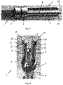
- FIG. 5 and 6 the bottom 10 of a cartridge case 11 is shown with a deep-drawn groove 12 - in figure 5 partly in cold cuts.
- An ignition mass 13 is provided in the groove 12 in the form of a ring and surrounds a propellant charge 14 .
- a firing pin 15 shown schematically, the edge 16 is suddenly crushed, whereby the ignition mass 13 is ignited by friction and then the propellant charge 14 ignites.
- figure 7 shows the firing pins 5 in a side view, the front free ends 20 of which are each provided with a beveled edge 21 .
- the beveled edge 21 is in figure 8 can be seen more precisely and forms an angle or concave clearance of 10° to 30° in relation to the perpendicular to the longitudinal axis 4 of the firing pin 5.
- Perpendicular to the beveled edge 21 there is a cutback 22 on each side in the angular range of 5° to 45° to the longitudinal axis 4 of the firing pin 5 intended.
- the beveled edge 21 is provided on the side facing away from the longitudinal axis 4 with a flat ground-back 23, which in particular forms an angle of 1° to 6° to the horizontal, increasing outwards.
- the free end 20 of the firing pin 5 can also have a different configuration. What is essential here is that at least one beveled edge 21 is provided, which points towards the fuse head 3 at an angle downwards to the longitudinal axis 4 .
- the cutbacks 22 and 23 can be omitted.
- the multiple firing of a rimfire cartridge can also be achieved with two firing pins 5, which are arranged symmetrically with respect to the longitudinal axis 4.
- four or five firing pins 5 can also be provided, with the space conditions on the firing head 3 and the diameter of the firing pins 5 limiting the maximum number of firing pins 5 .
- Three firing pins 5 are optimal, as in FIGS Figures 7 and 8 pictured.
- the multiple ignition with the ignition device according to the invention results in less environmental pollution, since the ignition mass and the gunpowder 13 burns completely. With three firing pins 5, there are no longer any malfunctions due to cold strikes, since these are eliminated by multiple firing.
- the free end 20 of the firing pin 5 can also be used, which form a beveled edge.
- the free end 20 can be square, rectangular, crescent-shaped, or circular.
Landscapes
- Engineering & Computer Science (AREA)
- General Engineering & Computer Science (AREA)
- Ignition Installations For Internal Combustion Engines (AREA)
- Portable Nailing Machines And Staplers (AREA)
Applications Claiming Priority (1)
| Application Number | Priority Date | Filing Date | Title |
|---|---|---|---|
| CH4952021 | 2021-05-04 |
Publications (3)
| Publication Number | Publication Date |
|---|---|
| EP4086564A1 true EP4086564A1 (fr) | 2022-11-09 |
| EP4086564C0 EP4086564C0 (fr) | 2024-01-31 |
| EP4086564B1 EP4086564B1 (fr) | 2024-01-31 |
Family
ID=81579625
Family Applications (1)
| Application Number | Title | Priority Date | Filing Date |
|---|---|---|---|
| EP22171137.7A Active EP4086564B1 (fr) | 2021-05-04 | 2022-05-02 | Dispositif de mise à feu pour une cartouche à percussion annulaire |
Country Status (1)
| Country | Link |
|---|---|
| EP (1) | EP4086564B1 (fr) |
Citations (3)
| Publication number | Priority date | Publication date | Assignee | Title |
|---|---|---|---|---|
| US2793455A (en) | 1954-12-06 | 1957-05-28 | Melvin C Wignall | Firing pin for firearms |
| US2952934A (en) * | 1956-02-14 | 1960-09-20 | Yovanovitch Lazare | Firearm with rearward swinging breech block |
| US7143537B2 (en) | 2003-11-19 | 2006-12-05 | Ra Brands, L.L.C. | Firing pin assembly |
-
2022
- 2022-05-02 EP EP22171137.7A patent/EP4086564B1/fr active Active
Patent Citations (4)
| Publication number | Priority date | Publication date | Assignee | Title |
|---|---|---|---|---|
| US2793455A (en) | 1954-12-06 | 1957-05-28 | Melvin C Wignall | Firing pin for firearms |
| US2952934A (en) * | 1956-02-14 | 1960-09-20 | Yovanovitch Lazare | Firearm with rearward swinging breech block |
| US7143537B2 (en) | 2003-11-19 | 2006-12-05 | Ra Brands, L.L.C. | Firing pin assembly |
| US7516570B2 (en) * | 2003-11-19 | 2009-04-14 | Ra Brands, L.L.C. | Firing pin assembly |
Also Published As
| Publication number | Publication date |
|---|---|
| EP4086564C0 (fr) | 2024-01-31 |
| EP4086564B1 (fr) | 2024-01-31 |
Similar Documents
| Publication | Publication Date | Title |
|---|---|---|
| DE60107927T2 (de) | Besonders ausgebildete Waffenrohre für Übungszwecke und Platzpatronen | |
| DE1578457B2 (de) | Sicherungseinrichtung fuer aufschlagzuender | |
| DE1703205A1 (de) | Schusswaffe mit Geschoss | |
| DE19754330C1 (de) | Unterkalibriges Flintenlaufgeschoß, insbesondere für Flinten mit teilweise oder ganz gezogenem Lauf | |
| DE2747932A1 (de) | Geschosspatrone | |
| EP4086564B1 (fr) | Dispositif de mise à feu pour une cartouche à percussion annulaire | |
| DE2309617C2 (de) | Automatische Feuer- und Verteidigungswaffe in Form einer Pistole | |
| DE3408476A1 (de) | Vollkalibriges uebungsgeschoss | |
| DE4134505A1 (de) | Patrone zur schusssimulation mit laserstrahl | |
| DE687242C (de) | Von einem Stock abzuschiessende Stielhandgranate | |
| EP1544569B1 (fr) | Arme à feu pour tirer des projectiles déformables, en particulier des projectiles en caoutchouc | |
| DE1728019A1 (de) | Munition zum Zuenden einer ueblichen Patrone fuer die geschlossene Kammerbauart in einem Verschluss der Bauart mit offener Kammer | |
| DE2752844A1 (de) | Mit unterschiedlichen schussweiten durch veraenderung der treibladung verschiessbarer gefechtskopf | |
| DE69806317T2 (de) | Faustfeuerwaffe für Unschädlichmachungsgeschosse | |
| DE102018008106A1 (de) | Führungsbandanordnung, Geschoss und Bewaffnung | |
| DE1428677A1 (de) | Zuendausloesevorrichtung fuer Moerser-UEbungsmunition | |
| DE2856859A1 (de) | Uebungsflugkoerper mit drallstabilisierung | |
| DE2907612C2 (fr) | ||
| EP4715314A1 (fr) | Système de sécurité de codage pour armes à feu | |
| DE1122876B (de) | Fuer rueckstossfreie leichte Geschuetze bestimmte Lehrpatrone | |
| CH681566A5 (en) | Insert for weapon firing small calibre ammunition - comprises barrel and loading casing with ratio between inner and outer dia. of barrel amounting to more than 0.6 with inner dia. of less than 5 mm | |
| EP1451520B1 (fr) | Cartouche d'exercice | |
| DE197304C (fr) | ||
| CH218108A (de) | Einsatzgranate für Geschütze zum Schiessen mit Munition kleineren Kalibers. | |
| DE3400222A1 (de) | Spielzeugwaffe |
Legal Events
| Date | Code | Title | Description |
|---|---|---|---|
| PUAI | Public reference made under article 153(3) epc to a published international application that has entered the european phase |
Free format text: ORIGINAL CODE: 0009012 |
|
| STAA | Information on the status of an ep patent application or granted ep patent |
Free format text: STATUS: THE APPLICATION HAS BEEN PUBLISHED |
|
| AK | Designated contracting states |
Kind code of ref document: A1 Designated state(s): AL AT BE BG CH CY CZ DE DK EE ES FI FR GB GR HR HU IE IS IT LI LT LU LV MC MK MT NL NO PL PT RO RS SE SI SK SM TR |
|
| STAA | Information on the status of an ep patent application or granted ep patent |
Free format text: STATUS: REQUEST FOR EXAMINATION WAS MADE |
|
| 17P | Request for examination filed |
Effective date: 20230309 |
|
| RBV | Designated contracting states (corrected) |
Designated state(s): AL AT BE BG CH CY CZ DE DK EE ES FI FR GB GR HR HU IE IS IT LI LT LU LV MC MK MT NL NO PL PT RO RS SE SI SK SM TR |
|
| GRAP | Despatch of communication of intention to grant a patent |
Free format text: ORIGINAL CODE: EPIDOSNIGR1 |
|
| STAA | Information on the status of an ep patent application or granted ep patent |
Free format text: STATUS: GRANT OF PATENT IS INTENDED |
|
| INTG | Intention to grant announced |
Effective date: 20231030 |
|
| GRAS | Grant fee paid |
Free format text: ORIGINAL CODE: EPIDOSNIGR3 |
|
| GRAA | (expected) grant |
Free format text: ORIGINAL CODE: 0009210 |
|
| STAA | Information on the status of an ep patent application or granted ep patent |
Free format text: STATUS: THE PATENT HAS BEEN GRANTED |
|
| AK | Designated contracting states |
Kind code of ref document: B1 Designated state(s): AL AT BE BG CH CY CZ DE DK EE ES FI FR GB GR HR HU IE IS IT LI LT LU LV MC MK MT NL NO PL PT RO RS SE SI SK SM TR |
|
| REG | Reference to a national code |
Ref country code: GB Ref legal event code: FG4D Free format text: NOT ENGLISH Ref country code: CH Ref legal event code: EP |
|
| REG | Reference to a national code |
Ref country code: DE Ref legal event code: R096 Ref document number: 502022000452 Country of ref document: DE |
|
| REG | Reference to a national code |
Ref country code: IE Ref legal event code: FG4D Free format text: LANGUAGE OF EP DOCUMENT: GERMAN |
|
| U01 | Request for unitary effect filed |
Effective date: 20240201 |
|
| U07 | Unitary effect registered |
Designated state(s): AT BE BG DE DK EE FI FR IT LT LU LV MT NL PT SE SI Effective date: 20240212 |
|
| U20 | Renewal fee for the european patent with unitary effect paid |
Year of fee payment: 3 Effective date: 20240508 |
|
| PG25 | Lapsed in a contracting state [announced via postgrant information from national office to epo] |
Ref country code: IS Free format text: LAPSE BECAUSE OF FAILURE TO SUBMIT A TRANSLATION OF THE DESCRIPTION OR TO PAY THE FEE WITHIN THE PRESCRIBED TIME-LIMIT Effective date: 20240531 |
|
| PG25 | Lapsed in a contracting state [announced via postgrant information from national office to epo] |
Ref country code: GR Free format text: LAPSE BECAUSE OF FAILURE TO SUBMIT A TRANSLATION OF THE DESCRIPTION OR TO PAY THE FEE WITHIN THE PRESCRIBED TIME-LIMIT Effective date: 20240501 |
|
| PG25 | Lapsed in a contracting state [announced via postgrant information from national office to epo] |
Ref country code: RS Free format text: LAPSE BECAUSE OF FAILURE TO SUBMIT A TRANSLATION OF THE DESCRIPTION OR TO PAY THE FEE WITHIN THE PRESCRIBED TIME-LIMIT Effective date: 20240430 Ref country code: HR Free format text: LAPSE BECAUSE OF FAILURE TO SUBMIT A TRANSLATION OF THE DESCRIPTION OR TO PAY THE FEE WITHIN THE PRESCRIBED TIME-LIMIT Effective date: 20240131 |
|
| PG25 | Lapsed in a contracting state [announced via postgrant information from national office to epo] |
Ref country code: ES Free format text: LAPSE BECAUSE OF FAILURE TO SUBMIT A TRANSLATION OF THE DESCRIPTION OR TO PAY THE FEE WITHIN THE PRESCRIBED TIME-LIMIT Effective date: 20240131 |
|
| PG25 | Lapsed in a contracting state [announced via postgrant information from national office to epo] |
Ref country code: RS Free format text: LAPSE BECAUSE OF FAILURE TO SUBMIT A TRANSLATION OF THE DESCRIPTION OR TO PAY THE FEE WITHIN THE PRESCRIBED TIME-LIMIT Effective date: 20240430 Ref country code: NO Free format text: LAPSE BECAUSE OF FAILURE TO SUBMIT A TRANSLATION OF THE DESCRIPTION OR TO PAY THE FEE WITHIN THE PRESCRIBED TIME-LIMIT Effective date: 20240430 Ref country code: IS Free format text: LAPSE BECAUSE OF FAILURE TO SUBMIT A TRANSLATION OF THE DESCRIPTION OR TO PAY THE FEE WITHIN THE PRESCRIBED TIME-LIMIT Effective date: 20240531 Ref country code: HR Free format text: LAPSE BECAUSE OF FAILURE TO SUBMIT A TRANSLATION OF THE DESCRIPTION OR TO PAY THE FEE WITHIN THE PRESCRIBED TIME-LIMIT Effective date: 20240131 Ref country code: GR Free format text: LAPSE BECAUSE OF FAILURE TO SUBMIT A TRANSLATION OF THE DESCRIPTION OR TO PAY THE FEE WITHIN THE PRESCRIBED TIME-LIMIT Effective date: 20240501 Ref country code: ES Free format text: LAPSE BECAUSE OF FAILURE TO SUBMIT A TRANSLATION OF THE DESCRIPTION OR TO PAY THE FEE WITHIN THE PRESCRIBED TIME-LIMIT Effective date: 20240131 |
|
| PG25 | Lapsed in a contracting state [announced via postgrant information from national office to epo] |
Ref country code: PL Free format text: LAPSE BECAUSE OF FAILURE TO SUBMIT A TRANSLATION OF THE DESCRIPTION OR TO PAY THE FEE WITHIN THE PRESCRIBED TIME-LIMIT Effective date: 20240131 |
|
| PG25 | Lapsed in a contracting state [announced via postgrant information from national office to epo] |
Ref country code: PL Free format text: LAPSE BECAUSE OF FAILURE TO SUBMIT A TRANSLATION OF THE DESCRIPTION OR TO PAY THE FEE WITHIN THE PRESCRIBED TIME-LIMIT Effective date: 20240131 |
|
| PG25 | Lapsed in a contracting state [announced via postgrant information from national office to epo] |
Ref country code: SM Free format text: LAPSE BECAUSE OF FAILURE TO SUBMIT A TRANSLATION OF THE DESCRIPTION OR TO PAY THE FEE WITHIN THE PRESCRIBED TIME-LIMIT Effective date: 20240131 |
|
| PG25 | Lapsed in a contracting state [announced via postgrant information from national office to epo] |
Ref country code: CZ Free format text: LAPSE BECAUSE OF FAILURE TO SUBMIT A TRANSLATION OF THE DESCRIPTION OR TO PAY THE FEE WITHIN THE PRESCRIBED TIME-LIMIT Effective date: 20240131 |
|
| PG25 | Lapsed in a contracting state [announced via postgrant information from national office to epo] |
Ref country code: SK Free format text: LAPSE BECAUSE OF FAILURE TO SUBMIT A TRANSLATION OF THE DESCRIPTION OR TO PAY THE FEE WITHIN THE PRESCRIBED TIME-LIMIT Effective date: 20240131 |
|
| PG25 | Lapsed in a contracting state [announced via postgrant information from national office to epo] |
Ref country code: SM Free format text: LAPSE BECAUSE OF FAILURE TO SUBMIT A TRANSLATION OF THE DESCRIPTION OR TO PAY THE FEE WITHIN THE PRESCRIBED TIME-LIMIT Effective date: 20240131 Ref country code: SK Free format text: LAPSE BECAUSE OF FAILURE TO SUBMIT A TRANSLATION OF THE DESCRIPTION OR TO PAY THE FEE WITHIN THE PRESCRIBED TIME-LIMIT Effective date: 20240131 Ref country code: RO Free format text: LAPSE BECAUSE OF FAILURE TO SUBMIT A TRANSLATION OF THE DESCRIPTION OR TO PAY THE FEE WITHIN THE PRESCRIBED TIME-LIMIT Effective date: 20240131 Ref country code: CZ Free format text: LAPSE BECAUSE OF FAILURE TO SUBMIT A TRANSLATION OF THE DESCRIPTION OR TO PAY THE FEE WITHIN THE PRESCRIBED TIME-LIMIT Effective date: 20240131 |
|
| REG | Reference to a national code |
Ref country code: DE Ref legal event code: R097 Ref document number: 502022000452 Country of ref document: DE |
|
| PLBE | No opposition filed within time limit |
Free format text: ORIGINAL CODE: 0009261 |
|
| STAA | Information on the status of an ep patent application or granted ep patent |
Free format text: STATUS: NO OPPOSITION FILED WITHIN TIME LIMIT |
|
| 26N | No opposition filed |
Effective date: 20241101 |
|
| PG25 | Lapsed in a contracting state [announced via postgrant information from national office to epo] |
Ref country code: MC Free format text: LAPSE BECAUSE OF FAILURE TO SUBMIT A TRANSLATION OF THE DESCRIPTION OR TO PAY THE FEE WITHIN THE PRESCRIBED TIME-LIMIT Effective date: 20240131 |
|
| PG25 | Lapsed in a contracting state [announced via postgrant information from national office to epo] |
Ref country code: MC Free format text: LAPSE BECAUSE OF FAILURE TO SUBMIT A TRANSLATION OF THE DESCRIPTION OR TO PAY THE FEE WITHIN THE PRESCRIBED TIME-LIMIT Effective date: 20240131 |
|
| PG25 | Lapsed in a contracting state [announced via postgrant information from national office to epo] |
Ref country code: IE Free format text: LAPSE BECAUSE OF NON-PAYMENT OF DUE FEES Effective date: 20240502 |
|
| U20 | Renewal fee for the european patent with unitary effect paid |
Year of fee payment: 4 Effective date: 20250509 |
|
| PGFP | Annual fee paid to national office [announced via postgrant information from national office to epo] |
Ref country code: CH Payment date: 20250601 Year of fee payment: 4 |
|
| PG25 | Lapsed in a contracting state [announced via postgrant information from national office to epo] |
Ref country code: CY Free format text: LAPSE BECAUSE OF FAILURE TO SUBMIT A TRANSLATION OF THE DESCRIPTION OR TO PAY THE FEE WITHIN THE PRESCRIBED TIME-LIMIT; INVALID AB INITIO Effective date: 20220502 |
|
| PG25 | Lapsed in a contracting state [announced via postgrant information from national office to epo] |
Ref country code: HU Free format text: LAPSE BECAUSE OF FAILURE TO SUBMIT A TRANSLATION OF THE DESCRIPTION OR TO PAY THE FEE WITHIN THE PRESCRIBED TIME-LIMIT; INVALID AB INITIO Effective date: 20220502 |