EP4086983A2 - Massive sekundärbatterie und massive sekundärbatteriestruktur - Google Patents
Massive sekundärbatterie und massive sekundärbatteriestruktur Download PDFInfo
- Publication number
- EP4086983A2 EP4086983A2 EP22171582.4A EP22171582A EP4086983A2 EP 4086983 A2 EP4086983 A2 EP 4086983A2 EP 22171582 A EP22171582 A EP 22171582A EP 4086983 A2 EP4086983 A2 EP 4086983A2
- Authority
- EP
- European Patent Office
- Prior art keywords
- layer
- active material
- secondary battery
- solid electrolyte
- flame retardant
- Prior art date
- Legal status (The legal status is an assumption and is not a legal conclusion. Google has not performed a legal analysis and makes no representation as to the accuracy of the status listed.)
- Granted
Links
Images


Classifications
-
- H—ELECTRICITY
- H01—ELECTRIC ELEMENTS
- H01M—PROCESSES OR MEANS, e.g. BATTERIES, FOR THE DIRECT CONVERSION OF CHEMICAL ENERGY INTO ELECTRICAL ENERGY
- H01M10/00—Secondary cells; Manufacture thereof
- H01M10/05—Accumulators with non-aqueous electrolyte
- H01M10/058—Construction or manufacture
- H01M10/0585—Construction or manufacture of accumulators having only flat construction elements, i.e. flat positive electrodes, flat negative electrodes and flat separators
-
- H—ELECTRICITY
- H01—ELECTRIC ELEMENTS
- H01M—PROCESSES OR MEANS, e.g. BATTERIES, FOR THE DIRECT CONVERSION OF CHEMICAL ENERGY INTO ELECTRICAL ENERGY
- H01M10/00—Secondary cells; Manufacture thereof
- H01M10/05—Accumulators with non-aqueous electrolyte
- H01M10/052—Li-accumulators
-
- H—ELECTRICITY
- H01—ELECTRIC ELEMENTS
- H01M—PROCESSES OR MEANS, e.g. BATTERIES, FOR THE DIRECT CONVERSION OF CHEMICAL ENERGY INTO ELECTRICAL ENERGY
- H01M10/00—Secondary cells; Manufacture thereof
- H01M10/05—Accumulators with non-aqueous electrolyte
- H01M10/052—Li-accumulators
- H01M10/0525—Rocking-chair batteries, i.e. batteries with lithium insertion or intercalation in both electrodes; Lithium-ion batteries
-
- H—ELECTRICITY
- H01—ELECTRIC ELEMENTS
- H01M—PROCESSES OR MEANS, e.g. BATTERIES, FOR THE DIRECT CONVERSION OF CHEMICAL ENERGY INTO ELECTRICAL ENERGY
- H01M10/00—Secondary cells; Manufacture thereof
- H01M10/05—Accumulators with non-aqueous electrolyte
- H01M10/056—Accumulators with non-aqueous electrolyte characterised by the materials used as electrolytes, e.g. mixed inorganic/organic electrolytes
- H01M10/0561—Accumulators with non-aqueous electrolyte characterised by the materials used as electrolytes, e.g. mixed inorganic/organic electrolytes the electrolyte being constituted of inorganic materials only
- H01M10/0562—Solid materials
-
- H—ELECTRICITY
- H01—ELECTRIC ELEMENTS
- H01M—PROCESSES OR MEANS, e.g. BATTERIES, FOR THE DIRECT CONVERSION OF CHEMICAL ENERGY INTO ELECTRICAL ENERGY
- H01M10/00—Secondary cells; Manufacture thereof
- H01M10/42—Methods or arrangements for servicing or maintenance of secondary cells or secondary half-cells
- H01M10/4235—Safety or regulating additives or arrangements in electrodes, separators or electrolyte
-
- H—ELECTRICITY
- H01—ELECTRIC ELEMENTS
- H01M—PROCESSES OR MEANS, e.g. BATTERIES, FOR THE DIRECT CONVERSION OF CHEMICAL ENERGY INTO ELECTRICAL ENERGY
- H01M4/00—Electrodes
- H01M4/02—Electrodes composed of, or comprising, active material
- H01M4/04—Processes of manufacture in general
- H01M4/0402—Methods of deposition of the material
- H01M4/0404—Methods of deposition of the material by coating on electrode collectors
-
- H—ELECTRICITY
- H01—ELECTRIC ELEMENTS
- H01M—PROCESSES OR MEANS, e.g. BATTERIES, FOR THE DIRECT CONVERSION OF CHEMICAL ENERGY INTO ELECTRICAL ENERGY
- H01M4/00—Electrodes
- H01M4/02—Electrodes composed of, or comprising, active material
- H01M4/13—Electrodes for accumulators with non-aqueous electrolyte, e.g. for lithium-accumulators; Processes of manufacture thereof
- H01M4/133—Electrodes based on carbonaceous material, e.g. graphite-intercalation compounds or CFx
-
- H—ELECTRICITY
- H01—ELECTRIC ELEMENTS
- H01M—PROCESSES OR MEANS, e.g. BATTERIES, FOR THE DIRECT CONVERSION OF CHEMICAL ENERGY INTO ELECTRICAL ENERGY
- H01M4/00—Electrodes
- H01M4/02—Electrodes composed of, or comprising, active material
- H01M4/13—Electrodes for accumulators with non-aqueous electrolyte, e.g. for lithium-accumulators; Processes of manufacture thereof
- H01M4/134—Electrodes based on metals, Si or alloys
-
- H—ELECTRICITY
- H01—ELECTRIC ELEMENTS
- H01M—PROCESSES OR MEANS, e.g. BATTERIES, FOR THE DIRECT CONVERSION OF CHEMICAL ENERGY INTO ELECTRICAL ENERGY
- H01M4/00—Electrodes
- H01M4/02—Electrodes composed of, or comprising, active material
- H01M4/36—Selection of substances as active materials, active masses, active liquids
- H01M4/362—Composites
- H01M4/364—Composites as mixtures
-
- H—ELECTRICITY
- H01—ELECTRIC ELEMENTS
- H01M—PROCESSES OR MEANS, e.g. BATTERIES, FOR THE DIRECT CONVERSION OF CHEMICAL ENERGY INTO ELECTRICAL ENERGY
- H01M4/00—Electrodes
- H01M4/02—Electrodes composed of, or comprising, active material
- H01M4/36—Selection of substances as active materials, active masses, active liquids
- H01M4/38—Selection of substances as active materials, active masses, active liquids of elements or alloys
-
- H—ELECTRICITY
- H01—ELECTRIC ELEMENTS
- H01M—PROCESSES OR MEANS, e.g. BATTERIES, FOR THE DIRECT CONVERSION OF CHEMICAL ENERGY INTO ELECTRICAL ENERGY
- H01M4/00—Electrodes
- H01M4/02—Electrodes composed of, or comprising, active material
- H01M4/36—Selection of substances as active materials, active masses, active liquids
- H01M4/58—Selection of substances as active materials, active masses, active liquids of inorganic compounds other than oxides or hydroxides, e.g. sulfides, selenides, tellurides, halogenides or LiCoFy; of polyanionic structures, e.g. phosphates, silicates or borates
- H01M4/583—Carbonaceous material, e.g. graphite-intercalation compounds or CFx
- H01M4/587—Carbonaceous material, e.g. graphite-intercalation compounds or CFx for inserting or intercalating light metals
-
- H—ELECTRICITY
- H01—ELECTRIC ELEMENTS
- H01M—PROCESSES OR MEANS, e.g. BATTERIES, FOR THE DIRECT CONVERSION OF CHEMICAL ENERGY INTO ELECTRICAL ENERGY
- H01M50/00—Constructional details or processes of manufacture of the non-active parts of electrochemical cells other than fuel cells, e.g. hybrid cells
- H01M50/10—Primary casings; Jackets or wrappings
- H01M50/14—Primary casings; Jackets or wrappings for protecting against damage caused by external factors
- H01M50/143—Fireproof; Explosion-proof
-
- H—ELECTRICITY
- H01—ELECTRIC ELEMENTS
- H01M—PROCESSES OR MEANS, e.g. BATTERIES, FOR THE DIRECT CONVERSION OF CHEMICAL ENERGY INTO ELECTRICAL ENERGY
- H01M50/00—Constructional details or processes of manufacture of the non-active parts of electrochemical cells other than fuel cells, e.g. hybrid cells
- H01M50/30—Arrangements for facilitating escape of gases
- H01M50/383—Flame arresting or ignition-preventing means
-
- H—ELECTRICITY
- H01—ELECTRIC ELEMENTS
- H01M—PROCESSES OR MEANS, e.g. BATTERIES, FOR THE DIRECT CONVERSION OF CHEMICAL ENERGY INTO ELECTRICAL ENERGY
- H01M4/00—Electrodes
- H01M4/02—Electrodes composed of, or comprising, active material
- H01M2004/026—Electrodes composed of, or comprising, active material characterised by the polarity
- H01M2004/027—Negative electrodes
-
- H—ELECTRICITY
- H01—ELECTRIC ELEMENTS
- H01M—PROCESSES OR MEANS, e.g. BATTERIES, FOR THE DIRECT CONVERSION OF CHEMICAL ENERGY INTO ELECTRICAL ENERGY
- H01M2300/00—Electrolytes
- H01M2300/0017—Non-aqueous electrolytes
- H01M2300/0065—Solid electrolytes
- H01M2300/0068—Solid electrolytes inorganic
-
- H—ELECTRICITY
- H01—ELECTRIC ELEMENTS
- H01M—PROCESSES OR MEANS, e.g. BATTERIES, FOR THE DIRECT CONVERSION OF CHEMICAL ENERGY INTO ELECTRICAL ENERGY
- H01M2300/00—Electrolytes
- H01M2300/0088—Composites
- H01M2300/0094—Composites in the form of layered products, e.g. coatings
-
- H—ELECTRICITY
- H01—ELECTRIC ELEMENTS
- H01M—PROCESSES OR MEANS, e.g. BATTERIES, FOR THE DIRECT CONVERSION OF CHEMICAL ENERGY INTO ELECTRICAL ENERGY
- H01M4/00—Electrodes
- H01M4/02—Electrodes composed of, or comprising, active material
- H01M4/36—Selection of substances as active materials, active masses, active liquids
- H01M4/362—Composites
- H01M4/366—Composites as layered products
-
- H—ELECTRICITY
- H01—ELECTRIC ELEMENTS
- H01M—PROCESSES OR MEANS, e.g. BATTERIES, FOR THE DIRECT CONVERSION OF CHEMICAL ENERGY INTO ELECTRICAL ENERGY
- H01M4/00—Electrodes
- H01M4/02—Electrodes composed of, or comprising, active material
- H01M4/36—Selection of substances as active materials, active masses, active liquids
- H01M4/48—Selection of substances as active materials, active masses, active liquids of inorganic oxides or hydroxides
- H01M4/52—Selection of substances as active materials, active masses, active liquids of inorganic oxides or hydroxides of nickel, cobalt or iron
- H01M4/525—Selection of substances as active materials, active masses, active liquids of inorganic oxides or hydroxides of nickel, cobalt or iron of mixed oxides or hydroxides containing iron, cobalt or nickel for inserting or intercalating light metals, e.g. LiNiO2, LiCoO2 or LiCoOxFy
-
- Y—GENERAL TAGGING OF NEW TECHNOLOGICAL DEVELOPMENTS; GENERAL TAGGING OF CROSS-SECTIONAL TECHNOLOGIES SPANNING OVER SEVERAL SECTIONS OF THE IPC; TECHNICAL SUBJECTS COVERED BY FORMER USPC CROSS-REFERENCE ART COLLECTIONS [XRACs] AND DIGESTS
- Y02—TECHNOLOGIES OR APPLICATIONS FOR MITIGATION OR ADAPTATION AGAINST CLIMATE CHANGE
- Y02E—REDUCTION OF GREENHOUSE GAS [GHG] EMISSIONS, RELATED TO ENERGY GENERATION, TRANSMISSION OR DISTRIBUTION
- Y02E60/00—Enabling technologies; Technologies with a potential or indirect contribution to GHG emissions mitigation
- Y02E60/10—Energy storage using batteries
-
- Y—GENERAL TAGGING OF NEW TECHNOLOGICAL DEVELOPMENTS; GENERAL TAGGING OF CROSS-SECTIONAL TECHNOLOGIES SPANNING OVER SEVERAL SECTIONS OF THE IPC; TECHNICAL SUBJECTS COVERED BY FORMER USPC CROSS-REFERENCE ART COLLECTIONS [XRACs] AND DIGESTS
- Y02—TECHNOLOGIES OR APPLICATIONS FOR MITIGATION OR ADAPTATION AGAINST CLIMATE CHANGE
- Y02P—CLIMATE CHANGE MITIGATION TECHNOLOGIES IN THE PRODUCTION OR PROCESSING OF GOODS
- Y02P70/00—Climate change mitigation technologies in the production process for final industrial or consumer products
- Y02P70/50—Manufacturing or production processes characterised by the final manufactured product
Definitions
- One or more embodiments of the present disclosure relate to an all-solid secondary battery and an all-solid secondary battery structure including the same.
- batteries having a high energy density and safety have been actively developed (and desired).
- lithium-ion batteries are being commercialized for utilization in automobiles in addition to information-related devices and communication devices.
- safety is especially important because malfunctions and/or accidents can be life threatening.
- An all-solid-state battery does not utilize a combustible organic dispersion medium, and thus may significantly reduce the likelihood of a fire or an explosion even if a short circuit occurs. Therefore, such an all-solid-state battery may greatly increase safety as compared to a lithium-ion battery utilizing a liquid electrolyte.
- aspects of one or more embodiments of the present disclosure are directed to an all-solid secondary battery of a new structure.
- an electrolyte of an all-solid secondary battery is a solid
- the contact between a cathode layer and a solid electrolyte layer and the contact between an anode layer and the solid electrolyte layer are not maintained sufficiently, the resistance in the battery may increase and make it difficult to demonstrate excellent or suitable battery properties.
- a process of manufacturing the all-solid secondary battery involves a pressing procedure or task (e.g., a pressing step).
- a pressing procedure or task e.g., a pressing step
- cracks may be generated from these defects and may grow in the solid electrolyte layer. As a lithium dendrite grows through these cracks, a short circuit may occur between the cathode layer and the anode layer.
- the all-solid secondary battery according to an aspect of an embodiment of the present disclosure has a structure that prevents (or reduces) a short circuit occurrence in a charge/discharge process, and cycle characteristics and safety are improved.
- a thickness may be enlarged or reduced to clearly represent one or more suitable layers and regions.
- the same reference numerals may be attached to similar portions throughout the disclosure.
- a layer, a film, a region, or a plate is described to be “on” or “above” something else, it not only includes the embodiment that it is right above something else but also the case when other portions are present in-between.
- Terms like "first”, “second”, and/or the like may be used to describe one or more suitable components, but the components are not limited by the terms. The terms are used merely for the purpose of distinguishing one component from other components.
- a component having substantially the same functional configuration is referred to the same reference numeral, and redundant description may not be provided.
- the all-solid secondary battery may include: a cathode layer; an anode layer; and a solid electrolyte layer between the cathode layer and the anode layer, wherein the cathode layer may include a positive electrode current collector and a positive active material layer on one side or both (e.g., top and bottom) sides of the positive electrode current collector, the anode layer may include a negative electrode current collector and a first negative active material on the negative electrode current collector, and a flame retardant inactive member on one side of the cathode layer.
- the cathode layer may include a positive electrode current collector and a positive active material layer on one side or both (e.g., top and bottom) sides of the positive electrode current collector
- the anode layer may include a negative electrode current collector and a first negative active material on the negative electrode current collector, and a flame retardant inactive member on one side of the cathode layer.
- the flame retardant inactive member may be on one side of the cathode layer
- the occurrence of the solid electrolyte cracks during a pressing step and/or a charge/discharge process may be suppressed or reduced. Therefore, the cracking of the solid electrolyte layer during a charge/discharge process may be suppressed or reduced, and thereby a short circuit occurrence of the all-solid secondary battery may be suppressed or reduced.
- the internal resistance of the all-solid secondary battery is decreased, the discharge capacity at a high-rate discharge may increase. As a result, the cycle characteristics of the all-solid secondary battery may improve.
- the flame retardant inactive member may provide a flame retardancy, the possibility of a thermal runaway and ignition of the all-solid secondary battery may be reduced, and as a result, the safety of the all-solid secondary battery may be further improved. Furthermore, as the flame retardant inactive member may absorb the residual moisture within the all-solid secondary battery, a degradation of the all-solid secondary battery may be prevented or reduced to improve lifespan properties of the all-solid secondary battery.
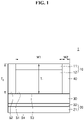
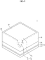
- an all-solid secondary battery 1 may include: a cathode layer 10; an anode layer 20; and a solid electrolyte layer 30 between the cathode layer 10 and the anode layer 20, wherein the cathode layer 10 may include a positive electrode current collector 11 and a positive active material layer 12 on one side or both (e.g., top and bottom) sides of the positive electrode current collector, and the anode layer 20 includes a negative electrode current collector 21 and a first negative active material layer 22 on the negative electrode current collector 21, and a flame retardant inactive member 40 on one side of the cathode layer 10.
- the cathode layer 10 may include a positive electrode current collector 11 and a positive active material layer 12 on one side of the positive electrode current collector.
- a flame retardant inactive member 40 may be on one side of the cathode layer 10.
- the inactive member 40 may be on one side of the positive active material layer 12 and the positive electrode current collector 11.
- the inactive member 40 may be on one side of the positive active material layer 12 and on one side of the positive electrode current collector 11 facing the solid electrolyte layer 30.
- an occurrence of cracks in the solid electrolyte layer 30 during a manufacturing process of the all-solid secondary battery and/or a charge/discharge process of the all-solid secondary battery may be prevented or reduced, and as a result, the cycle characteristics of the all-solid secondary battery may be improved.
- an all-solid secondary battery 1 not including the flame retardant inactive member 40 as uneven pressure is applied on the solid electrolyte layer 30 contacting the cathode layer 10, cracks may occur during the manufacturing process of the all-solid secondary battery 1 and/or a charge/discharge process of the all-solid secondary battery 1, and as a result, the likelihood of a short circuit occurrence may increase.
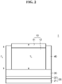
- a thickness (T2) of the flame retardant inactive member 40 may be equal to or less than a thickness (T1) of the cathode layer 10. Because a thickness (T2) of the flame retardant inactive member 40 may be equal to or less than a thickness (T1) of the cathode layer 10, the cathode layer 10 and the solid electrolyte layer 30 may be sufficiently adhered (to one another), and thereby the interfacial resistance between the cathode layer 10 and the solid electrolyte layer 30 may be reduced. In some embodiments, as the solid electrolyte layer 30 may be sufficiently sintered during the manufacturing process of the all-solid secondary battery 1, the internal resistance of the solid electrolyte layer 30 or the all-solid secondary battery 1 including the same may be reduced.
- a thickness (T2) of the flame retardant inactive member 40 may be substantially the same as, for example, a thickness (T1) of the cathode layer 10.
- a thickness (T2) of the flame retardant inactive member 40 may be substantially identical to a thickness (T1) of the cathode layer 10, the uniformity of the pressure applied to the solid electrolyte layer 30 at the time of the manufacture of an all-solid secondary battery 1 and/or a charge/discharge process may be improved. Therefore, cracks of the solid electrolyte layer 30 occurring at the time of a manufacture and/or a charge/discharge process may be suppressed or reduced, and thereby a short circuit occurrence in the all-solid secondary battery may be suppressed or reduced.
- a thickness (T2) of the flame retardant inactive member 40 may be smaller than, for example, a thickness (T1) of the cathode layer 10.
- a thickness (T2) of the flame retardant inactive member 40 may be smaller than, for example, a thickness (T1) of the cathode layer 10, and bigger than a thickness of the positive active material layer 12.
- a thickness (T2) of the flame retardant inactive member 40 may be less than a thickness of, for example, the positive active material layer 12.
- a thickness (T2) of the flame retardant inactive member 40 may be, for example, 50 % to 120 %, 60 % to 120 %, 70 % to 120 %, 80 % to 120 %, 80 % to 110 %, 80 % to 100 %, 90 % to 100 %, or 95 % to 100% of a thickness (T1) of the cathode layer 10.
- a thickness (T2) of the flame retardant inactive member 40 may be, for example, 70 % to 100 %, 80 % to 100 %, 90 % to 100 %, or 95 % to 100 % of a thickness (T1) of the cathode layer 10.
- a thickness (T2) of the flame retardant inactive member 40 is excessively thicker than a thickness (T1) of the cathode layer 10
- a pressure may not be applied properly at the cathode layer 10 during a manufacturing process of an all-solid secondary battery 1, and the solid electrolyte layer 30 in contact with the cathode layer 10 may not be sufficiently pressed. Therefore, the interfacial resistance between the cathode layer 10 and the solid electrolyte layer 30 may be increased, and as a result, the cycle characteristics of the all-solid secondary battery may be deteriorated.
- the solid electrolyte layer 30 in contact with the cathode layer 10 may not be sufficiently pressed.
- a thickness (T2) of the flame retardant inactive member 40 is excessively thinner than a thickness (T1) of the cathode layer 10
- a pressure may not be evenly applied at the solid electrolyte layer 30 in contact with the cathode layer 10 during a manufacturing process of an all-solid secondary battery 1. Therefore, cracks of the solid electrolyte layer 30 occurring during a manufacturing process and/or a charge/discharge process of the all-solid secondary battery 1 may be increased, and thereby a short circuit occurrence of the all-solid secondary battery may be increased or the cycle characteristics are deteriorated.
- a thickness (T2) of the inactive member 40 is excessively thin, the effect of the addition of the inactive member may be minimized or reduced.
- the flame retardant inactive member 40 may be around (e.g., surround) the cathode layer 10 (e.g., view in a thickness direction or in a plan view) and contact (e.g., be directly on) the solid electrolyte layer 30. Because the flame retardant inactive member 40 may surround (e.g., lateral outer side surface) the cathode layer 10 and contact the solid electrolyte layer, the cracks of the solid electrolyte layer 30 that occur in the solid electrolyte layer 30 not contacting the cathode layer 20 during the pressing process by a pressure difference may be effectively suppressed or reduced.
- the flame retardant inactive member 40 may surround of the cathode layer 10 and may be separated from the anode layer 20, or for example, from the first negative active material layer 22.
- the flame retardant inactive member 40 surrounds the cathode layer 10, contacts the solid electrolyte layer 30, and is separated from the anode layer 20. Therefore, the possibility of a short circuit occurrence due to a physical contact of the cathode layer 10 and the first negative active material layer 22 or to an overcharge of lithium may be suppressed or reduced.
- the flame retardant inactive member 40 may extend from a side of the cathode layer 10 to a distal end portion of the solid electrolyte layer 30. As the flame retardant inactive member 40 extends to the distal end portion of the solid electrolyte layer 30, the cracks at the distal end portion of the solid electrolyte layer 30 may be suppressed or reduced.
- the distal end portion of the solid electrolyte layer 30 may be an outermost portion contacting a side surface of the solid electrolyte layer 30.
- the flame retardant inactive member 40 may extend to the outermost portion contacting a side of the solid electrolyte layer 30.
- the flame retardant inactive member 40 may be separated from the anode layer 20, or more for example, from the first negative active material layer 22. Therefore, the flame retardant inactive member 40 may extend to the distal end portion of the solid electrolyte layer 30, but does not contact the anode layer 20. The flame retardant inactive member 40 fills the space extending to the distal end portion of the solid electrolyte layer 30 from, for example, a side of the cathode layer 30.
- a width (W2) of the flame retardant inactive member 40 extending from one side of the cathode layer 10 to the end of the solid electrolyte layer 30 is 1 % to 30 %, 1 % to 25%, 1 % to 20%, 1 % to 15%, 1 % to 10% or 1 % to 5% of a width (W1) of the cathode layer (10).
- the width (W2) of the flame retardant inactive member 40 is excessively wide, an energy density of the all-solid secondary battery 1 may be reduced.
- the width (W2) of the flame retardant inactive member 40 may be excessively narrow, the effect of disposing the flame retardant inactive member may be minimized or reduced.
- An area (S1) of the cathode layer 10 is smaller than an area (S3) of the solid electrolyte layer 30 in contact with the cathode layer 10, and the flame retardant inactive member 40 is arranged to surround a side of the cathode layer 10, and compensates for a difference in area between the cathode layer 10 and the solid electrolyte layer 30.
- an area (S2) of the flame retardant inactive member 40 (S2) compensates for a difference in area between the area (S1) of the cathode layer 10 and the area (S3) of the solid electrolyte layer 30, cracks of the solid electrolyte layer 30 generated by a pressure difference during the pressing process can be effectively suppressed or reduced.
- the area (S1) of the cathode layer 10 may be less than 100 %, 99 % or less, 98 % or less, 97 % or less, 96 % or less, 95 % or less, or 93 % or less of the area (S3) of the solid electrolyte layer 30.
- the area (S1) of the cathode layer 10 may be 50 % to less than 100 %, 50 % to 99 %, 55 % to 98 %, 60 % to 97 %, 70 % to 96 %, 80 % to 95 %, or 85 % to 95 % of the area (S3) of the solid electrolyte layer 30.
- the area (S1) of the cathode layer 10 When the area (S1) of the cathode layer 10 is equal to or bigger than the area (S3) of the solid electrolyte layer 30, a short circuit may occur because the cathode layer 10 may physically contact the first negative active material layer 22 or the possibility of a short circuit may increase due to an overcharge of lithium and/or the like.
- the area (S1) of the cathode layer 10 may be equal to, for example, the area of positive active material layer 12.
- the area (S1) of the cathode layer 10 may be equal to, for example, the area of the positive electrode current collector 11.
- the area (S2) of the flame retardant inactive member 40 may be 50 % or less, 40 % or less, 30 % or less, 20 % or less or 10% or less of the area (S1) of the cathode layer 10.
- the area (S2) of the flame retardant inactive member 40 may be 1 % to50 %, 5 % to 40 %, 5 % to 30 %, 5 % to 20 % or 5% to 15% of the area (S1) of the cathode layer 10.
- the area (S1) of the cathode layer 10 may be smaller than an area (S4) of the negative electrode current collector 21.
- the area (S1) of the cathode layer 10 may be less than 100 %, 99 % or less, 98 % or less, 97 % or less, 96 % or less, 95 % or less, or 93 % or less of the area (S4) of the negative electrode current collector 21.
- the area (S1) of the cathode layer 10 may be 50 % to less than 100 %, 50 % to 99 %, 55 % to 98 %, 60 % to 97 %, 70 % to 96 %, 80 % to 95 %, or 85 % to 95 % of the area (S4) of the negative electrode current collector 21.
- the area (S4) of the negative electrode current collector 21 may be, for example, the same with the area of the anode layer 20.
- the area (S4) of the negative electrode current collector 21 may be, for example, the same with the area of the first negative active material 22.
- the same area, length, width, thickness and/or form include all cases having “substantially the same” area, length, width, thickness and/or form except for cases wherein the area, length, width, thickness and/or form are intentionally different.
- the same area, length, width, and/or thickness include the embodiments wherein the unintentional difference of the area, length, width, and/or thickness of the subjects of comparison are, for example, less than 1 %, less than 0.5 %, or less than 0.1 %.
- the flame retardant inactive member 40 may be, for example, a gasket.
- the gasket is utilized as the inactive member 40, the cracks of the solid electrolyte layer 30 generated by a pressure difference during the pressing process may be effectively suppressed or reduced.
- the flame retardant inactive member 40 may have, for example, a single layer structure. In some embodiments, the flame retardant inactive member 40 may have a multilayer structure. Each layer of the flame retardant inactive member 40 having a multi-layer structure may have a different composition. The flame retardant inactive member having a multi-layer structure may have, for example, a bi-layer structure, a tri-layer structure, a quadra-layer structure or a penta-layer structure. The flame retardant inactive member 40 having a multi-layer structure may include, for example, one or more adhesive layers and one or more support layers.
- An adhesive layer may effectively prevent (or reduce) the separation between the cathode layer 10 and the solid electrolyte layer 30 due, for example, to a volume change of the cathode layer 10 generated during a charge/discharge process of the all-solid secondary battery 1, and may improve the strength of the inactive member 40 film by providing a binding strength between a support layer and another layer.
- a support layer may provide a supporting strength to the flame retardant inactive member 40 and may prevent (or reduce) the solid electrolyte layer 30 from being unevenly pressurized in the pressurization or a charge/discharge process, and may prevent (or reduce) deformation of the all-solid secondary battery 1.
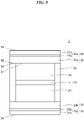
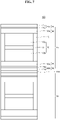
- the all-solid secondary battery 1 may include: a cathode layer 10; and anode layer 20; and a solid electrolyte layer 30 between the cathode layer 10 and the anode layer 20, wherein the cathode layer 10 includes a positive electrode current collector 11 and a first positive active material layer 12a and a second positive active material layer 12b respectively on both (e.g., top and bottom) sides of the positive electrode current collector 11, the solid electrolyte layer 30 may include a first solid electrolyte layer 30a in contact with the first positive active material layer 12a and a second solid electrolyte layer 30b in contact with the second positive active material layer 12b, the anode layer 20 may include a first anode layer 20a (includes 21a and 22a) in contact with the first solid electrolyte layer 30a and a second anode layer 20b (includes 21b and 22b) in contact with the second solid electrolyte layer 30b, and the flame retardant inactive member
- the all-solid secondary battery 1 may have a bi-cell structure.
- the solid electrolyte layer 30 and the anode layer 20 may be arranged facing each other substantially symmetrically, and the deformation of the all-solid secondary battery 1 due to a pressure applied at the time of a manufacture may be effectively suppressed or reduced. Therefore, cracks of the solid electrolyte layer 30 occurring at the time of a manufacture and/or a charge/discharge process may be suppressed or reduced, and thereby a short circuit occurrence of the all-solid secondary battery may be prevented or reduced and the cycle characteristics of the all-solid secondary battery may be further improved. Further, because only one positive electrode current collector 11 may be utilized for the plurality of positive active material layers 12a and 12b, the energy density of the all-solid secondary battery 1 may be increased.
- the flame retardant inactive member 40 may include a matrix and a filler.
- the matrix may include, for example, a substrate and a reinforcing agent.
- the matrix may include, for example, a substantially fibrous substrate and a substantially fibrous reinforcing agent.
- the matrix may include a substrate, the matrix may have elasticity.
- the matrix may effectively supplement for the volume change during a charge/discharge process of the all-solid secondary battery 1 and may be at one or more suitable locations.
- the substrate included in the matrix may include, for example, a first fibrous material.
- the substrate may include a first fibrous material, it may effectively supplement for the volume change of the cathode layer 30 generated during a charge/discharge process of the all-solid secondary battery 1, and the deformation of the flame retardant inactive member 40 due to a volume change of the cathode layer 30 may be effectively suppressed or reduced.
- the first fibrous material may have, for example, an aspect ratio of 5 or more, 20 or more, or 50 or more.
- the first fibrous material may have, for example, an aspect ratio of 5 to 1000, 20 to 1000, or 50 to 1000.
- the first fibrous material may be, for example, an insulating material.
- the first fibrous material may be an insulating material, it may effectively prevent or reduce a short circuit between the cathode layer 30 and the anode layer 20 due to a lithium dendrite which forms during a charge/discharge process of the all-solid secondary battery 1.
- the first fibrous material may include, for example, at least one material/substance selected from pulp fibers, insulating polymer fibers, and/or ion-conductive polymer fibers.
- Pulp fibers are fibers obtained from plant materials. Pulp fibers may include, for example, cellulose fibers. The cellulose fibers may be a cellulose microfiber or a cellulose nanofiber.
- Insulating polymer fibers may be, for example, polyimide fibers, polyaramid fibers, polyethylene fibers, polyphenylene sulfide fibers, and/or the like.
- Ion-conductive polymer fibers may be, for example, polystyrenesulfonate (PSS) fibers, polyvinylidene fluoride-hexafluoropropylene (PVDF-HFP) copolymer fibers, polyvinyl fluoride (PVF) fibers, and/or polyvinylidene fluoride (PVDF) fibers.
- PSS polystyrenesulfonate
- PVDF-HFP polyvinylidene fluoride-hexafluoropropylene
- PVDF polyvinyl fluoride
- PVDF polyvinylidene fluoride
- the strength of the matrix may be improved as the matrix includes a reinforcing agent. Therefore, the matrix may prevent or reduce an excessive volume change at a charge/discharge process of the all-solid secondary battery 1 and prevent or reduce deformation of the all-solid secondary battery 1.
- the reinforcing agent included in the matrix may include, for example, a second fibrous material.
- the strength of the matrix may be more evenly increased.
- the second fibrous material may have, for example, an aspect ratio of 3 or more, 5 or more, or 10 or more.
- the second fibrous material may have, for example, an aspect ratio of 3 to 100, 5 to 100, or 10 to 100.
- the second fibrous material may be, for example, a flame retardant material.
- the second fibrous material may be a flame retardant material, the ignition due to a thermal runaway generated by a charge/discharge process of the all-solid secondary battery 1 or an external impact, may be effectively suppressed or reduced.
- the second fibrous material may be, for example, glass fibers, metal oxide fibers, ceramic fibers, and/or the like.
- a glass fiber may be determined by the composition of the metal oxide constituting the glass.
- Glass fibers may be, for example, silicate glass fibers.
- Metal oxide fibers are, for example, silica (SiO 2 ) fibers, alumina (Al 2 O 3 ) fibers, bohemite fibers, and/or the like.
- Ceramic fibers may be, for example, silicon carbide fibers.
- the content (e.g., amount) of the substrate included in the flame retardant inactive member 40 may be, for example, 5 parts by weight to 80 parts by weight, 5 parts by weight to 70 parts by weight, 5 parts by weight to 60 parts by weight, 5 parts by weight to 50 parts by weight, 5 parts by weight to 40 parts by weight, or 5 parts by weight to 30 parts by weight, with respect to 100 parts by weight of the flame retardant inactive member 40.
- the content (e.g., amount) of the reinforcing agent included in the flame retardant inactive member 40 may be, for example, 4 parts by weight to 40 parts by weight, 4 parts by weight to 30 parts by weight, 4 parts by weight to 25 parts by weight, 4 parts by weight to 20 parts by weight, or 4 parts by weight to 15 parts by weight, with respect to 100 parts by weight of the flame retardant inactive member 40.
- the flame retardant inactive member 40 may include a filler in addition to the matrix.
- the filler may be inside the matrix, or on the surface of the matrix, or both (e.g., simultaneously) inside and on the surface.
- the filler may be, for example, an inorganic material.
- the filler included in the flame retardant inactive member 40 may be, for example, a moisture getter (adsorbs moisture).
- the filler for example, by adsorbing moisture at a temperature of less than 100 °C may remove or decrease the remaining moisture in the all-solid secondary battery 1 and may prevent or reduce deterioration of the all-solid secondary battery 1. Further, when the temperature of the all-solid secondary battery 1 is increased to 150 °C or more due to a thermal runaway generated by a charge/discharge process or an external impact, the filler may release the adsorbed moisture, and the ignition of the all-solid secondary battery 1 may be effectively suppressed or reduced.
- the filler is, for example, a flame retardant.
- the filler may be, for example, a moisture adsorbent metal hydroxide.
- a metal hydroxide included in the filler may be, for example, Mg(OH) 2 , Fe(OH) 3 , Sb(OH) 3 , Sn(OH) 4 , TI(OH) 3 , Zr(OH) 4 , Al(OH) 3 or one or more combinations thereof.
- the content (e.g., amount) of the filler included in the flame retardant inactive member 40 may be, for example, 10 parts by weight to 80 parts by weight, 20 parts by weight to 80 parts by weight, 30 parts by weight to 80 parts by weight, 40 parts by weight to 80 parts by weight, 50 parts by weight to 80 parts by weight, or 60 parts by weight to 80 parts by weight, or 65 parts by weight to 80 parts by weight, with respect to 100 parts by weight of the flame retardant inactive member 40.
- the flame retardant inactive member 40 may include, for example, a binder.
- the binder may include, for example, a thermosetting polymer.
- a thermosetting polymer may be a polymer that is cured by heat and/or pressure.
- the thermosetting polymer may be, for example, a solid at room temperature.
- the flame retardant inactive member 40 may include, for example, a thermosetting film and/or a cured product thereof.
- a thermosetting polymer may be, for example, Toray's TSA-66.
- the binder may include a general binder utilized in the art.
- the binder may be, for example, a fluorine-based binder such as polyvinylidene fluoride, or an acrylic binder such as polyacrylate.
- the content (e.g., amount) of the binder included in the flame retardant inactive member 40 may be, for example, 1 part by weight to 10 parts by weight, 1 part by weight to 5 parts by weight, or 1 part by weight to 3 parts by weight, with respect to 100 parts by weight of the flame retardant inactive member 40.
- the flame retardant inactive member 40 may further include other suitable materials in addition to the above-described substrate, reinforcing agent, filler and binder.
- the flame retardant inactive member 40 may further include one or more materials/substances selected from, for example, a paper, an insulating polymer, an ion-conductive polymer, an insulating inorganic material, an oxide-based solid electrolyte, and a sulfide-based solid electrolyte.
- the insulating polymer may be, for example, an olefin-based polymer such as polypropylene (PP) and/or polyethylene (PE).
- the content (e.g., amount) of the other suitable materials further included in the flame retardant inactive member 40 may be, for example, 1 part by weight to 30 parts by weight, 1 part by weight to 20 parts by weight, 1 part by weight to 10 parts by weight, 1 part by weight to 5 parts by weight, or 1 part by weight to 3 parts by weight, with respect to 100 parts by weight of the flame retardant inactive member 40.
- a density of the substrate or the reinforcing agent included in the flame retardant inactive member 40 may be, for example, 10 % to 300 %, 10 % to 150 %, and 10 % to 140 %, 10 % to 130 %, or 10 % to 120 % of a density of the positive active material included in the positive active material layer 12.
- a density of the substrate may be, for example, 10 % to 300 %, 10 % to 150 %, 10 % to 140 %, 10 % to 130 %, or 10 % to 120 % of a density of the positive active material included in the positive active material layer 12.
- a density of the substrate may be, for example, 50 % to 200 % of a density of the positive active material included in the positive active material layer 12.
- a density of the reinforcing agent may be, for example, 50 % to 300 %, 50 % to 150 %, 50 % to 140 %, 50 % to 130 %, or 50 % to 120 % of a density of the solid electrolyte included in the solid electrolyte layer 30.
- a density of the reinforcing agent may be, for example, 50 % to 200 % of a density of the solid electrolyte included in the solid electrolyte layer 30.
- the flame retardant inactive member 40 may be a member that does not include (e.g., may exclude) a material with a electrochemical activity, such as an electrode active material.
- An electrode active material may be a material that occludes/releases lithium.
- the flame retardant inactive member 40 may be a member composed of a material utilized in the art other than an electrode active material.
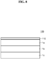
- a conductive flame retardant inactive member 110 may be on one side of the cathode layer 10.
- the conductive flame retardant inactive member 110 may be differentiated from a flame retardant inactive member 40 in that it additionally may include a conductive material and has a conductivity.
- the conductive material may be, for example, graphite, carbon black, acetylene black, ketjen black, denka black, carbon fiber, carbon nanotubes (CNT), graphene, metal fibers, and/or metal powder.
- the conductivity of the conductive flame retardant inactive member 110 at 25 °C may be, for example, more than 1,000 times more or more than 10,000 times more the conductivity of a flame retardant inactive member 40 at 25 °C.
- the content (e.g., amount) of the substrate included in the conductive flame retardant inactive member 110 may be, for example, 5 parts by weight to 80 parts by weight, 5 parts by weight to 70 parts by weight, 5 parts by weight to 60 parts by weight, 5 parts by weight to 50 parts by weight, 5 parts by weight to 40 parts by weight, 5 parts by weight to 30 parts by weight, or 5 parts by weight to 35 parts by weight, with respect to 100 parts by weight of the flame retardant inactive member 110.
- the content (e.g., amount) of the reinforcing agent included in the conductive flame retardant inactive member 110 may be, for example, 4 parts by weight to 40 parts by weight, 4 parts by weight to 30 parts by weight, 4 parts by weight to 25 parts by weight, 4 parts by weight to 20 parts by weight, 4 parts by weight to 15 parts by weight, 4 parts by weight to 10 parts by weight, or 6 parts by weight to 8 parts by weight, with respect to 100 parts by weight of the conductive flame retardant inactive member 110.
- the content (e.g., amount) of the filler included in the conductive flame retardant inactive member 110 may be, for example, 10 parts by weight to 80 parts by weight, 20 parts by weight to 80 parts by weight, 30 parts by weight to 80 parts by weight, 40 parts by weight to 80 parts by weight, 50 parts by weight to 80 parts by weight, or 50 parts by weight to 70 parts by weight, or 50 parts by weight to 60 parts by weight, with respect to 100 parts by weight of the conductive flame retardant inactive member 110.
- the content (e.g., amount) of the binder included in the conductive flame retardant inactive member 110 may be, for example, 1 part by weight to 10 parts by weight, 1 part by weight to 5 parts by weight, or 1 part by weight to 3 parts by weight, with respect to 100 parts by weight of the conductive flame retardant inactive member 110.
- the content (e.g., amount) of the conductive material included in the conductive flame retardant inactive member 110 may be, for example, 1 part by weight to 30 parts by weight, 5 parts by weight to 30 parts by weight, 10 parts by weight to 30 parts by weight, or 15 parts by weight to 30 parts by weight, with respect to 100 parts by weight of the conductive flame retardant inactive member 110.
- a substrate a reinforcing agent, a filler, a binder, and other additional materials included in the conductive flame retardant inactive member 110 may be found, for example, in the section (in the present disclosure) for a flame retardant inactive member 40.
- Positive active material layer 12 may include, for example, a positive active material and a solid electrolyte.
- the solid electrolyte included in the cathode layer 10 may be substantially similar to or different from the solid electrolyte included in the solid electrolyte layer 30. Additional description of the solid electrolyte may be found in the section (in the present disclosure) for a solid electrolyte layer 30.
- Positive active material may be a positive active material that may reversibly absorb or desorb lithium-ions.
- the positive active material may be for example, a lithium transition metal oxide, such as lithium cobalt oxide (LCO), lithium nickel oxide, lithium nickel cobalt oxide, lithium nickel cobalt aluminum hydroxide (NCA), lithium nickel cobalt manganate (NCM), lithium manganate, or lithium iron phosphate, nickel sulfide, copper sulfide, lithium sulfide, iron oxide, vanadium oxide, and/or the like, but is not limited thereto, and any suitable positive active material may be utilized. These materials should be apparent to one of ordinary skill in the art upon reviewing the present disclosure.
- the positive active material may be composed of one positive active material or a mixture (or mixtures) of two or more positive active materials.
- the lithium transition metal oxide may be for example, a compound represented by any one of the formulas Li a A 1-b B b D 2 (where 0.90 ⁇ a ⁇ 1, and 0 ⁇ b ⁇ 0.5); Li a E 1-b B b O 2-c D c (where 0.90 ⁇ a ⁇ 1, 0 ⁇ b ⁇ 0.5, and 0 ⁇ c ⁇ 0.05); LiE 2-b B b O 4-c D c (where 0 ⁇ b ⁇ 0.5, and 0 ⁇ c ⁇ 0.05); Li a Ni 1-b-c Co b B c D ⁇ (where 0.90 ⁇ a ⁇ 1, 0 ⁇ b ⁇ 0.5, 0 ⁇ c ⁇ 0.05, and 0 ⁇ ⁇ ⁇ 2); LiaNi 1-b-c Co b B c O 2- ⁇ F ⁇ (where 0.90 ⁇ a ⁇ 1, 0 ⁇ b ⁇ 0.5, 0 ⁇ c ⁇
- A is Ni, Co, Mn, or one or more combinations thereof;
- B is Al, Ni, Co, Mn, Cr, Fe, Mg, Sr, V, a rare earth element or one or more combinations thereof;
- D is O, F, S, P, or one or more combinations thereof;
- E is Co, Mn, or one or more combinations thereof;
- F is F, S, P, or one or more combinations thereof;
- G is Al, Cr, Mn, Fe, Mg, La, Ce, Sr, V, or one or more combinations thereof;
- Q is Ti, Mo, Mn, or one or more combinations thereof;
- I is Cr, V, Fe, Sc, Y, or one or more combinations;
- J is V, Cr, Mn, Co, Ni, Cu, or one or more combinations thereof.
- the coating layer added to the surface of such a compound includes compounds of a coating element, for example, oxides of a coating element, hydroxides of a coating element, oxyhydroxides of a coating element, oxycarbonate of a coating element, or hydroxycarbonates of a coating element.
- the compound that forms such a coating layer may be amorphous or crystalline.
- a coating element included in the coating layer is Mg, Al, Co, K, Na, Ca, Si, Ti, V, Sn, Ge, Ga, B, As, Zr, or a mixture (or one or more mixtures) thereof.
- a coating layer formation method may be selected within a range that does not adversely affect the physical properties of the positive active material.
- a coating method is, for example, a spray coating, an immersion method, and/or the like. Specific coating methods should be apparent to one of ordinary skill in the art upon reviewing the present disclosure, and a detailed description thereof will not be provided.
- the positive active material may include, for example, a lithium salt of a transition metal oxide which has a layered rock salt type or kind structure among the above-described lithium transition metal oxides.
- "Layered rock salt type or kind structure” may be for example, a structure in which oxygen atom layers and metal atom layers are alternately arranged in the direction of ⁇ 111 > of a cubic rock salt type or kind structure, and thereby, each atom layer forms a two-dimensional plane.
- Cubic rock salt type or kind structure may be a structure of sodium chloride (NaCI) type or kind which is a kind of a crystal structure, and for example, face centered cubic (fcc) lattices each formed by cations and anions are displaced from each other by 1/2 of the ridge of the unit lattice.
- NaCI sodium chloride
- fcc face centered cubic
- a positive active material includes a three-element lithium transition metal oxide having a layered rock type or kind structure, the energy density and thermal stability of the all-solid secondary battery 1 may be further improved.
- the positive active material may be covered by a coating layer as described above.
- the coating layer may be any material that is suitable as a coating layer for a positive active material of an all-solid secondary battery. These materials should be apparent to one of ordinary skill in the art upon reviewing the present disclosure.
- the coating layer may be, for example, Li 2 O-ZrO 2 (LZO).
- the positive active material is, for example, a three-element lithium transition metal oxide such as NCA or NCM and contain nickel (Ni), by increasing the capacity density of the all-solid secondary battery, it may be possible to decrease the metal elution of the positive active material in a charging state. As a result, the cycle properties of an all-solid secondary battery 1 in a charging state may be improved.
- the shape of the positive active material may be, for example, a particle shape such as a substantially true sphere, an elliptical sphere, and/or the like.
- the particle diameter of the positive active material is not limited and may be in a range applicable to a positive active material of the all-solid secondary battery.
- An amount of the positive active material of the cathode layer 10 is not limited either, and it may be in a range applicable to a cathode layer of the all-solid secondary battery.
- the positive active material layer 12 may include, for example, a solid electrolyte.
- a solid electrolyte included in a cathode layer 10 may be substantially the same as or different from a solid electrolyte included in a solid electrolyte layer 30. Additional description of the solid electrolyte may be found, for example, in the section (in the present disclosure) for a solid electrolyte layer 30.
- the solid electrolyte included in the positive active material layer 12 may have a smaller Dso average particle diameter compared to the solid electrolyte included in the solid electrolyte layer 30.
- Dso average particle diameter of the solid electrolyte included in the positive active material layer 12 may be, compared to the average particle diameter of the solid electrolyte included in the solid electrolyte layer 30, 90% or less, 80% or less, 70% or less, 60% or less, 50% or less, 40% or less, 30% or less, or 20% or less.
- Dso average particle diameter may be, for example, a median particle diameter.
- the median particle diameter (D 50 ) is the size of the particle corresponding to a 50% cumulative volume when the volume is calculated from a side of the smallest particles in the particle size distribution measured by, for example, a laser diffraction method.
- the positive active material layer 12 may include a binder.
- the binder may be, for example, styrene butadiene rubber (SBR), polytetrafluoroethylene, polyvinylidene fluoride, polyethylene, and/or the like but is not limited thereto, and any suitable binder may be utilized.
- SBR styrene butadiene rubber
- polytetrafluoroethylene polytetrafluoroethylene
- polyvinylidene fluoride polyethylene
- polyethylene and/or the like but is not limited thereto, and any suitable binder may be utilized.
- the positive active material layer 12 may include a conductive material.
- the conductive material may be, for example, graphite, carbon black, acetylene black, ketjen black, carbon fiber, metal powder, and/or the like but is not limited thereto, and any suitable conductive material may be utilized. These materials should be apparent to one of ordinary skill in the art upon reviewing the present disclosure.
- the positive active material layer 12 may further include an additive such as a filler, a coating material, a dispersant, an ion conductivity supplement, and/or the like, in addition to the above-described positive active material, the solid electrolyte, the binder, and/or the conductive material.
- an additive such as a filler, a coating material, a dispersant, an ion conductivity supplement, and/or the like, in addition to the above-described positive active material, the solid electrolyte, the binder, and/or the conductive material.
- any suitable material utilized in an electrode of an all-solid secondary battery may be utilized. These materials should be apparent to one of ordinary skill in the art upon reviewing the present disclosure.
- a plate or foil made of indium (In), copper (Cu), magnesium (Mg), stainless steel, titanium (Ti), iron (Fe), cobalt (Co), nickel (Ni), zinc (Zn), aluminum (Al), germanium (Ge), lithium (Li), or an alloy (or one or more alloys) thereof, may be utilized.
- the positive electrode collector 11 may not be provided.
- a thickness of the positive electrode current collector 11 may be, for example, 1 ⁇ m to 100 ⁇ m, 1 ⁇ m to 50 ⁇ m, 5 ⁇ m to 25 ⁇ m, or 10 ⁇ m to 20 ⁇ m.
- Solid Electrolyte Layer Solid Electrolyte
- the solid electrolyte layer 30 may include a solid electrolyte between the cathode layer 10 and the anode layer 20.
- the solid electrolyte may be, for example, a sulfide-based solid electrolyte.
- the sulfide-based solid electrolyte may be, for example, one or more compounds/substances selected from, Li 2 S-P 2 S 5 , Li 2 S-P 2 S 5 -LiX (where X is a halogen), Li 2 S-P 2 S 5 -Li 2 O, Li 2 S-P 2 S 5 -Li 2 O-LiI, Li 2 S-SiS 2 , Li 2 S-SiS 2 -LiI, Li 2 S-SiS 2 -LiBr, Li 2 S-SiS 2 -LiCl, Li 2 S-SiS 2 -B 2 S 3 -LiI, Li 2 S-SiS 2 -P 2 S 5 -LiI, Li2S-B2S3, Li2S-P2S5-ZmSn, (where m and n are positive numbers,
- a sulfide-based solid electrolyte may be prepared by, for example, treating the raw material such as Li 2 S or P 2 S 5 by melt quenching or a mechanical milling method. In some embodiments, after this treatment, a heat treatment may be performed.
- the solid electrolyte may be in an amorphous state, a crystalline state or, in a mixed state of these.
- the solid electrolyte for example, may include at least as constituent elements, sulfur (S), phosphorus (P) and/or lithium (Li) among the above-described sulfide solid electrolyte materials.
- the solid electrolyte may be a material including Li 2 S-P 2 S 5 .
- the sulfide solid electrolyte may include, for example, an argyrodite type or kind solid electrolyte represented by Formula 1.
- Formula 1 Li + 12-n-x A n+ X 2- 6-x Y - x , wherein A is P, As, Ge, Ga, Sb, Si, Sn, Al, In, Ti, V, Nb or Ta, X is S, Se or Te, Y is CI, Br, I, F, CN, OCN, SCN, or N 3 , 1 ⁇ n ⁇ 5, and 0 ⁇ x ⁇ 2.
- the sulfide solid electrolyte may be, for example, an argyrodite-type or kind compound including at least one compound/substance selected from Li 7-x PS 6-x Cl x , (0 ⁇ x ⁇ 2), Li 7-x PS 6-x Br x , (0 ⁇ x ⁇ 2), and/or Li 7-x PS 6-x I x , (0 ⁇ x ⁇ 2).
- the sulfide solid electrolyte may be an argyrodite-type or kind compound including at least one compound/substance selected from Li 6 PS 5 Cl, Li 6 PS 5 Br and Li 6 PS S I.
- the density of the argyrodite-type or kind solid electrolyte may be 1.5 g/cc to 2.0 g/cc.
- the argyrodite-type or kind solid electrolyte may have a density of 1.5 g/cc or more, the internal resistance of the all-solid secondary battery may be decreased, and the penetration of a solid electrolyte layer by lithium (Li) may be effectively suppressed or reduced.
- a solid electrolyte layer 30 may include, for example, a binder.
- a binder included in the solid electrolyte layer 30 may be, for example, styrene butadiene rubber (SBR), polytetrafluoroethylene, polyvinylidene fluoride, polyethylene, and/or the like, but is not limited thereto, and any suitable binder may be utilized. These binders should be apparent to one of ordinary skill in the art upon reviewing the present disclosure.
- the binder in the solid electrolyte layer 30 may be substantially the same as or different from the binder included in the positive active material layer 12 and/or the negative active material layer 22. A binder may not be provided.
- the content (e.g., amount) of the binder included in the solid electrolyte layer 30 may be 0 to 10 wt%, 0 to 5 wt%, 0 to 3 wt%, 0 to 1 wt%, 0 to 0.5 wt%, or 0 to 0.1 wt%, with respect to the total weight of the solid electrolyte layer 30.
- a first negative active material layer 22 may include for example, a negative active material and a binder.
- the negative active material included in the first negative active material layer 22 may have, for example, a particle form.
- the average particle diameter of the negative active material having a particle form is, for example, 4 ⁇ m or less, 3 ⁇ m or less, 2 ⁇ m or less, 1 ⁇ m or less, or 900 nm or less.
- the average particle diameter of the negative active material having a particle form is, for example, 10 nm to 4 ⁇ m, 10 nm to 3 ⁇ m, 10 nm to 2 ⁇ m or less, 10 nm to 1 ⁇ m, or 10 nm to 900 nm.
- the reversible absorption and/or desorption of lithium during a charge/discharge process may be easier, when the negative active material has the average particle diameter in the foregoing ranges.
- the average particle diameter of the negative active material may be, for example, a median diameter (Dso) measured utilizing a laser particle size distribution device.
- the negative active material included in the first negative active material layer 22 may include at least one material/substance/compound selected from a carbon-based negative active material, metal negative active material and metalloid negative active material.
- a carbon-based negative active material may be for example amorphous carbon.
- Amorphous carbon may be, for example, carbon black (CB), acetylene black (AB), furnace black (FB), ketjen black (KB), graphene, and/or the like, but is not limited thereto, and all material classified as an amorphous carbon in the art may be utilized. These materials should be apparent to one of ordinary skill in the art upon reviewing the present disclosure.
- Amorphous carbon has a very low or no crystallinity and is distinguished from crystalline carbon or graphite carbon.
- a metal or metalloid negative active material may include at least one element selected from the group including (e.g., consisting of) gold (Au), platinum (Pt), palladium (Pd), silicon (Si), silver (Ag), aluminum (Al), bismuth (Bi), tin (Sn) and zinc (Zn), but is not limited thereto, and all materials/elements/alloys utilized as a metal negative active material or metalloid negative active material forming alloys or compounds with lithium in the art may be utilized. These materials/elements/alloys should be apparent to one of ordinary skill in the art upon reviewing the present disclosure. For example, nickel (Ni) may not be a negative active material because it does not form alloys with lithium.
- the first negative active material layer 22 may include a kind of a negative active material, or a mixture (or mixtures) of multiple different negative active materials.
- the first negative active material layer 22 may include amorphous carbon only and/or, one or more elements selected from the group including (e.g., consisting of) gold (Au), platinum (Pt), palladium (Pd), silicon (Si), silver (Ag), aluminum (Al), bismuth (Bi), tin (Sn), and zinc (Zn).
- the first negative active material layer 22 includes a mixture of amorphous carbon and one or more elements selected from the group including (e.g., consisting of) gold (Au), platinum (Pt), palladium (Pd), silicon (Si), silver (Ag), aluminum (Al), bismuth (Bi), tin (Sn), and zinc (Zn).
- the mixing ratio of the mixture of amorphous carbon and gold and/or the like may be, for example, 10:1 to 1:2, 5:1 to 1:1, or 4:1 to 2:1, but is not limited thereto, and ratio is selected according to the properties of the all-solid secondary battery 1 that are desired. As the negative active material has such a composition, the cycle properties of the all-solid secondary battery 1 may be further improved.
- the negative active material included in the first negative active material layer 22 may include, for example, a mixture of first particles made of amorphous carbon and second particles made of a metal or a metalloid.
- the metal or metalloid may include gold (Au), platinum (Pt), palladium (Pd), silicon (Si), silver (Ag), aluminum (Al), bismuth (Bi), tin (Sn), and/or zinc (Zn).
- a metalloid may be, alternatively, a semiconductor.
- An amount of the second particle may be, with respect to the total weight of the mixture, 8 wt% to 60 wt%, 10 wt% to 50 wt%, 15 wt% to 40 wt%, or 20 wt% to 30 wt%. As the amount of the second particle is in the foregoing ranges, for example, the cycle properties of the all-solid secondary battery 1 may be further improved.
- the binder included in the first negative active material layer 22 may be, for example, styrene-butadiene rubber (SBR), polytetrafluoroethylene, polyvinylhylidene fluoride, polyethylene, vinylidene fluoride/hexafluoropropylene copolymers, polyacrylonitrile, polymethyl methacrylate, and/or the like, but is not limited thereto, and any suitable binder in the art may be utilized.
- SBR styrene-butadiene rubber
- polytetrafluoroethylene polyvinylhylidene fluoride
- polyethylene vinylidene fluoride/hexafluoropropylene copolymers
- polyacrylonitrile polymethyl methacrylate
- the binder may be composed of one binder or multiple different binders.
- the first negative active material layer 22 may be stabilized on the negative electrode current collector 21. Further, in a charge/discharge process, despite the volume change and/or relative position change of the first negative active material layer 22, the cracking of the first negative active material layer 22 may be suppressed or reduced. For example, when the first negative active material layer 22 does not include a binder, it may be possible to easily separate the first negative active material layer 22 from the negative electrode current collector 21. In the portion of the first negative active material layer 22 disengaged from the negative electrode current collector 21, the negative electrode current collector 21 may be exposed and contacts the solid electrolyte layer 30, and a short circuit may be more likely to occur.
- the first negative active material layer 22 may be prepared by, for example, applying the slurry where materials that make up the first negative active material layer 22 are dispersed, on the negative electrode current collector 21, and by drying it.
- the negative active material in the slurry may be dispersed stably.
- the slurry when the slurry is applied on the negative electrode current collector 21 by a screen printing method, it may be possible to suppress or reduce the clogging of the screen (for example, clogging by agglomerates of the negative active material).
- the first negative active material layer 22 may further include an additive utilized for an all-solid secondary battery, such as a filler, a coating material, a dispersant, an ion conductivity supplement, and/or the like.
- an additive utilized for an all-solid secondary battery such as a filler, a coating material, a dispersant, an ion conductivity supplement, and/or the like.
- Anode Layer first negative Active Material Layer
- a thickness of the first negative active material layer 22 may be, for example, 50% or less, 40% or less, 30% or less, 20% or less, 10% or less, or 5% or less of a thickness of the positive active material layer 12.
- a thickness of the first negative active material layer 22 may be, for example, 1 ⁇ m to 20 ⁇ m, 2 ⁇ m to 10 ⁇ m, or 3 ⁇ m to 7 ⁇ m.
- the energy density of the all-solid secondary battery 1 may be lowered, and the internal resistance of the all-solid secondary battery 1 may be increased by the first negative active material layer 22, and the cycle properties of the all-solid secondary battery 1 may be difficult to be improved upon.
- the charge capacity of the first negative active material layer 22 may also be reduced.
- the charge capacity of the first negative active material layer 22 may be, for example, 50% or less, 40% or less, 30% or less, 20% or less, 10% or less, 5% or less, or 2% or less, compared to the charge capacity of the positive active material layer 12.
- the charge capacity of the first negative active material layer 22 may be, for example, 0.1% to 50%, 0.1% to 40%, 0.1% to 30%, 0.1% to 20%, 0.1% to 10%, 0.1% to 5%, or 0.1 % to 2%, of the charge capacity of the positive active material layer 12.
- the charge capacity of the first negative active material layer 22 is excessively small (e.g., outside of the foregoing ranges)
- the first negative active material layer 22 may become very thin, and the lithium dendrite formed between the first negative active material layer 22 and the negative electrode current collector 21 in the repeated charge/discharge processes, collapses the first negative active material layer 22 and the cycle properties of the all-solid secondary battery 1 may be difficult to be improved upon.
- the energy density of the all-solid secondary battery 1 may be lowered, and the internal resistance of the all-solid secondary battery 1 may be increased by the first negative active material layer 22, and the cycle properties of the all-solid secondary battery 1 may be difficult to be improved upon.
- the charge capacity of the positive active material layer 12 may be obtained by multiplying the charge capacity density (mAh/g) of the positive active material by the mass of the positive active material in the positive active material layer 12.
- the value of charge capacity density ⁇ mass may be calculated for each positive active material, and the total sum of all the values is the charge capacity of the positive active material layer 12.
- the charge capacity of the first negative active material layer 22 is calculated in substantially the same way.
- the charge capacity of the first negative active material layer 22 may be obtained by multiplying the charge capacity density (mAh/g) of the negative active material by the mass of the negative active material of the first negative active material layer 22.
- the value of charge capacity density ⁇ mass may be calculated for each negative active material, and the total sum of all the values is the capacity of the first negative active material layer 22.
- the charge capacity density of the positive active material and the negative active material may be estimated by utilizing an all-solid half-cell that uses lithium metal as a relative electrode.
- the charge capacity of the positive active material layer 12 and the first negative active material layer 22 may be directly measured by utilizing the charge capacity measurement utilizing an all-solid half-cell.
- Charge capacity density may be obtained by dividing the measured charge capacity by the mass of each active material.
- the charge capacity of the positive active material layer 12 and the first negative active material layer 22 may be the initial charge capacity measured at the first cycle.
- Anode Layer secondary negative Active Material Layer
- the all-solid secondary battery 1 may further include by charging, for example, the second negative active material layer between the negative electrode current collector 21 and the first negative active material layer 22.
- the second negative active material layer may be a metal layer including lithium or a lithium alloy.
- the metal layer may include lithium or a lithium alloy.
- a lithium alloy for example, may be Li-AI alloy, Li-Sn alloy, Li-In alloy, Li-Ag alloy, Li-Au alloy, Li-Zn alloy, Li-Ge alloy, Li-Si alloy, and/or the like, but is not limited thereto, and any suitable lithium alloy in the art may be utilized.
- the second negative active material layer may be made of one or more of the foregoing alloys or lithium or one or more combinations thereof, or different kinds of alloys.
- the second negative active material layer may be, for example, a plated layer.
- the second negative active material layer may be eluted between the first negative active material layer 22 and the negative electrode current collector 21 during a charging process of the all-solid secondary battery 1.
- a thickness of the second negative active material layer is not limited and the following ranges are merely examples: 1 ⁇ m to 1000 ⁇ m, 1 ⁇ m to 500 ⁇ m, 1 ⁇ m to 200 ⁇ m, 1
- the second negative active material layer is excessively thin (e.g., outside of the foregoing ranges)
- the second negative active material may barely function as a lithium reservoir.
- the second negative active material layer is excessively thick (e.g., outside of the foregoing ranges)
- the mass and volume of the all-solid secondary battery 1 may be increased, and the cycle properties may decline.
- the second negative active material layer may be, for example, a metal foil having a thickness in the foregoing ranges.
- the second negative active material layer may be, for example, arranged between the negative electrode current collector 21 and the first negative active material layer 22 before the assembly of the all-solid secondary battery 1 or, it may be educed (e.g., produced) by charging, between the negative electrode current collector 21 and the first negative active material layer 22 after the assembly of the all-solid secondary battery.
- the second negative active material layer is arranged between the negative electrode current collector 21 and the first negative active material layer 22 before the assembly of the all-solid secondary battery 1
- the second negative active material layer as a metal layer including lithium, may act as a lithium reservoir.
- lithium foil may be disposed between the negative electrode current collector 21 and the first negative active material layer 22 before the assembly of the all-solid secondary battery 1.
- the cycle characteristic of the all-solid secondary battery 1 including the second negative active material layer may be further improved.
- the energy density of the all-solid secondary battery 1 may increase because the second negative active material layer is not included at the time the all-solid secondary battery 1 is assembled.
- the all-solid secondary battery 1 is charged, it is charged beyond the charge capacity of the first negative active material layer 22.
- the first negative active material layer 22 is overcharged. At the beginning of charging, lithium may be occluded in the first negative active material layer 22.
- the negative active material included in the first negative active material layer 22 may form an alloy or a compound with the lithium-ion that came from the cathode layer 10.
- first negative active material layer 22 When the first negative active material layer 22 is charged beyond its capacity, for example, at the back surface of the first negative active material layer 22, for example, between the negative electrode current collector 21 and the first negative active material layer 22, lithium may be educed, and a metal layer corresponding to the second negative active material layer may be formed by the educed lithium.
- the second negative active material layer is a metal layer primarily including (e.g., consisting of) lithium (i.e., metal lithium).
- the first negative active material layer 22 and the second negative active material layer which are metal layers, is ionized and moves in the direction of the cathode layer 10. Therefore, it is possible to utilize lithium as a negative active material in the all-solid secondary battery 1.
- the first negative active material layer 22 may function as a protection layer of the second negative active material layer, i.e., the metal layer, and at substantially the same time, it may suppress the eduction growth of a lithium dendrite. Therefore, a short circuit occurrence and capacity deterioration of the all-solid secondary battery may be suppressed or reduced, and as a result, the cycle characteristics of the all-solid secondary battery may be improved.
- the negative electrode current collector 21, the first negative active material layer 22 and the region between them may be, for example, Li-free areas where lithium (Li) is not included, in the initial state or the state after the discharge.
- the negative electrode current collector 21 may be composed of, for example, a material that does not react with lithium, i.e., that does not form alloys and compounds with lithium.
- the material constituting the negative electrode current collector 21 may be, for example, copper (Cu), stainless steel, titanium (Ti), iron (Fe), cobalt (Co) and nickel (Ni), and/or the like, but is not limited thereto, and any suitable element/material utilized as an electrode current collector in the art may be utilized. These elements/materials should be apparent to one of ordinary skill in the art upon reviewing the present disclosure.
- the negative electrode current collector 21 may include (e.g., consist of) one of the above-described metals, an alloy of two or more metals or a coating material.
- the negative electrode current collector 21 may be, for example, a plate-like or foil form.
- the all-solid secondary battery 1 may further include a thin film including an element capable of forming an alloy with lithium on, for example, the negative electrode current collector 21.
- the thin film may be between the negative electrode current collector 21 and the first negative active material layer 22.
- the thin film may include, for example, an element capable of forming alloys with lithium.
- Elements capable of forming alloys with lithium may be, for example, gold, silver, zinc, tin, indium, silicon, aluminum, bismuth, and/or the like, but are not limited thereto, and all elements that can form an alloy with lithium may be utilized.
- the thin film may be composed of one of these metals, or is composed of an alloy of one or more suitable kinds of metals.
- the eduction shape of the second negative active material layer may be more flattened, wherein the second negative active material layer may be educed between the thin film 24 and the first negative active material layer 22, and the cycle characteristics of the solid secondary battery 1 can be further improved.
- a thickness of the thin film may be, for example, 1 nm to 800 nm, 10 nm to 700 nm, 50 nm to 600 nm, or 100 nm to 500 nm.
- a thickness of the thin film is less than 1 nm, the function of the thin film may be difficult to be exhibited.
- a thickness of the thin film is too increased (e.g., outside of the foregoing ranges), the thin film itself occludes lithium and the amount of the educed lithium at the anode is decreased, thereby reducing the energy density of the all-solid-state battery, and the cycle characteristics of the all-solid secondary battery 1 may decline.
- the thin film may be disposed on the negative electrode current collector 21 by, for example, a vacuum deposition method, a sputtering method, a plating method, and/or the like, but the method is not limited thereto, and all methods utilized to form a thin film in the art may be utilized. These methods should be apparent to one of ordinary skill in the art upon reviewing the present disclosure.
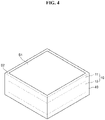
- An all-solid secondary battery structure includes: at least one all-solid secondary battery; and a conductive flame retardant inactive member on one side or both (e.g., top and bottom) sides of the all-solid secondary battery.
- the flame retardant inactive member is disposed on one or both (e.g., top and bottom) sides of the single all-solid secondary battery, or laminated multiple all-solid second batteries, the possibility of a thermal runaway and ignition of the all-solid secondary battery may be reduced, and as a result, safety of the all-solid secondary battery is further improved. Furthermore, as the flame retardant inactive member absorbs the residual moisture inside the all-solid secondary battery, a degradation of the all-solid secondary battery may be prevented or reduced to improve lifespan properties of the all-solid secondary battery.
- the conductive flame retardant inactive member may include, for example, a conductive material.
- the conductive material may be a fibrous conductive material or a particulate conductive material.
- the conductive material may be a carbon-based conductive material, a metal-based conductive material, or a metal-carbon composite conductive material.
- the conductive material may be substantially the same as the conductive material utilized for, for example, the cathode layer.
- the conductive material may be, for example, graphite, carbon black, acetylene black, ketjen black, carbon fiber, and/or metal powder.
- the content (e.g., amount) of the conductive material included in the conductive flame retardant inactive member may be, for example, 1 wt% to 30 wt%, 1 wt% to 20 wt%, 1 wt% to 10 wt%, or 1 wt% to 5 wt%, with respect to the total weight of the conductive flame retardant inactive member.
- the conductive flame retardant inactive member includes a conductive material, the increase of the internal resistance of the all-solid secondary battery structure including a conductive flame retardant inactive member may be suppressed or reduced, and the cycle properties may be improved.
- a thickness of the conductive flame retardant inactive member may be, for example, 1 ⁇ m to 300 ⁇ m, 10 ⁇ m to 300 ⁇ m, 50 ⁇ m to 300 ⁇ m, or 100 ⁇ m to 200 ⁇ m.
- the form of the conductive flame retardant inactive member is not limited, and may be selected according to the form of the all-solid secondary battery included in the all-solid secondary battery structure.
- the conductive flame retardant inactive member may be, for example, in a sheet form, a bar form, or a gasket form.
- the conductive flame retardant inactive member may be disposed, for example, on one side or both (e.g., top and bottom) sides of an all-solid secondary battery.
- the conductive flame retardant inactive member may be disposed, for example, between the laminated plurality of all-solid second batteries.
- the conductive flame retardant inactive member may be disposed, for example, on the uppermost or the lowermost surface of laminated plurality of all-solid second batteries.
- the all-solid secondary battery structure 100 includes an all-solid secondary battery 1; and conductive flame retardant inactive members 110a, 110b disposed on both (e.g., top and bottom) sides of the all-solid secondary battery 1.
- a conductive flame retardant inactive member 110a or 110b may be included on one side of the all-solid secondary battery 1.
- the all-solid secondary battery structure 100 includes a plurality of all-solid second batteries 1a and 1b.
- the conductive flame retardant inactive member 110 is disposed, for example, between the all-solid second batteries 1a and 1b.
- the conductive flame retardant inactive member 110 may be additionally disposed, for example, on the uppermost or the lowermost surface of the stacked all-solid second batteries 1a and 1b.
- the all-solid secondary battery structure 100 includes a plurality of stacked all-solid second batteries 1a, 1b, 1c, and the conductive flame retardant inactive member 110 may be, for example, disposed on the uppermost or the lowermost surface of the stack consisting of a plurality of all-solid second batteries 1a, 1b, and 1c.
- the conductive flame retardant inactive member 110 may be, for example, selectively disposed between at least two of the all-solid second batteries 1a, 1b, and 1c.
- the all-solid secondary battery structure 100 includes a plurality of laminated all-solid second batteries 1a, 1b, 1c, 1d, and 1e
- the conductive flame retardant inactive member 110 is, for example, disposed on the uppermost or the lowermost surface of the stack including (e.g., consisting of) a plurality of all-solid second batteries 1a, 1b, 1c, 1d, and 1e.
- the conductive flame retardant inactive member 110 may be, for example, selectively disposed between at least two of the all-solid second batteries 1a, 1b, 1c, 1d, and 1e.
- Example 1 Flame Retardant Inactive Member (Thickness 120 ⁇ m), Al (OH) 3 , Plate Press.
- Nickel (Ni) foil having a thickness of 10 ⁇ m was prepared as a negative electrode current collector.
- carbon black (CB) having a particle diameter of about 30 nm and silver (Ag) particles having an average particle diameter of about 60 nm were prepared as negative active materials.
- the dried stack was cold-roll pressed with a pressure of 5 ton ⁇ f/cm 2 at a speed of 5 m/sec to flatten the surface of the first negative active material layer of the laminate.
- An anode layer was prepared by the above process.
- a thickness of the first negative active material layer included by the anode layer was about 7 ⁇ m.
- the area of the first negative active material layer and the negative electrode current collector were substantially the same.
- Li 2 O-ZrO 2 (LZO)-coated LiNi 0.8 Co 0.15 Mn 0.05 O 2 (NCM) was prepared as a positive active material.
- the LZO-coated positive active material was prepared according to the method disclosed in Korean Published Patent No. 10-2016-0064942 .
- a binder polytetrafluoroethylene (PTFE) binder (DuPont's Teflon binder) was prepared.
- a conductive material carbon nanofibers (CNF) were prepared.
- the cathode sheet was on one side of the positive electrode current collector composed of carbon-coated aluminum foils, and heated-roll pressed with a pressure of 5 ton ⁇ f/cm 2 at a speed of 5 m/sec at 85 °C.
- a thickness of the cathode layer was about 120 ⁇ m.
- a thickness of the positive active material layer was about 96 ⁇ m, and a thickness of the carbon coated aluminum foil was about 24 ⁇ m.
- the area of the positive active material layer and the positive electrode current collector were substantially the same.
- the prepared mixture was stirred while octyl acetate was being added to prepare slurry.
- the prepared slurry was coated on the 15 ⁇ m thick nonwoven fabric placed on a polyethylene terephthalate (PET) substrate utilizing a bar coater and dried at 80 °C for 10 minutes in the air to obtain a stack.
- the obtained stack was vacuum dried at 80 °C for 2 hours.
- a solid electrolyte layer was prepared by the above process.
- a flame retardant inactive member is prepared by, mixing pulp fibers (cellulose fibers), glass fibers, aluminum hydroxide (Al(OH) 3 ), an acrylic binder and a solvent to make slurry, molding the slurry into a gasket form, and removing the solvent.
- the weight ratio of pulp fiber (cellulose fiber) : glass fiber: aluminum hydroxide (Al(OH) 3 ) : acrylic binder was 20 : 8: 70 :2.
- a thickness of the inactive member was 120 ⁇ m.
- the prepared flame retardant member was left for 1 week at room temperature and then was utilized.
- a solid electrolyte layer was disposed so that the first negative active material layer on the anode layer contacts the solid electrolyte layer, and the cathode layer is disposed on the solid electrolyte layer.
- a laminate was prepared by disposing a gasket that surrounds the cathode layer and contacts the solid electrolyte layer. A thickness of the gasket was about 120 ⁇ m. The flame retardant inactive member was utilized as the gasket. The gasket was arranged to contact a side of the cathode layer and the solid electrolyte layer.
- the cathode layer was arranged at the center of the solid electrolyte layer, and the gasket was arranged to surround the cathode layer and to extend to an end of the solid electrolyte layer.
- the area of the cathode layer was about 90% of the area of the solid electrolyte layer, and on all of the remaining 10% of the area of the solid electrolyte layer on which the cathode layer is not arranged, the gasket was disposed.
- the prepared laminate was plate pressed at 85 °C with a pressure of 500 MPa for 30 minutes.
- the solid electrolyte layer is sintered and the battery characteristics may be improved.
- a thickness of the sintered solid electrolyte layer was about 45 ⁇ m.
- the density of the Li 6 PS 5 Cl solid electrolyte, which is an argyrodite type or kind crystal included in the sintered solid electrolyte layer, was 1.6 g/cc.
- the area of the solid electrolyte layer was substantially the same as the area of the anode layer.
- the pressurized laminate was placed in a pouch and vacuum sealed to prepare an all-solid secondary battery. Parts of the positive electrode current collector and the negative electrode current collector were protruded to the outside of the sealed battery and utilized as a cathode layer terminal and an anode layer terminal.
- Example 2 Flame Retardant Inactive Member (Thickness 120 ⁇ m), Al(OH) 3 , Plate Press.
- An all-solid secondary battery was prepared in substantially the same manner as in Example 1, except that the moisture of the flame retardant inactive member was removed by vacuum heat treating at 80 °C for 5 hours before the flame retardant inactive member was disposed on the solid electrolyte layer.
- Example 3 Flame Retardant Inactive Member (Thickness 140 ⁇ m), Al(OH) 3 , Plate Press.
- An all-solid secondary battery was prepared in substantially the same manner as in Example 1, except that a thickness of the flame retardant inactive member was changed to 140 ⁇ m, and the moisture of the flame retardant inactive member was removed by vacuum heat treating at 80 °C for 5 hours before the flame retardant inactive member was disposed on the solid electrolyte layer.
- Example 4 Flame Retardant Inactive Member (Thickness 110 ⁇ m), Al(OH) 3 , Plate Press.
- An all-solid secondary battery was prepared in substantially the same manner as in Example 1, except that a thickness of the flame retardant inactive member was changed to 110 ⁇ m, and the moisture of the flame retardant inactive member was removed by vacuum heat treating at 80 °C for 5 hours before the flame retardant inactive member was disposed on the solid electrolyte layer.
- Example 5 Flame Retardant Inactive Member (Thickness 70 ⁇ m), Al(OH) 3 , Plate Press.
- An all-solid secondary battery was prepared in substantially the same manner as in Example 1, except that a thickness of the flame retardant inactive member was changed to 70 ⁇ m, and the moisture of the flame retardant inactive member was removed by vacuum heat treating at 80 °C for 5 hours before the flame retardant inactive member was disposed on the solid electrolyte layer.
- Example 2 Flame Retardant Inactive Member (Thickness 120 ⁇ m), Sn(OH) 4 , Plate Press.
- An all-solid secondary battery was prepared in substantially the same manner as in Example 1, except that the metal hydroxide included in the flame retardant inactive member was changed from Al(OH) 3 to Sn(OH) 4 , and the moisture of the flame retardant inactive member was removed by vacuum heat treating at 80 °C for 5 hours before the flame retardant inactive member was disposed on the solid electrolyte layer.
- Example 7 Flame Retardant Inactive Member (Thickness 120 ⁇ m), Fe(OH) 3 , Plate Press.
- An all-solid secondary battery was prepared in substantially the same manner as in Example 1, except that the metal hydroxide included in the flame retardant inactive member was changed from Al(OH) 3 to Fe(OH) 3 , and the moisture of the flame retardant inactive member was removed by vacuum heat treating at 80 °C for 5 hours before the flame retardant inactive member was disposed on the solid electrolyte layer.
- Example 8 Flame Retardant Inactive Member (Thickness 120 ⁇ m), Zr(OH) 4 , Plate Press.
- An all-solid secondary battery was prepared in substantially the same manner as in Example 1, except that the metal hydroxide included in the flame retardant inactive member was changed from Al(OH) 3 to Zr(OH) 4 , and the moisture of the flame retardant inactive member was removed by vacuum heat treating at 80 °C for 5 hours before the flame retardant inactive member was disposed on the solid electrolyte layer.
- Comparative Example 1 Free of Flame Retardant Inactive Member, Plate Press.
- An all-solid secondary battery was prepared in substantially the same manner as in Example 1, except that a gasket (For example, a flame retardant inactive member) is not utilized in the preparation process of an all-solid secondary battery.
- a gasket for example, a flame retardant inactive member
- Comparative Example 8 Inactive Member (Thickness 120 ⁇ m), Plate Press.
- An all-solid secondary battery was prepared in substantially the same manner as in Example 1, except that an inactive member was utilized in place of a flame retardant inactive member, and the moisture of the inactive member was removed by vacuum heat treating at 80 °C for 5 hours before the inactive member was disposed on the solid electrolyte layer.
- the inactive member includes pulp fibers and an acrylic binder at a weight ratio of 98: 2, and did not include glass fibers and Al(OH) 3 .
- Nickel (Ni) foil having a thickness of 10 ⁇ m was prepared as a negative electrode current collector.
- carbon black (CB) having a particle diameter of about 30 nm and silver (Ag) particles having an average particle diameter of about 60 nm were prepared as negative active materials.
- the dried stack was roll pressed at room temperature with a pressure of 5 ton ⁇ f/cm 2 at a speed of 5 m/sec to flatten the surface of the first negative active material layer of the stack.
- An anode layer was prepared by the above process.
- a thickness of the first negative active material layer included by the anode layer was about 7 ⁇ m.
- the area of the first negative active material layer and the negative electrode current collector were substantially the same. Two anode layers were prepared.
- Li 2 O-ZrO 2 (LZO)-coated LiNi 0.8 Co 0.15 Mn 0.05 O 2 (NCM) was prepared as a positive active material.
- the LZO-coated positive active material was prepared according to the method disclosed in Korean Published Patent No. 10-2016-0064942 , the entire disclosure of which is hereby incorporated by reference.
- a binder polytetrafluoroethylene (PTFE) binder (DuPont's Teflon binder) was prepared.
- PTFE polytetrafluoroethylene
- conductive material carbon nanofibers (CNF) were prepared.
- the cathode sheet was disposed on both (e.g., top and bottom) sides of the positive electrode current collector composed of carbon-coated aluminum foils, and heated roll pressed with a pressure of 5 ton ⁇ f/cm 2 at a speed of 5 m/sec.
- the total thickness of the cathode layer was about 220 ⁇ m.
- a thickness of the positive active material layers were each about 96 ⁇ m, and a thickness of the carbon coated aluminum foil was about 28 ⁇ m.
- the area of the positive active material layer and the positive electrode current collector were substantially the same.
- the prepared mixture was stirred while octyl acetate was being added to prepare a slurry.
- the prepared slurry was coated on a nonwoven fabric utilizing a bar coater and dried at 80 °C for 10 minutes in the air to obtain a laminate.
- the obtained laminate was vacuum dried at 80 °C for 2 hours.
- a solid electrolyte layer was prepared by substantially the above process. Two solid electrolyte layers were prepared.
- a flame retardant inactive member was prepared in substantially the same manner as in Example 1.
- a flame retardant inactive member is prepared by mixing pulp fibers (cellulose fibers), glass fibers, aluminum hydroxide (Al(OH) 3 ), an acrylic binder and a solvent to make a slurry, molding the slurry into a sheet form, and removing the solvent.
- the weight ratio of pulp fiber (cellulose fiber) : glass fiber: aluminum hydroxide (Al(OH) 3 ) : acrylic binder: conductive material was 20 : 8: 50 :2 : 20.
- a thickness of the conductive inactive member was 180 ⁇ m. The prepared conductive flame retardant member was left for 1 week at room temperature and then was utilized.
- a solid electrolyte layer was disposed so that the first negative active material layer on the anode layer contacts the solid electrolyte layer, and the cathode layer is disposed on the solid electrolyte layer.
- the cathode layer had a structure in which a positive active material layer is disposed on both (e.g., top and bottom) sides of the positive electrode current collector.
- a gasket was disposed to be around (e.g., to surround) the cathode layer and contact the solid electrolyte layer.
- a thickness of the gasket was about 220 ⁇ m.
- the flame retardant inactive member was utilized as the gasket. The moisture of the flame retardant inactive member was removed by vacuum heat treating at 80 °C for 5 hours before the flame retardant inactive member was applied to the all-solid secondary battery structure.
- the gasket was arranged to contact a side of the cathode layer and the solid electrolyte layer.
- the cathode layer was arranged at the center of the solid electrolyte layer, and the gasket was arranged to surround the cathode layer and to extend to an end of the solid electrolyte layer.
- the area of the cathode layer was about 90% of the area of the solid electrolyte layer, and on all of the remaining 10% of the area of the solid electrolyte layer on which the cathode layer is not arranged, the gasket was disposed.
- a stack is prepared by disposing the solid electrolyte layer on the cathode layer and the gasket and disposing the anode layer on the solid electrolyte layer.
- the prepared stack was plate pressed at 85 °C with a pressure of 500 MPa for 30 minutes. By this pressurization process, the solid electrolyte layer is sintered and the battery characteristics may be improved. A thickness of a sintered solid electrolyte layer was about 45 ⁇ m. The density of the Li 6 PS 5 Cl solid electrolyte, which is an argyrodite type or kind crystal included in the sintered solid electrolyte layer, was 1.6 g/cc. The area of the solid electrolyte layer was the same as the area of the anode layer. The pressed stack corresponds to a bi-cell all-solid secondary battery.
- a structure was prepared by disposing a sheet form conductive flame retardant inactive member having the same area and shape with the stack on one side of the pressed stack or the opposite side.
- the moisture of the conductive flame retardant inactive member was removed by vacuum heat treating at 80 °C for 5 hours before the conductive flame retardant inactive member was applied to the all-solid secondary battery structure.
- the conductive flame retardant inactive member was substantially the same as the flame retardant inactive member prepared in Example 1, except that it was in a sheet form and further included a conductive material.
- a thickness of the sheet form conductive flame retardant inactive member was 180 ⁇ m.
- the prepared structure was placed in a pouch and vacuum sealed to prepare an all-solid secondary battery structure including a bi-cell all-solid secondary battery.
- Parts of the positive electrode current collector and the negative electrode current collector were protruded to the outside of the sealed battery and utilized as a cathode layer terminal and an anode layer terminal.
- Example 10 Bi-Cell All-Solid secondary battery 1 unit, Conductive Flame Retardant Inactive Member Sheet (Thickness 120 ⁇ m) 2 units
- An all-solid secondary battery structure was prepared in substantially the same manner as in Example 9, except that a thickness of the sheet form conductive flame retardant inactive member was changed to 120 ⁇ m.
- Example 11 Bi-Cell All-Solid secondary battery 1 unit, Conductive Flame Retardant Inactive Member Sheet (Thickness 120 ⁇ m) 2 units
- An all-solid secondary battery structure was prepared in substantially the same manner as in Example 9, except that a thickness of the sheet form conductive flame retardant inactive member was changed to 100 ⁇ m.
- Example 12 Bi-Cell All-Solid secondary battery 1 unit, Conductive Flame Retardant Inactive Member Sheet (Thickness 75 ⁇ m) 2 units
- An all-solid secondary battery structure was prepared in substantially the same manner as in Example 9, except that a thickness of the sheet form conductive flame retardant inactive member was changed to 75 ⁇ m.
- Example 13 Bi-Cell All-Solid secondary battery 3 units, Conductive Flame Retardant Inactive Member Sheet (Thickness 120 ⁇ m) 2 units
- An all-solid secondary battery structure was prepared in substantially the same manner as in Example 9, except that 3 bi-cell all-solid second batteries were stacked to prepare a stack, and each of the 120 ⁇ m thick sheet form conductive flame retardant inactive members were respectively on one side of the stack and the opposite side (e.g., top and bottom sides).
- Example 14 Bi-Cell All-Solid secondary battery 3 units, Conductive Flame Retardant Inactive Member Sheet (Thickness 120 ⁇ m) 1 unit
- An all-solid secondary battery structure was prepared in substantially the same manner as in Example 9, except that 3 bi-cell all-solid second batteries were stacked to prepare a stack, and a 120 ⁇ m thick sheet form conductive flame retardant inactive member was on one side of the stack.
- Example 15 Bi-Cell All-Solid secondary battery 5 units, Conductive Flame Retardant Inactive Member Sheet (Thickness 120 ⁇ m) 1 unit
- An all-solid secondary battery structure was prepared in substantially the same manner as in Example 9, except that 5 bi-cell all-solid second batteries were stacked to prepare a stack, and a 120 ⁇ m thick sheet form conductive flame retardant inactive member was on one side of the stack.
- An all-solid secondary battery structure was prepared in substantially the same manner as in Example 9, except that a bi-cell all-solid secondary battery was itself utilized as an all-solid secondary battery structure without utilizing a sheet form conductive flame retardant inactive member.
- An all-solid secondary battery structure was prepared in substantially the same manner as in Example 9, except that 3 bi-cell all-solid second batteries were stacked to prepare a stack and the stack was utilized as an all-solid secondary battery structure without utilizing a sheet form conductive flame retardant inactive member.
- An all-solid secondary battery structure was prepared in substantially the same manner as in Example 9, except that 5 bi-cell all-solid second batteries were stacked to prepare a stack and the stack was utilized as an all-solid secondary battery structure without utilizing a sheet form conductive flame retardant inactive member.
- the charge/discharge properties of the all-solid second batteries prepared in Examples 1 to 8 and Comparative Examples 1 to 2 were evaluated by the following charge/discharge test.
- the charge/discharge test was conducted on all-solid second batteries put inside a thermostatic bath retaining the temperature of 45 °C.
- a battery was charged for 12.5 hours at the constant current of 0.1 C until the voltage of the battery became 3.9 V to 4.25 V. Subsequently, the battery was discharged for 12.5 hours at the constant current of 0.1 C until the voltage of the battery reached 2.5 V.
- the battery was charged for 12.5 hours at the constant current of 0.33 C until the voltage of the battery became 3.9 V to 4.25 V. Subsequently, the battery was discharged for 12.5 hours at the constant current of 0.33 C until the voltage of the battery reached 2.5 V.
- the battery was charged for 12.5 hours at the constant current of 1.0 C until the voltage of the battery became 3.9 V to 4.25 V. Subsequently, the battery was discharged for 12.5 hours at the constant current of 1.0 C until the voltage of the battery reached 2.5 V.
- the discharge capacity is the discharge capacity in the third cycle.
- Table 1 Short Circuit Occurance Discharge Capacity [mAh/g]
- Example 1 X 147.8
- Example 2 X 175.0
- Example 3 X 140.0
- Example 4 X 162.2
- Example 5 X 120.5
- Example 6 X 168.0
- Example 7 X 155.5
- Example 8 X 160.0 Comparative Example 1 O impossible to measure Comparative Example 2 O 68.5
- the all-solid second batteries of Examples 1 to 6 showed improved cycle characteristics and discharge capacities as compared to the all-solid second batteries of Comparative Examples 1 and 2.
- the charge/discharge properties of the all-solid secondary battery structures prepared in Examples 9 to 15 and Comparative Examples 3 to 5 were evaluated by the following charge/discharge test.
- the charge/discharge test was conducted on all-solid secondary battery structures put inside a thermostatic bath retaining the temperature of 45 °C.
- a battery structure was charged for 12.5 hours at the constant current of 0.6 mA/cm 2 until the voltage of the battery became 3.9 V to 4.25 V. Subsequently, the battery structure was discharged for 12.5 hours at the constant current of 0.6 mA/cm 2 until the voltage of the battery reached 2.5 V.
- the discharge capacity of the first cycle was set to be the standard capacity. From the second cycle, 150 cycles of charge/discharge processes were carried out under substantially the same conditions as the first cycle.
- the all-solid secondary battery structures including at least one sheet form conductive flame retardant inactive member and a bi-cell all-solid secondary battery showed improved lifespan characteristics compared to the all-solid secondary battery structure of Comparative Example 3 which does not include a sheet form conductive flame retardant inactive member.
- the all-solid secondary battery structures of Examples 13 to 15 that include at least one sheet form conductive flame retardant inactive member and a plurality of bi-cell all-solid second batteries showed improved lifespan characteristics compared to the all-solid secondary battery structures of Comparative Examples 4 and 5, which do not include a sheet form conductive flame retardant inactive member.
- the all-solid second batteries according to the examples can be applied to one or more suitable portable devices or vehicles, and/or the like.
- an all-solid secondary battery that may prevent or reduce a short circuit occurrence and has improved cycle characteristics and safety is provided.
- the term “substantially,” “about,” and similar terms are used as terms of approximation and not as terms of degree, and are intended to account for the inherent deviations in measured or calculated values that would be recognized by those of ordinary skill in the art.
- “About” or “approximately,” as used herein, is inclusive of the stated value and means within an acceptable range of deviation for the particular value as determined by one of ordinary skill in the art, considering the measurement in question and the error associated with measurement of the particular quantity (i.e., the limitations of the measurement system). For example, “about” may mean within one or more standard deviations, or within ⁇ 30%, 20%, 10%, 5% of the stated value.
- any numerical range recited herein is intended to include all subranges of the same numerical precision subsumed within the recited range.
- a range of "1.0 to 10.0" is intended to include all subranges between (and including) the recited minimum value of 1.0 and the recited maximum value of 10.0, that is, having a minimum value equal to or greater than 1.0 and a maximum value equal to or less than 10.0, such as, for example, 2.4 to 7.6.
- Any maximum numerical limitation recited herein is intended to include all lower numerical limitations subsumed therein and any minimum numerical limitation recited in this disclosure is intended to include all higher numerical limitations subsumed therein. Accordingly, Applicant reserves the right to amend this disclosure, including the claims, to expressly recite any sub-range subsumed within the ranges expressly recited herein.
Landscapes
- Chemical & Material Sciences (AREA)
- General Chemical & Material Sciences (AREA)
- Chemical Kinetics & Catalysis (AREA)
- Electrochemistry (AREA)
- Engineering & Computer Science (AREA)
- Manufacturing & Machinery (AREA)
- Composite Materials (AREA)
- Materials Engineering (AREA)
- Inorganic Chemistry (AREA)
- Physics & Mathematics (AREA)
- Condensed Matter Physics & Semiconductors (AREA)
- General Physics & Mathematics (AREA)
- Secondary Cells (AREA)
- Cell Electrode Carriers And Collectors (AREA)
Applications Claiming Priority (1)
| Application Number | Priority Date | Filing Date | Title |
|---|---|---|---|
| KR1020210058111A KR102937844B1 (ko) | 2021-05-04 | 2021-05-04 | 전고체 이차전지 및 전고체 이차전지 구조체 |
Publications (3)
| Publication Number | Publication Date |
|---|---|
| EP4086983A2 true EP4086983A2 (de) | 2022-11-09 |
| EP4086983A3 EP4086983A3 (de) | 2023-01-11 |
| EP4086983B1 EP4086983B1 (de) | 2024-06-19 |
Family
ID=81581176
Family Applications (1)
| Application Number | Title | Priority Date | Filing Date |
|---|---|---|---|
| EP22171582.4A Active EP4086983B1 (de) | 2021-05-04 | 2022-05-04 | Massive sekundärbatterie und massive sekundärbatteriestruktur |
Country Status (3)
| Country | Link |
|---|---|
| US (1) | US20220359909A1 (de) |
| EP (1) | EP4086983B1 (de) |
| KR (1) | KR102937844B1 (de) |
Cited By (2)
| Publication number | Priority date | Publication date | Assignee | Title |
|---|---|---|---|---|
| EP4481848A1 (de) * | 2023-06-19 | 2024-12-25 | Samsung SDI Co., Ltd. | Verbundkathodenaktivmaterial, kathode damit und festkörpersekundärbatterie |
| EP4517866A1 (de) * | 2023-09-04 | 2025-03-05 | Samsung SDI Co., Ltd. | Trockenkathodenfilm, trockenkathode damit und festkörpersekundärbatterie mit dem trockenkathodenfilm |
Families Citing this family (12)
| Publication number | Priority date | Publication date | Assignee | Title |
|---|---|---|---|---|
| KR102843327B1 (ko) * | 2019-10-28 | 2025-08-05 | 삼성전자주식회사 | 이차전지 및 이차전지의 제조방법 |
| KR102754051B1 (ko) * | 2021-10-25 | 2025-01-14 | 삼성에스디아이 주식회사 | 전고체 이차전지 |
| KR102895750B1 (ko) * | 2023-06-26 | 2025-12-04 | 삼성에스디아이 주식회사 | 고체 이차전지 |
| KR102924320B1 (ko) * | 2023-08-17 | 2026-02-06 | 삼성에스디아이 주식회사 | 고체 이차전지 및 그 제조방법 |
| KR102924311B1 (ko) * | 2023-08-17 | 2026-02-05 | 삼성에스디아이 주식회사 | 고체 이차전지 및 그 제조방법 |
| KR102924312B1 (ko) * | 2023-08-17 | 2026-02-06 | 삼성에스디아이 주식회사 | 고체 이차전지 및 그 제조방법 |
| KR102924316B1 (ko) * | 2023-08-29 | 2026-02-05 | 삼성에스디아이 주식회사 | 고체 이차전지 및 그 제조방법 |
| KR20250040141A (ko) * | 2023-09-14 | 2025-03-24 | 삼성에스디아이 주식회사 | 건식 양극필름, 이를 포함하는 건식 양극 및 전고체 이차전지 |
| CN119725357A (zh) * | 2023-09-28 | 2025-03-28 | 宁德时代新能源科技股份有限公司 | 正极极片、电池和用电装置 |
| WO2025122666A1 (en) * | 2023-12-05 | 2025-06-12 | Quantumscape Battery, Inc. | Battery stack |
| KR20250151681A (ko) * | 2024-04-12 | 2025-10-22 | 삼성에스디아이 주식회사 | 전고체 전지 및 이의 제조방법 |
| KR20250152133A (ko) * | 2024-04-15 | 2025-10-23 | 삼성에스디아이 주식회사 | 전고체 이차전지 |
Citations (1)
| Publication number | Priority date | Publication date | Assignee | Title |
|---|---|---|---|---|
| KR20160064942A (ko) | 2014-11-28 | 2016-06-08 | 삼성전자주식회사 | 리튬 이온 이차 전지의 양극 및 리튬 이온 이차 전지 |
Family Cites Families (11)
| Publication number | Priority date | Publication date | Assignee | Title |
|---|---|---|---|---|
| JP5753671B2 (ja) * | 2010-09-06 | 2015-07-22 | 株式会社Nttファシリティーズ | 非水電解液二次電池 |
| WO2014171309A1 (ja) * | 2013-04-17 | 2014-10-23 | 日本碍子株式会社 | 全固体電池 |
| KR20140133218A (ko) * | 2013-05-10 | 2014-11-19 | 주식회사 엘지화학 | 안전성 향상을 위한 이차전지용 이중 파우치 및 이를 이용한 이차전지 |
| CN104485478A (zh) | 2014-11-07 | 2015-04-01 | 东莞市鸿德电池有限公司 | 一种柔性锂离子电池及其制备方法 |
| JP6779221B2 (ja) * | 2015-10-15 | 2020-11-04 | 日本碍子株式会社 | 全固体リチウム電池 |
| JP6319335B2 (ja) * | 2016-01-18 | 2018-05-09 | トヨタ自動車株式会社 | 全固体電池の製造方法 |
| CN110168787B (zh) * | 2017-01-06 | 2022-05-03 | 昭和电工材料株式会社 | 锂离子二次电池用负极材、锂离子二次电池用负极和锂离子二次电池 |
| CN111373595A (zh) * | 2017-11-21 | 2020-07-03 | 丰田自动车株式会社 | 全固体电池用电极体及其制造方法 |
| KR102439128B1 (ko) * | 2018-07-06 | 2022-09-02 | 주식회사 엘지에너지솔루션 | 리튬 이차전지용 음극, 이의 전리튬화 방법 및 이를 포함하는 리튬 이차전지 |
| JP7336692B2 (ja) * | 2018-11-16 | 2023-09-01 | パナソニックIpマネジメント株式会社 | 固体電解質およびそれを用いた電池 |
| US20220190346A1 (en) * | 2020-12-14 | 2022-06-16 | Global Graphene Group, Inc. | Lithium-protecting polymer composite layer for a lithium metal secondary battery and manufacturing method |
-
2021
- 2021-05-04 KR KR1020210058111A patent/KR102937844B1/ko active Active
-
2022
- 2022-04-26 US US17/729,795 patent/US20220359909A1/en active Pending
- 2022-05-04 EP EP22171582.4A patent/EP4086983B1/de active Active
Patent Citations (1)
| Publication number | Priority date | Publication date | Assignee | Title |
|---|---|---|---|---|
| KR20160064942A (ko) | 2014-11-28 | 2016-06-08 | 삼성전자주식회사 | 리튬 이온 이차 전지의 양극 및 리튬 이온 이차 전지 |
Cited By (2)
| Publication number | Priority date | Publication date | Assignee | Title |
|---|---|---|---|---|
| EP4481848A1 (de) * | 2023-06-19 | 2024-12-25 | Samsung SDI Co., Ltd. | Verbundkathodenaktivmaterial, kathode damit und festkörpersekundärbatterie |
| EP4517866A1 (de) * | 2023-09-04 | 2025-03-05 | Samsung SDI Co., Ltd. | Trockenkathodenfilm, trockenkathode damit und festkörpersekundärbatterie mit dem trockenkathodenfilm |
Also Published As
| Publication number | Publication date |
|---|---|
| KR102937844B1 (ko) | 2026-03-10 |
| EP4086983B1 (de) | 2024-06-19 |
| EP4086983A3 (de) | 2023-01-11 |
| US20220359909A1 (en) | 2022-11-10 |
| KR20220150753A (ko) | 2022-11-11 |
Similar Documents
| Publication | Publication Date | Title |
|---|---|---|
| EP4086983B1 (de) | Massive sekundärbatterie und massive sekundärbatteriestruktur | |
| JP7614794B2 (ja) | 全固体二次電池 | |
| JP7284227B2 (ja) | 全固体二次電池用正極層、それを含む全固体二次電池及びその製造方法 | |
| KR102895756B1 (ko) | 전고체이차전지 및 그 제조방법 | |
| JP7596166B2 (ja) | 負極、及びそれを含む全固体二次電池 | |
| EP3961781A1 (de) | Festkörpersekundärbatterie | |
| US20240222748A1 (en) | All solid secondary battery, all solid secondary battery structure and preparation method for all solid secondary battery | |
| US11955601B2 (en) | Sulfide solid electrolyte for all-solid secondary battery, method of preparing same, and all-solid secondary battery including the same | |
| KR102754051B1 (ko) | 전고체 이차전지 | |
| JP7284773B2 (ja) | 全固体二次電池 | |
| KR102869525B1 (ko) | 전고체 이차전지 | |
| KR20230019000A (ko) | 전고체 이차전지, 전고체 이차전지 구조체 및 전고체 이차전지 제조방법 | |
| US20250273745A1 (en) | All-solid-state secondary battery, all-solid-state secondary battery structure, and method for manufacturing all-solid-state secondary battery | |
| KR20240031908A (ko) | 전고체 이차전지 | |
| KR20240031870A (ko) | 전고체 이차전지 | |
| EP4333123A1 (de) | Festkörpersekundärbatterie | |
| KR102856254B1 (ko) | 전고체 이차전지 | |
| JP7841189B2 (ja) | 全固体電池用正極及びこれを含む全固体電池 | |
| EP4435887B1 (de) | Festkörpersekundärbatterie | |
| US20260128322A1 (en) | Solid electrolyte, cathode comprising the same, and method for manufacturing the same | |
| EP4636897A1 (de) | Festkörperbatterie und verfahren zur herstellung davon | |
| KR20260043672A (ko) | 음극 및 이를 포함하는 전고체 전지 | |
| JP2026510464A (ja) | 全固体二次電池 | |
| KR20250147129A (ko) | 고체 전해질 시트 및 이를 포함하는 전고체 전지 | |
| KR20250151681A (ko) | 전고체 전지 및 이의 제조방법 |
Legal Events
| Date | Code | Title | Description |
|---|---|---|---|
| PUAI | Public reference made under article 153(3) epc to a published international application that has entered the european phase |
Free format text: ORIGINAL CODE: 0009012 |
|
| STAA | Information on the status of an ep patent application or granted ep patent |
Free format text: STATUS: REQUEST FOR EXAMINATION WAS MADE |
|
| 17P | Request for examination filed |
Effective date: 20220504 |
|
| AK | Designated contracting states |
Kind code of ref document: A2 Designated state(s): AL AT BE BG CH CY CZ DE DK EE ES FI FR GB GR HR HU IE IS IT LI LT LU LV MC MK MT NL NO PL PT RO RS SE SI SK SM TR |
|
| PUAL | Search report despatched |
Free format text: ORIGINAL CODE: 0009013 |
|
| AK | Designated contracting states |
Kind code of ref document: A3 Designated state(s): AL AT BE BG CH CY CZ DE DK EE ES FI FR GB GR HR HU IE IS IT LI LT LU LV MC MK MT NL NO PL PT RO RS SE SI SK SM TR |
|
| RIC1 | Information provided on ipc code assigned before grant |
Ipc: H01M 10/0585 20100101ALI20221202BHEP Ipc: H01M 10/0562 20100101ALI20221202BHEP Ipc: H01M 10/0525 20100101ALI20221202BHEP Ipc: H01M 4/587 20100101ALI20221202BHEP Ipc: H01M 4/38 20060101ALI20221202BHEP Ipc: H01M 4/36 20060101ALI20221202BHEP Ipc: H01M 4/134 20100101ALI20221202BHEP Ipc: H01M 4/133 20100101AFI20221202BHEP |
|
| REG | Reference to a national code |
Ref legal event code: R079 Ipc: H01M0004040000 Ref country code: DE Ref legal event code: R079 Ref document number: 602022003989 Country of ref document: DE Free format text: PREVIOUS MAIN CLASS: H01M0004133000 Ipc: H01M0004040000 |
|
| GRAP | Despatch of communication of intention to grant a patent |
Free format text: ORIGINAL CODE: EPIDOSNIGR1 |
|
| STAA | Information on the status of an ep patent application or granted ep patent |
Free format text: STATUS: GRANT OF PATENT IS INTENDED |
|
| RIC1 | Information provided on ipc code assigned before grant |
Ipc: H01M 4/02 20060101ALN20231220BHEP Ipc: H01M 4/525 20100101ALN20231220BHEP Ipc: H01M 50/383 20210101ALI20231220BHEP Ipc: H01M 50/143 20210101ALI20231220BHEP Ipc: H01M 10/0585 20100101ALI20231220BHEP Ipc: H01M 10/0562 20100101ALI20231220BHEP Ipc: H01M 10/0525 20100101ALI20231220BHEP Ipc: H01M 4/587 20100101ALI20231220BHEP Ipc: H01M 4/583 20100101ALI20231220BHEP Ipc: H01M 4/38 20060101ALI20231220BHEP Ipc: H01M 4/36 20060101ALI20231220BHEP Ipc: H01M 4/134 20100101ALI20231220BHEP Ipc: H01M 4/133 20100101ALI20231220BHEP Ipc: H01M 4/04 20060101AFI20231220BHEP |
|
| INTG | Intention to grant announced |
Effective date: 20240110 |
|
| GRAS | Grant fee paid |
Free format text: ORIGINAL CODE: EPIDOSNIGR3 |
|
| GRAA | (expected) grant |
Free format text: ORIGINAL CODE: 0009210 |
|
| STAA | Information on the status of an ep patent application or granted ep patent |
Free format text: STATUS: THE PATENT HAS BEEN GRANTED |
|
| AK | Designated contracting states |
Kind code of ref document: B1 Designated state(s): AL AT BE BG CH CY CZ DE DK EE ES FI FR GB GR HR HU IE IS IT LI LT LU LV MC MK MT NL NO PL PT RO RS SE SI SK SM TR |
|
| REG | Reference to a national code |
Ref country code: GB Ref legal event code: FG4D |
|
| REG | Reference to a national code |
Ref country code: CH Ref legal event code: EP |
|
| REG | Reference to a national code |
Ref country code: DE Ref legal event code: R096 Ref document number: 602022003989 Country of ref document: DE |
|
| PG25 | Lapsed in a contracting state [announced via postgrant information from national office to epo] |
Ref country code: BG Free format text: LAPSE BECAUSE OF FAILURE TO SUBMIT A TRANSLATION OF THE DESCRIPTION OR TO PAY THE FEE WITHIN THE PRESCRIBED TIME-LIMIT Effective date: 20240619 |
|
| PG25 | Lapsed in a contracting state [announced via postgrant information from national office to epo] |
Ref country code: HR Free format text: LAPSE BECAUSE OF FAILURE TO SUBMIT A TRANSLATION OF THE DESCRIPTION OR TO PAY THE FEE WITHIN THE PRESCRIBED TIME-LIMIT Effective date: 20240619 Ref country code: FI Free format text: LAPSE BECAUSE OF FAILURE TO SUBMIT A TRANSLATION OF THE DESCRIPTION OR TO PAY THE FEE WITHIN THE PRESCRIBED TIME-LIMIT Effective date: 20240619 |
|
| REG | Reference to a national code |
Ref country code: LT Ref legal event code: MG9D |
|
| PG25 | Lapsed in a contracting state [announced via postgrant information from national office to epo] |
Ref country code: GR Free format text: LAPSE BECAUSE OF FAILURE TO SUBMIT A TRANSLATION OF THE DESCRIPTION OR TO PAY THE FEE WITHIN THE PRESCRIBED TIME-LIMIT Effective date: 20240920 |
|
| REG | Reference to a national code |
Ref country code: NL Ref legal event code: MP Effective date: 20240619 |
|
| PG25 | Lapsed in a contracting state [announced via postgrant information from national office to epo] |
Ref country code: LV Free format text: LAPSE BECAUSE OF FAILURE TO SUBMIT A TRANSLATION OF THE DESCRIPTION OR TO PAY THE FEE WITHIN THE PRESCRIBED TIME-LIMIT Effective date: 20240619 |
|
| PG25 | Lapsed in a contracting state [announced via postgrant information from national office to epo] |
Ref country code: NO Free format text: LAPSE BECAUSE OF FAILURE TO SUBMIT A TRANSLATION OF THE DESCRIPTION OR TO PAY THE FEE WITHIN THE PRESCRIBED TIME-LIMIT Effective date: 20240919 Ref country code: LV Free format text: LAPSE BECAUSE OF FAILURE TO SUBMIT A TRANSLATION OF THE DESCRIPTION OR TO PAY THE FEE WITHIN THE PRESCRIBED TIME-LIMIT Effective date: 20240619 Ref country code: HR Free format text: LAPSE BECAUSE OF FAILURE TO SUBMIT A TRANSLATION OF THE DESCRIPTION OR TO PAY THE FEE WITHIN THE PRESCRIBED TIME-LIMIT Effective date: 20240619 Ref country code: GR Free format text: LAPSE BECAUSE OF FAILURE TO SUBMIT A TRANSLATION OF THE DESCRIPTION OR TO PAY THE FEE WITHIN THE PRESCRIBED TIME-LIMIT Effective date: 20240920 Ref country code: FI Free format text: LAPSE BECAUSE OF FAILURE TO SUBMIT A TRANSLATION OF THE DESCRIPTION OR TO PAY THE FEE WITHIN THE PRESCRIBED TIME-LIMIT Effective date: 20240619 Ref country code: BG Free format text: LAPSE BECAUSE OF FAILURE TO SUBMIT A TRANSLATION OF THE DESCRIPTION OR TO PAY THE FEE WITHIN THE PRESCRIBED TIME-LIMIT Effective date: 20240619 Ref country code: RS Free format text: LAPSE BECAUSE OF FAILURE TO SUBMIT A TRANSLATION OF THE DESCRIPTION OR TO PAY THE FEE WITHIN THE PRESCRIBED TIME-LIMIT Effective date: 20240919 |
|
| PG25 | Lapsed in a contracting state [announced via postgrant information from national office to epo] |
Ref country code: NL Free format text: LAPSE BECAUSE OF FAILURE TO SUBMIT A TRANSLATION OF THE DESCRIPTION OR TO PAY THE FEE WITHIN THE PRESCRIBED TIME-LIMIT Effective date: 20240619 |
|
| REG | Reference to a national code |
Ref country code: AT Ref legal event code: MK05 Ref document number: 1696529 Country of ref document: AT Kind code of ref document: T Effective date: 20240619 |
|
| PG25 | Lapsed in a contracting state [announced via postgrant information from national office to epo] |
Ref country code: NL Free format text: LAPSE BECAUSE OF FAILURE TO SUBMIT A TRANSLATION OF THE DESCRIPTION OR TO PAY THE FEE WITHIN THE PRESCRIBED TIME-LIMIT Effective date: 20240619 |
|
| PG25 | Lapsed in a contracting state [announced via postgrant information from national office to epo] |
Ref country code: PT Free format text: LAPSE BECAUSE OF FAILURE TO SUBMIT A TRANSLATION OF THE DESCRIPTION OR TO PAY THE FEE WITHIN THE PRESCRIBED TIME-LIMIT Effective date: 20241021 |
|
| PG25 | Lapsed in a contracting state [announced via postgrant information from national office to epo] |
Ref country code: PT Free format text: LAPSE BECAUSE OF FAILURE TO SUBMIT A TRANSLATION OF THE DESCRIPTION OR TO PAY THE FEE WITHIN THE PRESCRIBED TIME-LIMIT Effective date: 20241021 |
|
| PG25 | Lapsed in a contracting state [announced via postgrant information from national office to epo] |
Ref country code: PL Free format text: LAPSE BECAUSE OF FAILURE TO SUBMIT A TRANSLATION OF THE DESCRIPTION OR TO PAY THE FEE WITHIN THE PRESCRIBED TIME-LIMIT Effective date: 20240619 |
|
| PG25 | Lapsed in a contracting state [announced via postgrant information from national office to epo] |
Ref country code: EE Free format text: LAPSE BECAUSE OF FAILURE TO SUBMIT A TRANSLATION OF THE DESCRIPTION OR TO PAY THE FEE WITHIN THE PRESCRIBED TIME-LIMIT Effective date: 20240619 |
|
| PG25 | Lapsed in a contracting state [announced via postgrant information from national office to epo] |
Ref country code: IS Free format text: LAPSE BECAUSE OF FAILURE TO SUBMIT A TRANSLATION OF THE DESCRIPTION OR TO PAY THE FEE WITHIN THE PRESCRIBED TIME-LIMIT Effective date: 20241019 Ref country code: AT Free format text: LAPSE BECAUSE OF FAILURE TO SUBMIT A TRANSLATION OF THE DESCRIPTION OR TO PAY THE FEE WITHIN THE PRESCRIBED TIME-LIMIT Effective date: 20240619 |
|
| PG25 | Lapsed in a contracting state [announced via postgrant information from national office to epo] |
Ref country code: CZ Free format text: LAPSE BECAUSE OF FAILURE TO SUBMIT A TRANSLATION OF THE DESCRIPTION OR TO PAY THE FEE WITHIN THE PRESCRIBED TIME-LIMIT Effective date: 20240619 |
|
| PG25 | Lapsed in a contracting state [announced via postgrant information from national office to epo] |
Ref country code: RO Free format text: LAPSE BECAUSE OF FAILURE TO SUBMIT A TRANSLATION OF THE DESCRIPTION OR TO PAY THE FEE WITHIN THE PRESCRIBED TIME-LIMIT Effective date: 20240619 Ref country code: SK Free format text: LAPSE BECAUSE OF FAILURE TO SUBMIT A TRANSLATION OF THE DESCRIPTION OR TO PAY THE FEE WITHIN THE PRESCRIBED TIME-LIMIT Effective date: 20240619 |
|
| PG25 | Lapsed in a contracting state [announced via postgrant information from national office to epo] |
Ref country code: ES Free format text: LAPSE BECAUSE OF FAILURE TO SUBMIT A TRANSLATION OF THE DESCRIPTION OR TO PAY THE FEE WITHIN THE PRESCRIBED TIME-LIMIT Effective date: 20240619 Ref country code: SM Free format text: LAPSE BECAUSE OF FAILURE TO SUBMIT A TRANSLATION OF THE DESCRIPTION OR TO PAY THE FEE WITHIN THE PRESCRIBED TIME-LIMIT Effective date: 20240619 |
|
| PG25 | Lapsed in a contracting state [announced via postgrant information from national office to epo] |
Ref country code: SM Free format text: LAPSE BECAUSE OF FAILURE TO SUBMIT A TRANSLATION OF THE DESCRIPTION OR TO PAY THE FEE WITHIN THE PRESCRIBED TIME-LIMIT Effective date: 20240619 Ref country code: SK Free format text: LAPSE BECAUSE OF FAILURE TO SUBMIT A TRANSLATION OF THE DESCRIPTION OR TO PAY THE FEE WITHIN THE PRESCRIBED TIME-LIMIT Effective date: 20240619 Ref country code: RO Free format text: LAPSE BECAUSE OF FAILURE TO SUBMIT A TRANSLATION OF THE DESCRIPTION OR TO PAY THE FEE WITHIN THE PRESCRIBED TIME-LIMIT Effective date: 20240619 Ref country code: PL Free format text: LAPSE BECAUSE OF FAILURE TO SUBMIT A TRANSLATION OF THE DESCRIPTION OR TO PAY THE FEE WITHIN THE PRESCRIBED TIME-LIMIT Effective date: 20240619 Ref country code: IS Free format text: LAPSE BECAUSE OF FAILURE TO SUBMIT A TRANSLATION OF THE DESCRIPTION OR TO PAY THE FEE WITHIN THE PRESCRIBED TIME-LIMIT Effective date: 20241019 Ref country code: ES Free format text: LAPSE BECAUSE OF FAILURE TO SUBMIT A TRANSLATION OF THE DESCRIPTION OR TO PAY THE FEE WITHIN THE PRESCRIBED TIME-LIMIT Effective date: 20240619 Ref country code: EE Free format text: LAPSE BECAUSE OF FAILURE TO SUBMIT A TRANSLATION OF THE DESCRIPTION OR TO PAY THE FEE WITHIN THE PRESCRIBED TIME-LIMIT Effective date: 20240619 Ref country code: CZ Free format text: LAPSE BECAUSE OF FAILURE TO SUBMIT A TRANSLATION OF THE DESCRIPTION OR TO PAY THE FEE WITHIN THE PRESCRIBED TIME-LIMIT Effective date: 20240619 Ref country code: AT Free format text: LAPSE BECAUSE OF FAILURE TO SUBMIT A TRANSLATION OF THE DESCRIPTION OR TO PAY THE FEE WITHIN THE PRESCRIBED TIME-LIMIT Effective date: 20240619 |
|
| PG25 | Lapsed in a contracting state [announced via postgrant information from national office to epo] |
Ref country code: IT Free format text: LAPSE BECAUSE OF FAILURE TO SUBMIT A TRANSLATION OF THE DESCRIPTION OR TO PAY THE FEE WITHIN THE PRESCRIBED TIME-LIMIT Effective date: 20240619 |
|
| REG | Reference to a national code |
Ref country code: DE Ref legal event code: R097 Ref document number: 602022003989 Country of ref document: DE |
|
| PG25 | Lapsed in a contracting state [announced via postgrant information from national office to epo] |
Ref country code: DK Free format text: LAPSE BECAUSE OF FAILURE TO SUBMIT A TRANSLATION OF THE DESCRIPTION OR TO PAY THE FEE WITHIN THE PRESCRIBED TIME-LIMIT Effective date: 20240619 |
|
| PLBE | No opposition filed within time limit |
Free format text: ORIGINAL CODE: 0009261 |
|
| STAA | Information on the status of an ep patent application or granted ep patent |
Free format text: STATUS: NO OPPOSITION FILED WITHIN TIME LIMIT |
|
| 26N | No opposition filed |
Effective date: 20250320 |
|
| PGFP | Annual fee paid to national office [announced via postgrant information from national office to epo] |
Ref country code: DE Payment date: 20250429 Year of fee payment: 4 |
|
| PGFP | Annual fee paid to national office [announced via postgrant information from national office to epo] |
Ref country code: FR Payment date: 20250508 Year of fee payment: 4 |
|
| PG25 | Lapsed in a contracting state [announced via postgrant information from national office to epo] |
Ref country code: SE Free format text: LAPSE BECAUSE OF FAILURE TO SUBMIT A TRANSLATION OF THE DESCRIPTION OR TO PAY THE FEE WITHIN THE PRESCRIBED TIME-LIMIT Effective date: 20240619 |
|
| REG | Reference to a national code |
Ref country code: CH Ref legal event code: H13 Free format text: ST27 STATUS EVENT CODE: U-0-0-H10-H13 (AS PROVIDED BY THE NATIONAL OFFICE) Effective date: 20251223 |
|
| PG25 | Lapsed in a contracting state [announced via postgrant information from national office to epo] |
Ref country code: LU Free format text: LAPSE BECAUSE OF NON-PAYMENT OF DUE FEES Effective date: 20250504 |
|
| PG25 | Lapsed in a contracting state [announced via postgrant information from national office to epo] |
Ref country code: CH Free format text: LAPSE BECAUSE OF NON-PAYMENT OF DUE FEES Effective date: 20250531 |
|
| REG | Reference to a national code |
Ref country code: BE Ref legal event code: MM Effective date: 20250531 |
|
| PG25 | Lapsed in a contracting state [announced via postgrant information from national office to epo] |
Ref country code: MC Free format text: LAPSE BECAUSE OF FAILURE TO SUBMIT A TRANSLATION OF THE DESCRIPTION OR TO PAY THE FEE WITHIN THE PRESCRIBED TIME-LIMIT Effective date: 20240619 |
|
| PG25 | Lapsed in a contracting state [announced via postgrant information from national office to epo] |
Ref country code: IE Free format text: LAPSE BECAUSE OF NON-PAYMENT OF DUE FEES Effective date: 20250504 |
|
| PG25 | Lapsed in a contracting state [announced via postgrant information from national office to epo] |
Ref country code: BE Free format text: LAPSE BECAUSE OF NON-PAYMENT OF DUE FEES Effective date: 20250531 |