EP4088043B1 - Composants en plastique pour supports de câbles avec système de capteur intégré - Google Patents
Composants en plastique pour supports de câbles avec système de capteur intégré Download PDFInfo
- Publication number
- EP4088043B1 EP4088043B1 EP21700380.5A EP21700380A EP4088043B1 EP 4088043 B1 EP4088043 B1 EP 4088043B1 EP 21700380 A EP21700380 A EP 21700380A EP 4088043 B1 EP4088043 B1 EP 4088043B1
- Authority
- EP
- European Patent Office
- Prior art keywords
- functional circuit
- chain
- circuit
- formed part
- chain link
- Prior art date
- Legal status (The legal status is an assumption and is not a legal conclusion. Google has not performed a legal analysis and makes no representation as to the accuracy of the status listed.)
- Active
Links
Images

Classifications
-
- F—MECHANICAL ENGINEERING; LIGHTING; HEATING; WEAPONS; BLASTING
- F16—ENGINEERING ELEMENTS AND UNITS; GENERAL MEASURES FOR PRODUCING AND MAINTAINING EFFECTIVE FUNCTIONING OF MACHINES OR INSTALLATIONS; THERMAL INSULATION IN GENERAL
- F16G—BELTS, CABLES, OR ROPES, PREDOMINANTLY USED FOR DRIVING PURPOSES; CHAINS; FITTINGS PREDOMINANTLY USED THEREFOR
- F16G13/00—Chains
- F16G13/12—Hauling- or hoisting-chains so called ornamental chains
- F16G13/16—Hauling- or hoisting-chains so called ornamental chains with arrangements for holding electric cables, hoses, or the like
-
- H—ELECTRICITY
- H02—GENERATION; CONVERSION OR DISTRIBUTION OF ELECTRIC POWER
- H02G—INSTALLATION OF ELECTRIC CABLES OR LINES, OR OF COMBINED OPTICAL AND ELECTRIC CABLES OR LINES
- H02G11/00—Arrangements of electric cables or lines between relatively-movable parts
- H02G11/006—Arrangements of electric cables or lines between relatively-movable parts using extensible carrier for the cable, e.g. self-coiling spring
-
- B—PERFORMING OPERATIONS; TRANSPORTING
- B22—CASTING; POWDER METALLURGY
- B22F—WORKING METALLIC POWDER; MANUFACTURE OF ARTICLES FROM METALLIC POWDER; MAKING METALLIC POWDER; APPARATUS OR DEVICES SPECIALLY ADAPTED FOR METALLIC POWDER
- B22F10/00—Additive manufacturing of workpieces or articles from metallic powder
- B22F10/10—Formation of a green body
-
- B—PERFORMING OPERATIONS; TRANSPORTING
- B22—CASTING; POWDER METALLURGY
- B22F—WORKING METALLIC POWDER; MANUFACTURE OF ARTICLES FROM METALLIC POWDER; MAKING METALLIC POWDER; APPARATUS OR DEVICES SPECIALLY ADAPTED FOR METALLIC POWDER
- B22F10/00—Additive manufacturing of workpieces or articles from metallic powder
- B22F10/20—Direct sintering or melting
-
- B—PERFORMING OPERATIONS; TRANSPORTING
- B22—CASTING; POWDER METALLURGY
- B22F—WORKING METALLIC POWDER; MANUFACTURE OF ARTICLES FROM METALLIC POWDER; MAKING METALLIC POWDER; APPARATUS OR DEVICES SPECIALLY ADAPTED FOR METALLIC POWDER
- B22F12/00—Apparatus or devices specially adapted for additive manufacturing; Auxiliary means for additive manufacturing; Combinations of additive manufacturing apparatus or devices with other processing apparatus or devices
- B22F12/90—Means for process control, e.g. cameras or sensors
-
- B—PERFORMING OPERATIONS; TRANSPORTING
- B22—CASTING; POWDER METALLURGY
- B22F—WORKING METALLIC POWDER; MANUFACTURE OF ARTICLES FROM METALLIC POWDER; MAKING METALLIC POWDER; APPARATUS OR DEVICES SPECIALLY ADAPTED FOR METALLIC POWDER
- B22F7/00—Manufacture of composite layers, workpieces, or articles, comprising metallic powder, by sintering the powder, with or without compacting wherein at least one part is obtained by sintering or compression
- B22F7/06—Manufacture of composite layers, workpieces, or articles, comprising metallic powder, by sintering the powder, with or without compacting wherein at least one part is obtained by sintering or compression of composite workpieces or articles from parts, e.g. to form tipped tools
- B22F7/08—Manufacture of composite layers, workpieces, or articles, comprising metallic powder, by sintering the powder, with or without compacting wherein at least one part is obtained by sintering or compression of composite workpieces or articles from parts, e.g. to form tipped tools with one or more parts not made from powder
-
- B—PERFORMING OPERATIONS; TRANSPORTING
- B33—ADDITIVE MANUFACTURING TECHNOLOGY
- B33Y—ADDITIVE MANUFACTURING, i.e. MANUFACTURING OF THREE-DIMENSIONAL [3D] OBJECTS BY ADDITIVE DEPOSITION, ADDITIVE AGGLOMERATION OR ADDITIVE LAYERING, e.g. BY 3D PRINTING, STEREOLITHOGRAPHY OR SELECTIVE LASER SINTERING
- B33Y80/00—Products made by additive manufacturing
-
- H—ELECTRICITY
- H02—GENERATION; CONVERSION OR DISTRIBUTION OF ELECTRIC POWER
- H02G—INSTALLATION OF ELECTRIC CABLES OR LINES, OR OF COMBINED OPTICAL AND ELECTRIC CABLES OR LINES
- H02G11/00—Arrangements of electric cables or lines between relatively-movable parts
-
- B—PERFORMING OPERATIONS; TRANSPORTING
- B22—CASTING; POWDER METALLURGY
- B22F—WORKING METALLIC POWDER; MANUFACTURE OF ARTICLES FROM METALLIC POWDER; MAKING METALLIC POWDER; APPARATUS OR DEVICES SPECIALLY ADAPTED FOR METALLIC POWDER
- B22F10/00—Additive manufacturing of workpieces or articles from metallic powder
- B22F10/10—Formation of a green body
- B22F10/14—Formation of a green body by jetting of binder onto a bed of metal powder
-
- B—PERFORMING OPERATIONS; TRANSPORTING
- B22—CASTING; POWDER METALLURGY
- B22F—WORKING METALLIC POWDER; MANUFACTURE OF ARTICLES FROM METALLIC POWDER; MAKING METALLIC POWDER; APPARATUS OR DEVICES SPECIALLY ADAPTED FOR METALLIC POWDER
- B22F10/00—Additive manufacturing of workpieces or articles from metallic powder
- B22F10/10—Formation of a green body
- B22F10/18—Formation of a green body by mixing binder with metal in filament form, e.g. fused filament fabrication [FFF]
-
- Y—GENERAL TAGGING OF NEW TECHNOLOGICAL DEVELOPMENTS; GENERAL TAGGING OF CROSS-SECTIONAL TECHNOLOGIES SPANNING OVER SEVERAL SECTIONS OF THE IPC; TECHNICAL SUBJECTS COVERED BY FORMER USPC CROSS-REFERENCE ART COLLECTIONS [XRACs] AND DIGESTS
- Y02—TECHNOLOGIES OR APPLICATIONS FOR MITIGATION OR ADAPTATION AGAINST CLIMATE CHANGE
- Y02P—CLIMATE CHANGE MITIGATION TECHNOLOGIES IN THE PRODUCTION OR PROCESSING OF GOODS
- Y02P10/00—Technologies related to metal processing
- Y02P10/25—Process efficiency
Definitions
- the invention generally relates to the field of energy chains, for the protected, dynamic guidance of supply lines such as cables, hoses and the like between a first connection point and a second connection point that is relatively movable thereto.
- the invention specifically relates, on the one hand, to a component of an energy chain, in particular a component of a chain link such as a chain link, and on the other hand to a guide component, in particular a slide rail, for a guide trough for energy chains.
- the invention can be used in particular, but not exclusively, in line routing arrangements that require high travel speeds and/or long travel distances for the energy routing.
- Energy guiding chains typically include articulated chain links and are usually constructed from two strands of chain plates that are pivotally connected to one another, with the plate strands being spaced apart from one another and connected to one another in a transverse direction by transverse webs on two opposite chain plates.
- a cable routing arrangement can, especially for long routes, include a guide trough for guiding the energy chain, in which the energy chain is guided.
- a guide trough for guiding the energy chain, in which the energy chain is guided.
- special guide components are usually provided, such as slide rails or slide strips, in order to reduce the friction, that is, the associated forces acting on the energy chain and also to reduce friction-related wear Energy chain, especially in sliding applications, to reduce.
- a generic component of an energy chain comprises a molded part made of plastic. The same applies to guide components of the guide channels. Components of cable routing systems of different designs made of plastic have been known for a long time, proven on the market and are available, for example, from igus GmbH, D-51147 Cologne.
- Chain links and slide rails made of plastic offer various advantages over conventional solutions with metal parts. Wear monitoring is generally desirable and particularly desirable for plastic parts. In addition, it is fundamentally desirable to equip relevant components with sensor functions that enable improved monitoring, not only but especially for the purpose of predictive maintenance.
- Chain plates are known for energy chains, which are equipped with an electrical functional circuit with a sensor function on the molded part made of plastic to detect excessive wear.
- Such a chain link is, for example EP 1 521 015 A2 previously known.
- the functional circuit according to EP 1 521 015 A2 comprises a spring contact element which is held in a force-fitting manner in a chamber in the chain link.
- the spring contact element is connected to a circuit by an electrical line.
- a wall of the chamber is arranged at a point of the chain link that is susceptible to wear and has a predetermined breaking point. If the wall wears out, it will break at the predetermined breaking point, open the spring contact and interrupt the circuit.
- This system therefore consists of several mechanical and electrical components and requires complex manufacturing.
- a first object of the present invention is therefore to propose components that are used in or with energy chains, in particular a chain link of a chain link or a slide rail of a guide trough, which are equipped with an electrical functional circuit for sensory detection of an operating parameter and can also be produced cost-effectively and reliably in large quantities. More chain links were added DE202019104826U1 and DE202018100339U1 suggested.
- the solution should be equally suitable for components of energy chains themselves, in particular their chain links, e.g. chain plates and crossbars, or also for guide components of guide troughs, in particular slide rails.
- the functional circuit comprises at least one conductor track structure which is formed on the plastic molded part of the conductor track structure, the molded part itself forming the carrier or . Forms the substrate for the conductor track structure.
- the functional circuit can in particular be applied to the preferably prefabricated molded part using an additive manufacturing process.
- a generic guide component for a guide trough of a cable routing system in particular a slide rail, or possibly also a slide strip, also typically comprises a molded part made of plastic with a sliding surface for an energy chain guided in the guide trough.
- the functional circuit can be applied to the preferably prefabricated plastic molding in particular by an additive manufacturing process.
- the proposed solution can therefore be used not only for the production of structural components of the chain links, i.e. in particular chain plates (also called side plates or side parts) and the crossbars connecting them (also called trusses or opening bars), but also for those components of an optional link Guide trough, which interact with the chain links.
- the proposed design has the advantage, among other things, that inexpensively produced sensors with the desired properties can be integrated directly into the molded parts, i.e. the degree of automation is increased or additional manufacturing steps are eliminated.
- the term "trace conductor” is understood to mean a single electrically conductive connecting element with any length with a given width and a given thickness (height), the thickness of the conductor track being significantly smaller in relation to its width, in particular by at least a factor two, usually by about an order of magnitude.
- These are connecting elements, typically in a flat design, with geometries similar to conductor tracks that are common in printed circuit boards.
- the molded part can in particular be prefabricated, or are already present in a suitable form before the conductor track structure or the functional circuit is applied and can therefore be used as a circuit carrier or substrate. Conventional printed circuit boards or PCBs are therefore not required.
- the conductor track structure according to the invention can be applied using different techniques, for example by applying a conductive varnish to the prefabricated molded part and/or printed on the molded part, for example by 3D printing.
- a conductive varnish to the prefabricated molded part and/or printed on the molded part, for example by 3D printing.
- the entire functional circuit, or at least the conductor track structure is applied directly to the prefabricated plastic molding, in particular printed.
- the functional circuit can, for example, be applied to the molded part by an additive metallizing process, in which a metal is galvanically applied to a metallizable plastic, or also by thermal application, e.g. spraying.
- the functional circuit according to the invention can generally be applied or applied to the molded plastic part by an additive manufacturing process.
- the functional circuit can also be attached using other suitable AM processes known per se, in particular using a process referred to as an additive manufacturing process in the sense of the VDI 3405 standard or DIN EN ISO 17296-2 (Part II).
- AM processes inherently allow automated, Computer-aided production of complex, virtually arbitrary geometries, typically based on a layer-by-layer construction.
- Particularly suitable AM processes include direct printing with automatic curing of the printing mass or 3D printing by polymerization, 3D printing by gluing and 3D printing by sintering/fusion.
- the functional circuit can be manufactured completely or integrally, in particular without other discrete electrical components, in a coherent additive manufacturing process.
- Extrusion-based processes (English: extrusion based: EB) are particularly suitable for this, either with chemical hardening or with physical solidification of heated thermoplastics.
- FDM process (English: fused deposition modeling) appears to be suitable.
- MJ processes (English: material jetting) are also conceivable, e.g. with photopolymers that solidify through exposure to light.
- So-called BJ processes (English: binder jetting), sometimes also referred to as 3DP processes, also come into consideration.
- EB processes are preferred because of their suitability for relatively viscous, conductive pastes.
- an FLM or FFF process for additive manufacturing is preferred.
- the molded part can in particular be produced using the injection molding process.
- the functional circuit can also be applied by in-mold labeling, or by inserting a printed film into an injection molding tool and back-injection with it Plastic.
- the functional circuit can also be attached by hot stamping (applying an adhesive film under pressure and heat).
- a functional circuit is also understood to be a fragment of a circuit.
- the functional circuit can only fulfill its actual function through connection to another circuit and therefore does not have to form a circuit in itself.
- the functional circuit can, for example, form an electrical two-pole whose electrical properties depend on the operating parameter to be detected.
- the molded part can be prefabricated before the functional circuit is applied, in particular prefabricated in one piece, for example from a fiber-reinforced polymer.
- the conductor track structure or the functional circuit can be formed on the molded part, in particular on a surface of the molded part.
- the conductor track structure or the functional circuit does not have to be directly accessible from the surface of the finished device - the chain link or the guide component -; it can be covered or encased in the finished device by one or more protective layers.
- the casing can be produced, for example, by overmolding.
- an access opening to the circuit is preferably left or left out for the purpose of contacting, or a contact device is also encapsulated.
- An advantage of the solution according to the invention is that it is relatively inexpensive to manufacture, yet has a robust design that is also suitable for adverse environmental conditions, such as outdoor use.
- the molded part serves as a substrate or circuit carrier for the additively applied functional circuit, preferably as an injection-molded circuit carrier.
- the molding can comprise a thermoplastic or can be made essentially from a thermoplastic.
- Thermoplastic materials are particularly suitable for recycling, among other things. If necessary, metal compounds can also be added to the plastic, which is advantageous for the LDS manufacturing method for MIDs, for example.
- the functional circuit is firmly connected to the molded part by a material connection.
- the functional circuit is integrated into the molded part or is present as an integral part of the molded part after production.
- the functional circuit can include a detection area that is sensitive to the operating parameter to be monitored for the purpose of the sensor function.
- any detection component or detector structure can be considered as the detection area, which is preferably manufactured integrally during the additive manufacturing of the functional circuit.
- This can in particular be a resistive detection area for detecting wear, for example due to a line interruption.
- Inductive or capacitive functional circuits for example for proximity detection or the like, are also within the scope of the invention.
- Other detection concepts are also conceivable, for example for temperature measurement or for deformation or force measurement.
- the detection area refers in particular to the sensor in the sense of measurement technology (cf. DIN 1319-1), i.e. the part of the device that responds directly to the desired measured variable or variable to be detected.
- the functional circuit can, in particular to simplify additive manufacturing, be applied or provided on a surface of the molded part, in particular integrated into the surface.
- the finished functional circuit can be at least partially or preferably completely embedded in a recess structure prefabricated on the surface of the molded part.
- the preferably complete inclusion of the functional circuit in a recess structure on the top offers, among other things, the advantage that a device expanded with a sensor function remains downwardly compatible with the component geometry of an existing device or one that has already been manufactured in series.
- the recess structure can remain open to the outside of the surface after additive manufacturing of the functional circuit, or can then be encapsulated for better protection, e.g. against environmental influences, if necessary within the framework of a suitable additive manufacturing technology.
- the molded part can have a sliding surface for sliding cooperation with a counter surface of a component of a line routing system that is moved relative to the chain link, in particular another component Chain link and/or a guide component of a guide trough.
- two successive chain plates of a plate strand partially overlap one another at their longitudinal ends and are pivotally connected to one another by an articulated connection.
- These overlapping areas of the chain plates can have joint pins and/or joint receptacles to form this joint connection.
- the pivot pin of a chain link can be accommodated in a joint receptacle of an overlapping chain link.
- Chain plates can also have other sliding surfaces, for example if a projection of a chain plate is accommodated in a groove of an overlapping chain plate for lateral stabilization of the joint connection.
- a chain plate typically has the aforementioned sliding surfaces on its narrow sides for sliding on other chain plates or on a slide rail.
- sliding shoes for energy chains which are mounted as separate molded parts on the narrow sides in order to reduce friction over long travel distances.
- Such sliding shoes are also understood as components in the present sense, which can advantageously be equipped with a functional circuit.
- the detection area of the functional circuit can have a predefined distance from the sliding surface of the molded part, at least when the device is in a new state.
- the detection area can generally be arranged in a predefined position on the molding.
- the detection area can in particular be on one of the Sliding surface opposite surface of the molded part can be provided.
- the detection area can run at least partially along a wear limit that can be detected or, at least when the device is new, have a distance from the actual sliding surface that corresponds to a permissible wear of the sliding surface, so that exceeding the wear limit or the permissible wear can be detected by the functional circuit is. This means the device can be replaced in good time before it fails.
- the molded part can have a prefabricated recess in which the functional circuit is at least partially or completely inserted.
- the functional circuit is applied directly and/or integrally to the prefabricated molded part, in particular using an MID process.
- the functional circuit is connected to the molded part by a material connection.
- the functional circuit is preferably made from a material that has a significantly higher conductivity than the plastic of the molded part, in particular from a material with silver, copper and/or carbon content.
- the functional circuit can thus be applied directly to the molded part, even without additional insulating layers between the body of the molded part and the conductor track structure of the functional circuit.
- a silver-based, conductive paste is preferably used, such as a liquid resin with silver powder, such as type 5064H from DuPont® (see data sheet MCM5064H/2011).
- Other mixtures of a polymer matrix with conductive particles, in particular cheaper carbon particles (graphite or CB), can also be considered, provided that the finished material of the conductor tracks of the functional circuit has a significantly higher conductivity than the plastic or tribopolymer of the circuit carrier.
- the functional circuit includes conductor tracks, which are preferably applied additively using an AM process and in particular a layer thickness or thickness of ⁇ 200 ⁇ m, preferably of ⁇ 100 ⁇ m, for example in the range of 5-50pm, and preferably a conductor width of 0.5-5mm exhibit.
- the conductor tracks can serve in particular as a detection area.
- the functional circuit can also have special contact areas for releasably contacting the functional circuit, for example with a separate evaluation circuit or an energy source, which are applied to the molded part using the same additive manufacturing process as the conductor track structure of the detection areas.
- the contact areas preferably have a layer thickness or thickness of ⁇ 200 ⁇ m, in particular in the range of 250-500 ⁇ m.
- the additively manufactured functional circuit is preferably purely passive, ie designed without its own energy source. In particular, it can be designed as a two-pole, which is connected to a separate evaluation circuit via the contact areas is to be connected.
- the functional circuit can in particular consist exclusively of conductor tracks as a detection area and the contact areas or can be designed without discrete electrical or electronic components. This particularly simple design also allows, for example, resistive wear detection, in particular through resistive monitoring of an interruption in the conductor track structure in the detection area of the functional circuit.
- a capacitive or temperature-sensitive sensor structure can also be applied additively.
- Piezo-resistive structures have also already been described in recent specialist literature on AM processes.
- a piezo-resistive detector that can be produced using the AM process by Leigh SJ, Bradley RJ, et al. ("A Simple, Low-Cost Conductive Composite Material for 3D Printing of Electronic Sensors"; PLoS ONE 7(11); 2012 ).
- a detection area can in particular serve to detect a change in position of the device relative to a further device or component of a line routing system that moves relative to the device. This includes, for example, detecting the swivel angle of two chain links that can be swiveled relative to one another, or detecting the position of the energy chain, for example via the relative position of an end region to the stationary strand or relative to the guide trough, etc.
- the scope of the invention generally includes sensors manufactured according to the invention for operational monitoring or the detection of any operating parameters, in particular those that represent data relevant to the service life.
- the molded part comprises a tribopolymer - a tribo-optimized plastic, and is in particular prefabricated from a tribopolymer.
- Tribopolymers for lubricant-free storage are known per se and typically comprise a base polymer and microscopic solid lubricants.
- the tribopolymer can have reinforcing fibers and/or reinforcing fillers or other fillers. This type of device or guide component is intended to be exposed to a certain amount of wear on the base polymer, which is intended to release the solid lubricant particles for solid lubrication with the bearing partner.
- Tribologically optimized polymers can be used in particular for slide rails or sliding shoes.
- a suitable material for this is, for example, a polymer from the iglidur® product range from igus GmbH, D-51147 Cologne.
- parts of chain links or chain plates can also include areas made from another, tribologically optimized polymer or a tribopolymer.
- a guide component according to one of the described embodiments can thus be a slide rail with a body that is elongated in a longitudinal direction and an open cross section perpendicular to the longitudinal direction.
- the longitudinal direction of a guide component corresponds to the longitudinal direction the guide trough or the direction of travel of the energy chain.
- the slide rail can in particular be designed as an angle profile. The advantage of such slide rails is that they can be manufactured inexpensively using injection molding.
- An open cross section also allows functional circuits to be applied to a surface of the molded part that is opposite or facing away from the sliding surface.
- the guide component can have a plurality of functional circuits that are spaced apart from one another in the longitudinal direction of the guide component.
- the functional circuits can be used in particular to monitor the position or the movement of the energy chain along the travel path, especially if they function as an inductive, capacitive or piezo-resistive switch.
- the functional circuits can be distributed over an entire length of the guide component or over a section of the guide component.
- the guide component preferably comprises a fastening area for fastening the guide component to the guide trough.
- a guide trough for energy chains usually has side parts that are spaced apart from one another in a transverse direction perpendicular to the longitudinal direction of the guide trough, and a trough bottom between the side parts.
- the side parts can be made of metal, for example aluminum or sheet steel.
- the side parts and/or the channel bottom can provide support surfaces for the energy chain, on which the energy chain can move, in particular slide. These support surfaces can have slide rails.
- the side parts can have slide strips that interact with the broad sides of the chain plates of an energy chain that moves in the channel.
- the fastening area can have profile elements for fastening the guide component, or the slide rail and/or the slide bar, to a side part of the guide trough, the side part having a profile that matches the fastening area of the guide component.
- the invention relates in particular to plastic molded parts that are components of an energy chain per se.
- a chain link according to one of the described embodiments typically has two broad sides and four narrow sides, with at least one of the narrow sides being designed to slide on a slide rail or on the narrow sides of further chain links. At least one of the broad sides can have a pin and/or a receptacle for forming joint connections, each with a nominal pivot axis between successive chain plates.
- the functional circuit can be attached or printed directly on one pin and/or in one receptacle and/or on at least one of the narrow sides. If necessary, several coaxial pins/receptacles can also be provided.
- the invention accordingly also relates to a cable routing system, in particular for long travel distances, for dynamically guiding supply lines between two connection points that are movable relative to one another, which has an energy chain with at least one chain link according to one of the embodiments described above and/or a guide trough for an energy chain with at least a guide component according to one of the embodiments described above.
- the system preferably comprises an evaluation circuit which is connected to the functional circuit in terms of signals, in particular detachably or interchangeably, for signal transmission via a line.
- an evaluation circuit which is connected to the functional circuit in terms of signals, in particular detachably or interchangeably, for signal transmission via a line.
- a special contact interface can be provided between the evaluation circuit and the functional circuit.
- the system preferably also includes an energy supply, for example a battery for the evaluation circuit.
- the line routing system can have a contact device connected to the evaluation circuit, in particular a contact device with spring contact pins, for releasably contacting the evaluation circuit with the functional circuit, in particular with its contact areas.
- a contact device connected to the evaluation circuit, in particular a contact device with spring contact pins, for releasably contacting the evaluation circuit with the functional circuit, in particular with its contact areas.
- the evaluation circuit can in particular evaluate at least one operating parameter based on the functional circuit(s) and comprise a communication module, in particular a radio communication module, which is set up to transmit an evaluation result to a higher-level monitoring system. Any known wired or wireless data transmission technologies can be used for this purpose.
- the invention further relates to the use of a Chain component, in particular a chain plate, according to one of the embodiments described above and / or a guide component according to one of the embodiments described above in a cable routing system for dynamically guiding supply lines between two connection points that are movable relative to one another in order to detect wear, detect a break, detect a failure and /or to enable detection of deviations from the normal course.
- a cable routing system that is equipped with a chain component or guide component according to the invention is particularly advantageous for long travel distances and high travel speeds at which friction and other mechanical stresses occur.
- Cable routing system 1 shown includes an energy chain 2 and a guide trough 3 for the energy chain 2.
- the energy chain 2 leads supply lines 9 from a fixedly positioned connection point 4 to a movable connection point on a driver 5, for example on a part of the system to be supplied.
- the energy guiding chain 2 moves as intended along its travel path in the longitudinal direction L between two end positions, indicated here with 6 (left) and 7 (right), with the same energy guiding chain 2 in FIG.1 is shown in both end positions for illustration purposes.
- the guide trough 3 extends in the longitudinal direction L at least between the end positions 6 and 7 and is equipped with a number of aligned slide rails 14 over approximately half of its length towards the extended end position 6.
- the single slide rail 14 is in FIG.4 shown in more detail.
- the energy guiding chain 2 forms a lower strand 12, an upper strand 13 and a deflection bend 15.
- the energy guiding chain 2 moves in a sliding manner, that is to say the upper strand 13 initially slides onto the lower strand 12 when the driver 5 is between the fixed point 4 and the end position 7 is located, or on the slide rails 14 when the driver 5 moves between the fixed point 4 and the extended end position 6.
- the energy chain 2 is constructed from two link strands which are spaced apart from one another in a transverse direction and are connected by suitable transverse webs (not shown).
- the tab strands and the crossbars form a receiving space of the energy chain 2, in which the guided supply lines 9 are accommodated.
- the link strands are made up of interconnected chain links 11, two on top of each other following chain plates 11 can be pivoted against each other to a limited extent.
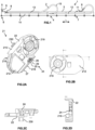
- FIG.2A-2D show various views of an exemplary embodiment of a chain plate 21 according to the invention.
- the body of the chain plate 21 is designed as a molded part 22 made of plastic, which is made from a thermoplastic by injection molding.
- the chain link 21 is plate-shaped and has two broad sides 211, 212 and four narrow sides 213, 214, 215 and 216.
- the broad sides 211, 212 run parallel to the main plane of the chain link 21, in which the longitudinal direction lies and the height direction is perpendicular to the longitudinal direction L.
- the narrow sides 215, 216 run in the longitudinal direction L, the narrow sides 212, 213 run curved essentially in the height direction.
- the chain link 21 also has a cylindrical pin 218 (cf.
- FIG.3B for a receptacle 219 to form an articulated connection with another chain link 21 of the same link strand and a projection 230, in the form of a locking lug, for connection to crossbars.
- FIG.2C shows a section through the projection 230.
- FIG.2D shows a section through recording 219.
- the narrow sides 215, 216 of the chain link 21 have sliding surfaces 27 intended for sliding.
- the sliding surfaces 27 of the narrow sides 216 of the chain plates 21 slide on the sliding surface 47 of the slide rail 14, 44 or on the sliding surfaces 27 the chain plates 21 of the lower run 12.
- the sliding surfaces 27 are exposed to unavoidable wear.
- Due to excessive wear a chain link 21 can be damaged or even broken, which can lead to the breakage of the energy chain 2 and, in the worst case, to the breakage of guided supply lines 9.
- at least a number of chain plates 21 of the energy chain 2 are equipped with a special functional circuit 24 for detecting wear.
- the functional circuit 24 is applied to the body of the chain link 21, i.e. on the plastic molding 22.
- the molded part 22 serves as a circuit carrier for the functional circuit 24.
- the functional circuit 24 has a conductor track structure 25, with a detection area 26 and two contact areas 29.
- the functional circuit 24 is passive and designed as a two-pole and in this example serves for resistive wear detection, namely by conductor interruption. It consists only of the conductor tracks of the detection area 26 and the contact areas 29.
- the detection area 26 is as a section of a conductor track structure, e.g. made of particles containing silver or copper, which were printed onto the prefabricated molded part 22 by 3D printing.
- the detection area 26 has a layer thickness of 5-100 ⁇ m and a conductor track width of 0.5-5mm.
- the contact areas 29 were also printed onto the prefabricated molded part 22 by 3D printing, preferably in one step with the printing of the detection area 26. However, the contact areas 29 have a greater layer thickness, in particular of 250-500 pm.
- the line routing system 1 further comprises a suitable evaluation circuit, not shown, which is connected to the by a contact device with spring contact pins Contact areas 29 of the functional circuit 24 are detachably contacted.
- the functional circuit 24 thus becomes part of the evaluation circuit.
- the wear detection works as follows: due to wear caused by friction, the sliding surface 27 is worn or removed up to a wear limit predetermined in the design, until the conductor track in the detection area 26, which marks the wear limit or runs along the wear limit, is also damaged up to the conductor track interruption . This way the circuit is interrupted and critical wear can be identified. Other measuring principles, such as inductive or capacitive ones, are also possible.
- FIG.3A-3D show a further arrangement of the functional circuit 34 on a chain plate 31.
- the chain plate 31 is a so-called cranked chain plate with a pin 318 on one broad side 311 and a receptacle 320 on the opposite broad side 312, the pin 318 and receptacle 320 of successive chain plates 31 being their articulated connection form.
- the pin 318 and the receptacle 319 have cylindrical areas with sliding surfaces 37. When the two chain plates 31 are pivoted against each other, the adjacent cylindrical surfaces of the pin 318 and the receptacle 319 slide against each other, that is, they are susceptible to wear, especially with high tensile forces, that is, comparatively long or fast-moving energy guide chains 1.
- a functional circuit 34 can also be installed on the sliding surfaces 37 of the articulated connection be arranged, for example in a recess on the surface of the receptacle 319 or the pin 318, at a distance from the corresponding sliding surface 37.
- the structure of the functional circuit 34 can FIG.2 are equivalent to.
- the wear of this sliding surface 37 can be seen as an interruption in the conductor track in the functional circuit 34 be detected.
- FIG. 1 For example, a capacitive, temperature-sensitive or piezo-resistive detection area. They can be used, for example, to detect a wear-related change in the distance or relative arrangement of two overlapping chain plates 31 to one another.
- suitable functional circuits on chain plates in particular a play that occurs in an articulated connection between pin 318 and receptacle 319, or a play between the broad sides 311, 312 of the chain plates 31 in the overlap area can be detected, for example by capacitive or inductive measurement, such as in WO 2019/201482 A1 described.
- the corresponding teaching regarding electrically suitable functional circuits and their arrangement WO 2019/201482 A1 is included here in this respect.
- the narrow sides 313, 314 can also have sliding surfaces.
- an end-side, arcuate projection 321 of a chain plate 31 is accommodated in a corresponding recess or groove 322 of an overlapping chain plate 31.
- a functional circuit 34 can also be provided in this area, for example to monitor that no lateral separation occurs.
- FIG.4 shows a slide rail 14, for example for a guide trough 3 FIG.1 .
- the slide rail 14 is intended to have a sliding surface 47.
- the slide rail 14 is arranged in the operating position in the guide trough 3 so that the sliding surface 47 provides a supporting running surface for the energy chain 2.
- the slide rail 14 is shown in perspective from the underside, which faces away from the sliding surface 47.
- the slide rail 14 has a body which is elongated in the longitudinal direction and which is produced as a molded part 42, preferably from a tribopolymer, by injection molding.
- the body has an open cross section, which is designed as an angle profile.
- the body has a fastening area 410 for fastening to the side parts of the guide channel 3.
- the fastening area 410 has profile elements 411 for this purpose.
- the molded part 42 serves as a circuit carrier for the functional circuit 44.
- the slide rail 14 can also have several functional circuits 44 spaced apart from one another in the longitudinal direction, for wear detection at various points along the slide rail 14 and/or plausibility testing.
- the functional circuits 44 are attached to the surface 48 of the slide rail 14, which faces away from the sliding surface 47.
- the functional circuit 44 is constructed, analogously to the functional circuit 24 described above, essentially from conductor tracks 45 and contact areas 49 and functions according to the resistive principle described above.
- Each functional circuit 44 can be in the structure of the functional circuit 24, for example FIG.2 correspond, with a detection range that is sensitive to the operating parameter.
- a capacitive or inductive principle can also be used additionally or alternatively in the functional circuit 44.
- the functional circuits 24, 34, 44 are off FIG.2-4 include at least one conductor track structure 25, 35, which is directly on the molded part 22, 32 or 42, which serves as a carrier or substrate of the conductor track structure 25, 35 and has comparatively significantly lower conductivity, is applied using a suitable additive manufacturing process.
Landscapes
- Engineering & Computer Science (AREA)
- Chemical & Material Sciences (AREA)
- Manufacturing & Machinery (AREA)
- Materials Engineering (AREA)
- General Engineering & Computer Science (AREA)
- Mechanical Engineering (AREA)
- Composite Materials (AREA)
- Analytical Chemistry (AREA)
- Automation & Control Theory (AREA)
- Electric Cable Arrangement Between Relatively Moving Parts (AREA)
- Devices For Conveying Motion By Means Of Endless Flexible Members (AREA)
- Injection Moulding Of Plastics Or The Like (AREA)
- Sawing (AREA)
- Ropes Or Cables (AREA)
- Insulated Conductors (AREA)
Claims (16)
- Élément de chaîne, en particulier plaque de chaîne (11 ; 21 ; 31), pour une chaîne de guidage d'énergie (2), l'élément de chaîne, en particulier la plaque de chaîne (11 ; 21 ; 31), comprenant une pièce moulée (22 ; 32) fabriquée en matière plastique, fabriquée en particulier par moulage par injection, sur laquelle est disposé un circuit de fonction électrique (24 ; 34) à fonction de capteur destiné à détecter un paramètre de fonctionnement, caractérisé en ce que le circuit de fonction (24 ; 34) comprend au moins une structure à pistes conductrices (25 ; 35) qui est conformée directement sur la pièce moulée (22 ; 32) et est reliée par liaison de matière avec la pièce moulée, la pièce moulée (22 ; 32) constituant elle-même le support de la structure à pistes conductrices (25 ; 35), le circuit de fonction (24 ; 34) étant appliqué en particulier selon un procédé de fabrication additif sur la pièce moulée (22 ; 32) préférentiellement préfabriquée en matière plastique.
- Élément de guidage (14) d'une rainure de guidage (3) d'un système de guidage pour lignes (1) avec une chaîne de guidage d'énergie (2), en particulier une glissière ou une languette de glissement, l'élément de guidage (14) comprenant une pièce moulée (42) fabriquée en matière plastique, en particulier par moulage par injection, qui présente une surface de glissement (47) pour une chaîne de guidage d'énergie (2) guidée dans la rainure de guidage (3), caractérisé en ce qu'est disposé sur la pièce moulée (42) au moins un circuit de fonction électrique (44) à fonction de capteur destiné à détecter un paramètre de fonctionnement, comprenant au moins une structure à pistes conductrices (45) qui est conformée directement sur la pièce moulée (42) et est reliée par liaison de matière avec la pièce moulée, la pièce moulée (22 ; 32) constituant elle-même le support de la structure à pistes conductrices (25 ; 35), le circuit de fonction (44) étant appliqué en particulier selon un procédé de fabrication additif sur la pièce moulée (42) préférentiellement préfabriquée en matière plastique.
- Dispositif (11 ; 21 ; 31 ; 14) selon la revendication 1 ou 2, caractérisé en ce que la pièce moulée (22 ; 32 ; 42) est préfabriquée et sert de support de circuit, en particulier de support de circuit moulé par injection, pour le circuit de fonction (24 ; 34 ; 44).
- Dispositif (11 ; 21 ; 31 ; 14) selon l'une des revendications précédentes, caractérisé en ce que le circuit de fonction (24 ; 34 ; 44) comprend une zone de détection (26 ; 36 ; 46) sensible relativement au paramètre de fonctionnement, la zone de détection s'étendant préférentiellement au moins partiellement le long d'une limite d'usure à détecter, de sorte qu'un dépassement de la limite d'usure est détectable par le circuit de fonction.
- Plaque de chaîne (11 ; 21 ; 31) selon la revendication 1, la pièce moulée (22 ; 32) présentant au niveau d'un chant de la plaque de chaîne une surface de glissement (27 ; 37) destinée à glisser sur une autre plaque de chaîne (11 ; 21 ; 31) et/ou sur une glissière (14) d'une rainure de guidage (3).
- Dispositif selon les revendications 4 et 5, caractérisé en ce que la zone de détection présente, dans un état neuf du dispositif, un écart prédéfini avec la surface de glissement, est prévue en particulier au niveau d'une surface opposée à la surface de glissement.
- Dispositif (11 ; 21 ; 31 ; 14) selon l'une des revendications précédentes, caractérisé en ce que le circuit de fonction (24 ; 34 ; 44) est appliqué sur une surface (28 ; 38 ; 48) de la pièce moulée (22 ; 32 ; 42), est en particulier intégré dans la surface (28 ; 38 ; 48).
- Dispositif selon l'une des revendications précédentes, caractérisé en ce que la pièce moulée présente un creux préfabriqué (28), dans lequel le circuit de fonction est logé au moins partiellement ou complètement.
- Dispositif selon l'une des revendications précédentes, caractérisé en ce que la structure à pistes conductrices (25 ; 35) est fabriquée dans un matériau qui présente une conductivité nettement plus élevée que la matière plastique de la pièce moulée, en particulier dans un matériau contenant une part d'argent, de cuivre et/ou de carbone.
- Dispositif selon l'une des revendications précédentes, caractérisé en ce que la structure à pistes conductrices (25 ; 35) comprend des pistes conductrices qui sont appliquées de manière additive selon un procédé AM et présentent une première épaisseur de couche, préférentiellement une première épaisseur de couche de ≤200 µm, en particulier préférentiellement de ≤100 µm pour une largeur de conducteur de 0,5-5 mm ; ainsi que des zones de contact (29 ; 39 ; 49) destinées à une mise en contact amovible, qui sont appliquées de manière additive selon le même procédé AM et qui présentent une deuxième épaisseur de couche qui est nettement supérieure à la première épaisseur de couche, préférentiellement une deuxième épaisseur de couche de ≥200 µm, en particulier dans la plage de 250-500 µm, le circuit de fonction étant préférentiellement de conception passive et en particulier composé de pistes conductrices et de zones de contact et servant à la détection résistive de l'usure, en particulier par une coupure des conducteurs.
- Dispositif selon l'une des revendications 1 à 10, caractérisé en ce que le circuit de fonction comprend une zone de détection inductive, capacitive, thermosensible ou piézorésistive, en particulier une zone de détection destinée à détecter une modification de la position du dispositif par rapport à un autre dispositif en mouvement par rapport au dispositif.
- Dispositif selon l'une des revendications précédentes, en particulier élément de guidage selon la revendication 2, caractérisé en ce que la pièce moulée comprend un tribopolymère, est en particulier préfabriquée dans un tribopolymère qui présente un polymère de base et des lubrifiants solides et préférentiellement des fibres de renforcement et/ou des charges.
- Élément de guidage selon la revendication 2, l'élément de guidage étant une glissière pour une rainure de guidage d'une chaîne de guidage de l'énergie, étant conformé avec un corps allongé dans un sens longitudinal et une section ouverte perpendiculairement au sens longitudinal et en particulier conçu comme profilé angulaire, la glissière présentant préférentiellement une pluralité de circuits de fonction, qui sont espacés entre eux dans un sens longitudinal de l'élément de guidage, la glissière présentant en particulier préférentiellement une zone de fixation (410) pour la fixation sur une rainure de guidage (3), la zone de fixation (410) présentant des éléments profilés (411) pour la fixation sur un élément latéral de la rainure de guidage.
- Plaque de chaîne (11 ; 21 ; 31) selon l'une des revendications 1 ou 3 à 12, avec deux faces (211, 212 ; 311, 312) et quatre chats (213, 214, 215, 216 ; 313, 314, 315, 316), au moins un des chants (216 ; 316) étant conformé pour glisser sur une glissière (14) ou des chants (216 ; 316) d'autres plaques de chaîne (11 ; 21 ;31), et/ou au moins une des faces (211, 212 ; 311, 312) présentant au moins un pivot (218 ; 318) et/ou au moins un logement correspondant (220 ; 320) en vue de constituer des liaisons articulées avec chacune un axe de pivotement nominal entre des plaques de chaîne successives (11 ; 21 ; 31), caractérisé en ce que le circuit de fonction (24 ; 34) est fixé ou appliqué par impression sur le au moins un pivot (218 ; 318) et/ou sur le au moins un logement (220 ; 320) et/ou sur au moins un des chants (216 ; 316).
- Système (1) avec une chaîne de guidage de l'énergie (2), en particulier pour de longs déplacements, pour le guidage dynamique de conduites d'approvisionnement (9) entre deux points de raccordement (6, 7) mobiles l'un par rapport à l'autre, caractérisé en ce que la chaîne de guidage de l'énergie (2) comprend au moins une plaque de chaîne (11 ; 21 ; 31) selon l'une des revendications 1 ou 3 à 12 et/ou que le système (1) comprend une rainure de guidage (3) pour une chaîne de guidage de l'énergie (2) avec au moins un élément de guidage (14) selon l'une des revendications 2 à 4 ou 6 à 13, le système (1) comprenant en outre un circuit d'évaluation, lequel est relié au circuit de fonction (24 ; 34 ; 44) par technique de signalisation, en particulier de manière amovible, le système (1) présentant préférentiellement un dispositif de contact relié au circuit d'évaluation, en particulier avec des tiges de contact à ressort pour la mise en contact amovible du circuit d'évaluation avec le circuit de fonction (24 ; 34 ; 44).
- Système (1) selon la revendication 15, caractérisé en ce que le circuit d'évaluation évalue au moins un paramètre de fonctionnement sur la base du(des) circuit(s) de fonction (24 ; 34 ; 44) et comprend un module de communication qui est configuré pour la transmission d'un résultat d'évaluation à un système de surveillance de niveau supérieur.
Applications Claiming Priority (2)
| Application Number | Priority Date | Filing Date | Title |
|---|---|---|---|
| DE202020100143.4U DE202020100143U1 (de) | 2020-01-10 | 2020-01-10 | Kunststoff-Bauteile für Energieführungsketten mit integrierter Sensorik |
| PCT/EP2021/050202 WO2021140162A1 (fr) | 2020-01-10 | 2021-01-07 | Composants en plastique pour supports de câbles avec système de capteur intégré |
Publications (3)
| Publication Number | Publication Date |
|---|---|
| EP4088043A1 EP4088043A1 (fr) | 2022-11-16 |
| EP4088043C0 EP4088043C0 (fr) | 2024-03-06 |
| EP4088043B1 true EP4088043B1 (fr) | 2024-03-06 |
Family
ID=69781742
Family Applications (1)
| Application Number | Title | Priority Date | Filing Date |
|---|---|---|---|
| EP21700380.5A Active EP4088043B1 (fr) | 2020-01-10 | 2021-01-07 | Composants en plastique pour supports de câbles avec système de capteur intégré |
Country Status (12)
| Country | Link |
|---|---|
| US (1) | US20230038431A1 (fr) |
| EP (1) | EP4088043B1 (fr) |
| JP (1) | JP2023514666A (fr) |
| KR (1) | KR20220117343A (fr) |
| CN (1) | CN115066569A (fr) |
| AU (1) | AU2021206014A1 (fr) |
| BR (1) | BR112022011931A2 (fr) |
| CA (1) | CA3165396A1 (fr) |
| DE (1) | DE202020100143U1 (fr) |
| ES (1) | ES2981054T3 (fr) |
| TW (1) | TWI875921B (fr) |
| WO (1) | WO2021140162A1 (fr) |
Families Citing this family (2)
| Publication number | Priority date | Publication date | Assignee | Title |
|---|---|---|---|---|
| JP7786735B2 (ja) * | 2020-05-27 | 2025-12-16 | イグス ゲゼルシャフト ミット ベシュレンクター ハフトゥング | フレキシブルジョイントコネクタを有するエネルギーガイドチェーン、サイドプレート、及びそのためのジョイントコネクタ |
| DE102022125087A1 (de) | 2022-09-29 | 2024-04-04 | Schaeffler Technologies AG & Co. KG | Energiezuführungsvorrichtung und Linearsystem mit einer Energiezuführungsvorrichtung |
Family Cites Families (18)
| Publication number | Priority date | Publication date | Assignee | Title |
|---|---|---|---|---|
| US3810147A (en) * | 1971-12-30 | 1974-05-07 | G Lichtblau | Electronic security system |
| US6424263B1 (en) * | 2000-12-01 | 2002-07-23 | Microchip Technology Incorporated | Radio frequency identification tag on a single layer substrate |
| WO2004090375A1 (fr) * | 2003-04-04 | 2004-10-21 | Igus Gmbh | Systeme de surveillance pour le fonctionnement d'au moins une chaine de guidage d'elements de transport d'energie |
| US7209039B2 (en) * | 2003-05-08 | 2007-04-24 | Illinois Tool Works Inc. | Decorative surface covering with embedded RF antenna and RF shield and method for making the same |
| DE10346486B4 (de) * | 2003-10-02 | 2012-08-02 | Murrplastik Systemtechnik Gmbh | Energieführungskette |
| JP4963308B2 (ja) * | 2008-11-20 | 2012-06-27 | 株式会社椿本チエイン | ケーブル保護案内装置用ガイドレール |
| MX2018008997A (es) * | 2016-01-28 | 2018-11-19 | Igus Gmbh | Dispositivo de guia de linea con deteccion electrica de deterioro y circuito de radio para el mismo. |
| DE202016000501U1 (de) * | 2016-01-28 | 2017-03-02 | Igus Gmbh | Energieführungskette oder Leitungsführungseinrichtung mit elektrotechnischer Verschleißerkennung |
| DE202016102133U1 (de) * | 2016-04-21 | 2017-05-23 | Igus Gmbh | Gleitlager, Kunststoffgleitelement, System und Verwendung zur Verschleißerkennung |
| DE102016006061A1 (de) * | 2016-05-19 | 2017-11-23 | Murrplastik Systemtechnik Gmbh | Energieführungskette |
| DE202016107317U1 (de) * | 2016-12-23 | 2017-03-27 | Igus Gmbh | Systeme zur Überwachung des Betriebs einer Energieführungskette |
| WO2019102522A1 (fr) * | 2017-11-21 | 2019-05-31 | 株式会社Fuji | Procédé de production de dispositif électronique multicouche tridimensionnel, et dispositif électronique multicouche tridimensionnel |
| DE202018100339U1 (de) * | 2018-01-22 | 2019-04-24 | Tsubaki Kabelschlepp GmbH | Energieführungsvorrichtung mit einem Verschleißdetektor |
| DE202018101942U1 (de) * | 2018-04-10 | 2018-05-03 | Igus Gmbh | System zur Sicherung des Verlaufs einer Leitungsführungseinrichtung und Führungsrinne hierfür |
| DE202018102239U1 (de) | 2018-04-21 | 2019-05-23 | Igus Gmbh | Energieführungskette mit Verschleißerkennung |
| DE202018105755U1 (de) * | 2018-10-08 | 2019-11-11 | Igus Gmbh | Kunststoff-Gleitelement mit Sensorfunktion, insbesondere mit Verschleißerkennung |
| DE202019101776U1 (de) * | 2019-03-28 | 2019-12-04 | Igus Gmbh | Kunststoff-Gleitelement mit Sensorfunktion, insbesondere mit Verschleißerkennung |
| DE202019104826U1 (de) * | 2019-09-02 | 2019-09-26 | Tsubaki Kabelschlepp GmbH | Vorrichtung umfassend eine Energieführungskette und eine Gleitauflage |
-
2020
- 2020-01-10 DE DE202020100143.4U patent/DE202020100143U1/de active Active
-
2021
- 2021-01-07 AU AU2021206014A patent/AU2021206014A1/en not_active Abandoned
- 2021-01-07 CN CN202180013536.5A patent/CN115066569A/zh active Pending
- 2021-01-07 KR KR1020227027376A patent/KR20220117343A/ko not_active Ceased
- 2021-01-07 BR BR112022011931A patent/BR112022011931A2/pt not_active Application Discontinuation
- 2021-01-07 JP JP2022541958A patent/JP2023514666A/ja active Pending
- 2021-01-07 EP EP21700380.5A patent/EP4088043B1/fr active Active
- 2021-01-07 WO PCT/EP2021/050202 patent/WO2021140162A1/fr not_active Ceased
- 2021-01-07 ES ES21700380T patent/ES2981054T3/es active Active
- 2021-01-07 US US17/758,606 patent/US20230038431A1/en not_active Abandoned
- 2021-01-07 CA CA3165396A patent/CA3165396A1/fr active Pending
- 2021-01-08 TW TW110100769A patent/TWI875921B/zh active
Also Published As
| Publication number | Publication date |
|---|---|
| ES2981054T3 (es) | 2024-10-07 |
| US20230038431A1 (en) | 2023-02-09 |
| JP2023514666A (ja) | 2023-04-07 |
| CN115066569A (zh) | 2022-09-16 |
| EP4088043C0 (fr) | 2024-03-06 |
| AU2021206014A1 (en) | 2022-08-25 |
| EP4088043A1 (fr) | 2022-11-16 |
| KR20220117343A (ko) | 2022-08-23 |
| CA3165396A1 (fr) | 2021-07-15 |
| DE202020100143U1 (de) | 2020-02-24 |
| WO2021140162A1 (fr) | 2021-07-15 |
| TWI875921B (zh) | 2025-03-11 |
| TW202132702A (zh) | 2021-09-01 |
| BR112022011931A2 (pt) | 2022-09-06 |
Similar Documents
| Publication | Publication Date | Title |
|---|---|---|
| EP3864309B1 (fr) | Élément glissant en plastique avec fonction de capteur, notamment avec détection d'usure | |
| DE19600295C2 (de) | Kapazitive Elektrodenschieblehre | |
| DE202019101776U1 (de) | Kunststoff-Gleitelement mit Sensorfunktion, insbesondere mit Verschleißerkennung | |
| DE102016109117B4 (de) | Tragbares Sensorsystem mit einem Kleidungsstück und einem Elektronikmodul, Kleidungsstück für ein tragbares Sensorsystem sowie Elektronikmodul für ein tragbares Sensorsystem | |
| EP2306157B1 (fr) | Dispositif de mesure de longueur | |
| DE102009043200A1 (de) | Verfahren zum Verschweißen eines Kunststoffgehäuses | |
| EP3552463B1 (fr) | Assemblage de cartes de circuits imprimés et son procédé de fabrication | |
| EP3584934B1 (fr) | Unité de détection pouvant être insérée | |
| WO2021140162A1 (fr) | Composants en plastique pour supports de câbles avec système de capteur intégré | |
| DE202018105755U1 (de) | Kunststoff-Gleitelement mit Sensorfunktion, insbesondere mit Verschleißerkennung | |
| WO2013182466A1 (fr) | Ensemble capteur capacitif pour actionner une ouverture de porte au niveau d'un véhicule automobile | |
| EP4005697B1 (fr) | Dispositif et procede pour determiner la temperature dans une paroi laterale d'un moule de fonderie | |
| EP3513201B1 (fr) | Broche de contact, notamment broche de contact à ressort | |
| DE102007008729B4 (de) | Abtastelement zur Erfassung eines Verschleißwegs eines Bremsbelags | |
| EP1208356A1 (fr) | Roulement lineaire comportant une unite servant a effectuer une mesure | |
| DE10326141B4 (de) | Elektromechanische Baugruppe | |
| EP1151257A1 (fr) | Capteur et son procede de fabrication | |
| WO2006060972A1 (fr) | Module electromecanique | |
| EP3988386B1 (fr) | Dispositif de réception de rail conducteur | |
| EP4259389B1 (fr) | Dispositif de securite antichoc pour robot | |
| DE19927108A1 (de) | Verfahren zur Herstellung von Sensoren sowie Sensor, insbesondere Temperatursensor | |
| EP4386223A1 (fr) | Élément coulissant doté d'un moyen de détection d'usure | |
| EP0614780B1 (fr) | Détecteur de bris pour pièce de frottement | |
| EP3751710A1 (fr) | Dispositif électrique | |
| DE2751674A1 (de) | Bremsbacke fuer scheibenbremsen |
Legal Events
| Date | Code | Title | Description |
|---|---|---|---|
| STAA | Information on the status of an ep patent application or granted ep patent |
Free format text: STATUS: UNKNOWN |
|
| STAA | Information on the status of an ep patent application or granted ep patent |
Free format text: STATUS: THE INTERNATIONAL PUBLICATION HAS BEEN MADE |
|
| PUAI | Public reference made under article 153(3) epc to a published international application that has entered the european phase |
Free format text: ORIGINAL CODE: 0009012 |
|
| STAA | Information on the status of an ep patent application or granted ep patent |
Free format text: STATUS: REQUEST FOR EXAMINATION WAS MADE |
|
| 17P | Request for examination filed |
Effective date: 20220801 |
|
| AK | Designated contracting states |
Kind code of ref document: A1 Designated state(s): AL AT BE BG CH CY CZ DE DK EE ES FI FR GB GR HR HU IE IS IT LI LT LU LV MC MK MT NL NO PL PT RO RS SE SI SK SM TR |
|
| DAV | Request for validation of the european patent (deleted) | ||
| DAX | Request for extension of the european patent (deleted) | ||
| P01 | Opt-out of the competence of the unified patent court (upc) registered |
Effective date: 20230526 |
|
| GRAP | Despatch of communication of intention to grant a patent |
Free format text: ORIGINAL CODE: EPIDOSNIGR1 |
|
| STAA | Information on the status of an ep patent application or granted ep patent |
Free format text: STATUS: GRANT OF PATENT IS INTENDED |
|
| INTG | Intention to grant announced |
Effective date: 20230816 |
|
| GRAS | Grant fee paid |
Free format text: ORIGINAL CODE: EPIDOSNIGR3 |
|
| GRAA | (expected) grant |
Free format text: ORIGINAL CODE: 0009210 |
|
| STAA | Information on the status of an ep patent application or granted ep patent |
Free format text: STATUS: THE PATENT HAS BEEN GRANTED |
|
| AK | Designated contracting states |
Kind code of ref document: B1 Designated state(s): AL AT BE BG CH CY CZ DE DK EE ES FI FR GB GR HR HU IE IS IT LI LT LU LV MC MK MT NL NO PL PT RO RS SE SI SK SM TR |
|
| REG | Reference to a national code |
Ref country code: CH Ref legal event code: EP |
|
| REG | Reference to a national code |
Ref country code: DE Ref legal event code: R096 Ref document number: 502021002901 Country of ref document: DE |
|
| REG | Reference to a national code |
Ref country code: IE Ref legal event code: FG4D Free format text: LANGUAGE OF EP DOCUMENT: GERMAN |
|
| U01 | Request for unitary effect filed |
Effective date: 20240402 |
|
| U07 | Unitary effect registered |
Designated state(s): AT BE BG DE DK EE FI FR IT LT LU LV MT NL PT SE SI Effective date: 20240411 |
|
| P04 | Withdrawal of opt-out of the competence of the unified patent court (upc) registered |
Effective date: 20240412 |
|
| PG25 | Lapsed in a contracting state [announced via postgrant information from national office to epo] |
Ref country code: GR Free format text: LAPSE BECAUSE OF FAILURE TO SUBMIT A TRANSLATION OF THE DESCRIPTION OR TO PAY THE FEE WITHIN THE PRESCRIBED TIME-LIMIT Effective date: 20240607 |
|
| PG25 | Lapsed in a contracting state [announced via postgrant information from national office to epo] |
Ref country code: HR Free format text: LAPSE BECAUSE OF FAILURE TO SUBMIT A TRANSLATION OF THE DESCRIPTION OR TO PAY THE FEE WITHIN THE PRESCRIBED TIME-LIMIT Effective date: 20240306 Ref country code: RS Free format text: LAPSE BECAUSE OF FAILURE TO SUBMIT A TRANSLATION OF THE DESCRIPTION OR TO PAY THE FEE WITHIN THE PRESCRIBED TIME-LIMIT Effective date: 20240606 |
|
| PG25 | Lapsed in a contracting state [announced via postgrant information from national office to epo] |
Ref country code: RS Free format text: LAPSE BECAUSE OF FAILURE TO SUBMIT A TRANSLATION OF THE DESCRIPTION OR TO PAY THE FEE WITHIN THE PRESCRIBED TIME-LIMIT Effective date: 20240606 Ref country code: NO Free format text: LAPSE BECAUSE OF FAILURE TO SUBMIT A TRANSLATION OF THE DESCRIPTION OR TO PAY THE FEE WITHIN THE PRESCRIBED TIME-LIMIT Effective date: 20240606 Ref country code: HR Free format text: LAPSE BECAUSE OF FAILURE TO SUBMIT A TRANSLATION OF THE DESCRIPTION OR TO PAY THE FEE WITHIN THE PRESCRIBED TIME-LIMIT Effective date: 20240306 Ref country code: GR Free format text: LAPSE BECAUSE OF FAILURE TO SUBMIT A TRANSLATION OF THE DESCRIPTION OR TO PAY THE FEE WITHIN THE PRESCRIBED TIME-LIMIT Effective date: 20240607 |
|
| PG25 | Lapsed in a contracting state [announced via postgrant information from national office to epo] |
Ref country code: IS Free format text: LAPSE BECAUSE OF FAILURE TO SUBMIT A TRANSLATION OF THE DESCRIPTION OR TO PAY THE FEE WITHIN THE PRESCRIBED TIME-LIMIT Effective date: 20240706 |
|
| REG | Reference to a national code |
Ref country code: ES Ref legal event code: FG2A Ref document number: 2981054 Country of ref document: ES Kind code of ref document: T3 Effective date: 20241007 |
|
| PG25 | Lapsed in a contracting state [announced via postgrant information from national office to epo] |
Ref country code: SM Free format text: LAPSE BECAUSE OF FAILURE TO SUBMIT A TRANSLATION OF THE DESCRIPTION OR TO PAY THE FEE WITHIN THE PRESCRIBED TIME-LIMIT Effective date: 20240306 |
|
| PG25 | Lapsed in a contracting state [announced via postgrant information from national office to epo] |
Ref country code: CZ Free format text: LAPSE BECAUSE OF FAILURE TO SUBMIT A TRANSLATION OF THE DESCRIPTION OR TO PAY THE FEE WITHIN THE PRESCRIBED TIME-LIMIT Effective date: 20240306 |
|
| PG25 | Lapsed in a contracting state [announced via postgrant information from national office to epo] |
Ref country code: PL Free format text: LAPSE BECAUSE OF FAILURE TO SUBMIT A TRANSLATION OF THE DESCRIPTION OR TO PAY THE FEE WITHIN THE PRESCRIBED TIME-LIMIT Effective date: 20240306 |
|
| PG25 | Lapsed in a contracting state [announced via postgrant information from national office to epo] |
Ref country code: SK Free format text: LAPSE BECAUSE OF FAILURE TO SUBMIT A TRANSLATION OF THE DESCRIPTION OR TO PAY THE FEE WITHIN THE PRESCRIBED TIME-LIMIT Effective date: 20240306 |
|
| PG25 | Lapsed in a contracting state [announced via postgrant information from national office to epo] |
Ref country code: SM Free format text: LAPSE BECAUSE OF FAILURE TO SUBMIT A TRANSLATION OF THE DESCRIPTION OR TO PAY THE FEE WITHIN THE PRESCRIBED TIME-LIMIT Effective date: 20240306 Ref country code: SK Free format text: LAPSE BECAUSE OF FAILURE TO SUBMIT A TRANSLATION OF THE DESCRIPTION OR TO PAY THE FEE WITHIN THE PRESCRIBED TIME-LIMIT Effective date: 20240306 Ref country code: RO Free format text: LAPSE BECAUSE OF FAILURE TO SUBMIT A TRANSLATION OF THE DESCRIPTION OR TO PAY THE FEE WITHIN THE PRESCRIBED TIME-LIMIT Effective date: 20240306 Ref country code: PL Free format text: LAPSE BECAUSE OF FAILURE TO SUBMIT A TRANSLATION OF THE DESCRIPTION OR TO PAY THE FEE WITHIN THE PRESCRIBED TIME-LIMIT Effective date: 20240306 Ref country code: IS Free format text: LAPSE BECAUSE OF FAILURE TO SUBMIT A TRANSLATION OF THE DESCRIPTION OR TO PAY THE FEE WITHIN THE PRESCRIBED TIME-LIMIT Effective date: 20240706 Ref country code: CZ Free format text: LAPSE BECAUSE OF FAILURE TO SUBMIT A TRANSLATION OF THE DESCRIPTION OR TO PAY THE FEE WITHIN THE PRESCRIBED TIME-LIMIT Effective date: 20240306 |
|
| REG | Reference to a national code |
Ref country code: DE Ref legal event code: R097 Ref document number: 502021002901 Country of ref document: DE |
|
| PLBE | No opposition filed within time limit |
Free format text: ORIGINAL CODE: 0009261 |
|
| STAA | Information on the status of an ep patent application or granted ep patent |
Free format text: STATUS: NO OPPOSITION FILED WITHIN TIME LIMIT |
|
| 26N | No opposition filed |
Effective date: 20241209 |
|
| U20 | Renewal fee for the european patent with unitary effect paid |
Year of fee payment: 5 Effective date: 20250123 |
|
| PG25 | Lapsed in a contracting state [announced via postgrant information from national office to epo] |
Ref country code: MC Free format text: LAPSE BECAUSE OF FAILURE TO SUBMIT A TRANSLATION OF THE DESCRIPTION OR TO PAY THE FEE WITHIN THE PRESCRIBED TIME-LIMIT Effective date: 20240306 |
|
| PG25 | Lapsed in a contracting state [announced via postgrant information from national office to epo] |
Ref country code: IE Free format text: LAPSE BECAUSE OF NON-PAYMENT OF DUE FEES Effective date: 20250107 |
|
| REG | Reference to a national code |
Ref country code: CH Ref legal event code: U11 Free format text: ST27 STATUS EVENT CODE: U-0-0-U10-U11 (AS PROVIDED BY THE NATIONAL OFFICE) Effective date: 20260201 |
|
| U1H | Name or address of the proprietor changed after the registration of the unitary effect |
Owner name: IGUS SE & CO. KG; DE |
|
| U20 | Renewal fee for the european patent with unitary effect paid |
Year of fee payment: 6 Effective date: 20260126 |
|
| PGFP | Annual fee paid to national office [announced via postgrant information from national office to epo] |
Ref country code: GB Payment date: 20260122 Year of fee payment: 6 |
|
| PGFP | Annual fee paid to national office [announced via postgrant information from national office to epo] |
Ref country code: ES Payment date: 20260217 Year of fee payment: 6 |
|
| PGFP | Annual fee paid to national office [announced via postgrant information from national office to epo] |
Ref country code: CH Payment date: 20260201 Year of fee payment: 6 |
|
| PG25 | Lapsed in a contracting state [announced via postgrant information from national office to epo] |
Ref country code: CY Free format text: LAPSE BECAUSE OF FAILURE TO SUBMIT A TRANSLATION OF THE DESCRIPTION OR TO PAY THE FEE WITHIN THE PRESCRIBED TIME-LIMIT Effective date: 20240306 |
|
| PG25 | Lapsed in a contracting state [announced via postgrant information from national office to epo] |
Ref country code: TR Free format text: LAPSE BECAUSE OF FAILURE TO SUBMIT A TRANSLATION OF THE DESCRIPTION OR TO PAY THE FEE WITHIN THE PRESCRIBED TIME-LIMIT Effective date: 20240306 |