EP4089043B1 - Système de câble grue - Google Patents
Système de câble grue Download PDFInfo
- Publication number
- EP4089043B1 EP4089043B1 EP22173012.0A EP22173012A EP4089043B1 EP 4089043 B1 EP4089043 B1 EP 4089043B1 EP 22173012 A EP22173012 A EP 22173012A EP 4089043 B1 EP4089043 B1 EP 4089043B1
- Authority
- EP
- European Patent Office
- Prior art keywords
- cable
- energy storage
- crane system
- electric motor
- generator
- Prior art date
- Legal status (The legal status is an assumption and is not a legal conclusion. Google has not performed a legal analysis and makes no representation as to the accuracy of the status listed.)
- Active
Links
Images


Classifications
-
- B—PERFORMING OPERATIONS; TRANSPORTING
- B66—HOISTING; LIFTING; HAULING
- B66C—CRANES; LOAD-ENGAGING ELEMENTS OR DEVICES FOR CRANES, CAPSTANS, WINCHES, OR TACKLES
- B66C21/00—Cable cranes, i.e. comprising hoisting devices running on aerial cable-ways
-
- B—PERFORMING OPERATIONS; TRANSPORTING
- B66—HOISTING; LIFTING; HAULING
- B66C—CRANES; LOAD-ENGAGING ELEMENTS OR DEVICES FOR CRANES, CAPSTANS, WINCHES, OR TACKLES
- B66C21/00—Cable cranes, i.e. comprising hoisting devices running on aerial cable-ways
- B66C21/04—Cable cranes, i.e. comprising hoisting devices running on aerial cable-ways with cable-ways supported at one end or both ends on bodily movable framework, e.g. framework mounted on rail track
-
- B—PERFORMING OPERATIONS; TRANSPORTING
- B66—HOISTING; LIFTING; HAULING
- B66C—CRANES; LOAD-ENGAGING ELEMENTS OR DEVICES FOR CRANES, CAPSTANS, WINCHES, OR TACKLES
- B66C13/00—Other constructional features or details
- B66C13/18—Control systems or devices
- B66C13/22—Control systems or devices for electric drives
- B66C13/23—Circuits for controlling the lowering of the load
- B66C13/26—Circuits for controlling the lowering of the load by AC motors
- B66C13/28—Circuits for controlling the lowering of the load by AC motors utilising regenerative braking for controlling descent of heavy loads and having means for preventing rotation of motor in the hoisting direction when load is released
Definitions
- the invention relates to a cable crane system with at least one carriage, at least one supporting cable on which the at least one carriage is or can be arranged to be movable, at least one traction cable (circulating cable) which is arranged on the at least one carriage, and at least one cable winch device for moving the at least one carriage, by means of which the at least one traction cable can be wound up and unwound.
- a cable crane system with at least one carriage, at least one supporting cable on which the at least one carriage is or can be arranged to be movable, at least one traction cable (circulating cable) which is arranged on the at least one carriage, and at least one cable winch device for moving the at least one carriage, by means of which the at least one traction cable can be wound up and unwound.
- the felled trees are transported from a mountain or slope to a valley using a cable crane system.
- One or more felled trees are attached to the carriage, which then travels down the valley along the support cable, taking advantage of gravity. In the valley, the felled trees can be further processed and/or transported away.
- the cable winch and the traction cable are provided for this purpose.
- the traction cable is designed as a circulating cable. This means that the traction cable is attached to the carriage and is redirected at the highest point of the cable crane system (mountain or slope location) and returned to the The winch is guided by a cable winch device. By winding up the traction cable using the winch device, the carriage can be guided back to the mountain or slope position.
- an internal combustion engine is usually used to drive the winch device. This is associated with several disadvantages.
- the WO 2018/065090 A1 discloses a cable crane system with at least one carriage, at least one supporting cable on which the at least one carriage is or can be arranged to be movable, at least one cable winch device for moving the at least one carriage, wherein the at least one cable winch device comprises at least one electric motor for operating the at least one cable winch device, and wherein the at least one electric motor can be operated as a generator, wherein the at least one electric motor operated as a generator can be driven by a travel movement of the at least one carriage, wherein the at least one carriage comprises at least one hoist winch and a drive unit for driving the at least one hoist winch, and a further energy store for feeding the drive unit, wherein the further energy store can be charged via a generator traveling with the at least one carriage.
- the cable winch device is initially intended to include at least one electric motor for operating the cable winch device.
- An electric motor also offers other advantages, such as the high torque available right from the start. Often, a tree is attached to the carriage and then lifted or moved from its storage location by moving the carriage. Particularly when trees have been stored for a long time, they may have grown into the ground or sunk. In these cases, this torque is advantageous for easily moving the trees.
- a battery-powered power supply is also not practical. Either the battery would have to be extremely large to provide sufficient energy for logging operations lasting several days, which would be uneconomical, as would the cost of transporting such a battery to the site. Or the battery would have to be recharged after each workday. which would require it to be transported to a suitable charging station.
- the carriage complete with the felled trees, descends along the support cable due to gravity.
- the traction cable is unwound via the deflection.
- at least one electric motor can be operated as a generator and powered by the unwinding. This allows the potential energy of the felled trees to be converted into usable electrical energy.
- the carriage comprises at least two rollers, via which the carriage can be arranged displaceably on a support cable, at least one hoist winch and a drive unit for driving the at least one hoist winch, and a further energy storage device for supplying the drive unit, wherein the further energy storage device can be charged via a generator traveling with the carriage.
- the at least one cable winch device comprises at least one cable drum, onto which at least one traction rope can be wound up and unwound.
- the at least one cable drum can be driven by the at least one electric motor and/or the at least one electric motor operated as a generator can be driven by the at least one cable drum when the traction cable is unwound or wound up.
- the cable crane system can comprise at least one energy storage device for supplying the at least one electric motor, wherein the at least one energy storage device can be charged via the at least one electric motor operated as a generator.
- the at least one energy storage device allows the energy generated by the electric motor operating as a generator to be temporarily stored until needed, for example, to operate the at least one electric motor. Since the at least one energy storage device is charged every time the carriage descends a hill, it can be significantly smaller than if it could only be charged once a day, for example.
- the energy storage device can be designed as an accumulator. Since excessive capacities are not required and the battery is essentially stationary, a cost-effective lead-acid battery or similar can be used.
- a cost-effective lead-acid battery or similar can be used.
- other battery technologies or other energy storage devices, such as physical energy storage, are also conceivable.
- the cable crane system has a battery management system (BMS) for monitoring, controlling and protecting the at least one energy storage device.
- BMS battery management system
- the energy storage device is charged during the (quite numerous) travel movements of the carriage and/or unwinding operations of the hoist winch and enables energy-autonomous use of the carriage during pulling or load picking up with the hoist winch.
- the at least one carriage and/or the at least one cable winch device can preferably have a radio module for receiving and/or transmitting data from or to the remote control.
- this data connection can be used for a variety of purposes.
- control unit will be arranged on or in the at least one cable winch device, since space requirements and weight play a lesser role in the at least one stationary cable winch device than, for example, in the carriage.
- the at least one carriage has a further control unit for controlling and/or regulating the carriage, in particular the drive unit, the generator and/or the further energy storage device.
- control and/or regulation processes that only affect the carriage can be processed more quickly, as data does not first have to be transferred between the carriage and the control unit, then processed at the control unit, and finally sent back to the carriage.
- the electric motor If the electric motor is operated as a generator, it also acts as a brake, which slows down the movement of the carriage by braking the cable drum.
- the at least one cable winch device has at least one braking device.
- This braking device serves to brake at least one carriage in the event that the braking power via at least one electric motor operated as a generator is too low or all energy storage devices are full and therefore no more braking power can be achieved.
- a user interface may also be provided, preferably on the cable winch device and/or on the remote control.
- This user interface can display a wide variety of data, such as the charge level of the energy storage device and/or the additional energy storage device, the energy consumption of at least one external consumer, etc.
- a warning device is also conceivable. If both energy storage units are fully charged, this warning device can warn the user that energy will be converted into unusable energy (heat energy during braking) during the next descent.
- the cable crane system has an automatic targeting system.
- an operator a so-called winch operator, is required to brake the carriage before each support to ensure that the supports are safely crossed.
- the cable crane system in a transport state has maximum dimensions (L x W x H) of 5.8 m x 2.3 m x 2.3 m.
- the cable crane system remains at least partially on a transport vehicle, for example a truck or trailer, in an operating state.
- a tilting mast cable device and at least one cable winch device can be mounted stationary on the transport vehicle. This facilitates rapid assembly and disassembly of the cable crane system.
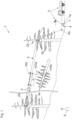
- the Figure 1 shows a schematic representation of a cable crane system 1.
- a supporting cable 2 is visible, with a carriage 100 mounted on the supporting cable 2 via rollers 102.
- the rollers 102 are arranged on support arms 112.
- the support cable 2 is tensioned between two trees via bearing rollers 2a and then guyed to the ground (not visible).
- the support cable 2 can also be tensioned, for example, between a tree and a tilting mast cable device, between two tilting mast cable devices, or between other suitable objects.
- a traction cable 3 is arranged at one end on the carriage 100 and can be wound up or unwound via a cable winch device 4.
- the traction cable (circulating cable) 3 is guided via the deflection pulley 3a in such a way that winding up the traction cable 3 by means of the cable winch device 4 results in a movement of the carriage 100 in the direction of the deflection pulley 3a.
- a second pulley 3b serves to guide the traction cable 3 parallel to the supporting cable 2.
- the traction cable 3 is unwound from a cable drum 4a (not visible).
- the cable drum 4a drives the electric motor 5 (not visible), which operates as a generator, converting the potential energy of the carriage 100 with the load in the form of a tree into usable electrical energy, and also braking the carriage 100.
- This energy can then be used to operate the electric motor 5.
- the energy can be temporarily stored in the energy storage device 6.
- the energy storage device 6 is not shown, but can, for example, be adjacent to the cable winch device 4.
- the traction cable 3 is also guided into the carriage 100, which is particularly useful in the Figure 2 is more clearly visible.
- the carriage comprises a hoist winch 103 with a hoist cable 103a.
- a fastening means 103b is provided on the hoist cable 103a, via which loads can be attached to the hoist cable 103a.
- the lifting means 103b can be, for example, a loop, a gripper, or the like.
- the load is a tree; however, in principle, other loads can also be transported by a carriage according to the invention.
- the Figure 1 further shows a remote control 8, via which the carriage 100 and the cable winch device 4 can be remotely controlled.
- the wireless connection between these components is indicated by corresponding symbols.
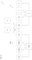
- the Figure 2 shows a schematic side view of a carriage 100. It can be seen how the carriage 100 is arranged on the support cable 2 so that it can move via the rollers 102.
- the traction cable 3 is connected to the carriage 100 at an attachment point 3c and is moved in the traction direction Z to move the carriage toward the deflection pulley 3a. After being deflected over the deflection pulley 3a, the traction cable 3 is guided by the guide pulley 3d into the carriage 100. The traction cable 3 then wraps around the parabolic disk 106 in the carriage 100.
- the parabolic disc 106 is therefore rotated with each movement of the traction cable 3. Via a belt drive 107a, the rotational movement of the parabolic disc 106 is transmitted to a generator 107, which converts the rotational movement into electrical energy The traction cable 3 is then guided out of the carriage 100 via another guide roller 3d.
- a hoist winch 103 with a hoist cable 103a is also visible.
- the hoist cable 103a can be wound up or unwound on a drum 103c of the hoist winch 103.
- the drum 103c is driven by a further electric motor 104a of the drive unit 104 via a belt drive 104b and a gear with a brake 104c.
- a hoist cable guide roller 103d serves to guide the hoist cable 103a.
- a lifting means 103b is only indicated.
- the additional electric motor 104a can be operated as a generator and thus convert the rotational movement of the drum 103c into electrical energy via the belt drive 104b when unwinding.
- the generator 107, the further electric motor 104a, the energy storage device 105, the further control unit 108 and the radio module 110 are connected to one another by electrical lines not shown.
- the energy storage device 105 can be charged via the additional control unit 108 with the energy generated by the generator 107 and/or the additional electric motor 104a operating as a generator.
- the additional control unit 108 monitors and regulates or controls the charging process so that the energy storage device 105 is always charged properly and efficiently.
- the additional electric motor 104a can also be controlled via the control unit 108.
- Corresponding control commands can be received, for example, by the radio module 110 and processed and forwarded by the control unit 108.
- This additional control unit 108 can reduce the load on the control unit 9, since only control and/or regulation processes relating to the carriage 100 can be carried out directly on the carriage 100.
- the additional control unit 108 can also receive commands from the control unit 9, for example via the radio module 110, and further process and forward them.
- data such as sensor data from the generator 7, the further electric motor 4a or the further battery management system 105a can also be sent via the radio module 110 to the remote control 8 and/or the control unit 9 for further processing.
- the Figure 3a shows a schematic front view of a carriage 100 according to the invention
- the Figure 3b a schematic rear view of a carriage 100 according to the invention.
- the carriage 100 has a support beam 111, to which the support arms 112 are also attached.
- the support arms 112 are arranged off-center, but the rollers 102 are arranged centrally.
- the rollers 102 rest on the support cable 2.
- any suitable configuration of rollers 102 is conceivable, not just the one shown here.
- the traction cable 3 is guided into the carriage 100 and up onto the parabolic disk 106 via the guide roller 3d.
- the traction cable 3 wraps around the parabolic disk 106 once or twice, whereby the disk is driven by each movement of the traction cable 3. It can be seen that the traction cable 3 is displaced on the parabolic disk 106 by one supporting cable diameter, which makes such wrapping possible.
- the parabolic disk 106 is connected via a gear 106a to the belt drive 107a, which drives the generator 107.
Landscapes
- Engineering & Computer Science (AREA)
- Mechanical Engineering (AREA)
- Automation & Control Theory (AREA)
- Jib Cranes (AREA)
- Electric Cable Arrangement Between Relatively Moving Parts (AREA)
- Control And Safety Of Cranes (AREA)
Claims (14)
- Système de grue à câble (1) avec- au moins un chariot (100),- au moins un câble porteur (2), sur lequel l'au moins un chariot (100) est disposé ou peut être disposé de manière mobile,- au moins un câble de traction (3) réalisé en tant que câble sans fin (3), lequel est disposé sur l'au moins un chariot (100), et- au moins un dispositif de treuil (4) pour le déplacement de l'au moins un chariot (100), au moyen duquel l'au moins un câble de traction (3) peut être enroulé et déroulé,dans lequel l'au moins un dispositif de treuil (4) comprend au moins un moteur électrique (5) pour le fonctionnement de l'au moins un dispositif de treuil (4), et dans lequel l'au moins un moteur électrique (5) peut fonctionner en tant que générateur, dans lequel l'au moins un moteur électrique (5) fonctionnant en tant que générateur peut être entraîné par un mouvement de déplacement de l'au moins un chariot (100),dans lequel l'au moins un chariot (100) comprend au moins deux galets (102), sur lesquels l'au moins un chariot (100) peut être disposé de manière mobile sur un câble porteur (2), au moins un treuil de levage (103) et une unité d'entraînement (104) pour entraîner l'au moins un treuil de levage (103), et un autre accumulateur d'énergie (105) pour alimenter l'unité d'entraînement (104), dans lequel l'autre accumulateur d'énergie (105) peut être rechargé par l'intermédiaire d'un générateur (107, 104a) entraîné par l'au moins un chariot (100).
- Système de grue à câble selon la revendication 1, dans lequel l'au moins un dispositif de treuil à câble (4) comprend au moins un tambour de câble (4a) sur lequel l'au moins un câble de traction (3) peut être enroulé et déroulé.
- Système de grue à câble selon la revendication 2, dans lequel l'au moins un tambour de câble (4a) peut être entraîné par l'au moins un moteur électrique (5) et/ou l'au moins un moteur électrique (5) fonctionnant comme générateur peut être entraîné par le tambour de câble (4a) lors du déroulement ou de l'enroulement du câble de traction (3) du tambour de câble (4a).
- Système de grue à câble selon l'une quelconque des revendications 1 à 3, dans lequel le système de grue à câble (1) comprend au moins un accumulateur d'énergie (6) pour l'alimentation de l'au moins un moteur électrique (5), dans lequel l'au moins un accumulateur d'énergie (6) peut être rechargé par l'intermédiaire de l'au moins un moteur électrique (5) fonctionnant en tant que générateur.
- Système de grue à câble selon l'une quelconque des revendications 1 à 4, dans lequel l'au moins un dispositif de treuil à câble (4) comprend une unité de charge (7), par l'intermédiaire de laquelle au moins un consommateur externe (V) peut être alimenté en une énergie générée par au moins un moteur électrique (5) fonctionnant en tant que générateur et/ou en une énergie stockée dans l'au moins un accumulateur d'énergie (6).
- Système de grue à câble selon l'une quelconque des revendications 1 à 5, dans lequel le générateur (107, 104a) est entraîné par un mouvement de déplacement de l'au moins un chariot (100) et/ou par une opération de déroulement de l'au moins un treuil de levage (103).
- Système de grue à câble selon l'une quelconque des revendications 1 à 6, dans lequel l'unité d'entraînement (104) comprend un moteur électrique (104a), dans lequel le moteur électrique (104a) peut fonctionner de préférence en tant que générateur lors d'une opération de déroulement de l'au moins un treuil de levage (103).
- Système de grue à câble selon l'une quelconque des revendications 1 à 7, dans lequel l'au moins un dispositif de treuil à câble (4), l'au moins un chariot (100) et/ou l'au moins un consommateur externe (V) sont en liaison de données (D) entre eux, de préférence sans fil.
- Système de grue à câble selon l'une quelconque des revendications 1 à 8, dans lequel l'au moins un chariot (100) et/ou l'au moins un dispositif de treuil à câble (4) peuvent être commandés à distance par l'intermédiaire d'une télécommande (8), de préférence d'une télécommande radio.
- Système de grue à câble selon l'une quelconque des revendications 1 à 9, dans lequel l'installation de grue à câble (1) comprend au moins une unité de commande (9) pour commander et/ou réguler- l'au moins un moteur électrique (5),- l'au moins un accumulateur d'énergie (6),- l'unité de chargement (7),- l'unité d'entraînement (104),- le générateur (107, 104a),- l'autre accumulateur d'énergie (105),- une télécommande (8), et/ou- une liaison de données (D).
- Système de grue à câble selon la revendication 10, dans lequel l'au moins une unité de commande (9) est disposée sur ou dans l'au moins un dispositif de treuil (4) et/ou sur ou dans l'au moins un chariot (100) ou séparément de l'au moins un dispositif de treuil (4) et de l'au moins un chariot (100).
- Système de grue à câble selon l'une quelconque des revendications 10 ou 11, dans lequel au moins un des chariots (100) présente une autre unité de commande (108) pour commander et/ou réguler le chariot (100), de préférence l'unité d'entraînement (104), le générateur (107, 104a) et/ou l'autre accumulateur d'énergie (105).
- Système de grue à câble selon l'une quelconque des revendications 10 à 12, dans lequel l'unité de commande (9) permet de recharger l'au moins un accumulateur d'énergie (6) en fonction d'un état de charge de l'autre accumulateur d'énergie (105) et/ou l'autre accumulateur d'énergie (105) en fonction d'un état de charge de l'au moins un accumulateur d'énergie (6).
- Système de grue à câble selon l'une quelconque des revendications 1 à 13, caractérisé en ce que le système de grue à câble (1) présente, dans un état de transport, des dimensions maximales de 5,8 m x 2,3 m x 2,3 m (L x l x H).
Applications Claiming Priority (1)
| Application Number | Priority Date | Filing Date | Title |
|---|---|---|---|
| ATA50365/2021A AT524983B1 (de) | 2021-05-12 | 2021-05-12 | Laufwagen für einen Seilkran |
Publications (3)
| Publication Number | Publication Date |
|---|---|
| EP4089043A1 EP4089043A1 (fr) | 2022-11-16 |
| EP4089043B1 true EP4089043B1 (fr) | 2025-07-02 |
| EP4089043C0 EP4089043C0 (fr) | 2025-07-02 |
Family
ID=81648301
Family Applications (1)
| Application Number | Title | Priority Date | Filing Date |
|---|---|---|---|
| EP22173012.0A Active EP4089043B1 (fr) | 2021-05-12 | 2022-05-12 | Système de câble grue |
Country Status (2)
| Country | Link |
|---|---|
| EP (1) | EP4089043B1 (fr) |
| AT (1) | AT524983B1 (fr) |
Families Citing this family (1)
| Publication number | Priority date | Publication date | Assignee | Title |
|---|---|---|---|---|
| AT527941B1 (de) * | 2024-08-22 | 2025-08-15 | Gebrueder Ladstaetter Kg | Laufwagen für eine Seilkrananlage |
Family Cites Families (4)
| Publication number | Priority date | Publication date | Assignee | Title |
|---|---|---|---|---|
| US4687109A (en) * | 1986-07-03 | 1987-08-18 | Davis Glenn T | Radio controlled electric slack puller, brake and battery recharging system |
| AT512872B1 (de) * | 2012-05-11 | 2015-02-15 | Koller Gmbh | Elektrische Seilausspulung eines Seilkrans |
| IT201600099746A1 (it) * | 2016-10-05 | 2018-04-05 | Stefan Leitner | Carrello automotore per gru a fune con recupero di energia |
| AT521032B1 (de) * | 2018-06-19 | 2019-10-15 | Mm Forsttechnik Gmbh | Universallaufwagen mit Zwangsausspulung des Zugseils beziehungsweise des Hubseiles im 2- und 3-Seilbetrieb |
-
2021
- 2021-05-12 AT ATA50365/2021A patent/AT524983B1/de active
-
2022
- 2022-05-12 EP EP22173012.0A patent/EP4089043B1/fr active Active
Also Published As
| Publication number | Publication date |
|---|---|
| EP4089043C0 (fr) | 2025-07-02 |
| EP4089043A1 (fr) | 2022-11-16 |
| AT524983B1 (de) | 2023-04-15 |
| AT524983A1 (de) | 2022-11-15 |
Similar Documents
| Publication | Publication Date | Title |
|---|---|---|
| EP3810541B1 (fr) | Chariot universel comprenant un déroulement par contrainte du câble de traction ou du câble de levage dans un fonctionnement à 2 et à 3 câbles | |
| DE102010063911A1 (de) | Kran | |
| AT15760U1 (de) | Kran und Verfahren zum Betrieb eines Krans mit Energierückgewinnung aus Kranoperationen als sekundäres Energiequellenfeld | |
| DE102016116322B4 (de) | Bremsvorrichtung für eine elektrische Winde | |
| EP3297946B1 (fr) | Treuil de puits mobile | |
| EP3600940B1 (fr) | Véhicule souterrain à entraînement électrique, en particulier engin de pelletage | |
| EP4089043B1 (fr) | Système de câble grue | |
| EP3529192A1 (fr) | Pont roulant | |
| DE212011100176U1 (de) | Energierückgewinnende Seilanlage mit Brennstoffzellen | |
| EP2794458A1 (fr) | Treuil forestier | |
| WO2014040716A1 (fr) | Éolienne volante multicâbles à fonctionnement en yoyo | |
| DE102010013670A1 (de) | Doppel-Hybridspeichersystem | |
| EP3523236B1 (fr) | Chariot autotracté avec récupération d'énergie pour téléphériques | |
| EP3006389B1 (fr) | Transstockeur et procede de fonctionnement d'un transstockeur | |
| AT512872B1 (de) | Elektrische Seilausspulung eines Seilkrans | |
| DE102008013688A1 (de) | Verfahren zum Anheben schwerer Lasten in einem Maschinenhaus einer Windenergieanlage | |
| EP4008676A1 (fr) | Système d'installation à câbles à télécommande, en particulier pour le transport de matériaux tels que le bois | |
| AT523714B1 (de) | Laufwagen mit Greiferbetriebsmodus | |
| DE19831204A1 (de) | Verfahren und Vorrichtung zum Betrieb von elektromotorisch angetriebenen Fahrzeugen | |
| AT527941B1 (de) | Laufwagen für eine Seilkrananlage | |
| DE102016109211B4 (de) | System mit einer Hilfsmaschine zur Positionierung eines Rotors einer Windenergieanlage sowie Verfahren zur Positionierung eines Rotors einer Windenergieanlage | |
| SK288221B6 (sk) | Lanový vozík s autonómnym pohonom a spôsob autonómneho pohonu | |
| CN111717794A (zh) | 自行式小车及起重机 | |
| DE2633529C3 (de) | Antriebssystem für ein elektrisch angetriebenes fahrweggebundenes Verkehrsmittel | |
| DE102022121973B4 (de) | Seilfördersystem, insbesondere für eine Funsportanlage |
Legal Events
| Date | Code | Title | Description |
|---|---|---|---|
| PUAI | Public reference made under article 153(3) epc to a published international application that has entered the european phase |
Free format text: ORIGINAL CODE: 0009012 |
|
| STAA | Information on the status of an ep patent application or granted ep patent |
Free format text: STATUS: THE APPLICATION HAS BEEN PUBLISHED |
|
| AK | Designated contracting states |
Kind code of ref document: A1 Designated state(s): AL AT BE BG CH CY CZ DE DK EE ES FI FR GB GR HR HU IE IS IT LI LT LU LV MC MK MT NL NO PL PT RO RS SE SI SK SM TR |
|
| STAA | Information on the status of an ep patent application or granted ep patent |
Free format text: STATUS: REQUEST FOR EXAMINATION WAS MADE |
|
| 17P | Request for examination filed |
Effective date: 20230512 |
|
| RBV | Designated contracting states (corrected) |
Designated state(s): AL AT BE BG CH CY CZ DE DK EE ES FI FR GB GR HR HU IE IS IT LI LT LU LV MC MK MT NL NO PL PT RO RS SE SI SK SM TR |
|
| STAA | Information on the status of an ep patent application or granted ep patent |
Free format text: STATUS: EXAMINATION IS IN PROGRESS |
|
| 17Q | First examination report despatched |
Effective date: 20240508 |
|
| GRAP | Despatch of communication of intention to grant a patent |
Free format text: ORIGINAL CODE: EPIDOSNIGR1 |
|
| STAA | Information on the status of an ep patent application or granted ep patent |
Free format text: STATUS: GRANT OF PATENT IS INTENDED |
|
| INTG | Intention to grant announced |
Effective date: 20250306 |
|
| GRAS | Grant fee paid |
Free format text: ORIGINAL CODE: EPIDOSNIGR3 |
|
| GRAA | (expected) grant |
Free format text: ORIGINAL CODE: 0009210 |
|
| STAA | Information on the status of an ep patent application or granted ep patent |
Free format text: STATUS: THE PATENT HAS BEEN GRANTED |
|
| AK | Designated contracting states |
Kind code of ref document: B1 Designated state(s): AL AT BE BG CH CY CZ DE DK EE ES FI FR GB GR HR HU IE IS IT LI LT LU LV MC MK MT NL NO PL PT RO RS SE SI SK SM TR |
|
| REG | Reference to a national code |
Ref country code: GB Ref legal event code: FG4D Free format text: NOT ENGLISH |
|
| REG | Reference to a national code |
Ref country code: CH Ref legal event code: EP |
|
| REG | Reference to a national code |
Ref country code: DE Ref legal event code: R096 Ref document number: 502022004466 Country of ref document: DE |
|
| REG | Reference to a national code |
Ref country code: IE Ref legal event code: FG4D Free format text: LANGUAGE OF EP DOCUMENT: GERMAN |
|
| U01 | Request for unitary effect filed |
Effective date: 20250729 |
|
| U07 | Unitary effect registered |
Designated state(s): AT BE BG DE DK EE FI FR IT LT LU LV MT NL PT RO SE SI Effective date: 20250804 |
|
| PG25 | Lapsed in a contracting state [announced via postgrant information from national office to epo] |
Ref country code: IS Free format text: LAPSE BECAUSE OF FAILURE TO SUBMIT A TRANSLATION OF THE DESCRIPTION OR TO PAY THE FEE WITHIN THE PRESCRIBED TIME-LIMIT Effective date: 20251102 |
|
| PG25 | Lapsed in a contracting state [announced via postgrant information from national office to epo] |
Ref country code: NO Free format text: LAPSE BECAUSE OF FAILURE TO SUBMIT A TRANSLATION OF THE DESCRIPTION OR TO PAY THE FEE WITHIN THE PRESCRIBED TIME-LIMIT Effective date: 20251002 |
|
| PG25 | Lapsed in a contracting state [announced via postgrant information from national office to epo] |
Ref country code: HR Free format text: LAPSE BECAUSE OF FAILURE TO SUBMIT A TRANSLATION OF THE DESCRIPTION OR TO PAY THE FEE WITHIN THE PRESCRIBED TIME-LIMIT Effective date: 20250702 |
|
| PG25 | Lapsed in a contracting state [announced via postgrant information from national office to epo] |
Ref country code: GR Free format text: LAPSE BECAUSE OF FAILURE TO SUBMIT A TRANSLATION OF THE DESCRIPTION OR TO PAY THE FEE WITHIN THE PRESCRIBED TIME-LIMIT Effective date: 20251003 |
|
| PG25 | Lapsed in a contracting state [announced via postgrant information from national office to epo] |
Ref country code: CZ Free format text: LAPSE BECAUSE OF FAILURE TO SUBMIT A TRANSLATION OF THE DESCRIPTION OR TO PAY THE FEE WITHIN THE PRESCRIBED TIME-LIMIT Effective date: 20250702 |
|
| PG25 | Lapsed in a contracting state [announced via postgrant information from national office to epo] |
Ref country code: PL Free format text: LAPSE BECAUSE OF FAILURE TO SUBMIT A TRANSLATION OF THE DESCRIPTION OR TO PAY THE FEE WITHIN THE PRESCRIBED TIME-LIMIT Effective date: 20250702 |
|
| PG25 | Lapsed in a contracting state [announced via postgrant information from national office to epo] |
Ref country code: RS Free format text: LAPSE BECAUSE OF FAILURE TO SUBMIT A TRANSLATION OF THE DESCRIPTION OR TO PAY THE FEE WITHIN THE PRESCRIBED TIME-LIMIT Effective date: 20251002 |
|
| PG25 | Lapsed in a contracting state [announced via postgrant information from national office to epo] |
Ref country code: ES Free format text: LAPSE BECAUSE OF FAILURE TO SUBMIT A TRANSLATION OF THE DESCRIPTION OR TO PAY THE FEE WITHIN THE PRESCRIBED TIME-LIMIT Effective date: 20250702 |
|
| PG25 | Lapsed in a contracting state [announced via postgrant information from national office to epo] |
Ref country code: SM Free format text: LAPSE BECAUSE OF FAILURE TO SUBMIT A TRANSLATION OF THE DESCRIPTION OR TO PAY THE FEE WITHIN THE PRESCRIBED TIME-LIMIT Effective date: 20250702 |