EP4089286B1 - Umkehrlüfter - Google Patents
Umkehrlüfter Download PDFInfo
- Publication number
- EP4089286B1 EP4089286B1 EP22169823.6A EP22169823A EP4089286B1 EP 4089286 B1 EP4089286 B1 EP 4089286B1 EP 22169823 A EP22169823 A EP 22169823A EP 4089286 B1 EP4089286 B1 EP 4089286B1
- Authority
- EP
- European Patent Office
- Prior art keywords
- fin
- impeller
- curved surface
- normal
- reverse
- Prior art date
- Legal status (The legal status is an assumption and is not a legal conclusion. Google has not performed a legal analysis and makes no representation as to the accuracy of the status listed.)
- Active
Links
Images





Classifications
-
- F—MECHANICAL ENGINEERING; LIGHTING; HEATING; WEAPONS; BLASTING
- F04—POSITIVE - DISPLACEMENT MACHINES FOR LIQUIDS; PUMPS FOR LIQUIDS OR ELASTIC FLUIDS
- F04D—NON-POSITIVE-DISPLACEMENT PUMPS
- F04D25/00—Pumping installations or systems
- F04D25/02—Units comprising pumps and their driving means
- F04D25/06—Units comprising pumps and their driving means the pump being electrically driven
-
- F—MECHANICAL ENGINEERING; LIGHTING; HEATING; WEAPONS; BLASTING
- F04—POSITIVE - DISPLACEMENT MACHINES FOR LIQUIDS; PUMPS FOR LIQUIDS OR ELASTIC FLUIDS
- F04D—NON-POSITIVE-DISPLACEMENT PUMPS
- F04D29/00—Details, component parts, or accessories
- F04D29/40—Casings; Connections of working fluid
- F04D29/52—Casings; Connections of working fluid for axial pumps
- F04D29/522—Casings; Connections of working fluid for axial pumps especially adapted for elastic fluid pumps
-
- F—MECHANICAL ENGINEERING; LIGHTING; HEATING; WEAPONS; BLASTING
- F04—POSITIVE - DISPLACEMENT MACHINES FOR LIQUIDS; PUMPS FOR LIQUIDS OR ELASTIC FLUIDS
- F04D—NON-POSITIVE-DISPLACEMENT PUMPS
- F04D29/00—Details, component parts, or accessories
- F04D29/40—Casings; Connections of working fluid
- F04D29/52—Casings; Connections of working fluid for axial pumps
- F04D29/522—Casings; Connections of working fluid for axial pumps especially adapted for elastic fluid pumps
- F04D29/526—Details of the casing section radially opposing blade tips
-
- F—MECHANICAL ENGINEERING; LIGHTING; HEATING; WEAPONS; BLASTING
- F04—POSITIVE - DISPLACEMENT MACHINES FOR LIQUIDS; PUMPS FOR LIQUIDS OR ELASTIC FLUIDS
- F04D—NON-POSITIVE-DISPLACEMENT PUMPS
- F04D29/00—Details, component parts, or accessories
- F04D29/60—Mounting; Assembling; Disassembling
- F04D29/64—Mounting; Assembling; Disassembling of axial pumps
- F04D29/644—Mounting; Assembling; Disassembling of axial pumps especially adapted for elastic fluid pumps
- F04D29/646—Mounting or removal of fans
-
- F—MECHANICAL ENGINEERING; LIGHTING; HEATING; WEAPONS; BLASTING
- F04—POSITIVE - DISPLACEMENT MACHINES FOR LIQUIDS; PUMPS FOR LIQUIDS OR ELASTIC FLUIDS
- F04D—NON-POSITIVE-DISPLACEMENT PUMPS
- F04D29/00—Details, component parts, or accessories
- F04D29/66—Combating cavitation, whirls, noise, vibration or the like; Balancing
- F04D29/661—Combating cavitation, whirls, noise, vibration or the like; Balancing especially adapted for elastic fluid pumps
-
- H—ELECTRICITY
- H02—GENERATION; CONVERSION OR DISTRIBUTION OF ELECTRIC POWER
- H02K—DYNAMO-ELECTRIC MACHINES
- H02K7/00—Arrangements for handling mechanical energy structurally associated with dynamo-electric machines, e.g. structural association with mechanical driving motors or auxiliary dynamo-electric machines
- H02K7/14—Structural association with mechanical loads, e.g. with hand-held machine tools or fans
-
- F—MECHANICAL ENGINEERING; LIGHTING; HEATING; WEAPONS; BLASTING
- F04—POSITIVE - DISPLACEMENT MACHINES FOR LIQUIDS; PUMPS FOR LIQUIDS OR ELASTIC FLUIDS
- F04D—NON-POSITIVE-DISPLACEMENT PUMPS
- F04D19/00—Axial-flow pumps
- F04D19/002—Axial flow fans
- F04D19/005—Axial flow fans reversible fans
-
- F—MECHANICAL ENGINEERING; LIGHTING; HEATING; WEAPONS; BLASTING
- F04—POSITIVE - DISPLACEMENT MACHINES FOR LIQUIDS; PUMPS FOR LIQUIDS OR ELASTIC FLUIDS
- F04D—NON-POSITIVE-DISPLACEMENT PUMPS
- F04D25/00—Pumping installations or systems
- F04D25/02—Units comprising pumps and their driving means
- F04D25/08—Units comprising pumps and their driving means the working fluid being air, e.g. for ventilation
-
- F—MECHANICAL ENGINEERING; LIGHTING; HEATING; WEAPONS; BLASTING
- F04—POSITIVE - DISPLACEMENT MACHINES FOR LIQUIDS; PUMPS FOR LIQUIDS OR ELASTIC FLUIDS
- F04D—NON-POSITIVE-DISPLACEMENT PUMPS
- F04D29/00—Details, component parts, or accessories
- F04D29/40—Casings; Connections of working fluid
- F04D29/52—Casings; Connections of working fluid for axial pumps
- F04D29/54—Fluid-guiding means, e.g. diffusers
- F04D29/541—Specially adapted for elastic fluid pumps
-
- F—MECHANICAL ENGINEERING; LIGHTING; HEATING; WEAPONS; BLASTING
- F05—INDEXING SCHEMES RELATING TO ENGINES OR PUMPS IN VARIOUS SUBCLASSES OF CLASSES F01-F04
- F05D—INDEXING SCHEME FOR ASPECTS RELATING TO NON-POSITIVE-DISPLACEMENT MACHINES OR ENGINES, GAS-TURBINES OR JET-PROPULSION PLANTS
- F05D2240/00—Components
- F05D2240/10—Stators
- F05D2240/12—Fluid guiding means, e.g. vanes
- F05D2240/126—Baffles or ribs
-
- F—MECHANICAL ENGINEERING; LIGHTING; HEATING; WEAPONS; BLASTING
- F05—INDEXING SCHEMES RELATING TO ENGINES OR PUMPS IN VARIOUS SUBCLASSES OF CLASSES F01-F04
- F05D—INDEXING SCHEME FOR ASPECTS RELATING TO NON-POSITIVE-DISPLACEMENT MACHINES OR ENGINES, GAS-TURBINES OR JET-PROPULSION PLANTS
- F05D2250/00—Geometry
- F05D2250/70—Shape
- F05D2250/71—Shape curved
Definitions
- the present disclosure relates to a reversible fan.
- a reversible fan that produces a current of air in the normal direction and the reverse direction is known from, for example, Japanese Patent No. 6802022 and DE 26 07 159 A1 .
- a spring force which swings the impeller blades back into the starting position when the impeller is stopped, further comprising a locking device, the movable part of which is designed as a centrifugal weight and retains the impeller blades above a certain impeller speed, wherein the impeller blades, when they are in the starting position, are in the conveying position which is effective for one direction of rotation and thus for one conveying direction and in that the impeller blades can be pivoted from the starting position into the end position, in which the impeller blades are in a conveying position which is effective for the other conveying direction, only when they are reversed in the other direction of fan rotation, and in that, furthermore, the locking device retains the impeller blades either in the starting position or in the end position, depending on the direction of fan rotation.
- the present disclosure provides a reversible fan according to claim 1.
- the reversible fan includes an impeller configured to be rotatable about a rotation axis and having a plurality of blades radially attached to the perimeter of the impeller, wherein with rotation of the blades, the impeller is able to provide a current of air either in a normal direction or in a reverse direction, where a direction where air is discharged when the impeller rotates in a normal rotation direction is the normal direction and where a direction where wind is discharged when the impeller rotates in a reverse rotation direction is the reverse direction; a motor configured to rotate the impeller; a motor configured to rotate the impeller, , said motor being assembled in the impeller in such a manner as to be placed on the normal direction side relative the impeller; a base portion supporting the motor and being provided in such manner a to cover the normal direction side of the motor; and a tubular frame housing the impeller and the motor and the base portion .
- the reversible fan further comprises a fin protruding inward in a radial direction from an inner peripheral surface of the frame; the fin including a first curved surface, a second curved surface, and an edge, the first curved surface forming a surface in the normal rotation direction of the fin and protruding in the normal rotation direction, the second curved surface forming a surface in the reverse rotation direction of the fin and being recessed in the normal rotation direction, and the edge connecting the first and second curved surfaces.
- the fin is formed in the form of a thin plate including the first curved surface as a front, outer side of the fin and the second curved surface as a back, inner side of the fin and providing an opening portion that is open to a normal rotation direction of the impeller and open to the current of air in the normal direction when the impeller rotates in the normal rotation direction, such that a separation space is formed between the second curved surface of the fin and the inner peripheral surface of the frame, the separation space being configured in such a manner that, when the impeller rotates in the reverse rotation direction, a part of the current of air in the reverse direction is separated to flow in the separation space at an end of the edge in the reverse rotation direction.
- the fin has a shape that allows producing louder noise upon producing the current of air in the normal direction than upon producing the current of air in the reverse direction.
- Such a reversible fan is attached to, for example, the wall of a house.
- the reversible fan is used to draw outside air into the room and increase the room temperature when the outside air is warmer, or discharge the air in the room to the outside and decrease the temperature when the room temperature is high.
- the noise generated when the outside air is drawn in is different from the noise generated when the air in the room is discharged, the resident may suspect that the fan is faulty.
- an object of the present disclosure is to provide a reversible fan that can make the noise level at times of blowing air in the normal direction equal to the noise level at times of blowing air in the reverse direction by increasing the noise level at times of blowing air in the normal direction.
- a reversible fan that can make the noise level at times of blowing air in the normal direction equal to the noise level at times of blowing air in the reverse direction by increasing the noise level at times of blowing air in the normal direction.
- Fig. 1 is a perspective view of a reversible fan 1 according to the embodiment.
- the reversible fan 1 includes an impeller 2 that can rotate about a rotation axis X, a motor 3 that rotates the impeller 2, a base portion 4 that supports the motor 3, and a tubular frame 5 where these members are housed.
- the impeller 2, the motor 3, and the base portion 4 are housed in the frame 5 in such a manner as to overlap along a direction of the rotation axis X.
- a direction (an arrow N direction) where air (a current of air) is discharged when the impeller 2 of the reversible fan 1 illustrated in Fig. 1 rotates in an arrow n direction (a normal rotation direction) is referred to as the normal direction of the reversible fan 1.
- a direction (an arrow R direction) where air (a current of air) is discharged when the impeller 2 rotates in an arrow r direction (a reverse rotation direction) is referred to as the reverse direction of the reversible fan 1.
- the reversible fan 1 is a fan that can blow air (produce a current of air) in both of the normal and reverse directions.
- the impeller 2 is formed in a substantially cup shape.
- a plurality of (five in the example illustrated in the drawing) blades 2a is radially attached to the perimeter of the impeller 2.
- the blades 2a are attached to the impeller 2 in such a manner that surfaces of the blades 2a are inclined with respect to an axial direction (the same direction as the rotation axis X) of a rotating shaft portion of the reversible fan 1. With the rotation of the blades 2a, the impeller 2 produces a current of air in the normal or reverse direction.
- the motor 3 is provided in the impeller 2.
- the motor 3 is configured as, for example, an outer rotor brushless motor.
- the motor 3 includes a stator, and a rotor that is placed outward of the stator.
- the rotor portion of the motor 3 in the impeller 2 is fixed to the impeller 2.
- the motor 3 is assembled in the impeller 2 in such a manner as to be placed on the front side (the normal direction side) relative to the impeller 2.
- the base portion 4 is formed in the form of, for example, a circular cup.
- the base portion 4 is provided in such a manner as to cover the front side of the motor 3.
- the base portion 4 supports the stator portion of the motor 3.
- the base portion 4 is assembled in the frame 5 in such a manner as to be placed on the front side relative to the motor 3.
- the base portion 4 is supported by a plurality of spokes 6.
- Each of the spokes 6 extends radially in the radial direction from a peripheral portion of the base portion 4 and is connected to an inner peripheral surface of the frame 5.
- the base portion 4 supported by the spokes 6 is attached at a position close to the front side of the tubular frame 5 extending along the rotation axis X.
- the frame 5 includes a main body portion 51 forming the tubular part, and flange portions 52a and 52b provided respectively on outer regions of opposite ends of the main body portion 51.
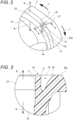
- Fig. 2 is a partial enlarged view illustrating the fin 10 provided in an area A in Fig. 1 .
- Fig. 3 is a cross-sectional view taken along line B-B in Fig. 2 .
- the fin 10 is provided at an end in the reverse direction (the arrow R direction) of the main body portion 51 of the frame 5 in the direction of the rotation axis X.
- the fin 10 extends along the direction of the rotation axis X.
- An inner periphery at the end in the reverse direction of the main body portion 51 on the inner peripheral surface of the frame 5 is provided with a taper surface 53 that expands the diameter in the reverse direction.
- the fin 10 is provided in such a manner as to protrude inward in the radial direction from the taper surface 53 of the main body portion 51.
- the fin 10 is provided in such a manner as to protrude inward in the radial direction from a surface in an area lying across the taper surface 53 of the main body portion 51 and the inner peripheral surface of the main body portion 51 contiguous with the taper surface 53.
- the taper surface 53 of the main body portion 51 is formed in the form of a curved surface protruding inward in the radial direction.
- the fin 10 is formed in such a manner that a width thereof in the peripheral direction is, for example, 3° to 40° with respect to the inner peripheral surface of the frame 5. If the diameter of the reversible fan 1 is, for example, 160 mm, the fin 10 is formed in such a manner that the width is 3° to 7° with respect to the inner peripheral surface of the frame 5. If the diameter is 136 to 126 mm, the fin 10 is formed in such a manner that the width is 4° to 10°. If the diameter is 80 mm, the fin 10 is formed in such a manner that the width is 5° to 15°. If the diameter is 40 mm, the fin 10 is formed in such a manner that the width is 10° to 30°.
- the fin 10 is formed in such a manner as to have a height at which the fin 10 does not come into contact with the blades 2a of the impeller 2 in the direction where the fin 10 protrudes inward in the radial direction. Furthermore, the fin 10 is formed in such a manner as to have a length in the direction of the rotation axis X within a range that does not hinder the path of the impeller 2.
- the fin 10 includes a first curved surface 11 forming a surface in the normal rotation direction (the arrow n direction), a second curved surface 12 forming a surface in the reverse rotation direction (the arrow r direction), and an edge 13 connecting the first curved surface 11 and the second curved surface 12.
- the first curved surface 11 is formed as a curved surface protruding in the normal rotation direction.
- the second curved surface 12 is formed as a curved surface recessed in the normal rotation direction.
- the fin 10 is formed in the form of a thin plate including the first curved surface 11 as the front side and the second curved surface 12 as the back side.
- a separation space 14 where a part of a current of air in a predetermined direction flows is formed between the second curved surface 12 of the fin 10 and the inner peripheral surface of the frame 5 facing the second curved surface 12.
- the separation space 14 is formed between the second curved surface 12 of the fin 10 and the taper surface 53 of the main body portion 51 of the frame 5.
- Fig. 4 illustrates the flow of wind around the fin 10 at times of producing a current of air in the normal direction in the reversible fan 1.
- Fig. 5 illustrates the flow of wind around the fin 10 at times of producing a current of air in the reverse direction in the reversible fan 1.
- a part of a current of air that is produced in the reverse direction when the impeller 2 is rotated in the reverse rotation direction is separated by an end 13p in the reverse rotation direction at the edge 13 of the fin 10, and flows into the separation space 14. Moreover, a part of a current of air that is produced in the normal direction when the impeller 2 is rotated in the normal rotation direction flows into the separation space 14.
- the fin 10 includes an opening portion that is open to the normal rotation direction of the impeller and that is open to the airflow in the normal direction.
- the fin 10 is formed in a shape that has a recess for the airflow in the normal direction.
- the fin 10 is formed in such a manner that the airflow in the reverse direction has smaller fluid resistance than the airflow in the normal direction.
- the fin 10 is configured in such a manner that the airflow hitting the fin 10 produces noise.
- the fin 10 is formed in the shape that allows the airflow in the normal direction to produce louder noise than the airflow in the reverse direction.
- the airflow that has flowed along the first curved surface 11 is separated by the end 13p of the edge 13 of the fin 10 from the first curved surface 11 (an arc portion) of the fin 10 into the separation space 14. Consequently, as indicated by, for example, arrows D1 and D2, the separated airflow creates a vortex (turbulent flow) 15 to some extent in the separation space 14. Hence, the flow becomes regular and stable. Consequently, the noise produced by the airflow in the reverse direction is reduced.
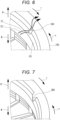
- fins of a first to a third comparative example having shapes where the noise level at times of blowing air in the normal direction is not equal to the noise level at times of blowing air in the reverse direction are described, using Figs. 6 to 8 , to gain a deeper understanding of the fin 10 in the claimed invention.
- Fig. 6 is a perspective view illustrating a fin 100 of the first comparative example (not according to the claimed invention).
- the fin 100 is formed as a straight projection protruding vertically and inward in the radial direction from an inner peripheral surface 151 of a frame 150.
- a surface in the normal rotation direction (the arrow n direction) of the fin 100 configured in this manner is formed as a flat surface.
- Fig. 7 is a perspective view illustrating a fin 200 of the second comparative example (not according to the claimed invention).
- a surface in the normal rotation direction (the arrow n direction) of the fin 200 is formed as a curved surface as in the fin 10 of the above embodiment.
- a surface in the reverse rotation direction (the arrow r direction) of the fin 200 is formed as a flat surface as in the fin 100 of the first comparative example.
- the impeller 2 rotating in the reverse rotation direction produces a current of air in the reverse direction (the arrow R direction)
- the noise level decreases slightly since the surface in the normal rotation direction of the fin 200 is formed as the curved surface.
- the surface in the reverse rotation direction of the fin 200 is formed as the flat surface. Therefore, when the impeller 2 rotating in the normal rotation direction produces a current of air in the normal direction (the arrow N direction), the noise level hardly increases. As a result, it is not possible to reduce the difference between the noise level at times of blowing air in the normal direction and the noise level at times of blowing air in the reverse direction.
- Fig. 8 is a perspective view illustrating a fin 300 of the third comparative example (not according to the claimed invention).
- a surface in the normal rotation direction (the arrow n direction) of the fin 300 is formed as a curved surface as in the fin 10 of the above embodiment.
- a surface in the reverse rotation direction (the arrow r direction) of the fin 300 is formed as a curved surface protruding in the reverse rotation direction.
- the separation space 14 is not provided.
- the fin 10 is provided in the reversible fan 1 according to the embodiment in such a manner as to protrude inward in the radial direction from the inner peripheral surface of the frame 5.
- the fin 10 includes the first curved surface 11, the second curved surface 12, and the edge 13.
- the first curved surface 11 forms the surface in the normal rotation direction of the fin 10, and protrudes in the normal rotation direction.
- the second curved surface 12 forms the surface in the reverse rotation direction of the fin 10 and is recessed in the normal rotation direction.
- the edge 13 connects the first curved surface 11 and the second curved surface 12.
- the separation space 14 is formed between the second curved surface 12 and the inner peripheral surface of the frame 5.
- the separation space 14 separates a part of an airflow at the end 13p in the reverse rotation direction of the edge 13 when the impeller 2 rotates in the reverse rotation direction.
- the airflow in the normal rotation direction (normal direction) produced during positive rotation hits the second curved surface 12.
- the airflow that has hit the second curved surface 12 is disturbed by the second curved surface 12 and produces loud noise.
- the airflow that is produced during the reverse rotation of the impeller 2 and flows in the reverse rotation direction (reverse direction) hits the first curved surface 11.
- the airflow that has hit the first curved surface 11 flows along the first curved surface 11.
- the noise does not increase.
- a part of the airflow produced during the reverse rotation is separated by the separation space 14 and creates a vortex to some extent.
- the airflow during the reverse rotation can be stabilized.
- the noise can be reduced.
- the noise level at times of blowing air in the normal direction can be made equal to the noise level at times of blowing air in the reverse direction.
- the fin 10 has the recess for the airflow in the normal direction n.
- the fin 10 is configured in such a manner that the airflow in the reverse direction has smaller fluid resistance than the airflow in the normal direction.
- the fin 10 produces louder noise due to the airflow in the normal direction than due to the airflow in the reverse direction. Therefore, the noise level at times of blowing air in the normal direction can be made equal to the noise level at times of blowing air in the reverse direction.
- the noise level at times of blowing air in the normal direction can be made equal to the noise level at times of blowing air in the reverse direction without exerting influence on the airflow characteristics, static pressure characteristics, and power consumption of the reversible fan 1.
- the taper surface 53 that expands the diameter in the reverse direction is formed at the end of the frame 5 in the reverse direction in the direction of the rotation axis X.
- the fin 10 is provided on the taper surface 53 of the frame 5 in such a manner as to extend in the direction of the rotation axis X. Such a structure facilitates removal of the frame 5 from a die even if the fin 10 is provided.
- Fig. 9 is a cross-sectional view illustrating a fin 10A of a first modification.
- the fin 10A is different from the fin 10 of the embodiment illustrated in Fig. 3 in the respect of being formed in such a manner that the shape of a separation space 14A in cross section becomes closer to a rectangle as compared with the fin 10.
- the fin 10A is formed in such a manner that a surface 53A on a frame 5A side forming the separation space 14A, that is, the surface 53A facing a second curved surface 12A of the fin 10A extends along the normal direction (the arrow N direction) of the rotation axis X.
- Fig. 10 is a cross-sectional view illustrating a fin 10B of a second modification.
- the fin 10B is formed in such a manner that a surface 53B on a frame 5B side forming a separation space 14B, that is, the surface 53B facing a second curved surface 12B of the fin 10B is configured as a curved surface recessed outward in the radial direction.
- the fin 10B is different from the fin 10 of the embodiment that includes the curved surface protruding inward in the radial direction.
- the shape of the curved surface recessed outward in the radial direction may be provided only to the surface 53B facing the second curved surface 12B. Alternatively, the recessed shape may be provided to the entire taper surface 53 of the main body portion 51 of the frame 5, the taper surface 53 being described in the embodiment.
- Fig. 11 is a cross-sectional view illustrating a fin 10C of a third modification.
- the fin 10C is different from the fin 10B of the second modification illustrated in Fig. 10 in the respect that the direction in which the fin 10C extends is inclined with respect to the direction of the rotation axis X.
- the fin 10C is provided in such a manner as to be inclined inward in the radial direction (in a direction away from a surface 53C on a frame 5C side forming a separation space 14C) in going toward the reverse direction (the arrow R direction).
- the fin 10C is different from the fin 10B of the second modification provided in such a manner as to extend in the direction of the rotation axis X.
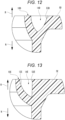
- Fig. 12 is a cross-sectional view illustrating a fin 10D of a fourth modification.
- the fin 10D is formed in such a manner as to be inclined inward in the radial direction (in a direction away from a surface 53D on a frame 5D side forming a separation space 14D) in going toward the reverse direction (the arrow R direction).
- the fin 10D agrees with the fin 10C of the third modification illustrated in Fig. 11 .
- the fin 10D is formed in such a manner as to include a curved surface protruding inward in the radial direction.
- the fin 10C of the third modification without such a curved surface is different from the fin 10D.
- Fig. 13 is a cross-sectional view illustrating a fin 10E of a fifth modification.
- a surface 53E on a frame 5E side forming a separation space 14E that is, the surface 53E facing a second curved surface 12E of the fin 10E is formed along the direction of the rotation axis X.
- the fin 10E is different from the fin 10D of the fourth modification in Fig. 12 that is formed in such a manner as to include the curved surface recessed outward in the radial direction.
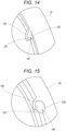
- Fig. 14 is a diagram illustrating a fin 10F of a sixth modification.
- a surface 53F on a frame 5F side forming a separation space 14F that is, the surface 53F facing a second curved surface 12F of the fin 10F is formed along the direction of the rotation axis X.
- the fin 10F is different from the fin 10 of the embodiment in Fig. 2 that is formed in such a manner as to include the curved surface protruding inward in the radial direction.
- Fig. 15 is a diagram illustrating a fin 10G of a seventh modification.
- a surface 53G on a frame 5G side forming a separation space 14G that is, the surface 53G facing a second curved surface 12G of the fin 10G is formed by cutting out a peripheral wall of the frame 5G outward in the radial direction in the form of an arc.
- the fin 10G is different from the fin 10 of the embodiment in Fig. 2 that is formed in such a manner as to include the curved surface protruding inward in the radial direction.
- Fig. 16 is a diagram illustrating a fin 10H of an eighth modification.
- a surface 53H on a frame 5H side forming a separation space 14H that is, the surface 53H facing a second curved surface 12H of the fin 10H is formed by cutting out a peripheral wall of the frame 5H outward in the radial direction in the form of a rectangle.
- the fin 10H is different from the fin 10 of the embodiment in Fig. 2 that is formed in such a manner as to include the curved surface protruding inward in the radial direction.
- the large separation spaces 14A to 14H can be secured.
- the noise level at times of blowing air in the normal direction can be increased. Consequently, the noise level at times of blowing air in the normal direction can be made equal to the noise level at times of blowing air in the reverse direction.
Landscapes
- Engineering & Computer Science (AREA)
- Mechanical Engineering (AREA)
- General Engineering & Computer Science (AREA)
- Power Engineering (AREA)
- Structures Of Non-Positive Displacement Pumps (AREA)
Claims (6)
- Umkehrlüfter (1), das Folgende umfassend:ein Laufrad (2), das so konfiguriert ist, dass es um eine Drehachse (X) drehbar ist und eine Vielzahl von Blättern (2a) aufweist, die radial am Umfang des Laufrads angebracht sind, wobei das Laufrad bei Drehung der Blätter in der Lage ist, einen Luftstrom entweder in einer normalen Richtung (N) oder in einer umgekehrten Richtung (R) bereitzustellen, wobei eine Richtung, in der Luft ausgestoßen wird, wenn sich das Laufrad in einer normalen Drehrichtung (n-Richtung) dreht, die normale Richtung (N) ist und wobei eine Richtung, in der Wind ausgestoßen wird, wenn sich das Laufrad in einer umgekehrten Drehrichtung (r-Richtung) dreht, die umgekehrte Richtung (R) ist;einen Motor (3), der so konfiguriert ist, dass er das Laufrad in Drehung versetzt, wobei der Motor so in das Laufrad eingebaut ist, dass er auf der Seite der normalen Richtung bezüglich des Laufrads angeordnet ist;einen Basisabschnitt (4), der den Motor trägt und so beschaffen ist, dass er die normal ausgerichtete Seite des Motors abdeckt,einen rohrförmigen Rahmen (5), der das Laufrad, den Motor und denBasisabschnitt aufnimmt; gekennzeichnet durch
eine Rippe (10; 10A-H), die in einer radialen Richtung von einer inneren Umfangsfläche (53, 53A-53H) des Rahmens nach innen ragt; wobeidie Rippe eine erste gekrümmte Fläche (11) umfasst, eine zweite gekrümmte Fläche (12; 12A-H) und eine Kante (13),die erste gekrümmte Fläche bildet eine Fläche in der normalen Drehrichtung (n-Richtung) der Rippe und ragt in der normalen Drehrichtung hervor,die zweite gekrümmte Fläche bildet eine Fläche in der umgekehrten Drehrichtung (r-Richtung) der Rippe und ist in der normalen Drehrichtung vertieft,die Kante die erste und die zweite gekrümmte Fläche verbindet, und wobei die Rippe (10) in Form einer dünnen Platte ausgebildet ist, welche die erste gekrümmte Fläche (11) als eine vordere, äußere Seite der Rippe und die zweite gekrümmte Fläche (12) als eine hintere, innere Seite der Rippe enthält und einen Öffnungsabschnitt bereitstellt, der zu einer normalen Drehrichtung (n-Richtung) des Laufrads offen ist und zu dem Luftstrom in der normalen Richtung (N) offen ist, wenn sich das Laufrad in der normalen Drehrichtung dreht, so dass ein Trennraum (14; 14A-H) zwischen der zweiten gekrümmten Fläche der Rippe und der inneren Umfangsfläche (53, 53A-53H) des Rahmens gebildet wird, wobei der Trennraum so konfiguriert ist, dass, wenn sich das Laufrad in der umgekehrten Drehrichtung dreht, ein Teil des Luftstroms in der umgekehrten Richtung getrennt wird, um in dem Trennraum an einem Ende (13p) der Kante (13) in der umgekehrten Drehrichtung zu strömen. - Umkehrlüfter nach Anspruch 1, wobei die Rippe (10; 10A-H) an einem Ende auf der Seite des Rahmens in umgekehrter Richtung in Richtung der Drehachse (X) vorgesehen ist.
- Umkehrlüfter nach Anspruch 1, wobeiein innerer Umfang an einem Ende in der umgekehrten Richtung des Rahmens (5) auf der inneren Umfangsfläche des Rahmens mit einer konischen Fläche (53, 53B-D) versehen ist, die sich im Durchmesser in der umgekehrten Richtung (R) erweitert, unddie Rippe (10, 10B-D) sich in Richtung der Drehachse erstreckt.
- Umkehrlüfter nach Anspruch 3, wobei die Rippe (10, 10B-D) in radialer Richtung von der konischen Fläche (53, 53B-D) nach innen ragt.
- Umkehrlüfter nach Anspruch 3 oder 4, wobei der Trennraum (14; 14A-D) zwischen der zweiten gekrümmten Fläche (12; 12A-D) der Rippe (10; 10A-D) und der konischen Fläche (53, 53B-D) gebildet wird.
- Umkehrlüfter nach Anspruch 1, wobei ein Teil (53, 53B-D, 53G, 53H) der inneren Umfangsfläche des Rahmens (4), welcher der zweiten gekrümmten Fläche (12) der Rippe (10, 10B-D, 10G, 10H) zugewandt ist, in radialer Richtung nach außen vertieft ist.
Applications Claiming Priority (1)
| Application Number | Priority Date | Filing Date | Title |
|---|---|---|---|
| JP2021081097A JP7633878B2 (ja) | 2021-05-12 | 2021-05-12 | リバーシブルファン |
Publications (2)
| Publication Number | Publication Date |
|---|---|
| EP4089286A1 EP4089286A1 (de) | 2022-11-16 |
| EP4089286B1 true EP4089286B1 (de) | 2024-08-28 |
Family
ID=81386834
Family Applications (1)
| Application Number | Title | Priority Date | Filing Date |
|---|---|---|---|
| EP22169823.6A Active EP4089286B1 (de) | 2021-05-12 | 2022-04-25 | Umkehrlüfter |
Country Status (5)
| Country | Link |
|---|---|
| US (1) | US12055150B2 (de) |
| EP (1) | EP4089286B1 (de) |
| JP (1) | JP7633878B2 (de) |
| CN (1) | CN115342067A (de) |
| PH (1) | PH12022050191A1 (de) |
Citations (1)
| Publication number | Priority date | Publication date | Assignee | Title |
|---|---|---|---|---|
| US20180087440A1 (en) * | 2016-09-29 | 2018-03-29 | Sanyo Denki Co., Ltd. | Blast fan |
Family Cites Families (13)
| Publication number | Priority date | Publication date | Assignee | Title |
|---|---|---|---|---|
| DE2607159C3 (de) * | 1976-02-21 | 1979-05-03 | Voith Getriebe Kg, 7920 Heidenheim | Axialventilator |
| JPS6356024A (ja) | 1986-08-27 | 1988-03-10 | Nec Corp | 同期バ−スト送信位相制御方式 |
| CA1333196C (en) * | 1987-12-28 | 1994-11-22 | Yasuyuki Aihara | Engine compartment cooling control system |
| TW562087U (en) * | 2000-06-16 | 2003-11-11 | Delta Electronics Inc | Frame structure for fan |
| KR101155809B1 (ko) * | 2005-03-26 | 2012-06-12 | 한라공조주식회사 | 팬 및 쉬라우드 조립체 |
| US8221074B2 (en) * | 2007-12-21 | 2012-07-17 | Paccar Inc | Fan ring shroud assembly |
| JP5129667B2 (ja) * | 2008-06-26 | 2013-01-30 | 山洋電気株式会社 | 軸流送風機 |
| TW201235568A (en) * | 2011-02-21 | 2012-09-01 | Sunonwealth Electr Mach Ind Co | Cooling fan with dual rotation function |
| TW201518607A (zh) * | 2013-11-14 | 2015-05-16 | Hon Hai Prec Ind Co Ltd | 風扇 |
| US9909485B2 (en) * | 2015-04-17 | 2018-03-06 | Brose Fahrzeugteile GmbH & Co. Kommanditgesellschaft, Würzburg | Cooling fan module and system |
| JP5832052B1 (ja) * | 2015-04-24 | 2015-12-16 | 山洋電気株式会社 | 双方向軸流ファン装置 |
| US10844770B2 (en) * | 2018-12-04 | 2020-11-24 | Brose Fahrzeugteile GmbH & Co. Kommanditgesellschaft, Würzburg | Cooling fan module |
| JP7634421B2 (ja) * | 2021-05-12 | 2025-02-21 | 山洋電気株式会社 | リバーシブルファン |
-
2021
- 2021-05-12 JP JP2021081097A patent/JP7633878B2/ja active Active
-
2022
- 2022-04-25 EP EP22169823.6A patent/EP4089286B1/de active Active
- 2022-04-27 CN CN202210452527.2A patent/CN115342067A/zh active Pending
- 2022-04-28 US US17/731,966 patent/US12055150B2/en active Active
- 2022-05-06 PH PH1/2022/050191A patent/PH12022050191A1/en unknown
Patent Citations (1)
| Publication number | Priority date | Publication date | Assignee | Title |
|---|---|---|---|---|
| US20180087440A1 (en) * | 2016-09-29 | 2018-03-29 | Sanyo Denki Co., Ltd. | Blast fan |
Also Published As
| Publication number | Publication date |
|---|---|
| CN115342067A (zh) | 2022-11-15 |
| TW202247570A (zh) | 2022-12-01 |
| PH12022050191A1 (en) | 2024-02-12 |
| US12055150B2 (en) | 2024-08-06 |
| JP7633878B2 (ja) | 2025-02-20 |
| EP4089286A1 (de) | 2022-11-16 |
| US20220364570A1 (en) | 2022-11-17 |
| JP2022175001A (ja) | 2022-11-25 |
Similar Documents
| Publication | Publication Date | Title |
|---|---|---|
| JP5230805B2 (ja) | 多翼送風機 | |
| JP4442029B2 (ja) | 送風装置 | |
| EP0490308B1 (de) | Mundstückummantelung für Axiallüfter | |
| KR20000023522A (ko) | 축류 송풍기 | |
| CN107923410A (zh) | 螺旋桨式风扇、螺旋桨式风扇装置及空气调节装置用室外机 | |
| TWI699484B (zh) | 雙向軸流風扇裝置 | |
| JP2013130076A (ja) | 軸流ファンに用いられるインペラ、およびそれを用いた軸流ファン | |
| JP2011122570A (ja) | 二重反転式軸流送風機 | |
| JP2010090835A (ja) | 多翼遠心ファンおよびそれを用いた空気調和機 | |
| JP2014173580A (ja) | 送風装置 | |
| JPH102299A (ja) | 遠心送風機 | |
| JP5357492B2 (ja) | プロペラファン | |
| JP4508974B2 (ja) | プロペラファン | |
| EP4089285B1 (de) | Umkehrlüfter | |
| EP4089286A1 (de) | Umkehrlüfter | |
| JP2012197740A (ja) | 軸流送風機 | |
| US12203487B2 (en) | Axial fan | |
| JP7826135B2 (ja) | 軸流ファン | |
| JP7638814B2 (ja) | 軸流ファン | |
| JPS6361800A (ja) | 軸流送風機 | |
| JPH07243397A (ja) | 送風機 | |
| JP2006125229A (ja) | シロッコファン | |
| JP3902193B2 (ja) | 多翼遠心送風機 | |
| JP5008386B2 (ja) | 遠心式多翼送風機 | |
| JP2009030520A (ja) | 送風ファンおよび送風機 |
Legal Events
| Date | Code | Title | Description |
|---|---|---|---|
| PUAI | Public reference made under article 153(3) epc to a published international application that has entered the european phase |
Free format text: ORIGINAL CODE: 0009012 |
|
| STAA | Information on the status of an ep patent application or granted ep patent |
Free format text: STATUS: THE APPLICATION HAS BEEN PUBLISHED |
|
| AK | Designated contracting states |
Kind code of ref document: A1 Designated state(s): AL AT BE BG CH CY CZ DE DK EE ES FI FR GB GR HR HU IE IS IT LI LT LU LV MC MK MT NL NO PL PT RO RS SE SI SK SM TR |
|
| STAA | Information on the status of an ep patent application or granted ep patent |
Free format text: STATUS: REQUEST FOR EXAMINATION WAS MADE |
|
| 17P | Request for examination filed |
Effective date: 20230207 |
|
| RBV | Designated contracting states (corrected) |
Designated state(s): AL AT BE BG CH CY CZ DE DK EE ES FI FR GB GR HR HU IE IS IT LI LT LU LV MC MK MT NL NO PL PT RO RS SE SI SK SM TR |
|
| GRAP | Despatch of communication of intention to grant a patent |
Free format text: ORIGINAL CODE: EPIDOSNIGR1 |
|
| STAA | Information on the status of an ep patent application or granted ep patent |
Free format text: STATUS: GRANT OF PATENT IS INTENDED |
|
| INTG | Intention to grant announced |
Effective date: 20240521 |
|
| GRAS | Grant fee paid |
Free format text: ORIGINAL CODE: EPIDOSNIGR3 |
|
| GRAA | (expected) grant |
Free format text: ORIGINAL CODE: 0009210 |
|
| STAA | Information on the status of an ep patent application or granted ep patent |
Free format text: STATUS: THE PATENT HAS BEEN GRANTED |
|
| AK | Designated contracting states |
Kind code of ref document: B1 Designated state(s): AL AT BE BG CH CY CZ DE DK EE ES FI FR GB GR HR HU IE IS IT LI LT LU LV MC MK MT NL NO PL PT RO RS SE SI SK SM TR |
|
| REG | Reference to a national code |
Ref country code: CH Ref legal event code: EP |
|
| REG | Reference to a national code |
Ref country code: DE Ref legal event code: R096 Ref document number: 602022005593 Country of ref document: DE |
|
| REG | Reference to a national code |
Ref country code: IE Ref legal event code: FG4D |
|
| REG | Reference to a national code |
Ref country code: LT Ref legal event code: MG9D |
|
| PG25 | Lapsed in a contracting state [announced via postgrant information from national office to epo] |
Ref country code: NO Free format text: LAPSE BECAUSE OF FAILURE TO SUBMIT A TRANSLATION OF THE DESCRIPTION OR TO PAY THE FEE WITHIN THE PRESCRIBED TIME-LIMIT Effective date: 20241128 |
|
| REG | Reference to a national code |
Ref country code: AT Ref legal event code: MK05 Ref document number: 1718217 Country of ref document: AT Kind code of ref document: T Effective date: 20240828 |
|
| PG25 | Lapsed in a contracting state [announced via postgrant information from national office to epo] |
Ref country code: FI Free format text: LAPSE BECAUSE OF FAILURE TO SUBMIT A TRANSLATION OF THE DESCRIPTION OR TO PAY THE FEE WITHIN THE PRESCRIBED TIME-LIMIT Effective date: 20240828 Ref country code: PT Free format text: LAPSE BECAUSE OF FAILURE TO SUBMIT A TRANSLATION OF THE DESCRIPTION OR TO PAY THE FEE WITHIN THE PRESCRIBED TIME-LIMIT Effective date: 20241230 Ref country code: NL Free format text: LAPSE BECAUSE OF FAILURE TO SUBMIT A TRANSLATION OF THE DESCRIPTION OR TO PAY THE FEE WITHIN THE PRESCRIBED TIME-LIMIT Effective date: 20240828 Ref country code: PL Free format text: LAPSE BECAUSE OF FAILURE TO SUBMIT A TRANSLATION OF THE DESCRIPTION OR TO PAY THE FEE WITHIN THE PRESCRIBED TIME-LIMIT Effective date: 20240828 Ref country code: GR Free format text: LAPSE BECAUSE OF FAILURE TO SUBMIT A TRANSLATION OF THE DESCRIPTION OR TO PAY THE FEE WITHIN THE PRESCRIBED TIME-LIMIT Effective date: 20241129 |
|
| PG25 | Lapsed in a contracting state [announced via postgrant information from national office to epo] |
Ref country code: BG Free format text: LAPSE BECAUSE OF FAILURE TO SUBMIT A TRANSLATION OF THE DESCRIPTION OR TO PAY THE FEE WITHIN THE PRESCRIBED TIME-LIMIT Effective date: 20240828 |
|
| PG25 | Lapsed in a contracting state [announced via postgrant information from national office to epo] |
Ref country code: LV Free format text: LAPSE BECAUSE OF FAILURE TO SUBMIT A TRANSLATION OF THE DESCRIPTION OR TO PAY THE FEE WITHIN THE PRESCRIBED TIME-LIMIT Effective date: 20240828 |
|
| REG | Reference to a national code |
Ref country code: NL Ref legal event code: MP Effective date: 20240828 |
|
| PG25 | Lapsed in a contracting state [announced via postgrant information from national office to epo] |
Ref country code: AT Free format text: LAPSE BECAUSE OF FAILURE TO SUBMIT A TRANSLATION OF THE DESCRIPTION OR TO PAY THE FEE WITHIN THE PRESCRIBED TIME-LIMIT Effective date: 20240828 Ref country code: IS Free format text: LAPSE BECAUSE OF FAILURE TO SUBMIT A TRANSLATION OF THE DESCRIPTION OR TO PAY THE FEE WITHIN THE PRESCRIBED TIME-LIMIT Effective date: 20241228 |
|
| PG25 | Lapsed in a contracting state [announced via postgrant information from national office to epo] |
Ref country code: HR Free format text: LAPSE BECAUSE OF FAILURE TO SUBMIT A TRANSLATION OF THE DESCRIPTION OR TO PAY THE FEE WITHIN THE PRESCRIBED TIME-LIMIT Effective date: 20240828 |
|
| PG25 | Lapsed in a contracting state [announced via postgrant information from national office to epo] |
Ref country code: ES Free format text: LAPSE BECAUSE OF FAILURE TO SUBMIT A TRANSLATION OF THE DESCRIPTION OR TO PAY THE FEE WITHIN THE PRESCRIBED TIME-LIMIT Effective date: 20240828 Ref country code: RS Free format text: LAPSE BECAUSE OF FAILURE TO SUBMIT A TRANSLATION OF THE DESCRIPTION OR TO PAY THE FEE WITHIN THE PRESCRIBED TIME-LIMIT Effective date: 20241128 |
|
| PG25 | Lapsed in a contracting state [announced via postgrant information from national office to epo] |
Ref country code: RS Free format text: LAPSE BECAUSE OF FAILURE TO SUBMIT A TRANSLATION OF THE DESCRIPTION OR TO PAY THE FEE WITHIN THE PRESCRIBED TIME-LIMIT Effective date: 20241128 Ref country code: PT Free format text: LAPSE BECAUSE OF FAILURE TO SUBMIT A TRANSLATION OF THE DESCRIPTION OR TO PAY THE FEE WITHIN THE PRESCRIBED TIME-LIMIT Effective date: 20241230 Ref country code: PL Free format text: LAPSE BECAUSE OF FAILURE TO SUBMIT A TRANSLATION OF THE DESCRIPTION OR TO PAY THE FEE WITHIN THE PRESCRIBED TIME-LIMIT Effective date: 20240828 Ref country code: NO Free format text: LAPSE BECAUSE OF FAILURE TO SUBMIT A TRANSLATION OF THE DESCRIPTION OR TO PAY THE FEE WITHIN THE PRESCRIBED TIME-LIMIT Effective date: 20241128 Ref country code: NL Free format text: LAPSE BECAUSE OF FAILURE TO SUBMIT A TRANSLATION OF THE DESCRIPTION OR TO PAY THE FEE WITHIN THE PRESCRIBED TIME-LIMIT Effective date: 20240828 Ref country code: LV Free format text: LAPSE BECAUSE OF FAILURE TO SUBMIT A TRANSLATION OF THE DESCRIPTION OR TO PAY THE FEE WITHIN THE PRESCRIBED TIME-LIMIT Effective date: 20240828 Ref country code: IS Free format text: LAPSE BECAUSE OF FAILURE TO SUBMIT A TRANSLATION OF THE DESCRIPTION OR TO PAY THE FEE WITHIN THE PRESCRIBED TIME-LIMIT Effective date: 20241228 Ref country code: HR Free format text: LAPSE BECAUSE OF FAILURE TO SUBMIT A TRANSLATION OF THE DESCRIPTION OR TO PAY THE FEE WITHIN THE PRESCRIBED TIME-LIMIT Effective date: 20240828 Ref country code: GR Free format text: LAPSE BECAUSE OF FAILURE TO SUBMIT A TRANSLATION OF THE DESCRIPTION OR TO PAY THE FEE WITHIN THE PRESCRIBED TIME-LIMIT Effective date: 20241129 Ref country code: FI Free format text: LAPSE BECAUSE OF FAILURE TO SUBMIT A TRANSLATION OF THE DESCRIPTION OR TO PAY THE FEE WITHIN THE PRESCRIBED TIME-LIMIT Effective date: 20240828 Ref country code: ES Free format text: LAPSE BECAUSE OF FAILURE TO SUBMIT A TRANSLATION OF THE DESCRIPTION OR TO PAY THE FEE WITHIN THE PRESCRIBED TIME-LIMIT Effective date: 20240828 Ref country code: BG Free format text: LAPSE BECAUSE OF FAILURE TO SUBMIT A TRANSLATION OF THE DESCRIPTION OR TO PAY THE FEE WITHIN THE PRESCRIBED TIME-LIMIT Effective date: 20240828 Ref country code: AT Free format text: LAPSE BECAUSE OF FAILURE TO SUBMIT A TRANSLATION OF THE DESCRIPTION OR TO PAY THE FEE WITHIN THE PRESCRIBED TIME-LIMIT Effective date: 20240828 |
|
| PG25 | Lapsed in a contracting state [announced via postgrant information from national office to epo] |
Ref country code: SM Free format text: LAPSE BECAUSE OF FAILURE TO SUBMIT A TRANSLATION OF THE DESCRIPTION OR TO PAY THE FEE WITHIN THE PRESCRIBED TIME-LIMIT Effective date: 20240828 Ref country code: DK Free format text: LAPSE BECAUSE OF FAILURE TO SUBMIT A TRANSLATION OF THE DESCRIPTION OR TO PAY THE FEE WITHIN THE PRESCRIBED TIME-LIMIT Effective date: 20240828 Ref country code: RO Free format text: LAPSE BECAUSE OF FAILURE TO SUBMIT A TRANSLATION OF THE DESCRIPTION OR TO PAY THE FEE WITHIN THE PRESCRIBED TIME-LIMIT Effective date: 20240828 |
|
| PG25 | Lapsed in a contracting state [announced via postgrant information from national office to epo] |
Ref country code: EE Free format text: LAPSE BECAUSE OF FAILURE TO SUBMIT A TRANSLATION OF THE DESCRIPTION OR TO PAY THE FEE WITHIN THE PRESCRIBED TIME-LIMIT Effective date: 20240828 |
|
| PG25 | Lapsed in a contracting state [announced via postgrant information from national office to epo] |
Ref country code: CZ Free format text: LAPSE BECAUSE OF FAILURE TO SUBMIT A TRANSLATION OF THE DESCRIPTION OR TO PAY THE FEE WITHIN THE PRESCRIBED TIME-LIMIT Effective date: 20240828 |
|
| PG25 | Lapsed in a contracting state [announced via postgrant information from national office to epo] |
Ref country code: IT Free format text: LAPSE BECAUSE OF FAILURE TO SUBMIT A TRANSLATION OF THE DESCRIPTION OR TO PAY THE FEE WITHIN THE PRESCRIBED TIME-LIMIT Effective date: 20240828 Ref country code: SK Free format text: LAPSE BECAUSE OF FAILURE TO SUBMIT A TRANSLATION OF THE DESCRIPTION OR TO PAY THE FEE WITHIN THE PRESCRIBED TIME-LIMIT Effective date: 20240828 |
|
| REG | Reference to a national code |
Ref country code: DE Ref legal event code: R097 Ref document number: 602022005593 Country of ref document: DE |
|
| PLBE | No opposition filed within time limit |
Free format text: ORIGINAL CODE: 0009261 |
|
| STAA | Information on the status of an ep patent application or granted ep patent |
Free format text: STATUS: NO OPPOSITION FILED WITHIN TIME LIMIT |
|
| 26N | No opposition filed |
Effective date: 20250530 |
|
| PG25 | Lapsed in a contracting state [announced via postgrant information from national office to epo] |
Ref country code: SE Free format text: LAPSE BECAUSE OF FAILURE TO SUBMIT A TRANSLATION OF THE DESCRIPTION OR TO PAY THE FEE WITHIN THE PRESCRIBED TIME-LIMIT Effective date: 20240828 |
|
| REG | Reference to a national code |
Ref country code: CH Ref legal event code: H13 Free format text: ST27 STATUS EVENT CODE: U-0-0-H10-H13 (AS PROVIDED BY THE NATIONAL OFFICE) Effective date: 20251125 |
|
| PG25 | Lapsed in a contracting state [announced via postgrant information from national office to epo] |
Ref country code: LU Free format text: LAPSE BECAUSE OF NON-PAYMENT OF DUE FEES Effective date: 20250425 |
|
| PG25 | Lapsed in a contracting state [announced via postgrant information from national office to epo] |
Ref country code: MC Free format text: LAPSE BECAUSE OF FAILURE TO SUBMIT A TRANSLATION OF THE DESCRIPTION OR TO PAY THE FEE WITHIN THE PRESCRIBED TIME-LIMIT Effective date: 20240828 |
|
| REG | Reference to a national code |
Ref country code: BE Ref legal event code: MM Effective date: 20250430 |
|
| PG25 | Lapsed in a contracting state [announced via postgrant information from national office to epo] |
Ref country code: FR Free format text: LAPSE BECAUSE OF NON-PAYMENT OF DUE FEES Effective date: 20250430 |
|
| PG25 | Lapsed in a contracting state [announced via postgrant information from national office to epo] |
Ref country code: BE Free format text: LAPSE BECAUSE OF NON-PAYMENT OF DUE FEES Effective date: 20250430 |
|
| PG25 | Lapsed in a contracting state [announced via postgrant information from national office to epo] |
Ref country code: CH Free format text: LAPSE BECAUSE OF NON-PAYMENT OF DUE FEES Effective date: 20250430 |
|
| PG25 | Lapsed in a contracting state [announced via postgrant information from national office to epo] |
Ref country code: IE Free format text: LAPSE BECAUSE OF NON-PAYMENT OF DUE FEES Effective date: 20250425 |
|
| PG25 | Lapsed in a contracting state [announced via postgrant information from national office to epo] |
Ref country code: CY Free format text: LAPSE BECAUSE OF FAILURE TO SUBMIT A TRANSLATION OF THE DESCRIPTION OR TO PAY THE FEE WITHIN THE PRESCRIBED TIME-LIMIT Effective date: 20240828 |
|
| PG25 | Lapsed in a contracting state [announced via postgrant information from national office to epo] |
Ref country code: LT Free format text: LAPSE BECAUSE OF FAILURE TO SUBMIT A TRANSLATION OF THE DESCRIPTION OR TO PAY THE FEE WITHIN THE PRESCRIBED TIME-LIMIT Effective date: 20240828 |
|
| PGFP | Annual fee paid to national office [announced via postgrant information from national office to epo] |
Ref country code: DE Payment date: 20260422 Year of fee payment: 5 |