EP4089706B1 - Vakuumschaltröhre - Google Patents
Vakuumschaltröhre Download PDFInfo
- Publication number
- EP4089706B1 EP4089706B1 EP20912455.1A EP20912455A EP4089706B1 EP 4089706 B1 EP4089706 B1 EP 4089706B1 EP 20912455 A EP20912455 A EP 20912455A EP 4089706 B1 EP4089706 B1 EP 4089706B1
- Authority
- EP
- European Patent Office
- Prior art keywords
- movable
- conductor
- grounded tank
- vacuum
- circuit breaker
- Prior art date
- Legal status (The legal status is an assumption and is not a legal conclusion. Google has not performed a legal analysis and makes no representation as to the accuracy of the status listed.)
- Active
Links
Images



Classifications
-
- H—ELECTRICITY
- H01—ELECTRIC ELEMENTS
- H01H—ELECTRIC SWITCHES; RELAYS; SELECTORS; EMERGENCY PROTECTIVE DEVICES
- H01H33/00—High-tension or heavy-current switches with arc-extinguishing or arc-preventing means
- H01H33/60—Switches wherein the means for extinguishing or preventing the arc do not include separate means for obtaining or increasing flow of arc-extinguishing fluid
- H01H33/66—Vacuum switches
- H01H33/662—Housings or protective screens
- H01H33/66207—Specific housing details, e.g. sealing, soldering or brazing
-
- H—ELECTRICITY
- H02—GENERATION; CONVERSION OR DISTRIBUTION OF ELECTRIC POWER
- H02B—BOARDS, SUBSTATIONS OR SWITCHING ARRANGEMENTS FOR THE SUPPLY OR DISTRIBUTION OF ELECTRIC POWER
- H02B13/00—Arrangement of switchgear in which switches are enclosed in, or structurally associated with, a casing, e.g. cubicle
- H02B13/02—Arrangement of switchgear in which switches are enclosed in, or structurally associated with, a casing, e.g. cubicle with metal casing
- H02B13/035—Gas-insulated switchgear
- H02B13/0354—Gas-insulated switchgear comprising a vacuum switch
-
- H—ELECTRICITY
- H01—ELECTRIC ELEMENTS
- H01H—ELECTRIC SWITCHES; RELAYS; SELECTORS; EMERGENCY PROTECTIVE DEVICES
- H01H33/00—High-tension or heavy-current switches with arc-extinguishing or arc-preventing means
- H01H33/60—Switches wherein the means for extinguishing or preventing the arc do not include separate means for obtaining or increasing flow of arc-extinguishing fluid
- H01H33/66—Vacuum switches
- H01H33/662—Housings or protective screens
- H01H33/66238—Specific bellows details
-
- H—ELECTRICITY
- H01—ELECTRIC ELEMENTS
- H01H—ELECTRIC SWITCHES; RELAYS; SELECTORS; EMERGENCY PROTECTIVE DEVICES
- H01H33/00—High-tension or heavy-current switches with arc-extinguishing or arc-preventing means
- H01H33/60—Switches wherein the means for extinguishing or preventing the arc do not include separate means for obtaining or increasing flow of arc-extinguishing fluid
- H01H33/66—Vacuum switches
- H01H33/666—Operating arrangements
- H01H33/6661—Combination with other type of switch, e.g. for load break switches
-
- H—ELECTRICITY
- H01—ELECTRIC ELEMENTS
- H01H—ELECTRIC SWITCHES; RELAYS; SELECTORS; EMERGENCY PROTECTIVE DEVICES
- H01H33/00—High-tension or heavy-current switches with arc-extinguishing or arc-preventing means
- H01H33/60—Switches wherein the means for extinguishing or preventing the arc do not include separate means for obtaining or increasing flow of arc-extinguishing fluid
- H01H33/66—Vacuum switches
- H01H33/662—Housings or protective screens
- H01H33/66207—Specific housing details, e.g. sealing, soldering or brazing
- H01H2033/66223—Details relating to the sealing of vacuum switch housings
Definitions
- the present disclosure relates to a vacuum circuit breaker that includes a grounded tank in which an insulating high-pressure gas is encapsulated and a vacuum valve that is disposed in the grounded tank and configured to interrupt an electric current.
- a circuit breaker that interrupts an electric current in an electric power system generally includes: a stationary contact; a movable contact that can be moved in a direction away from the stationary contact at the time of interruption; a movable conductor connected to the movable contact; and an operation rod that is driven by an operating device to move the movable conductor with the movable contact.
- a vacuum circuit breaker that performs a path opening operation in a vacuum to make current interruption houses a movable contact and a stationary contact in a vacuum chamber that forms a vacuum space.
- the movable contact and the stationary contact are placed within a vacuum container, and a movable conductor extends through the vacuum container out of the vacuum container.
- a bellows is housed in the vacuum container together with the movable contact and stationary contact, the bellows being configured to keep the vacuum chamber airtight.
- the bellows has a shape of tubular bellows, one end of which is fixed to the movable conductor and an opposite end of which is fixed to the vacuum container. The bellows expands and contracts at the times of closing and interruption in association with movement of the movable conductor.
- the vacuum container, the movable conductor, and the bellows are used to constitute a vacuum valve.
- the bellows Since the bellows has a shape of tubular bellows with an expansible construction, the bellows has low strength and may be damaged by a pressure difference between an interior and an exterior of the tube.
- a movable-side frame by which a movable conductor is connected to a movable-side bushing terminal is disposed outside a portion of the vacuum container through which the movable conductor extends.
- a space in the movable-side frame communicates with a space inside a movable-side bushing. For this reason, pressure in the movable-side frame needs to be atmospheric air pressure in order to prevent the bellows from being damaged by the pressure difference between the interior and the exterior thereof.
- Patent Literature 1 discloses a vacuum circuit breaker that sets the inside of a movable-side frame to have atmospheric air pressure by having air vent portions provided in a movable-side support plate and a movable-side bushing terminal, respectively.
- the vacuum circuit breaker disclosed in Patent Literature 1 there is set a filter for each of the air vent portions of the movable-side support plate and the movable-side bushing terminal, thereby restraining ingress of water droplets from the air vent portions.
- Relevant prior art can be found in documents DE19517287A1 , EP3364438A1 , GB2221798A .
- Patent Literature 1 Japanese Patent Application Laid-open No. 2013-58312
- the present disclosure has been made in view of the above circumstances, and an object thereof is to provide a vacuum circuit breaker capable of preventing entrance of water droplets into a grounded tank and preventing damage to a bellows.
- a vacuum circuit breaker comprising: a grounded tank in which an insulating gas is encapsulated, the grounded tank having a tubular shape; a vacuum valve insulatively supported inside the grounded tank, the vacuum valve including a movable contact, a stationary contact, a vacuum container in which the movable contact and the stationary contact are housed, a movable conductor electrically connected to the movable contact, the movable conductor extending out of the vacuum container, and a tubular bellows having one end connected to the movable conductor and an opposite end connected to the vacuum container; a movable-side bushing conductor set in a bushing extending above the grounded tank, the movable-side bushing conductor having a tubular shape; a slider movably disposed inside the movable-side bushing conductor; a movable-side frame that is set adjacent to an outside of the vacuum container in a portion where the movable conductor extend
- the vacuum circuit breaker obtained according to the present disclosure has an advantageous effect that it can prevent entrance of water droplets into the grounded tank and prevent damage to the bellows.
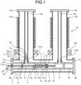
- FIG. 1 is a sectional view of a vacuum circuit breaker according to the first embodiment in a closing state.
- FIG. 2 is a sectional view of the vacuum circuit breaker according to the first embodiment in an interrupting state.
- the vacuum circuit breaker 50 according to the first embodiment includes a tubular grounded tank 1 hermetically containing an insulating gas and a vacuum valve 2 that is insulatively supported inside the grounded tank 1, the valve 2 having a movable contact 2a and a stationary contact 2b.
- the vacuum circuit breaker 50 With an interface between the movable contact 2a and the stationary contact 2b as a boundary, some of members constituting the vacuum circuit breaker 50, serving as a half part thereof including the movable contact 2a are expressed using a wording "movable side", and the remainders of the members, serving as another half part thereof including the stationary contact 2b are expressed using a wording "stationary side".
- the vacuum circuit breaker 50 according to the first embodiment also includes a pair of tubular bushings 13a and 13b extending above the grounded tank 1, a movable-side bushing conductor 12a disposed in the bushing 13a, and a stationary-side bushing conductor 12b disposed in the bushing 13b.
- the vacuum circuit breaker 50 also includes a movable-side bushing terminal 14a that is connected with the movable-side bushing conductor 12a and covers an upper end of the bushing 13a and a stationary-side bushing terminal 14b that is connected with the stationary-side bushing conductor 12b and covers an upper end of the bushing 13b.
- the movable-side and stationary-side bushing terminals 14a and 14b have no vent holes provided therein and an upper end of each of the bushings 13a and 13b is hermetically sealed.
- the bushing 13a is provided with a current transformer 15a that detects an electric current in the movable-side bushing conductor 12a.
- the bushing 13b is provided with a current transformer 15b that detects an electric current in the stationary-side bushing conductor 12b.
- the vacuum valve 2 includes a vacuum container 2c housing the movable and stationary contacts 2a and 2b and a movable conductor 7 having one end 7a electrically connected to the movable contact 2a and an opposite end 7b jutting out from the vacuum container 2c.
- the vacuum valve 2 also includes a stationary conductor 21 electrically connected to the stationary contact 2b and a tubular bellows 3 having one end 3a fixed to the movable conductor 7 and an opposite end 3b fixed to the vacuum container 2c.
- the vacuum circuit breaker 50 also includes: an operating device 30 that is set externally to the grounded tank 1 and configured to insert and pull an operation rod 31 along an axial direction of the grounded tank 1 to switch between a closing state and an interrupting state; the operation rod 31 that has one end 31a connected to the operating device 30 and an opposite end 31b connected to the opposite end 7b of the movable conductor 7; a movable-side frame 5 that electrically connects a lower end 121a of the movable-side bushing conductor 12a to the movable conductor 7; and a stationary-side frame 17 that electrically connects a lower end 121b of the stationary-side bushing conductor 12b to the stationary conductor 21.
- an operating device 30 that is set externally to the grounded tank 1 and configured to insert and pull an operation rod 31 along an axial direction of the grounded tank 1 to switch between a closing state and an interrupting state
- the operation rod 31 that has one end 31a connected to the operating device 30 and an opposite end 31b connected to the opposite end 7b
- the vacuum circuit breaker 50 also includes a movable-side insulating support tube 6 that is configured to insulatively support the movable-side frame 5 with respect to the grounded tank 1 and a stationary-side insulating support tube 18 that is configured to insulatively support the stationary-side frame 17 with respect to the grounded tank 1.
- the vacuum container 2c is fixed to the movable-side frame 5 and the stationary-side frame 17 by bolts, respectively, the bolts being unillustrated.
- the movable-side frame 5 has a hole 34 through which the operation rod 31 passes, and the hole 34 is choked with a packing 35 in an airtight manner.
- the grounded tank 1 has an opening 1a situated on an end portion from which the operation rod 31 sticks out, and the opening 1a is covered with a movable-side support plate 8a having a hole 32 formed therein, the hole 32 being configured to let the operation rod 31 pass therethrough.
- the grounded tank 1 has an opening 1b situated on an end portion on the stationary side, and the opening 1b is covered with a stationary-side support plate 8b.
- a packing 33 is provided in the hole 32 of the movable-side support plate 8a. There is a gap between the movable-side support plate 8a and the operation rod 31, and this gap is closed by a packing 33 in a watertight manner.
- the movable contact 2a receives a driving force from the operating device 30 via the operation rod 31 and the movable conductor 7. Upon the reception, the driving force from the operating device 30 enables the movable contact 2a to contact the stationary contact 2b in a closing state, and otherwise to separate from the stationary contact 2b in an interrupting state.
- the operation rod 31 is provided with a contact pressure spring (not illustrated) by which a force for pressing the movable contact 2a against the stationary contact 2b is applied to the operation rod 31 in a closing state. Therefore, certain electrical conduction performance is ensured between the movable contact 2a and the stationary contact 2b in the closing state.
- the movable-side bushing conductor 12a has a tubular shape, and its lower end 121a is connected to an opening 5a of the movable-side frame 5.
- a movable slider 40 is movably accommodated inside the movable-side bushing conductor 12a.
- the slider 40 includes a movable member 9 and an airtight member 10.
- the movable member 9 has a rigid body.
- the airtight member 10 is made of an elastic material and attached to the movable member 9, and closes a gap between the movable-side bushing conductor 12a and the movable member 9 in an airtight state.
- a ringshaped elastic member having a T-shaped cross-section can be used as the airtight member 10 but is not intended to limit the disclosure.
- a stopper 11 configured to set a lower limit position of a movable range for the slider 40.
- the operating device 30 moves the operation rod 31 in a direction in which the rod 31 is pulled out from the grounded tank 1. Accordingly, the movable conductor 7 fixed to the operation rod 31 moves toward the movable-side support plate 8a. Since the one end 3a of the bellows 3 is fixed to the movable conductor 7, the bellows 3 contracts in association with the movement of the movable conductor 7. By the contraction of the bellows 3, the gas in a portion below a part where the movable member 9 is situated, of the bellows 3, the movable-side frame 5, and the movable-side bushing conductor 12a, is compressed.
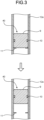
- FIG. 3 illustrates how the slider moves in the interrupting operation of the vacuum circuit breaker according to the first embodiment.
- the slider 40 is movable inside the movable-side bushing conductor 12a, and so the slider 40 cancels out an increase in pressure caused by the contraction of the bellows 3 when moving inside the movable-side bushing conductor 12a.
- the volume of a part below the slider 40 in a space inside the movable-side bushing conductor 12a increases as much as the contraction of the bellows 3 makes a space inside a tube of the bellows 3 smaller. Therefore, a pressure difference between the inside and the outside of a tube of the bellows 3 does not change even in the interrupting operation, and the bellows 3 is prevented from being damaged in the interrupting operation.
- the slider 40 is prevented from intruding into the inside of the movable-side frame 5.
- the movable-side bushing terminal 14a has no hole and the hole 32 in the movable-side support plate 8a penetrated by the operation rod 31 is provided with the packing 33, so that any water droplets can be prevented from entering the grounded tank 1. Moreover, by virtue of the movement of the slider 40 inside the movable-side bushing conductor 12a, the pressure difference is not changed between the inside and the outside of a tube of the bellows 3 even if the bellow 3 expands or contracts, thereby making it possible to prevent the bellows 3 from being damaged in the interrupting operation.
- the slider 40 has the airtight member 10 that is situated at a middle position of the movable member 9 in a longitudinal direction
- the slider 40 may be configured to have two or more airtight members 10 arranged in a vertical direction of the movable member 9.
- the movable member 9 can be prevented from tilting when the slider 40 moves.
- FIG. 4 is a sectional view of a vacuum circuit breaker according to the second embodiment.
- the vacuum circuit breaker 50 according to the second embodiment differs from the vacuum circuit breaker 50 according to the first embodiment in that the slider 40 is configured with a unitary airtight member 16.
- FIG. 5 is an enlarged view of the slider of the vacuum circuit breaker according to the second embodiment.
- the unitary airtight member 16 is made of an elastic material and is in contact with the movable-side bushing conductor 12a in an airtight manner.
- the movable-side bushing terminal 14a has no hole and the hole 32 in the movable-side support plate 8a through which the operation rod 31 penetrates is provided with the packing 33, and so the vacuum circuit breaker 50 according to the second embodiment also makes it possible to prevent water droplets from entering the grounded tank 1. Moreover, in the vacuum circuit breaker 50 according to the second embodiment, by virtue of the slider 40 moving, a pressure difference between the inside and the outside of a tube of the bellows 3 is not changed in the interrupting operation, thus making it possible to prevent the bellows 3 from being damaged in the interrupting operation.
Landscapes
- Engineering & Computer Science (AREA)
- Power Engineering (AREA)
- Gas-Insulated Switchgears (AREA)
- High-Tension Arc-Extinguishing Switches Without Spraying Means (AREA)
Claims (4)
- Vakuum-Leistungsschalter (50), der aufweist:einen geerdeten Tank (1), in dem ein Isoliergas eingeschlossen ist, wobei der geerdete Tank (1) eine Rohrform aufweist;ein Vakuumventil (2), das isoliert innerhalb des geerdeten Tanks (1) gehalten ist, wobei das Vakuumventil (2) einen beweglichen Kontakt (2a), einen stationären Kontakt (2b), einen Vakuumbehälter (2c), in welchem der bewegliche Kontakt (2a) und der stationäre Kontakt (2b) aufgenommen sind, einen beweglichen Leiter (7), der elektrisch mit dem beweglichen Kontakt (2a) verbunden ist, wobei sich der bewegliche Leiter (7) aus dem Vakuumbehälter (2c) heraus erstreckt, und einen rohrförmigen Balg (3) umfasst, der ein Ende, das mit dem beweglichen Leiter (7) verbunden ist, und ein gegenüberliegendes Ende aufweist, das mit dem Vakuumbehälter (2c) verbunden ist;einen bewegungsseitigen Durchführungsleiter (12a), der in eine Durchführung eingesetzt ist, die sich oberhalb des geerdeten Tanks (1) erstreckt, wobei der bewegungsseitige Durchführungsleiter (12a) eine Rohrform aufweist;einen Schieber (40), der beweglich innerhalb des bewegungsseitigen Durchführungsleiters (12a) angeordnet ist;einen bewegungsseitigen Rahmen (5), der angrenzend an eine Außenseite des Vakuumbehälters (12a) in einen Abschnitt eingesetzt ist, wo sich der bewegliche Leiter (7) aus dem Vakuumbehälter (2c) heraus erstreckt, der mit einem Raum innerhalb eines Rohrs des Balgs (7) kommuniziert und der elektrisch ein unteres Ende des bewegungsseitigen Durchführungsleiters (12a) mit dem beweglichen Leiter (7) verbindet;wobei das untere Ende (121a) des bewegungsseitigen Durchführungsleiters (12a) mit einer Öffnung (5a) des bewegungsseitigen Rahmens (5) verbunden ist;eine Betätigungsstange (31), die einen Endabschnitt, der aus einer Außenseite des geerdeten Tanks (1) vorsteht, und einen gegenüberliegenden Endabschnitt aufweist, der mit dem beweglichen Leiter außerhalb des Vakuumbehälters (2c) verbunden ist;eine Betätigungsvorrichtung (30), die außerhalb des geerdeten Tanks (1) gesetzt ist, um die Betätigungsstange (31) entlang einer Axialrichtung des geerdeten Tanks (1) zu bewegen;eine bewegungsseitige Stützplatte (8a) mit einem Loch (32), das darin ausgebildet ist und durch welches die Betätigungsstange (31) verläuft und die ein Ende des geerdeten Tanks (1) bedeckt, wo sich die Betätigungsstange (31) aus dem geerdeten Tank (1) heraus erstreckt; undeine Dichtung (33), die in das Loch (32) eingesetzt ist, um einen Spalt zwischen der Betätigungsstange (31) und der bewegungsseitigen Stützplatte (8a) in einem wasserdichten Zustand zu schließen.
- Vakuum-Leistungsschalter (50) nach Anspruch 1, wobei die Gleiteinrichtung (40) umfasst:ein bewegliches Glied (9) mit einem steifen Körper; undein luftdichtes Glied (10), das aus einem elastischen Material hergestellt ist, wobei das luftdichte Glied (10) an dem beweglichen Glied (9) angebracht ist, um einen Spalt zwischen dem bewegungsseitigen Durchführungsleiter (12a) und dem beweglichen Glied (9) in einem luftdichten Zustand zu schließen.
- Vakuum-Leistungsschalter (50) nach Anspruch 1, wobei der Schieber (40) aus einem elastischen Material hergestellt ist und mit dem bewegungsseitigen Durchführungsleiter (12a) auf eine luftdichte Weise in Kontakt ist.
- Vakuum-Leistungsschalter (50) nach einem der Ansprüche 1 bis 3, wobei eine Stoppeinrichtung (11) innerhalb des bewegungsseitigen Durchführungsleiters (12a) vorgesehen ist, um den Schieber (40) daran zu hindern, in ein Inneres des bewegungsseitigen Rahmens (5) einzudringen.
Applications Claiming Priority (1)
| Application Number | Priority Date | Filing Date | Title |
|---|---|---|---|
| PCT/JP2020/000750 WO2021140668A1 (ja) | 2020-01-10 | 2020-01-10 | 真空遮断器 |
Publications (3)
| Publication Number | Publication Date |
|---|---|
| EP4089706A1 EP4089706A1 (de) | 2022-11-16 |
| EP4089706A4 EP4089706A4 (de) | 2023-01-11 |
| EP4089706B1 true EP4089706B1 (de) | 2024-01-03 |
Family
ID=72333542
Family Applications (1)
| Application Number | Title | Priority Date | Filing Date |
|---|---|---|---|
| EP20912455.1A Active EP4089706B1 (de) | 2020-01-10 | 2020-01-10 | Vakuumschaltröhre |
Country Status (4)
| Country | Link |
|---|---|
| US (1) | US11935713B2 (de) |
| EP (1) | EP4089706B1 (de) |
| JP (1) | JP6752395B1 (de) |
| WO (1) | WO2021140668A1 (de) |
Families Citing this family (4)
| Publication number | Priority date | Publication date | Assignee | Title |
|---|---|---|---|---|
| JP7226650B2 (ja) * | 2020-12-23 | 2023-02-21 | 三菱電機株式会社 | 真空遮断器 |
| WO2025061296A1 (de) * | 2023-09-22 | 2025-03-27 | Siemens Energy Global GmbH & Co. KG | Hochspannungsleistungsschalter |
| CN118692856B (zh) * | 2024-07-03 | 2025-02-25 | 江苏省埃迪机电设备实业有限公司 | 一种高压断路器多段带支撑波纹管组件 |
| JP7822531B1 (ja) * | 2025-06-02 | 2026-03-02 | 三菱電機株式会社 | ガス絶縁開閉装置 |
Family Cites Families (17)
| Publication number | Priority date | Publication date | Assignee | Title |
|---|---|---|---|---|
| JPS5440151B2 (de) * | 1974-05-07 | 1979-12-01 | ||
| IL91041A0 (en) * | 1988-07-28 | 1990-02-09 | H U Dev Corp | Solenoid actuator |
| DE19517287A1 (de) * | 1995-05-11 | 1996-11-14 | Abb Patent Gmbh | Elektrische Schaltanlage |
| KR101300900B1 (ko) * | 2009-10-29 | 2013-08-27 | 미쓰비시덴키 가부시키가이샤 | 탱크형 진공차단기 |
| JP5297339B2 (ja) * | 2009-10-29 | 2013-09-25 | 三菱電機株式会社 | タンク型真空遮断器 |
| WO2011052288A1 (ja) * | 2009-10-29 | 2011-05-05 | 三菱電機株式会社 | 電力開閉装置 |
| JP5400227B2 (ja) * | 2010-09-13 | 2014-01-29 | 三菱電機株式会社 | ガス絶縁電気機器 |
| JP5796425B2 (ja) | 2011-09-07 | 2015-10-21 | 株式会社明電舎 | タンク形真空遮断器 |
| EP2899734B1 (de) * | 2012-09-18 | 2017-06-14 | Mitsubishi Electric Corporation | Harzgeformte buchse und schalter |
| AU2013321871B2 (en) * | 2012-09-26 | 2016-01-07 | Mitsubishi Electric Corporation | Power opening/closing device |
| US20140374383A1 (en) * | 2013-06-25 | 2014-12-25 | Tetsu Shioiri | Tank-type vacuum circuit breaker |
| JP2015056239A (ja) * | 2013-09-10 | 2015-03-23 | 株式会社東芝 | 開閉器 |
| CA2939796A1 (en) * | 2014-02-20 | 2015-08-27 | Cooper Technologies Company | Modular switchgear insulation system |
| JP2017022002A (ja) * | 2015-07-10 | 2017-01-26 | 株式会社東芝 | 遮断器 |
| JP6075423B1 (ja) * | 2015-09-03 | 2017-02-08 | 株式会社明電舎 | 真空遮断器 |
| JP2018049764A (ja) * | 2016-09-23 | 2018-03-29 | 株式会社日立産機システム | 開閉器ユニット、および、それを用いた鉄道車両 |
| JP6778129B2 (ja) * | 2017-02-21 | 2020-10-28 | 株式会社日立産機システム | 鉄道車両用開閉器ユニット |
-
2020
- 2020-01-10 EP EP20912455.1A patent/EP4089706B1/de active Active
- 2020-01-10 US US17/773,646 patent/US11935713B2/en active Active
- 2020-01-10 WO PCT/JP2020/000750 patent/WO2021140668A1/ja not_active Ceased
- 2020-01-10 JP JP2020518835A patent/JP6752395B1/ja active Active
Also Published As
| Publication number | Publication date |
|---|---|
| EP4089706A4 (de) | 2023-01-11 |
| EP4089706A1 (de) | 2022-11-16 |
| JP6752395B1 (ja) | 2020-09-09 |
| WO2021140668A1 (ja) | 2021-07-15 |
| JPWO2021140668A1 (de) | 2021-07-15 |
| US20220375705A1 (en) | 2022-11-24 |
| US11935713B2 (en) | 2024-03-19 |
Similar Documents
| Publication | Publication Date | Title |
|---|---|---|
| EP4089706B1 (de) | Vakuumschaltröhre | |
| US8110770B2 (en) | Vacuum circuit breaker of tank type | |
| JP4764906B2 (ja) | 真空スイッチ及び真空スイッチギヤ | |
| EP2461338B2 (de) | Schutzschalteranordnung für eine Mittelspannungs- bis Hochspannungsanwendung | |
| EP4432493B1 (de) | Lichtbogenlöschkammer, vakuumschalter und verfahren zur montage der lichtbogenlöschkammer | |
| US20100078302A1 (en) | Insulating switching rod with a contact pressure arrangement comprising a plurality of helical compression springs wound in opposite senses | |
| JP5060328B2 (ja) | 真空スイッチギヤ | |
| US20180308651A1 (en) | Sealed relay | |
| WO2017010066A1 (ja) | 電力系統用遮断器 | |
| CN112289631B (zh) | 一种固封极柱 | |
| CN114503235B (zh) | 具有真空灭弧室的断路器 | |
| EP4682923A1 (de) | Vakuum-leistungsschalter | |
| US20200279704A1 (en) | Gas-Blast Circuit Breaker | |
| JP7686177B1 (ja) | ガス絶縁開閉装置 | |
| JP2008311036A (ja) | 真空スイッチギヤ | |
| EP4651166A1 (de) | Schaltpol für elektrische anwendungen | |
| KR101668410B1 (ko) | 진공차단기의 차단부 | |
| EP4682924A1 (de) | Vakuum-leistungsschalter | |
| WO2026088385A1 (ja) | ガス絶縁開閉装置 | |
| JP7362007B1 (ja) | 開閉装置 | |
| JP6992434B2 (ja) | 固体絶縁開閉装置 | |
| JP2025142583A (ja) | 遮断器のリンク機構、遮断器 | |
| JP4425031B2 (ja) | スイッチギヤ | |
| HK40035639B (zh) | 气体绝缘开关装置 | |
| JP2017208869A (ja) | スイッチギヤ |
Legal Events
| Date | Code | Title | Description |
|---|---|---|---|
| STAA | Information on the status of an ep patent application or granted ep patent |
Free format text: STATUS: THE INTERNATIONAL PUBLICATION HAS BEEN MADE |
|
| PUAI | Public reference made under article 153(3) epc to a published international application that has entered the european phase |
Free format text: ORIGINAL CODE: 0009012 |
|
| STAA | Information on the status of an ep patent application or granted ep patent |
Free format text: STATUS: REQUEST FOR EXAMINATION WAS MADE |
|
| 17P | Request for examination filed |
Effective date: 20220504 |
|
| AK | Designated contracting states |
Kind code of ref document: A1 Designated state(s): AL AT BE BG CH CY CZ DE DK EE ES FI FR GB GR HR HU IE IS IT LI LT LU LV MC MK MT NL NO PL PT RO RS SE SI SK SM TR |
|
| A4 | Supplementary search report drawn up and despatched |
Effective date: 20221214 |
|
| RIC1 | Information provided on ipc code assigned before grant |
Ipc: H02B 13/035 20060101ALI20221208BHEP Ipc: H01H 33/666 20060101ALI20221208BHEP Ipc: H01H 33/662 20060101ALI20221208BHEP Ipc: H01H 33/53 20060101ALI20221208BHEP Ipc: H01H 33/42 20060101AFI20221208BHEP |
|
| DAV | Request for validation of the european patent (deleted) | ||
| DAX | Request for extension of the european patent (deleted) | ||
| GRAP | Despatch of communication of intention to grant a patent |
Free format text: ORIGINAL CODE: EPIDOSNIGR1 |
|
| STAA | Information on the status of an ep patent application or granted ep patent |
Free format text: STATUS: GRANT OF PATENT IS INTENDED |
|
| INTG | Intention to grant announced |
Effective date: 20230807 |
|
| P01 | Opt-out of the competence of the unified patent court (upc) registered |
Effective date: 20230921 |
|
| GRAS | Grant fee paid |
Free format text: ORIGINAL CODE: EPIDOSNIGR3 |
|
| GRAA | (expected) grant |
Free format text: ORIGINAL CODE: 0009210 |
|
| STAA | Information on the status of an ep patent application or granted ep patent |
Free format text: STATUS: THE PATENT HAS BEEN GRANTED |
|
| AK | Designated contracting states |
Kind code of ref document: B1 Designated state(s): AL AT BE BG CH CY CZ DE DK EE ES FI FR GB GR HR HU IE IS IT LI LT LU LV MC MK MT NL NO PL PT RO RS SE SI SK SM TR |
|
| REG | Reference to a national code |
Ref country code: GB Ref legal event code: FG4D |
|
| REG | Reference to a national code |
Ref country code: CH Ref legal event code: EP |
|
| REG | Reference to a national code |
Ref country code: DE Ref legal event code: R096 Ref document number: 602020024058 Country of ref document: DE |
|
| REG | Reference to a national code |
Ref country code: IE Ref legal event code: FG4D |
|
| REG | Reference to a national code |
Ref country code: LT Ref legal event code: MG9D |
|
| PG25 | Lapsed in a contracting state [announced via postgrant information from national office to epo] |
Ref country code: ES Free format text: LAPSE BECAUSE OF FAILURE TO SUBMIT A TRANSLATION OF THE DESCRIPTION OR TO PAY THE FEE WITHIN THE PRESCRIBED TIME-LIMIT Effective date: 20240103 |
|
| PG25 | Lapsed in a contracting state [announced via postgrant information from national office to epo] |
Ref country code: ES Free format text: LAPSE BECAUSE OF FAILURE TO SUBMIT A TRANSLATION OF THE DESCRIPTION OR TO PAY THE FEE WITHIN THE PRESCRIBED TIME-LIMIT Effective date: 20240103 |
|
| REG | Reference to a national code |
Ref country code: NL Ref legal event code: MP Effective date: 20240103 |
|
| REG | Reference to a national code |
Ref country code: AT Ref legal event code: MK05 Ref document number: 1647680 Country of ref document: AT Kind code of ref document: T Effective date: 20240103 |
|
| PG25 | Lapsed in a contracting state [announced via postgrant information from national office to epo] |
Ref country code: NL Free format text: LAPSE BECAUSE OF FAILURE TO SUBMIT A TRANSLATION OF THE DESCRIPTION OR TO PAY THE FEE WITHIN THE PRESCRIBED TIME-LIMIT Effective date: 20240103 |
|
| PG25 | Lapsed in a contracting state [announced via postgrant information from national office to epo] |
Ref country code: NL Free format text: LAPSE BECAUSE OF FAILURE TO SUBMIT A TRANSLATION OF THE DESCRIPTION OR TO PAY THE FEE WITHIN THE PRESCRIBED TIME-LIMIT Effective date: 20240103 |
|
| PG25 | Lapsed in a contracting state [announced via postgrant information from national office to epo] |
Ref country code: IS Free format text: LAPSE BECAUSE OF FAILURE TO SUBMIT A TRANSLATION OF THE DESCRIPTION OR TO PAY THE FEE WITHIN THE PRESCRIBED TIME-LIMIT Effective date: 20240503 |
|
| PG25 | Lapsed in a contracting state [announced via postgrant information from national office to epo] |
Ref country code: LT Free format text: LAPSE BECAUSE OF FAILURE TO SUBMIT A TRANSLATION OF THE DESCRIPTION OR TO PAY THE FEE WITHIN THE PRESCRIBED TIME-LIMIT Effective date: 20240103 |
|
| PG25 | Lapsed in a contracting state [announced via postgrant information from national office to epo] |
Ref country code: GR Free format text: LAPSE BECAUSE OF FAILURE TO SUBMIT A TRANSLATION OF THE DESCRIPTION OR TO PAY THE FEE WITHIN THE PRESCRIBED TIME-LIMIT Effective date: 20240404 |
|
| PG25 | Lapsed in a contracting state [announced via postgrant information from national office to epo] |
Ref country code: RS Free format text: LAPSE BECAUSE OF FAILURE TO SUBMIT A TRANSLATION OF THE DESCRIPTION OR TO PAY THE FEE WITHIN THE PRESCRIBED TIME-LIMIT Effective date: 20240403 Ref country code: HR Free format text: LAPSE BECAUSE OF FAILURE TO SUBMIT A TRANSLATION OF THE DESCRIPTION OR TO PAY THE FEE WITHIN THE PRESCRIBED TIME-LIMIT Effective date: 20240103 |
|
| PG25 | Lapsed in a contracting state [announced via postgrant information from national office to epo] |
Ref country code: CZ Free format text: LAPSE BECAUSE OF FAILURE TO SUBMIT A TRANSLATION OF THE DESCRIPTION OR TO PAY THE FEE WITHIN THE PRESCRIBED TIME-LIMIT Effective date: 20240103 Ref country code: AT Free format text: LAPSE BECAUSE OF FAILURE TO SUBMIT A TRANSLATION OF THE DESCRIPTION OR TO PAY THE FEE WITHIN THE PRESCRIBED TIME-LIMIT Effective date: 20240103 |
|
| PG25 | Lapsed in a contracting state [announced via postgrant information from national office to epo] |
Ref country code: RS Free format text: LAPSE BECAUSE OF FAILURE TO SUBMIT A TRANSLATION OF THE DESCRIPTION OR TO PAY THE FEE WITHIN THE PRESCRIBED TIME-LIMIT Effective date: 20240403 Ref country code: NO Free format text: LAPSE BECAUSE OF FAILURE TO SUBMIT A TRANSLATION OF THE DESCRIPTION OR TO PAY THE FEE WITHIN THE PRESCRIBED TIME-LIMIT Effective date: 20240403 Ref country code: LT Free format text: LAPSE BECAUSE OF FAILURE TO SUBMIT A TRANSLATION OF THE DESCRIPTION OR TO PAY THE FEE WITHIN THE PRESCRIBED TIME-LIMIT Effective date: 20240103 Ref country code: IS Free format text: LAPSE BECAUSE OF FAILURE TO SUBMIT A TRANSLATION OF THE DESCRIPTION OR TO PAY THE FEE WITHIN THE PRESCRIBED TIME-LIMIT Effective date: 20240503 Ref country code: HR Free format text: LAPSE BECAUSE OF FAILURE TO SUBMIT A TRANSLATION OF THE DESCRIPTION OR TO PAY THE FEE WITHIN THE PRESCRIBED TIME-LIMIT Effective date: 20240103 Ref country code: GR Free format text: LAPSE BECAUSE OF FAILURE TO SUBMIT A TRANSLATION OF THE DESCRIPTION OR TO PAY THE FEE WITHIN THE PRESCRIBED TIME-LIMIT Effective date: 20240404 Ref country code: CZ Free format text: LAPSE BECAUSE OF FAILURE TO SUBMIT A TRANSLATION OF THE DESCRIPTION OR TO PAY THE FEE WITHIN THE PRESCRIBED TIME-LIMIT Effective date: 20240103 Ref country code: BG Free format text: LAPSE BECAUSE OF FAILURE TO SUBMIT A TRANSLATION OF THE DESCRIPTION OR TO PAY THE FEE WITHIN THE PRESCRIBED TIME-LIMIT Effective date: 20240103 Ref country code: AT Free format text: LAPSE BECAUSE OF FAILURE TO SUBMIT A TRANSLATION OF THE DESCRIPTION OR TO PAY THE FEE WITHIN THE PRESCRIBED TIME-LIMIT Effective date: 20240103 |
|
| PG25 | Lapsed in a contracting state [announced via postgrant information from national office to epo] |
Ref country code: PL Free format text: LAPSE BECAUSE OF FAILURE TO SUBMIT A TRANSLATION OF THE DESCRIPTION OR TO PAY THE FEE WITHIN THE PRESCRIBED TIME-LIMIT Effective date: 20240103 Ref country code: PT Free format text: LAPSE BECAUSE OF FAILURE TO SUBMIT A TRANSLATION OF THE DESCRIPTION OR TO PAY THE FEE WITHIN THE PRESCRIBED TIME-LIMIT Effective date: 20240503 |
|
| PG25 | Lapsed in a contracting state [announced via postgrant information from national office to epo] |
Ref country code: SE Free format text: LAPSE BECAUSE OF FAILURE TO SUBMIT A TRANSLATION OF THE DESCRIPTION OR TO PAY THE FEE WITHIN THE PRESCRIBED TIME-LIMIT Effective date: 20240103 Ref country code: PT Free format text: LAPSE BECAUSE OF FAILURE TO SUBMIT A TRANSLATION OF THE DESCRIPTION OR TO PAY THE FEE WITHIN THE PRESCRIBED TIME-LIMIT Effective date: 20240503 Ref country code: PL Free format text: LAPSE BECAUSE OF FAILURE TO SUBMIT A TRANSLATION OF THE DESCRIPTION OR TO PAY THE FEE WITHIN THE PRESCRIBED TIME-LIMIT Effective date: 20240103 Ref country code: LV Free format text: LAPSE BECAUSE OF FAILURE TO SUBMIT A TRANSLATION OF THE DESCRIPTION OR TO PAY THE FEE WITHIN THE PRESCRIBED TIME-LIMIT Effective date: 20240103 |
|
| REG | Reference to a national code |
Ref country code: CH Ref legal event code: PL |
|
| PG25 | Lapsed in a contracting state [announced via postgrant information from national office to epo] |
Ref country code: LU Free format text: LAPSE BECAUSE OF NON-PAYMENT OF DUE FEES Effective date: 20240110 |
|
| PG25 | Lapsed in a contracting state [announced via postgrant information from national office to epo] |
Ref country code: LU Free format text: LAPSE BECAUSE OF NON-PAYMENT OF DUE FEES Effective date: 20240110 |
|
| REG | Reference to a national code |
Ref country code: DE Ref legal event code: R097 Ref document number: 602020024058 Country of ref document: DE |
|
| PG25 | Lapsed in a contracting state [announced via postgrant information from national office to epo] |
Ref country code: DK Free format text: LAPSE BECAUSE OF FAILURE TO SUBMIT A TRANSLATION OF THE DESCRIPTION OR TO PAY THE FEE WITHIN THE PRESCRIBED TIME-LIMIT Effective date: 20240103 |
|
| PG25 | Lapsed in a contracting state [announced via postgrant information from national office to epo] |
Ref country code: SM Free format text: LAPSE BECAUSE OF FAILURE TO SUBMIT A TRANSLATION OF THE DESCRIPTION OR TO PAY THE FEE WITHIN THE PRESCRIBED TIME-LIMIT Effective date: 20240103 |
|
| PG25 | Lapsed in a contracting state [announced via postgrant information from national office to epo] |
Ref country code: BE Free format text: LAPSE BECAUSE OF NON-PAYMENT OF DUE FEES Effective date: 20240131 |
|
| PG25 | Lapsed in a contracting state [announced via postgrant information from national office to epo] |
Ref country code: CH Free format text: LAPSE BECAUSE OF NON-PAYMENT OF DUE FEES Effective date: 20240131 |
|
| PG25 | Lapsed in a contracting state [announced via postgrant information from national office to epo] |
Ref country code: EE Free format text: LAPSE BECAUSE OF FAILURE TO SUBMIT A TRANSLATION OF THE DESCRIPTION OR TO PAY THE FEE WITHIN THE PRESCRIBED TIME-LIMIT Effective date: 20240103 |
|
| PG25 | Lapsed in a contracting state [announced via postgrant information from national office to epo] |
Ref country code: SK Free format text: LAPSE BECAUSE OF FAILURE TO SUBMIT A TRANSLATION OF THE DESCRIPTION OR TO PAY THE FEE WITHIN THE PRESCRIBED TIME-LIMIT Effective date: 20240103 |
|
| PG25 | Lapsed in a contracting state [announced via postgrant information from national office to epo] |
Ref country code: SM Free format text: LAPSE BECAUSE OF FAILURE TO SUBMIT A TRANSLATION OF THE DESCRIPTION OR TO PAY THE FEE WITHIN THE PRESCRIBED TIME-LIMIT Effective date: 20240103 Ref country code: SK Free format text: LAPSE BECAUSE OF FAILURE TO SUBMIT A TRANSLATION OF THE DESCRIPTION OR TO PAY THE FEE WITHIN THE PRESCRIBED TIME-LIMIT Effective date: 20240103 Ref country code: RO Free format text: LAPSE BECAUSE OF FAILURE TO SUBMIT A TRANSLATION OF THE DESCRIPTION OR TO PAY THE FEE WITHIN THE PRESCRIBED TIME-LIMIT Effective date: 20240103 Ref country code: EE Free format text: LAPSE BECAUSE OF FAILURE TO SUBMIT A TRANSLATION OF THE DESCRIPTION OR TO PAY THE FEE WITHIN THE PRESCRIBED TIME-LIMIT Effective date: 20240103 Ref country code: DK Free format text: LAPSE BECAUSE OF FAILURE TO SUBMIT A TRANSLATION OF THE DESCRIPTION OR TO PAY THE FEE WITHIN THE PRESCRIBED TIME-LIMIT Effective date: 20240103 Ref country code: CH Free format text: LAPSE BECAUSE OF NON-PAYMENT OF DUE FEES Effective date: 20240131 Ref country code: BE Free format text: LAPSE BECAUSE OF NON-PAYMENT OF DUE FEES Effective date: 20240131 |
|
| REG | Reference to a national code |
Ref country code: BE Ref legal event code: MM Effective date: 20240131 |
|
| PLBE | No opposition filed within time limit |
Free format text: ORIGINAL CODE: 0009261 |
|
| STAA | Information on the status of an ep patent application or granted ep patent |
Free format text: STATUS: NO OPPOSITION FILED WITHIN TIME LIMIT |
|
| PG25 | Lapsed in a contracting state [announced via postgrant information from national office to epo] |
Ref country code: MC Free format text: LAPSE BECAUSE OF FAILURE TO SUBMIT A TRANSLATION OF THE DESCRIPTION OR TO PAY THE FEE WITHIN THE PRESCRIBED TIME-LIMIT Effective date: 20240103 |
|
| PG25 | Lapsed in a contracting state [announced via postgrant information from national office to epo] |
Ref country code: MC Free format text: LAPSE BECAUSE OF FAILURE TO SUBMIT A TRANSLATION OF THE DESCRIPTION OR TO PAY THE FEE WITHIN THE PRESCRIBED TIME-LIMIT Effective date: 20240103 |
|
| PG25 | Lapsed in a contracting state [announced via postgrant information from national office to epo] |
Ref country code: IT Free format text: LAPSE BECAUSE OF FAILURE TO SUBMIT A TRANSLATION OF THE DESCRIPTION OR TO PAY THE FEE WITHIN THE PRESCRIBED TIME-LIMIT Effective date: 20240103 |
|
| 26N | No opposition filed |
Effective date: 20241007 |
|
| GBPC | Gb: european patent ceased through non-payment of renewal fee |
Effective date: 20240403 |
|
| PG25 | Lapsed in a contracting state [announced via postgrant information from national office to epo] |
Ref country code: IT Free format text: LAPSE BECAUSE OF FAILURE TO SUBMIT A TRANSLATION OF THE DESCRIPTION OR TO PAY THE FEE WITHIN THE PRESCRIBED TIME-LIMIT Effective date: 20240103 |
|
| PG25 | Lapsed in a contracting state [announced via postgrant information from national office to epo] |
Ref country code: GB Free format text: LAPSE BECAUSE OF NON-PAYMENT OF DUE FEES Effective date: 20240403 |
|
| PG25 | Lapsed in a contracting state [announced via postgrant information from national office to epo] |
Ref country code: FR Free format text: LAPSE BECAUSE OF NON-PAYMENT OF DUE FEES Effective date: 20240303 |
|
| PG25 | Lapsed in a contracting state [announced via postgrant information from national office to epo] |
Ref country code: IE Free format text: LAPSE BECAUSE OF NON-PAYMENT OF DUE FEES Effective date: 20240110 |
|
| PG25 | Lapsed in a contracting state [announced via postgrant information from national office to epo] |
Ref country code: IE Free format text: LAPSE BECAUSE OF NON-PAYMENT OF DUE FEES Effective date: 20240110 Ref country code: GB Free format text: LAPSE BECAUSE OF NON-PAYMENT OF DUE FEES Effective date: 20240403 Ref country code: FR Free format text: LAPSE BECAUSE OF NON-PAYMENT OF DUE FEES Effective date: 20240303 |
|
| PG25 | Lapsed in a contracting state [announced via postgrant information from national office to epo] |
Ref country code: SI Free format text: LAPSE BECAUSE OF FAILURE TO SUBMIT A TRANSLATION OF THE DESCRIPTION OR TO PAY THE FEE WITHIN THE PRESCRIBED TIME-LIMIT Effective date: 20240103 |
|
| PG25 | Lapsed in a contracting state [announced via postgrant information from national office to epo] |
Ref country code: CY Free format text: LAPSE BECAUSE OF FAILURE TO SUBMIT A TRANSLATION OF THE DESCRIPTION OR TO PAY THE FEE WITHIN THE PRESCRIBED TIME-LIMIT; INVALID AB INITIO Effective date: 20200110 |
|
| PG25 | Lapsed in a contracting state [announced via postgrant information from national office to epo] |
Ref country code: HU Free format text: LAPSE BECAUSE OF FAILURE TO SUBMIT A TRANSLATION OF THE DESCRIPTION OR TO PAY THE FEE WITHIN THE PRESCRIBED TIME-LIMIT; INVALID AB INITIO Effective date: 20200110 |
|
| PG25 | Lapsed in a contracting state [announced via postgrant information from national office to epo] |
Ref country code: FI Free format text: LAPSE BECAUSE OF FAILURE TO SUBMIT A TRANSLATION OF THE DESCRIPTION OR TO PAY THE FEE WITHIN THE PRESCRIBED TIME-LIMIT Effective date: 20240103 |
|
| PG25 | Lapsed in a contracting state [announced via postgrant information from national office to epo] |
Ref country code: TR Free format text: LAPSE BECAUSE OF FAILURE TO SUBMIT A TRANSLATION OF THE DESCRIPTION OR TO PAY THE FEE WITHIN THE PRESCRIBED TIME-LIMIT Effective date: 20240103 |
|
| PGFP | Annual fee paid to national office [announced via postgrant information from national office to epo] |
Ref country code: DE Payment date: 20251203 Year of fee payment: 7 |