EP4089887A1 - Sechsphasige flachdrahtwicklung, sechsphasenmotor, antriebsstrang und fahrzeug - Google Patents
Sechsphasige flachdrahtwicklung, sechsphasenmotor, antriebsstrang und fahrzeug Download PDFInfo
- Publication number
- EP4089887A1 EP4089887A1 EP22173248.0A EP22173248A EP4089887A1 EP 4089887 A1 EP4089887 A1 EP 4089887A1 EP 22173248 A EP22173248 A EP 22173248A EP 4089887 A1 EP4089887 A1 EP 4089887A1
- Authority
- EP
- European Patent Office
- Prior art keywords
- phase
- winding
- slot
- wave winding
- wave
- Prior art date
- Legal status (The legal status is an assumption and is not a legal conclusion. Google has not performed a legal analysis and makes no representation as to the accuracy of the status listed.)
- Granted
Links
Images





Classifications
-
- H—ELECTRICITY
- H02—GENERATION; CONVERSION OR DISTRIBUTION OF ELECTRIC POWER
- H02K—DYNAMO-ELECTRIC MACHINES
- H02K3/00—Details of windings
- H02K3/04—Windings characterised by the conductor shape, form or construction, e.g. with bar conductors
- H02K3/28—Layout of windings or of connections between windings
-
- H—ELECTRICITY
- H02—GENERATION; CONVERSION OR DISTRIBUTION OF ELECTRIC POWER
- H02K—DYNAMO-ELECTRIC MACHINES
- H02K1/00—Details of the magnetic circuit
- H02K1/06—Details of the magnetic circuit characterised by the shape, form or construction
- H02K1/12—Stationary parts of the magnetic circuit
- H02K1/16—Stator cores with slots for windings
- H02K1/165—Shape, form or location of the slots
-
- H—ELECTRICITY
- H02—GENERATION; CONVERSION OR DISTRIBUTION OF ELECTRIC POWER
- H02K—DYNAMO-ELECTRIC MACHINES
- H02K3/00—Details of windings
- H02K3/04—Windings characterised by the conductor shape, form or construction, e.g. with bar conductors
- H02K3/12—Windings characterised by the conductor shape, form or construction, e.g. with bar conductors arranged in slots
-
- H—ELECTRICITY
- H02—GENERATION; CONVERSION OR DISTRIBUTION OF ELECTRIC POWER
- H02K—DYNAMO-ELECTRIC MACHINES
- H02K3/00—Details of windings
- H02K3/46—Fastening of windings on the stator or rotor structure
- H02K3/50—Fastening of winding heads, equalising connectors, or connections thereto
-
- H—ELECTRICITY
- H02—GENERATION; CONVERSION OR DISTRIBUTION OF ELECTRIC POWER
- H02K—DYNAMO-ELECTRIC MACHINES
- H02K15/00—Processes or apparatus specially adapted for manufacturing, assembling, maintaining or repairing of dynamo-electric machines
- H02K15/06—Embedding prefabricated windings in the machines
- H02K15/062—Windings in slots; Salient pole windings
- H02K15/065—Windings consisting of complete sections, e.g. coils or waves
-
- Y—GENERAL TAGGING OF NEW TECHNOLOGICAL DEVELOPMENTS; GENERAL TAGGING OF CROSS-SECTIONAL TECHNOLOGIES SPANNING OVER SEVERAL SECTIONS OF THE IPC; TECHNICAL SUBJECTS COVERED BY FORMER USPC CROSS-REFERENCE ART COLLECTIONS [XRACs] AND DIGESTS
- Y02—TECHNOLOGIES OR APPLICATIONS FOR MITIGATION OR ADAPTATION AGAINST CLIMATE CHANGE
- Y02T—CLIMATE CHANGE MITIGATION TECHNOLOGIES RELATED TO TRANSPORTATION
- Y02T10/00—Road transport of goods or passengers
- Y02T10/60—Other road transportation technologies with climate change mitigation effect
- Y02T10/64—Electric machine technologies in electromobility
Definitions
- the present invention relates to the field of motor winding technologies, and in particular, to a six-phase flat wire wave winding structure, a six-phase motor, a powertrain, and a vehicle.
- a winding of a flat wire motor has a characteristic of a high copper fill factor, and the high copper fill factor can greatly increase torque density and power density of the motor.
- a length of an end portion of the winding of the flat wire motor is relatively short, so that utilization of space of the vehicle can be further improved.
- a relatively large contact area between wires effectively enhances a heat dissipation capability of the motor. Therefore, the flat wire motor has a good application prospect in new energy electric vehicles.
- a six-phase motor can counteract specific-order harmonic, reduce torque ripple, and improve NVH performance of the motor.
- a fault tolerance capability of the motor is enhanced and working reliability is higher.
- a flat wire wave winding structure uses a connection manner of a short-pitch wave winding, phases of the winding exist in different layers of a stator slot, a wire-out end of each phase is set to a welding end, and a non-wire-out end is a U-shaped wire.
- a winding process of the flat wire becomes more difficult. It is difficult to ensure that spans of U -shaped coils are consistent, manufacturing costs correspondingly increase, and multi-layer wiring in a same slot easily causes unbalance between in-phase branches, a loop current is generated, losses are increased, and efficiency of the motor is reduced.
- Embodiments of this application provide a six-phase flat wire wave winding structure, a six-phase motor, a powertrain, and a vehicle.
- Each phase of wave winding has conductors in all layers of a same stator slot, and the wave windings are uniformly and symmetrically distributed. Potentials of branches are balanced, and there is no loop current. Conductors in different layers of a same slot are in-phase, and do not need to be isolated by insulating paper. This helps improve a slot fill factor and reduce costs.
- problems that a flat wire winding process is highly difficult and manufacturing costs are high due to an increase in a quantity of phases of the six-phase motor are effectively resolved.
- An embodiment of this application provides a six-phase flat wire wave winding structure, including a six-phase flat wire wave winding, where each phase of the wave winding includes a wire-in end, a wire-out end, and a wire located between the wire-out end and the wire-in end;
- each phase of the wave winding has conductors in all layers of a same stator slot, and the six-phase flat wire wave winding structure includes two symmetrical three-phase wave windings, phases of the wave winding are uniformly and symmetrically distributed, and potentials of branches are balanced. There is no loop current, and harmonic is counteracted.
- the layers of the wave winding in the same stator slot are in-phase, so that problems that a flat wire winding process is highly difficult and manufacturing costs are high due to an increase in the quantity of phases of the six-phase motor are effectively resolved.
- X 2M represents a (2M)th layer of an Xth slot
- X 2M-1 represents a (2M-1)th layer of the Xth slot
- X represents the Xth slot in the stator slots
- X is less than 7.
- each phase of the wave winding has one jumper, and two ends of the jumper are respectively connected to a (2M)th layer of an [X+6 ⁇ (P-1)]th slot and the (2M)th layer of the Xth slot.
- a span of the jumper of each phase of the wave winding is y; and y is 6q; and spans between welding ends and non-welding ends of coils of phases of the wave winding are equal and are all y.
- X 2M represents a (2M)th layer of an Xth slot
- X 2M-1 represents a (2M-1)th layer of the Xth slot
- [X+1] 2M represents a (2M)th layer of an (X+1)th slot
- X represents the Xth slot in the stator slots
- X is less than 13.
- each phase of the wave winding has a first jumper, a second jumper, and a third jumper;
- a span of the first jumper is y
- a span of the second jumper is y-1
- a span of the third jumper is y
- spans between welding ends and non-welding ends of coils of phases of the wave winding are equal and are all y, and y is 6q.
- each phase of the wave winding is wound in one of the stator slots in each pole to form a first coil, and each phase of the wave winding is wound in another one of the stator slots in each pole to form a second coil, and the first coil is connected in series to the second coil by using the second jumper; and a difference between phases of the first coil and the second coil is 30/q degrees.
- each phase of the wave winding includes a first branch winding and a second branch winding that are connected in parallel, and a winding manner of the second branch winding and a winding manner of the first branch winding are kept consistent and the second branch winding performs overall translation by one of the stator slots; and each of the stator slots has the first branch winding and the second branch winding that are in-phase and that have a same quantity of layers, and the first branch winding and the second branch winding are alternately arranged in the same stator slot.
- a winding manner of a first branch winding in any phase of the wave winding is: X 3 ⁇ X + 12 ⁇ 1 4 ⁇ X + 12 ⁇ 2 3 ⁇ X + 12 ⁇ 3 4 ⁇ ⁇ X + 12 ⁇ P ⁇ 1 4 ⁇ ... X 2 M ⁇ 1 ⁇ X + 12 ⁇ 1 2 M ⁇ X + 12 ⁇ 2 2 M ⁇ 1 ⁇ X + 12 ⁇ 3 2 M ⁇ ⁇ X + 12 ⁇ P ⁇ 1 2 M ⁇ X + 1 2 M ⁇ X + 1 + 12 ⁇ 3 2 M ⁇ ⁇ X + 12 ⁇ P ⁇ 1 2 M ⁇ X + 1 2 M ⁇ X + 1 + 12 ⁇ P ⁇ 1 2 M ⁇ 1 ⁇ X + 1 + 12 ⁇ P ⁇ 2 2 M ⁇ X + 1 + 12 ⁇ P ⁇ 3 2 M ⁇ 1 ⁇ ⁇ X + 1 +
- X 2M-1 represents a (2M-1)th layer of an Xth slot
- [X+1] 2M represents a (2M)th layer of an (X+1)th slot
- X represents the Xth slot in the stator slots
- X is less than 13.
- a winding manner of a second branch winding in any phase of the wave winding is: X + 1 1 ⁇ X + 1 + 12 ⁇ 1 2 ⁇ X + 1 + 12 ⁇ 2 1 ⁇ X + 1 + 12 ⁇ 3 2 ⁇ ⁇ X + 1 + 12 ⁇ P ⁇ 1 2 ⁇ X + 1 3 ⁇ X + 1 + 12 ⁇ 1 4 ⁇ X + 1 + 12 ⁇ 2 3 ⁇ X + 1 + 12 ⁇ 3 4 ⁇ ⁇ X + 1 + 12 ⁇ P ⁇ 1 4 ⁇ ...
- the first branch winding of each phase of the wave winding has a fourth jumper, and two ends of the fourth jumper are respectively connected to a (2M)th layer of an [X+12 ⁇ (P-1)]th slot and the (2M)th layer of the (X+1)th slot; and the second branch winding of each phase of the wave winding has a fifth jumper, and two ends of the fifth jumper are respectively connected to a (2M)th layer of an [X+1+12 ⁇ (P-1)]th slot and an (2M)th layer of the Xth slot.
- a span of the fourth jumper is y+1, and a span of the fifth jumper is y-1; and spans between welding ends and non-welding ends of coils of phases of the wave winding are equal and are all y, and y is 6q.
- the first branch winding of each phase of the wave winding is separately wound in two of the stator slots in each pole to form a third coil and a fourth coil, and the third coil is connected in series to the fourth coil by using the fourth jumper; and a difference between phases of the third coil and the fourth coil is 30/q degrees.
- the second branch winding of each phase of the wave winding is separately wound in two of the stator slots in each pole to form a fifth coil and a sixth coil, and the fifth coil is connected in series to the sixth coil by using the fifth jumper; and a difference between phases of the fifth coil and the sixth coil is 30/q degrees.
- An embodiment of this application further provides a six-phase motor, including at least a stator iron core and the foregoing six-phase flat wire wave winding structure, and a plurality of stator slots are disposed in an inner wall of the stator iron core in a peripheral direction;
- An embodiment of this application further provides a powertrain, including at least a speed reducer and the foregoing six-phase motor, where the motor is connected to the speed reducer by using a rotating shaft.
- An embodiment of this application further provides a vehicle, including at least the foregoing six-phase motor or the foregoing powertrain.
- the foregoing six-phase motor or powertrain is included, and an even number of layers of in-phase wave windings are wound in each stator slot in the six-phase motor.
- layers of the wave winding in a same stator slot are in-phase.
- insulating paper does not need to be disposed between the in-phase layers of the wave winding for isolation, the insulating paper is prevented from being disposed between the layers of the wave winding in a same stator slot, so that an available space in the stator slot increases.
- a cross-sectional area of the wave winding that can be accommodated in the stator slot increases, to further help increase a slot fill factor.
- each phase of the wave winding has conductors in all layers of a same stator slot, and the six-phase flat wire wave winding structure includes two symmetrical three-phase wave windings, phases of the wave winding are uniformly and symmetrically distributed, and potentials of branches are balanced. There is no loop current, and harmonic is counteracted, so that performance of the powertrain is better.
- the layers of the wave winding in the same stator slot are in-phase, so that problems that a flat wire winding process is highly difficult and manufacturing costs are high due to an increase in the quantity of phases of the six-phase motor are effectively resolved, thereby reducing the manufacturing costs of the vehicle.
- a quantity of poles of a motor is a quantity of magnetic poles of the motor.
- the magnetic poles are divided into N poles and S poles.
- one N pole and one S pole are referred to as a pair of magnetic poles, that is, a quantity of pole pairs is 1. Therefore, if the quantity of pole pairs of the motor is 1, 2, 3, or 4, a quantity (P) of poles of the motor is 2, 4, 6, or 8.
- the rotational speed n of the motor is 3000 r/minute. If the quantity of poles of the motor is 4, the rotational speed n of the motor is 1500 r/minute. If the quantity of poles of the motor is 6, the rotational speed n of the motor is 1000 r/minute. If the quantity of poles of the motor is 8, the rotational speed n of the motor is 750 r/minute.
- the rotational speed of the motor is related to the frequency and the quantity of pole pairs.
- a pitch (y) is a quantity of slots that span between two adjacent effective edges of a coil.
- the pitch is also referred to as a span, and a value of the pitch is represented by a quantity of slots.
- the effective edge is also referred to as an element edge, and specifically refers to a part of a wave winding that is located in a stator slot, and the part can cut a magnetic field and sense electrodynamic force in the stator slot. For example, when a quantity of slots spanned between two adjacent effective edges of a phase of wave winding (for example, a U-phase wave winding) is 6, the pitch is 6. When a quantity of slots spanned between two adjacent effective edges of a phase of wave winding (for example, a U-phase wave winding) is 12, the pitch is 12.
- a slot fill factor is a ratio of a cross section of a conductor in a stator slot to an effective area of the stator slot.
- the six-phase motor 100 may be a six-phase flat wire wave winding motor.
- the motor may be applied to an electric vehicle/electric automobile (EV), a pure electric vehicle (Pure Electric Vehicle/Battery Electric Vehicle, PEV/BEV for short), a hybrid electric vehicle (HEV), a range extended electric vehicle (REEV), a plug-in hybrid electric vehicle (PHEV), a new energy vehicle, battery management, a motor & driver, a power converter, a reducer, and the like.
- EV electric vehicle/electric automobile
- PEV/BEV pure electric vehicle
- HEV hybrid electric vehicle
- REEV range extended electric vehicle
- PHEV plug-in hybrid electric vehicle
- an even number of layers of an in-phase wave winding are wound in each stator slot.
- layers of the wave winding in a same stator slot are in-phase.
- the insulating paper does not need to be disposed between the in-phase layers of the wave winding for isolation, the insulating paper is prevented from being disposed between the layers of the wave winding in a same stator slot, so that an available space in the stator slot increases.
- a cross-sectional area of the wave winding that can be accommodated in the stator slot increases, to further help increase a slot fill factor.
- a magnitude of a current flowing through the wave winding in the stator slot increases, to help increase an output torque of the motor.
- the insulating paper is prevented from being disposed in each stator slot, so that costs of the motor are reduced.
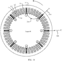
- FIG. 1 shows the six-phase motor 100 according to an embodiment of this application.
- the six-phase motor 100 includes at least: the six-phase flat wire wave winding structure and a stator iron core 10.
- a plurality of stator slots 11 are disposed in an inner wall of the stator iron core 10 in a circumferential direction. Two ends of the stator slot 11 separately extend along an axial direction of the stator iron core 10 to two end surfaces of the stator iron core 10.
- FIG. 2 is a schematic diagram of a cross section of the six-phase motor 100 according to this application.
- FIG. 3 is a schematic diagram of an enlarged part in FIG. 2 .
- the six-phase flat wire wave winding structure includes a six-phase flat wire wave winding 20, and the six-phase flat wire wave winding 20 includes a U-phase wave winding 21, a V-phase wave winding 22, a W-phase wave winding 23, an A-phase wave winding 24, a B-phase wave winding 25, and a C-phase wave winding 26.
- the six-phase flat wire wave winding 20 includes two symmetrical three-phase wave windings.
- the U-phase wave winding 21, the V-phase wave winding 22, and the W-phase wave winding 23 may be one three-phase wave winding.
- the A-phase wave winding 24, the B-phase wave winding 25, and the C-phase wave winding 26 may be the other three-phase wave winding.
- the two three-phase wave windings are disposed symmetrically, and a difference between electrical angles of the two three-phase wave windings is 30 degrees. To be specific, phases of the two three-phase wave windings are different.
- Some existing six-phase motors 100 include two three-phase wave windings that have same phases and that are connected in parallel or in series. However, a motor with this structure is essentially a dual three-phase winding motor, rather than a six-phase winding motor, and harmonic cannot be counteracted. However, the six-phase motor 100 provided in this embodiment of this application includes two three-phase wave windings with different phases, and harmonic can be counteracted.
- the six-phase motor 100 in FIG. 2 in this embodiment of this application is described by using an 8-pole motor as an example. That is, the six-phase motor 100 shown in FIG. 2 has eight poles and four pole pairs, and each pole pair includes an N pole and an S pole. Therefore, as shown in FIG. 2 and FIG. 3 , the six-phase flat wire wave winding 20 in each pole is sequentially wound in the stator slot 11.
- each stator slot 11 has 2M layers of an in-phase wave winding, and the wave windings in the stator slots 11 have a same quantity of layers.
- M 2M layers of an in-phase wave winding
- the wave windings in the stator slots 11 have a same quantity of layers.
- M 2M layers of an in-phase wave winding
- M 2M layers of an in-phase wave winding
- each stator slot 11 has four layers of in-phase wave windings
- each of the stator slots 11 has four layers of the wave winding.
- each stator slot 11 has an even number of layers.
- one of the stator slots 11 has four layers of a U-phase wave winding 21.
- the four layers of the U-phase wave winding 21 are respectively an L1 layer, an L2 layer, an L3 layer, and an L4 layer, and the wave winding in the L1 layer, the L2 layer, the L3 layer, and the L4 layer is the U-phase wave winding 21. Therefore, as shown in FIG. 5 , an insulation layer does not need to be disposed between two adjacent layers of the wave winding in the same stator slot 11.
- Each phase of wave winding has a wire-in end and a wire-out end.
- the U-phase wave winding 21 has a wire-in end 21a (namely, U+) and a wire-out end 21b (namely, U-);
- the V-phase wave winding 22 has a wire-in end 22a (namely, V+) and a wire-out end 22b (namely, V-);
- the W-phase wave winding 23 has a wire-in end 23a (namely, W+) and a wire-out end 23b (namely, W-);
- the A-phase wave winding 24 has a wire-in end 24a (namely, A+) and a wire-out end 24b (namely, A-);
- the B-phase wave winding 25 has a wire-in end 25a (namely, B+) and a wire-out end 25b (namely, B-);
- the C-phase wave winding 26 has a wire-in end 26a (namely, C+) and a wire-out end 26
- the wire of each phase of wave winding forms an effective edge 20b and two end portions of the six-phase flat wire wave winding 20.
- the six-phase flat wire wave winding 20 includes the effective edge 20b and the two end portions.
- the two end portions are respectively a first end portion 20a and a second end portion 20c.
- the effective edge 20b is located in the stator slot 11.
- the first end portion 20a and the second end portion 20c are located outside the stator slot 11 and are respectively located on two ends of the effective edge 20b.
- the U-phase wire 21c includes a U-phase effective edge 212c and two U-phase end portions.
- the two U-phase end portions are respectively a first U-phase end portion 211c and a second U-phase end portion 213c.
- the U-phase effective edge 212c is located in each stator slot 11 corresponding to the U-phase wave winding 21.
- the first U-phase end portion 211c and the second U-phase end portion 213c are respectively located on two ends of the U-phase effective edge 212c.
- the wire-in end and the wire-out end of each phase of wave winding are both located at a bottom of the stator slot 11.
- the wave winding in the L 1 layer in the stator slot 11 is located at the bottom of the stator slot 11 (as shown in FIG. 5 ). Therefore, the wire-in end of the wave winding is led in from the L1 layer in one of the stator slots 11, and the wire-out end of the wave winding is led out from the L1 layer of another stator slot 11.
- the wire-in end and the wire-out end of each phase of wave winding are both located at an opening of the stator slot 11.
- the wave winding in the L4 layer in the stator slot 11 is located at the opening of the stator slot 11 (as shown in FIG. 5 ). Therefore, the wire-in end of the wave winding is led in from the L4 layer in one of the stator slots 11, and the wire-out end of the wave winding is led out from the L4 layer of another stator slot 11.
- the wire-in end 21a of the U-phase wave winding 21 is led in from the L1 layer of the seventh stator slot 11, and the wire-out end 21b of the U-phase wave winding 21 is led out from the L1 layer of the 13th stator slot 11.
- the wire-in end 21a and the wire-out end 21b of the U-phase wave winding 21 are both located at the bottom of the stator slot 11.
- the wire-in end and the wire-out end of each phase of wave winding are both located at the opening or the bottom of the stator slot 11, to facilitate connection of an end portion of a led-out wire.
- each phase of wave winding includes a branch windings.
- each phase of wave winding may include one branch winding, or each phase of wave winding may include two or more branch windings.
- the two or more branch windings in each phase of branch winding are connected in parallel.
- Each phase of branch winding is wound in Pq stator slots 11. Therefore, for the six-phase flat wire wave winding, a total quantity of the stator slots 11 is 6Pq.
- P is a quantity of poles of the motor.
- a value of P is specifically selected based on an actual requirement. For example, P may be 8, 6, or 4.
- q is a quantity of slots of each phase of wave winding in each pole, and q and a may be positive integers such as 1, 2, or 3.
- each phase of branch winding is wound in eight stator slots 11, and the total quantity of the stator slots 11 is 48.
- the 48 stator slots 11 are separately numbered.
- the 48 stator slots 11 are numbered by using numbers 1 to 48.
- the eight stator slots 11 in which the U-phase wave winding 21 is wound are respectively the first slot, the seventh slot, the 13th slot, the 19th slot, the 25th slot, the 31st slot, the 37th slot, and the 43rd slot.
- the wire-in end 21a of the U-phase wave winding 21 is led in from the L1 layer of the seventh slot, and after winding in four layers in the foregoing eight slots, the wire-out end 21b of the U-phase wave winding 21 is led out from the L1 layer of the 13th slot.
- the six-phase motor 100 is an eight-pole motor (that is, a quantity P of poles of the motor is 8), and a quantity q of slots of each phase in each pole is 1, that is, in each magnetic pole, each phase of wave winding is wound in one stator slot 11.
- the 48 stator slots 11 are respectively represented by S1 to S48 in Table 1, or represented by numbers 1 to 48 in FIG. 6 .
- a quantity of layers of each phase of wave winding in the stator slot 11 is 2M.
- X i is defined as an ith layer of an Xth slot
- a winding manner of any phase of wave winding is: X 3 ⁇ X + 6 ⁇ 1 4 ⁇ X + 6 ⁇ 2 3 ⁇ X + 6 ⁇ 3 4 ⁇ ⁇ X + 6 ⁇ P ⁇ 1 4 ⁇ ...
- each phase of wave winding in each pole is wound in 2M layers in a same stator slot 11
- the wave winding is first wound in odd-numbered layers in the same stator slot 11, then wound in even-numbered layers in the same stator slot, and quantities of layers in which each phase of wave winding is wound in stator slots of two adjacent poles are different. For example, after winding is performed in the L 1 layer in the Xth slot, winding is performed in the L2 layer in an (X+6)th slot, and then winding is performed in the L1 layer in an (X+12)th slot.
- Each stator slot 11 has four layers of the wave winding.
- the L1 layer of the wave winding is located at the bottom of the stator slot 11, the L4 layer is close to the opening of the stator slot 11, the L1 layer is the first layer, L2 is the second layer, L3 is the third layer, and L4 is the fourth layer.
- the six-phase flat wire wave winding 20 includes the U-phase wave winding, the V-phase wave winding, the W-phase wave winding, the A-phase wave winding, the B-phase wave winding, and the C-phase wave winding, where"+" in Table 1 represents current inflow into a conductor, and "-" represents current outflow from a conductor.
- a winding manner of any phase of wave winding is: X 1 ⁇ X + 6 ⁇ 1 2 ⁇ X + 6 ⁇ 2 1 ⁇ X + 6 ⁇ 3 2 ⁇ ⁇ X + 6 ⁇ P ⁇ 1 2 ⁇ X 3 ⁇ X + 6 ⁇ 1 4 ⁇ X + 6 ⁇ 2 3 ⁇ X + 6 ⁇ 3 4 ⁇ ⁇ X + 6 ⁇ P ⁇ 1 4 ⁇ X 4 ⁇ X + 6 ⁇ P ⁇ 1 3 ⁇ X + 6 ⁇ P ⁇ 2 4 ⁇ X + 6 ⁇ P ⁇ 3 3 ⁇ X + 6 ⁇ 1 3 ⁇ X 2 ⁇ X + 6 ⁇ P ⁇ 3 3 ⁇ X + 6 ⁇ P ⁇ 1 3 ⁇ X 2 ⁇ X + 6 ⁇ P ⁇ 1 1 1 ⁇ X + 6 ⁇ P ⁇ 2 2 ⁇ X + 6 ⁇ P ⁇ 3 1 ⁇ X + 6 ⁇ P ⁇ 1
- winding when any phase of wave winding is first wound in one layer in corresponding P slots, winding may be: X 1 ⁇ X + 6 ⁇ 1 2 ⁇ X + 6 ⁇ 2 1 ⁇ X + 6 ⁇ 3 2 ⁇ ⁇ X + 6 ⁇ P ⁇ 1 2
- winding may be: X 3 ⁇ X + 6 ⁇ 1 4 ⁇ X + 6 ⁇ 2 3 ⁇ X + 6 ⁇ 3 4 ⁇ ⁇ X + 6 ⁇ P ⁇ 1 4
- winding may be: X 4 ⁇ X + 6 ⁇ P ⁇ 1 3 ⁇ X + 6 ⁇ P ⁇ 2 4 ⁇ X + 6 ⁇ P ⁇ 3 3 ⁇ ⁇ X + 6 ⁇ 1 3
- winding may be: X 2 ⁇ X + 6 ⁇ P ⁇ 1 1 ⁇ X + 6 ⁇ P ⁇ 2 2 ⁇ X + 6 ⁇ P ⁇ 3 1 ⁇ ⁇ X + 6 ⁇ 1 1
- any phase of wave winding completes winding in four layers in the stator slots 11.
- each phase of wave winding is wound in eight slots, and a winding manner of any phase of wave winding is: X 1 ⁇ X + 6 2 ⁇ X + 12 1 ⁇ X + 18 2 ⁇ X + 24 1 ⁇ X + 30 2 ⁇ X + 36 1 ⁇ X + 42 2 ⁇ X 3 ⁇ X + 6 4 ⁇ X + 12 3 ⁇ X + 18 4 ⁇ X + 24 3 ⁇ X + 30 4 ⁇ X + 36 3 ⁇ X + 42 4 ⁇ X 4 ⁇ X + 42 3 ⁇ X + 36 4 ⁇ X + 30 3 ⁇ X + 24 4 ⁇ X + 18 3 ⁇ X + 12 4 ⁇ X + 6 3 ⁇ X 2 ⁇ X + 42 1 ⁇ X + 36 2 ⁇ X + 30 1 ⁇ X + 24 2 ⁇ X + 18 1 ⁇ X + 12 2 ⁇ X + 30 1 ⁇ X + 24 2 ⁇ X + 18
- winding is: the L3 layer in the first slot, the L4 layer in the seventh slot, the L3 layer in the 13th slot, the L4 layer in the 19th slot, the L3 layer in the 25th slot, the L4 layer in the 31st slot, the L3 layer in the 37th slot, and the L4 layer in the 43rd slot.
- winding is: the L4 layer in the first slot, the L3 layer in the 43rd slot, the L4 layer in the 37th slot, the L3 layer in the 31st slot, the L4 layer in the 25th slot, the L3 layer in the 19th slot, the L4 layer in the 13th slot, and the L3 layer in the seventh slot.
- winding is: the L2 layer in the first slot, the L1 layer in the 43rd slot, the L2 layer in the 37th slot, the L1 layer in the 31st slot, the L2 layer in the 25th slot, the L1 layer in the 19th slot, the L2 layer in the 13th slot, and the L1 layer in the seventh slot.
- the U-phase wave winding 21 may be wound starting from the seventh slot, and the eight stator slots 11 in which the U-phase wave winding 21 is wound are respectively: the seventh slot, the 13th slot, the 19th slot, the 25th slot, the 31st slot, the 37th slot, the 43rd slot, and the 49th slot. In this embodiment of this application, because there are 48 stator slots 11, the 49th slot is the first slot.
- winding may be performed along a clockwise arrow direction in FIG. 8 , namely, in ascending order of slot numbers.
- FIG. 8 for a winding sequence: the L1 layer of the seventh slot, the L2 layer of the 13th slot, the L1 layer of the 19th slot, the L1 layer of the 25th slot, the L1 layer of the 31st slot, the L1 layer of the 37th slot, the L1 layer of the 43rd slot, and the L2 layer of the first slot.
- winding continues to be performed along the clockwise arrow direction, and the winding sequence is: the L3 layer of the seventh slot, the L4 layer of the 13th slot, the L3 layer of the 19th slot, the L4 layer of the 25th slot, the L3 layer of the 31st slot, the L4 layer of the 37th slot, the L3 layer of the 43rd slot, and the L4 layer of the first slot.
- winding is performed along an anticlockwise arrow direction, namely, in descending order of slot numbers, and the winding sequence is: the L4 layer of the seventh slot, the L3 layer of the first slot, the L4 layer of the 43rd slot, the L3 layer of the 37th slot, the L4 layer of the 31st slot, the L3 layer of the 25th slot, the L4 layer of the 19th slot, and the L3 layer of the 13th slot.
- the wire-in end 21a and the wire-out end 21b of the U-phase wave winding 21 are both located at the bottom of the stator slot 11, to be specific, are led in and led out both from the L1 layer, to facilitate connection of an end portion of a led-out wire.
- each phase of wave winding has a jumper.
- One end of the jumper is connected to the (2M)th layer of winding in the [X+6 ⁇ (P-1)]th slot, and the other end of the jumper is connected to the (2M)th layer of winding in the Xth slot.
- the U-phase wave winding 21 has a jumper 21d, and two ends of the jumper 21d are respectively connected to the L4 layer of the seventh slot and the L4 layer of the first slot.
- a span of the jumper of each phase of wave winding is y, and y is 6q.
- a quantity q of the slots of each phase of wave winding in each pole is 1. Therefore, as shown in FIG. 7 , the span y of the jumper 21d is 6.
- the wire-in ends and the wire-out ends of the phases of wave windings are close to each other, and the wire-out ends of the phases of wave windings have a same twist angle (namely, a bending angle).
- the wire-out ends of the phases of wave windings can be directly led out in parallel, or led out by using a copper busbar (busbar).
- busbar copper busbar
- the wire-in ends and the wire-out ends of the six-phase flat wire wave winding 20 may use a star connection manner in which a neutral point is shared, as shown in FIG. 12 , or may use a star connection manner in which a neutral point is not shared, as shown in FIG. 13 , or may use a triangular connection manner in FIG. 14 .
- wiring of the phases of the wave windings is flexible, and may be selected based on a design requirement.
- a winding manner of any phase of wave winding is: X 1 ⁇ X + 6 ⁇ 1 2 ⁇ X + 6 ⁇ 2 1 ⁇ X + 6 ⁇ 3 2 ... ⁇ X + 6 ⁇ P ⁇ 1 2 ⁇ X 3 ⁇ X + 6 ⁇ 1 4 ⁇ X + 6 ⁇ 2 3 ⁇ X + 6 ⁇ 3 4 ... ⁇ X + 6 ⁇ P ⁇ 1 4 ⁇ X 5 ⁇ X + 6 ⁇ 1 6 ⁇ X + 6 ⁇ 2 5 ⁇ X + 6 ⁇ 3 6 ... ⁇ X + 6 ⁇ P ⁇ 1 6 ⁇ X 6 ⁇ X + 6 ⁇ P ⁇ 1 5 ⁇ X + 6 ⁇ P ⁇ 2 6 ⁇ X + 6 ⁇ P ⁇ 3 5 ... ⁇ X + 6 ⁇ 1 5 ⁇ X + 6 ⁇ P ⁇ 2 6 ⁇ X + 6 ⁇ P ⁇ 3 5 ... ⁇ X + 6 ⁇
- a winding manner of any phase of wave winding is: X 1 ⁇ X + 6 ⁇ 1 2 ⁇ X + 6 ⁇ 2 1 ⁇ X + 6 ⁇ 3 2 ⁇ X + 6 ⁇ 4 1 ⁇ X + 6 ⁇ 5 2 ⁇ X + 6 ⁇ 6 1 ⁇ X + 6 ⁇ 7 2 ⁇ X 3 ⁇ X + 6 ⁇ 1 4 ⁇ X + 6 ⁇ 2 3 ⁇ X + 6 ⁇ 3 4 ⁇ X + 6 ⁇ 4 3 ⁇ X + 6 ⁇ 5 4 ⁇ X + 6 ⁇ 6 3 ⁇ X + 6 ⁇ 7 4 ⁇ X 5 ⁇ X + 6 ⁇ 1 6 ⁇ X + 6 ⁇ 2 5 ⁇ X + 6 ⁇ 3 6 ⁇ X + 6 ⁇ 4 5 ⁇ X + 6 ⁇ 5 6 ⁇ X + 6 ⁇ 6 5 ⁇ X + 6 ⁇ 6 5 ⁇ X + 6 ⁇ 7 6 ⁇ X 6 ⁇
- quantities of winding layers of each stator slot 11 include but are not limited to four and six, or may be two, eight, or the like. Refer to the winding manner of four layers and six layers for the winding manner.
- each phase of wave winding has conductors in all layers of a same stator slot, and the wave windings are uniformly and symmetrically distributed. Potentials of branches are balanced, and there is no loop current. Conductors in different layers of a same slot are in-phase, and do not need to be isolated by insulating paper. This helps improve a slot fill factor and reduce costs. In addition, problems that a flat wire winding process is highly difficult and manufacturing costs are high due to an increase in a quantity of phases of the six-phase motor are effectively resolved.
- the 72 stator slots 11 are respectively represented by S1 to S72 in Table 2, or represented by numbers 1 to 72 in FIG. 15 .
- a quantity of layers of each phase of wave winding in the stator slot 11 is 2M.
- X i is defined as an ith layer of an Xth slot, and a winding manner of any phase of wave winding is: X 1 ⁇ X + 12 ⁇ 1 2 ⁇ X + 12 ⁇ 2 1 ⁇ X + 12 ⁇ 3 2 ... ⁇ X + 12 ⁇ P ⁇ 1 2 ⁇ X 3 ⁇ X + 12 ⁇ 1 4 ⁇ X + 12 ⁇ 2 3 ⁇ X + 12 ⁇ 3 4 ... ⁇ X + 12 ⁇ P ⁇ 1 4 ⁇ ... X 2 M ⁇ 1 ⁇ X + 12 ⁇ 1 2 M ⁇ X + 12 ⁇ 2 2 M ⁇ 1 ⁇ X + 12 ⁇ 3 2 M ... ⁇ X + 12 ⁇ P ⁇ 1 2 M ⁇ X 2 M ⁇ 1 ⁇ X + 12 ⁇ 3 2 M ... ⁇ X + 12 ⁇ P ⁇ 1 2 M
- each phase of wave winding first forms a first coil in one of the stator slots 11 in each pole based on the winding manner in the foregoing Embodiment 1, and then, each phase of wave winding forms a second coil in the other stator slot 11 in each pole based on the winding manner in Embodiment 1.
- the first coil is connected in series to the second coil.
- a difference between phases of the first coil and the second coil is 30/q degrees.
- each stator slot 11 has four layers of the wave winding.
- a winding manner in which any phase of wave winding is wound in four layers in the stator slot 11 is: X 1 ⁇ X + 12 ⁇ 1 2 ⁇ X + 12 ⁇ 2 1 ⁇ X + 12 ⁇ 3 2 ... ⁇ X + 12 ⁇ P ⁇ 1 2 ⁇ X 3 ⁇ X + 12 ⁇ 1 4 ⁇ X + 12 ⁇ 2 3 ⁇ X + 12 ⁇ 3 4 ... ⁇ X + 12 ⁇ P ⁇ 1 4 ⁇ X 4 ⁇ X + 12 ⁇ P ⁇ 1 3 ⁇ X + 12 ⁇ P ⁇ 2 4 ⁇ X + 12 ⁇ P ⁇ 3 3 ... ⁇ X + 12 ⁇ 1 3 ⁇ X 2 ⁇ X + 12 ⁇ P ⁇ 1 1 1 ⁇ X + 12 ⁇ P ⁇ 2 2 ⁇ X + 12 ⁇ P ⁇ 3 1 ... ⁇ X + 12 ⁇ 1 3 ⁇
- each phase of wave winding in each pole is wound in two adjacent stator slots 11, and a winding manner in which any phase of wave winding is wound in four layers is: X 1 ⁇ X + 12 2 ⁇ X + 24 1 ⁇ X + 36 2 ⁇ X + 48 1 ⁇ X + 60 2 ⁇ X 3 ⁇ X + 12 4 ⁇ X + 24 3 ⁇ X + 36 4 ⁇ X + 48 3 ⁇ X + 60 4 ⁇ X 4 ⁇ X + 60 3 ⁇ X + 48 4 ⁇ X + 36 3 ⁇ X + 24 4 ⁇ X + 12 3 ⁇ X 2 ⁇ X + 60 1 ⁇ X + 48 2 ⁇ X + 36 1 ⁇ X + 24 2 ⁇ X + 36 1 ⁇ X + 24 2 ⁇ X + 12 1 ⁇ X + 1 1 ⁇ X + 1 + 12 2 ⁇ X + 1 + 24 1 ⁇ X + 1 + 36 2 ⁇ X + 1 + 36 2
- the B-phase wave winding 25 when the B-phase wave winding 25 is wound, X is 11, that is, the wire-in end 25a of the B-phase wave winding 25 starts from the L1 layer of the 11th slot, and the B-phase wave winding 25 is wound in two adjacent layers in each pole.
- the B-phase wave winding 25 is separately wound in: the 11th slot and the 12th slot, the 23rd slot and the 24th slot, the 35th slot and the 36th slot, the 47th slot and the 48th slot, the 59th slot and the 60th slot, and the 71st slot and the 72nd slot.
- the B-phase wave winding 25 is wound in two layers in one of the stator slots 11 of each pole, and then, along an opposite direction, is wound in last two layers in the stator slot 11, to form the first coil. Then, the B-phase wave winding 25 is wound starting from the L1 layer of the 12th slot, that is, the B-phase wave winding 25 is first wound in two layers in the other adjacent stator slot 11 of each pole, and then, along an opposite direction, is wound in last two layers in the adjacent stator slot 11, to form the second coil. The first coil is connected in series to the second coil to form the B-phase wave winding 25 shown in FIG. 16 .
- Each phase of wave winding has a first jumper 251d, a second jumper 252d, and a third jumper 253d. That is, each phase of wave winding has three jumpers. Two ends of the first jumper 251d are respectively connected to a (2M)th layer of an [X+12 ⁇ (P-1)]th slot and a (2M)th layer of an Xth slot, two ends of the second jumper 252d are respectively connected to the first layer of an (X+12)th slot and the first layer of an (X+1)th slot, and two ends of the third jumper 253d are respectively connected to an (2M)th layer of an [X+1+12 ⁇ (P-1)]th slot and a (2M)th layer of the (X+1)th slot.
- the B-phase wave winding 25 has the first jumper 251d, the second jumper 252d, and the third jumper 253d.
- the two ends of the first jumper 251d are respectively connected to the L4 layer of the 71st slot and the L4 layer of the 11th slot
- the two ends of the second jumper 252d are respectively connected to the L1 layer of the 23rd slot and the L1 layer of the 12th slot
- the two ends of the third jumper 253d are respectively connected to the L4 layer of the 72nd slot and the L4 layer of the 12th slot.
- a span of the first jumper 251d is y
- a span of the second jumper 252d is y-1
- the wire-in ends and the wire-out ends of the phases of wave windings are close to each other, and the wire-out ends of the phases of wave windings have a same twist angle (namely, a bending angle).
- the wire-out ends of the phases of wave windings can be directly led out in parallel, or led out by using a copper busbar (busbar).
- busbar copper busbar
- the wire includes an effective edge 212c and two B-phase end portions.
- the two B-phase end portions are respectively a first B-phase end portion 211c and a second B-phase end portion 213c.
- the effective edge 212c is located in the stator slots 11 corresponding to the B-phase wave winding 25 (for example, the 11th slot and the 12th slot, the 23rd slot and the 24th slot, the 35th slot and the 36th slot, the 47th slot and the 48th slot, the 59th slot and the 60th slot, and the 71st slot and the 72nd slot).
- the first B-phase end portion 211c and the second B-phase end portion 213c are separately located outside the stator slots 11, and the first B-phase end portion 211c and the second B-phase portion 213c are respectively located on two ends of the effective edge 212c.
- Each phase of wave winding is wound in 2M layers in one of the stator slots 11 of each pole, to form the first coil, and each phase of wave winding is wound in 2M layers in the other stator slot 11 of each pole, to form the second coil.
- the first coil is connected in series to the second coil by using the second jumper 252d.
- the B-phase wave winding 25 is separately wound in four layers in the 11th slot, the 23rd slot, the 35th slot, the 47th slot, the 59th slot, and the 71st slot, to form the first coil
- the B-phase wave winding 25 is separately wound in four layers in the 12th slot, the 24th slot, the 36th slot, the 48th slot, the 60th slot, and the 72nd slot, to form the second coil.
- the winding manner of the second coil is the same as that of the first coil.
- the second coil performs overall translation by one stator slot 11, and the first coil is connected in series to the second coil by using the second jumper 252d.
- a difference between phases of the first coil and the second coil is 30/q degrees.
- winding is performed in six layers in each stator slot, which may be respectively an L1 layer, an L2 layer, an L3 layer, an L4 layer, an L5 layer (not shown), and an L6 layer (not shown), and a winding manner of any phase of wave winding is: X 1 ⁇ X + 12 ⁇ 1 2 ⁇ X + 12 ⁇ 2 1 ⁇ X + 12 ⁇ 3 2 ... ⁇ X + 12 ⁇ P ⁇ 1 2 ⁇ X 3 ⁇ X + 12 ⁇ 1 4 ⁇ X + 12 ⁇ 2 3 ⁇ X + 12 ⁇ 3 4 ... ⁇ X + 12 ⁇ P ⁇ 1 4 ⁇ X 5 ⁇ X + 12 ⁇ 1 6 ⁇ X + 12 ⁇ 2 5 ⁇ X + 12 ⁇ 3 6 ... ⁇ X + 12 ⁇ P ⁇ 1 6 ⁇ X 6 ⁇ X + 12 ⁇ P ⁇ 1 5 ⁇ X + 12 ⁇ P ⁇ 1 5 ⁇ X + 12
- a winding manner of any phase of wave winding is: X 1 ⁇ X + 12 ⁇ 1 2 ⁇ X + 12 ⁇ 2 1 ⁇ X + 12 ⁇ 3 2 ⁇ X + 12 ⁇ 4 1 ⁇ X + 12 ⁇ 5 2 ⁇ X 3 ⁇ X + 12 ⁇ 1 4 ⁇ X + 12 ⁇ 2 3 ⁇ X + 12 ⁇ 3 4 ⁇ X + 12 ⁇ 4 3 ⁇ X + 12 ⁇ 5 4 ⁇ X 5 ⁇ X + 12 ⁇ 1 6 ⁇ X + 12 ⁇ 2 5 ⁇ X + 12 ⁇ 3 6 ⁇ X + 12 ⁇ 4 5 ⁇ X + 12 ⁇ 5 6 ⁇ X + 12 ⁇ 2 5 ⁇ X + 12 ⁇ 3 6 ⁇ X + 12 ⁇ 4 5 ⁇ X + 12 ⁇ 5 6 ⁇ X 6 ⁇ X + 12 ⁇ 5 5 ⁇ X + 12 ⁇ 4 6 ⁇ X + 12 ⁇ 3 5 ⁇
- Each phase of wave winding is wound in six layers in one of the stator slots 11 of each pole to form the first coil, and each phase of wave winding is wound in six layers in the other adjacent stator slot 11 of each pole to form the second coil.
- the first coil is connected in series to the second coil by using the second jumper 252d.
- quantities of winding layers of each stator slot 11 include but are not limited to four and six, or may be two, eight, or the like. Refer to the winding manner of four layers and six layers for the winding manner.
- the U-phase wave winding 21 includes a first U-phase branch winding 211 (namely, U1) and a second U-phase branch winding 212 (namely, U2)
- the V-phase wave winding 22 includes a first V-phase branch winding 221 (namely, VI) and a second V-phase branch winding 222 (namely, V2)
- the W-phase wave winding 23 includes a first W-phase branch winding 231 (namely, W1) and a second W-phase branch winding 232 (namely, W2)
- the A-phase wave winding 24 includes a first A-phase branch winding 241 (namely, A1) and a second A-phase branch winding 242 (namely, A2)
- the B-phase wave winding 25 includes a first B-phase branch winding 251 (namely, B1) and a second B-phase branch winding 252 (namely, B2)
- the C-phase wave winding 26 includes a first C-phase branch winding 261 (namely, C1) and a second C-phase branch wind
- Each of the first branch winding and the second branch winding of each phase in each pole has two slots.
- each stator slot 11 has the first branch winding and the second branch winding that are in-phase and that have a same quantity of layers.
- the first branch winding and the second branch winding are alternately arranged in a same stator slot 11.
- the two branch windings in each phase of each pole jointly multiplex two stator slots 11.
- a quantity of layers of the first branch winding and a quantity of layers of the second branch winding may both be 2M.
- the other two layers of the first branch winding are located in the L2 layer and the L4 layer of the adjacent stator slot 11, and the L1 layer and the L3 layer of the adjacent stator slot 11 may be the other two layers in which the second branch winding is wound.
- the four layers of the first branch winding are uniformly distributed in two adjacent stator slots 11.
- each stator slot 11 has two layers of the first branch winding and two layers of the second branch winding, and the two layers of the first branch winding and the two layers of the second branch winding are alternately arranged.
- first branch winding and the second branch winding are alternately arranged in a same stator slot 11 specifically means that, the L1 layer of the stator slot 11 may be the first branch winding, the L2 layer of the stator slot 11 may be the second branch winding, the L3 layer of the stator slot 11 may be the first branch winding, and the L4 layer of the stator slot 11 may be the second branch winding.
- two adjacent layers in a same stator slot 11 are two different branch windings of a same phase of wave winding.
- the first branch winding and the second branch winding are alternately arranged in a same stator slot 11.
- two parallel branch windings of each phase of wave winding are uniformly and symmetrically distributed in the layers of the same stator slot 11, and potentials of the branch windings of each phase of wave winding are balanced, to avoid generation of a loop current, and reduce losses, thereby improving efficiency of the motor.
- a winding manner of a first branch winding in any phase of wave winding is: X 1 ⁇ X + 12 ⁇ 1 2 ⁇ X + 12 ⁇ 2 1 ⁇ X + 12 ⁇ 3 2 ... ⁇ X + 12 ⁇ P ⁇ 1 2 ⁇ X 3 ⁇ X + 12 ⁇ 1 4 ⁇ X + 12 ⁇ 2 3 ⁇ X + 12 ⁇ 3 4 ... ⁇ X + 12 ⁇ P ⁇ 1 4 ⁇ ... X 2 M ⁇ 1 ⁇ X + 12 ⁇ 1 2 M ⁇ X + 12 ⁇ 2 2 M ⁇ 1 ⁇ X + 12 ⁇ 3 2 M ... ⁇ X + 12 ⁇ P ⁇ 1 2 M ⁇ X + 1 2 M ⁇ X + 1 + 12 ⁇ P ⁇ 2 M ⁇ X + 1 + 12 ⁇ P ⁇ 1 2 M ⁇ 1 ⁇ X + 1 + 12 ⁇ P ⁇ 2 2 M ⁇ 1 + 12 ⁇ P ⁇ 2 M ⁇
- X is less than 13
- the first branch winding of each phase of wave winding is wound in M layers in one of the stator slots of each pole to form a third coil
- the first branch winding of each phase of wave winding is wound in M layers in the other adjacent stator slot of each pole to form a fourth coil
- the third coil is connected in series to the fourth coil
- a difference between phases of the third coil and the fourth coil is 30/q degrees.
- a winding manner of a second branch winding in any phase of wave winding is: X + 1 1 ⁇ X + 1 + 12 ⁇ 1 2 ⁇ X + 1 + 12 ⁇ 2 1 ⁇ X + 1 + 12 ⁇ 3 2 ... ⁇ X + 1 + 12 ⁇ P ⁇ 1 2 ⁇ X + 1 3 ⁇ X + 1 + 12 ⁇ 1 4 ⁇ X + 1 + 12 ⁇ 2 3 ⁇ X + 1 + 12 ⁇ 3 4 ... ⁇ X + 1 + 12 ⁇ P ⁇ 1 4 ⁇ ... X + 1 2 M ⁇ 1 ⁇ X + 1 + 12 ⁇ 1 2 M ⁇ X + 12 ⁇ 2 2 M ⁇ 1 ⁇ X + 12 ⁇ 3 2 M ... ⁇ X + 12 ⁇ P ⁇ 1 2 M ⁇ X 2 M ⁇ 1 ⁇ X + 12 ⁇ 3 2 M ... ⁇ X + 12 ⁇ P ⁇ 1 2 M ⁇ X 2 M ⁇ X + 12
- the second branch winding of each phase of wave winding is wound in M layers in one of the stator slots of each pole to form a fifth coil
- the second branch winding of each phase of wave winding is wound in M layers in the other adjacent stator slot of each pole to form a sixth coil
- the fifth coil is connected in series to the sixth coil, and a difference between phases of the sixth coil and the fifth coil is 30/q degrees.
- each phase of wave winding is wound in four layers in the stator slot 11, and the first branch winding in any phase of wave winding may be wound starting from an Xth slot (X is less than 13), and a winding manner is as follows: X 1 ⁇ X + 12 ⁇ 1 2 ⁇ X + 12 ⁇ 2 1 ⁇ X + 12 ⁇ 3 2 ⁇ ⁇ X + 12 ⁇ P ⁇ 1 2 ⁇ X 3 ⁇ X + 12 ⁇ 1 4 ⁇ X + 12 ⁇ 2 3 ⁇ X + 12 ⁇ 3 4 ⁇ ⁇ X + 12 ⁇ P ⁇ 1 4 ⁇ X + 1 4 ⁇ X + 1 + 12 ⁇ P ⁇ 1 4 ⁇ X + 1 4 ⁇ X + 1 + 12 ⁇ P ⁇ 1 3 ⁇ X + 1 + 12 ⁇ P ⁇ 2 4 ⁇ X + 1 + 12 ⁇ P ⁇ 3 3 ⁇ X + 1 + 12 ⁇ P ⁇ 3 3 ⁇ X + 1 + 12 ⁇
- the first branch winding is first wound in two layers in one of the stator slots 11 of each pole, to form the third coil, and is then wound in other two layers in the other stator slot 11 of each pole, to form the fourth coil.
- the third coil is connected in series to the fourth coil.
- a difference between phases of the third coil and the fourth coil is 30/q degrees.
- the second branch winding in any phase of wave winding may be wound starting from an (X+1)th slot (X is less than 13), and a winding manner is: X + 1 1 ⁇ X + 1 + 12 ⁇ 1 2 ⁇ X + 1 + 12 ⁇ 2 1 ⁇ X + 1 + 12 ⁇ 3 2 ⁇ ⁇ X + 1 + 12 ⁇ P ⁇ 1 2 ⁇ X + 1 3 ⁇ X + 1 + 12 ⁇ 1 4 ⁇ X + 1 + 12 ⁇ 2 3 ⁇ X + 1 + 12 ⁇ 3 4 ⁇ ⁇ X + 1 + 12 ⁇ P ⁇ 1 4 ⁇ X 4 ⁇ X + 12 ⁇ P ⁇ 1 3 ⁇ X + 12 ⁇ P ⁇ 2 4 ⁇ X + 12 ⁇ P ⁇ 3 3 ⁇ X + 12 ⁇ 1 3 ⁇ X 2 ⁇ X + 12 ⁇ P ⁇ 3 3 ⁇ X + 12 ⁇ P ⁇ 1 1 3 ⁇ X 2 ⁇ X + 12
- the second branch winding is first wound in two layers in one of the stator slots 11 of each pole, to form the fifth coil, and is then wound in other two layers in the other stator slot 11 of each pole, to form the sixth coil.
- the fifth coil is connected in series to the sixth coil.
- a difference between phases of the fifth coil and the sixth coil is 30/q degrees.
- the first branch winding of each phase of wave winding has a fourth jumper 254d
- the second branch winding of each phase of wave winding has a fifth jumper 255d.
- Two ends of the fourth jumper 254d are respectively connected to a (2M)th layer of an [X+12 ⁇ (P-1)]th slot and an (2M)th layer of the (X+1)th slot
- two ends of the fifth jumper 255d are respectively connected to a (2M)th layer of an [X+1+12 ⁇ (P-1)]th slot and an (2M)th layer of the Xth slot.
- a span of the fourth jumper 254d is y+1
- a span of the fifth jumper 255d is y-1
- y is 6q.
- Spans between welding ends and non-welding ends of coils of phases of wave windings are equal and are all y. To be specific, the spans between welding ends and non-welding ends of the coils of the phases of wave windings are equal and are all 12.
- the third coil is connected in series to the fourth coil by using the fourth jumper 254d
- the fifth coil is connected in series to the sixth coil by using the fifth jumper 255d.
- the B-phase wave winding 25 includes a first B-phase branch winding 251 and a second B-phase branch winding 252. That is, the B-phase wave winding 25 includes a B1-phase branch winding and a B2-phase branch winding.
- the first B-phase branch winding 251 includes a wire-in end B1+ and a wire-out end B1-.
- the wire 2511c may include two end portions and an effective edge that are located in the stator slots 11 (as shown in FIG. 16 ).
- the wire 2511c may include the foregoing third coil and fourth coil. The third coil is connected in series to the fourth coil by using the fourth jumper 254d.
- the second B-phase branch winding 252 includes a wire-in end B2+ and a wire-out end B2-, and there is a wire 2521c between the wire-in end B2+ and the wire-out end B2-.
- the wire 2521c includes the fifth coil and the sixth coil.
- the fifth coil is connected in series to the sixth coil by using the fifth jumper 255d.
- a span between the wire-in end and the wire-out end of the first branch winding of each phase of wave winding is y+1, and a span between the wire-in end and the wire-out end of the second branch winding of each phase of wave winding is y-1.
- the span between the wire-in end B1+ and the wire-out end B1- of the first B-phase branch winding 251 is y+1
- the first B-phase branch winding 251 of the B-phase wave winding 25 has the fourth jumper 254d.
- the second B-phase branch winding 252 of the B-phase wave winding 25 has the fifth jumper 255d, and two ends of the fifth jumper 255d are respectively connected to the L4 layer of the 72nd slot and the L4 layer of the 11th slot.
- X may alternatively be 13 or 14, for example, the two parallel branches select to be wound respectively starting from the 14th slot and the 13th slot.
- two branch windings of the U -phase wave winding 21 may be wound starting from the first slot and the second slot.
- Two branch windings of the A-phase wave winding 24 may be wound starting from the third slot and the fourth slot.
- Two branch windings of the W-phase wave winding 23 may be wound starting from the fifth slot and the sixth slot.
- Two branch windings of the C-phase wave winding 26 may be wound starting from the seventh slot and the eighth slot.
- Two branch windings of the V-phase wave winding 22 may be wound starting from the ninth slot and the 10th slot.
- the two branch windings of the B-phase wave winding 25 may be wound starting from the 11th slot and the 12th slot.
- Table 3 After winding ends, refer to Table 3 for distribution of four layers of winding in the stator slots 11.
- the first branch winding and the second branch winding are alternately arranged in each stator slot 11, and layers of winding in two adjacent stator slots 11 in which each phase of wave winding in each pole is wound are uniformly and symmetrically distributed, and potentials of the branches are balanced, and there is no loop current.
- winding may alternatively be performed in six layers in each stator slot.
- X is less than 13
- a winding manner is as follows: X 1 ⁇ X + 12 ⁇ 1 2 ⁇ X + 12 ⁇ 2 1 ⁇ X + 12 ⁇ 3 2 ⁇ ⁇ X + 12 ⁇ P ⁇ 1 2 ⁇ X 3 ⁇ X + 12 ⁇ 1 4 ⁇ X + 12 ⁇ 2 3 ⁇ X + 12 ⁇ 3 4 ⁇ ⁇ X + 12 ⁇ P ⁇ 1 4 ⁇ X 5 ⁇ X + 12 ⁇ 1 6 ⁇ X + 12 ⁇ 2 5 ⁇ X + 12 ⁇ 3 6 ⁇ ⁇ X + 12 ⁇ P ⁇ 1 6 ⁇ X + 1 6 ⁇ X + 1 + 12 ⁇ P ⁇ 1 5 ⁇ X + 1 + 1 + 1 + 1 + 12 ⁇ X + 1 + 12 ⁇ P ⁇ 1 5 ⁇ X + 1 + 1 + 1 + 12 ⁇ X + 1 + 12
- the first branch winding is first wound in three layers in one of the stator slots 11 of each pole, to form the third coil, and is then wound in other three layers in the other adjacent stator slot 11 of each pole, to form the fourth coil.
- the third coil is connected in series to the fourth coil.
- a difference between phases of the third coil and the fourth coil is 30/q degrees.
- the second branch winding in any phase of wave winding may be wound starting from the (X+1)th slot (X is less than 13), and the winding manner is: X + 1 1 ⁇ X + 1 + 12 ⁇ 1 2 ⁇ X + 1 + 12 ⁇ 2 1 ⁇ X + 1 + 12 ⁇ 3 2 ⁇ ⁇ X + 1 + 12 ⁇ P ⁇ 1 2 ⁇ X + 1 3 ⁇ X + 1 + 12 ⁇ 1 4 ⁇ X + 1 + 12 ⁇ 2 3 ⁇ X + 1 + 12 ⁇ 3 4 ⁇ ⁇ X + 1 + 12 ⁇ 3 4 ⁇ ⁇ X + 1 + 12 ⁇ P ⁇ 1 4 ⁇ X + 1 5 ⁇ X + 1 + 12 ⁇ 1 6 ⁇ X + 1 + 12 ⁇ 2 5 ⁇ X + 1 + 12 ⁇ 3 6 ⁇ ⁇ X + 1 + 12 ⁇ P ⁇ 1 6 ⁇ X 6 ⁇ X + 12 ⁇ P ⁇ 1 5 ⁇ X + 12
- the second branch winding is first wound in three layers in one of the stator slots 11 of each pole, to form the fifth coil, and is then wound in other three layers in the other adjacent stator slot 11 of each pole, to form the sixth coil.
- the fifth coil is connected in series to the sixth coil.
- a difference between phases of the fifth coil and the sixth coil is 30/q degrees.
- quantities of winding layers of each stator slot 11 include but are not limited to four and six, or may be two, eight, or the like. Refer to the winding manner of four layers and six layers for the winding manner.
- An embodiment of this application further provides a powertrain.
- the powertrain may be applied to an electric vehicle/electric automobile (EV), a pure electric vehicle (PEV/BEV), a hybrid electric vehicle (HEV), a range extended electric vehicle (REEV), a plug-in hybrid electric vehicle (PHEV), or a new energy vehicle (New Energy Vehicle), or may be applied to battery management (Battery Management), a motor & driver (Motor & Driver), a power converter (Power Converter), or another device.
- the powertrain includes at least a speed reducer and the six-phase motor 100 in any one of the foregoing embodiments.
- the motor 100 is connected to the speed reducer (not shown) by using a rotating shaft.
- an output shaft of the six-phase motor 100 is connected to the speed reducer, and the speed reducer may alternatively be integrated with the motor 100 into a reducing motor for use.
- the foregoing six-phase motor 100 is included, and an even number of layers of in-phase wave windings are wound in each stator slot.
- layers of the wave winding in a same stator slot are in-phase.
- insulating paper does not need to be disposed between the in-phase layers of the wave winding for isolation, the insulating paper is prevented from being disposed between the layers of the wave winding in a same stator slot, so that an available space in the stator slot increases.
- a cross-sectional area of the wave winding that can be accommodated in the stator slot increases, to further help increase a slot fill factor.
- each phase of the wave winding has conductors in all layers of a same stator slot, and the six-phase flat wire wave winding structure includes two symmetrical three-phase wave windings, phases of the wave winding are uniformly and symmetrically distributed, and potentials of branches are balanced. There is no loop current, and harmonic is counteracted, so that performance of the powertrain is better.
- the layers of the wave winding in the same stator slot are in-phase, so that problems that a flat wire winding process is highly difficult and manufacturing costs are high due to an increase in the quantity of phases of the six-phase motor are effectively resolved, thereby reducing the manufacturing costs of the powertrain.
- the vehicle may be an electric vehicle/electric automobile (EV), a pure electric vehicle (PEV/BEV), a hybrid electric vehicle (HEV), a range extended electric vehicle (REEV), a plug-in hybrid electric vehicle (PHEV), a new energy vehicle (New Energy Vehicle), or the like.
- EV electric vehicle/electric automobile
- PEV/BEV pure electric vehicle
- HEV hybrid electric vehicle
- REEV range extended electric vehicle
- PHEV plug-in hybrid electric vehicle
- New Energy Vehicle New Energy Vehicle
- the vehicle includes at least wheels, a transmission part, and the six-phase motor 100 in any one of the foregoing embodiments.
- the six-phase motor 100 is connected to the wheels by using the transmission part.
- a rotating shaft of the six-phase motor 100 rotates to output power, and the transmission part transmits power to the wheels, to enable the wheels to rotate.
- the vehicle includes at least the wheels, the transmission part, and the powertrain in the foregoing embodiment.
- An output shaft of the six-phase motor 100 in the powertrain may be connected to a speed reducer.
- the speed reducer may be connected to the transmission part.
- the transmission part is connected to the wheels.
- the foregoing six-phase motor 100 is included, and an even number of layers of in-phase wave windings are wound in each stator slot.
- layers of the wave winding in a same stator slot are in-phase.
- insulating paper does not need to be disposed between the in-phase layers of the wave winding for isolation, the insulating paper is prevented from being disposed between the layers of the wave winding in a same stator slot, so that an available space in the stator slot increases.
- a cross-sectional area of the wave winding that can be accommodated in the stator slot increases, to further help increase a slot fill factor.
- each phase of the wave winding has conductors in all layers of a same stator slot, and the six-phase flat wire wave winding structure includes two symmetrical three-phase wave windings, phases of the wave winding are uniformly and symmetrically distributed, and potentials of branches are balanced. There is no loop current, and harmonic is counteracted, so that performance of the powertrain is better.
- the layers of the wave winding in the same stator slot are in-phase, so that problems that a flat wire winding process is highly difficult and manufacturing costs are high due to an increase in the quantity of phases of the six-phase motor are effectively resolved, thereby reducing the manufacturing costs of the vehicle.
Landscapes
- Engineering & Computer Science (AREA)
- Power Engineering (AREA)
- Windings For Motors And Generators (AREA)
Applications Claiming Priority (1)
| Application Number | Priority Date | Filing Date | Title |
|---|---|---|---|
| CN202110528805.3A CN113422453B (zh) | 2021-05-14 | 2021-05-14 | 一种六相扁线波绕组结构、六相电机、动力总成和车辆 |
Publications (2)
| Publication Number | Publication Date |
|---|---|
| EP4089887A1 true EP4089887A1 (de) | 2022-11-16 |
| EP4089887B1 EP4089887B1 (de) | 2023-11-22 |
Family
ID=77712329
Family Applications (1)
| Application Number | Title | Priority Date | Filing Date |
|---|---|---|---|
| EP22173248.0A Active EP4089887B1 (de) | 2021-05-14 | 2022-05-13 | Sechsphasige flachdrahtwicklung, sechsphasenmotor, antriebsstrang und fahrzeug |
Country Status (3)
| Country | Link |
|---|---|
| US (1) | US12261496B2 (de) |
| EP (1) | EP4089887B1 (de) |
| CN (1) | CN113422453B (de) |
Families Citing this family (9)
| Publication number | Priority date | Publication date | Assignee | Title |
|---|---|---|---|---|
| CN114069914B (zh) * | 2021-10-25 | 2024-08-16 | 菲仕绿能科技(宁波)有限公司 | 一种扁线电机定子绕组 |
| CN114204708B (zh) * | 2021-10-30 | 2023-04-07 | 华为数字能源技术有限公司 | 定子、扁线电机、动力总成和车辆 |
| CN114465390B (zh) * | 2021-12-24 | 2024-11-19 | 株洲中车时代电气股份有限公司 | 扁线连续波绕组结构、具有其的定子、电机和车辆 |
| CN114400800B (zh) * | 2021-12-29 | 2024-02-06 | 南京清研易为新能源动力有限责任公司 | 扁线电机外定子、扁线电机及外定子铁芯绕线方法 |
| CN114552810B (zh) * | 2022-01-21 | 2023-08-01 | 浙江零跑科技股份有限公司 | 定子组件、具有其的电机及车辆 |
| CN114629274B (zh) * | 2022-03-14 | 2024-11-19 | 株洲中车时代电气股份有限公司 | 定子绕组、具有其的定子、电机和车辆 |
| CN115622306A (zh) * | 2022-11-04 | 2023-01-17 | 云度新能源汽车有限公司 | 多支路平衡扁线电机绕组的接线方法、电机绕组及其电机 |
| CN115842452B (zh) * | 2022-12-07 | 2026-02-03 | 豪森润博智能装备常州有限公司 | 电机的扁线导向收线机构及其导向槽的设计方法 |
| CN116231921A (zh) * | 2023-03-22 | 2023-06-06 | 重庆长安新能源汽车科技有限公司 | 定子组件、电机和车辆 |
Citations (3)
| Publication number | Priority date | Publication date | Assignee | Title |
|---|---|---|---|---|
| EP1109290A2 (de) * | 1999-12-14 | 2001-06-20 | Mitsubishi Denki Kabushiki Kaisha | Statorwicklungen eines Wechselstromgenerators |
| US6459187B1 (en) * | 2000-01-20 | 2002-10-01 | Mitsubishi Denki Kabushiki Kaisha | Alternator |
| US20090134737A1 (en) * | 2007-11-26 | 2009-05-28 | Denso Corporation | Stator of electric rotating machine and electric rotating machine |
Family Cites Families (10)
| Publication number | Priority date | Publication date | Assignee | Title |
|---|---|---|---|---|
| US3601642A (en) * | 1970-01-22 | 1971-08-24 | Gen Electric | Multi-three phase winding with interchanged circuit sequence |
| US7365467B2 (en) * | 2005-04-06 | 2008-04-29 | Visteon Global Technologies, Inc. | Low noise stator winding having a phase angle shift |
| EP2658092B1 (de) * | 2010-12-24 | 2018-08-01 | Mitsubishi Electric Corporation | Rotierende elektromaschine und verfahren zur herstellung einer wicklungsanordnung dafür |
| CN204231052U (zh) * | 2014-10-14 | 2015-03-25 | 泉州开普勒车用电机有限公司 | 一种发电机扁线定子的改进结构 |
| CN206041669U (zh) | 2016-08-30 | 2017-03-22 | 泉州开普勒车用电机有限公司 | 一种驱动电机的定子 |
| US10865852B2 (en) * | 2018-03-13 | 2020-12-15 | Schaeffler Technologies AG & Co. KG | Powertrain with cycloidal mechanism having reinforced contact surfaces |
| CN109120084B (zh) | 2018-09-21 | 2024-05-14 | 华域汽车电动系统有限公司 | 一种电流平衡的扁铜线波绕组电枢绕组 |
| CN111446797B (zh) * | 2020-03-18 | 2025-05-09 | 上海蔚来汽车有限公司 | 扁线连续波绕组、定子及电机 |
| CN111917211B (zh) * | 2020-05-29 | 2024-12-06 | 厦门势拓御能科技有限公司 | 一种两条支路的扁线导体定子绕组及电机 |
| CN111564921A (zh) * | 2020-06-10 | 2020-08-21 | 天津市松正电动汽车技术股份有限公司 | 一种电机定子及电机 |
-
2021
- 2021-05-14 CN CN202110528805.3A patent/CN113422453B/zh active Active
-
2022
- 2022-05-11 US US17/741,783 patent/US12261496B2/en active Active
- 2022-05-13 EP EP22173248.0A patent/EP4089887B1/de active Active
Patent Citations (3)
| Publication number | Priority date | Publication date | Assignee | Title |
|---|---|---|---|---|
| EP1109290A2 (de) * | 1999-12-14 | 2001-06-20 | Mitsubishi Denki Kabushiki Kaisha | Statorwicklungen eines Wechselstromgenerators |
| US6459187B1 (en) * | 2000-01-20 | 2002-10-01 | Mitsubishi Denki Kabushiki Kaisha | Alternator |
| US20090134737A1 (en) * | 2007-11-26 | 2009-05-28 | Denso Corporation | Stator of electric rotating machine and electric rotating machine |
Also Published As
| Publication number | Publication date |
|---|---|
| CN113422453A (zh) | 2021-09-21 |
| US20220329125A1 (en) | 2022-10-13 |
| CN113422453B (zh) | 2022-10-28 |
| EP4089887B1 (de) | 2023-11-22 |
| US12261496B2 (en) | 2025-03-25 |
Similar Documents
| Publication | Publication Date | Title |
|---|---|---|
| EP4089887B1 (de) | Sechsphasige flachdrahtwicklung, sechsphasenmotor, antriebsstrang und fahrzeug | |
| EP4175125A1 (de) | Stator, flachdrahtmotor, antriebsstrang und fahrzeug | |
| JP5681026B2 (ja) | 固定子および回転電機 | |
| US20240213841A1 (en) | Motor and vehicle | |
| JP5214646B2 (ja) | 回転電機 | |
| US7557483B2 (en) | Rotating electrical machine and manufacturing method thereof | |
| EP4407844B1 (de) | Flachdraht-elektromotor und stator dafür | |
| WO2024007709A1 (zh) | 定子、扁线电机、动力总成及车辆 | |
| JP3251626U (ja) | ステータ、フラットワイヤーモータ、パワートレーン及び車両 | |
| US12301083B2 (en) | Motor, and stator and electric device thereof | |
| EP4404437A1 (de) | Motor, antriebsstrang und fahrzeug | |
| CN218352272U (zh) | 定子组件、电机和车辆 | |
| WO2025163152A1 (en) | Electric motor stator, electric motor, transmission system and vehicle | |
| CN219611465U (zh) | 扁线电机的定子 | |
| JP4522901B2 (ja) | 回転電機及びその製造方法 | |
| CN111478476A (zh) | 一种电机定子及电机 | |
| JP2025528544A (ja) | 電気装置、モータ及びそのステータ | |
| CN119834496B (zh) | 一种扁线电机定子、扁线电机及车辆 | |
| CN218888245U (zh) | 一种定子及电机 | |
| CN221806588U (zh) | 一种72槽8极4支路的定子组件及电机 | |
| CN222484394U (zh) | 绕组结构、定子、轴向电机、动力总成及输出设备 | |
| CN212033858U (zh) | 一种电机定子及电机 | |
| CN113141069A (zh) | 一种电机定子及电机 | |
| CN119787679A (zh) | 电机定子、电机及车辆 |
Legal Events
| Date | Code | Title | Description |
|---|---|---|---|
| PUAI | Public reference made under article 153(3) epc to a published international application that has entered the european phase |
Free format text: ORIGINAL CODE: 0009012 |
|
| STAA | Information on the status of an ep patent application or granted ep patent |
Free format text: STATUS: THE APPLICATION HAS BEEN PUBLISHED |
|
| AK | Designated contracting states |
Kind code of ref document: A1 Designated state(s): AL AT BE BG CH CY CZ DE DK EE ES FI FR GB GR HR HU IE IS IT LI LT LU LV MC MK MT NL NO PL PT RO RS SE SI SK SM TR |
|
| STAA | Information on the status of an ep patent application or granted ep patent |
Free format text: STATUS: REQUEST FOR EXAMINATION WAS MADE |
|
| 17P | Request for examination filed |
Effective date: 20230322 |
|
| RBV | Designated contracting states (corrected) |
Designated state(s): AL AT BE BG CH CY CZ DE DK EE ES FI FR GB GR HR HU IE IS IT LI LT LU LV MC MK MT NL NO PL PT RO RS SE SI SK SM TR |
|
| RIC1 | Information provided on ipc code assigned before grant |
Ipc: H02K 15/06 20060101ALN20230525BHEP Ipc: H02K 3/28 20060101AFI20230525BHEP |
|
| GRAP | Despatch of communication of intention to grant a patent |
Free format text: ORIGINAL CODE: EPIDOSNIGR1 |
|
| STAA | Information on the status of an ep patent application or granted ep patent |
Free format text: STATUS: GRANT OF PATENT IS INTENDED |
|
| RIC1 | Information provided on ipc code assigned before grant |
Ipc: H02K 15/06 20060101ALN20230612BHEP Ipc: H02K 3/28 20060101AFI20230612BHEP |
|
| RIC1 | Information provided on ipc code assigned before grant |
Ipc: H02K 15/06 20060101ALN20230706BHEP Ipc: H02K 3/28 20060101AFI20230706BHEP |
|
| INTG | Intention to grant announced |
Effective date: 20230719 |
|
| GRAS | Grant fee paid |
Free format text: ORIGINAL CODE: EPIDOSNIGR3 |
|
| GRAA | (expected) grant |
Free format text: ORIGINAL CODE: 0009210 |
|
| STAA | Information on the status of an ep patent application or granted ep patent |
Free format text: STATUS: THE PATENT HAS BEEN GRANTED |
|
| P01 | Opt-out of the competence of the unified patent court (upc) registered |
Effective date: 20230927 |
|
| AK | Designated contracting states |
Kind code of ref document: B1 Designated state(s): AL AT BE BG CH CY CZ DE DK EE ES FI FR GB GR HR HU IE IS IT LI LT LU LV MC MK MT NL NO PL PT RO RS SE SI SK SM TR |
|
| REG | Reference to a national code |
Ref country code: GB Ref legal event code: FG4D |
|
| REG | Reference to a national code |
Ref country code: CH Ref legal event code: EP |
|
| REG | Reference to a national code |
Ref country code: DE Ref legal event code: R096 Ref document number: 602022001067 Country of ref document: DE |
|
| REG | Reference to a national code |
Ref country code: IE Ref legal event code: FG4D |
|
| REG | Reference to a national code |
Ref country code: LT Ref legal event code: MG9D |
|
| REG | Reference to a national code |
Ref country code: NL Ref legal event code: MP Effective date: 20231122 |
|
| PG25 | Lapsed in a contracting state [announced via postgrant information from national office to epo] |
Ref country code: GR Free format text: LAPSE BECAUSE OF FAILURE TO SUBMIT A TRANSLATION OF THE DESCRIPTION OR TO PAY THE FEE WITHIN THE PRESCRIBED TIME-LIMIT Effective date: 20240223 |
|
| PG25 | Lapsed in a contracting state [announced via postgrant information from national office to epo] |
Ref country code: IS Free format text: LAPSE BECAUSE OF FAILURE TO SUBMIT A TRANSLATION OF THE DESCRIPTION OR TO PAY THE FEE WITHIN THE PRESCRIBED TIME-LIMIT Effective date: 20240322 |
|
| PG25 | Lapsed in a contracting state [announced via postgrant information from national office to epo] |
Ref country code: LT Free format text: LAPSE BECAUSE OF FAILURE TO SUBMIT A TRANSLATION OF THE DESCRIPTION OR TO PAY THE FEE WITHIN THE PRESCRIBED TIME-LIMIT Effective date: 20231122 |
|
| REG | Reference to a national code |
Ref country code: AT Ref legal event code: MK05 Ref document number: 1634762 Country of ref document: AT Kind code of ref document: T Effective date: 20231122 |
|
| PG25 | Lapsed in a contracting state [announced via postgrant information from national office to epo] |
Ref country code: NL Free format text: LAPSE BECAUSE OF FAILURE TO SUBMIT A TRANSLATION OF THE DESCRIPTION OR TO PAY THE FEE WITHIN THE PRESCRIBED TIME-LIMIT Effective date: 20231122 |
|
| PG25 | Lapsed in a contracting state [announced via postgrant information from national office to epo] |
Ref country code: AT Free format text: LAPSE BECAUSE OF FAILURE TO SUBMIT A TRANSLATION OF THE DESCRIPTION OR TO PAY THE FEE WITHIN THE PRESCRIBED TIME-LIMIT Effective date: 20231122 |
|
| PG25 | Lapsed in a contracting state [announced via postgrant information from national office to epo] |
Ref country code: ES Free format text: LAPSE BECAUSE OF FAILURE TO SUBMIT A TRANSLATION OF THE DESCRIPTION OR TO PAY THE FEE WITHIN THE PRESCRIBED TIME-LIMIT Effective date: 20231122 |
|
| PG25 | Lapsed in a contracting state [announced via postgrant information from national office to epo] |
Ref country code: NL Free format text: LAPSE BECAUSE OF FAILURE TO SUBMIT A TRANSLATION OF THE DESCRIPTION OR TO PAY THE FEE WITHIN THE PRESCRIBED TIME-LIMIT Effective date: 20231122 Ref country code: LT Free format text: LAPSE BECAUSE OF FAILURE TO SUBMIT A TRANSLATION OF THE DESCRIPTION OR TO PAY THE FEE WITHIN THE PRESCRIBED TIME-LIMIT Effective date: 20231122 Ref country code: IS Free format text: LAPSE BECAUSE OF FAILURE TO SUBMIT A TRANSLATION OF THE DESCRIPTION OR TO PAY THE FEE WITHIN THE PRESCRIBED TIME-LIMIT Effective date: 20240322 Ref country code: GR Free format text: LAPSE BECAUSE OF FAILURE TO SUBMIT A TRANSLATION OF THE DESCRIPTION OR TO PAY THE FEE WITHIN THE PRESCRIBED TIME-LIMIT Effective date: 20240223 Ref country code: ES Free format text: LAPSE BECAUSE OF FAILURE TO SUBMIT A TRANSLATION OF THE DESCRIPTION OR TO PAY THE FEE WITHIN THE PRESCRIBED TIME-LIMIT Effective date: 20231122 Ref country code: BG Free format text: LAPSE BECAUSE OF FAILURE TO SUBMIT A TRANSLATION OF THE DESCRIPTION OR TO PAY THE FEE WITHIN THE PRESCRIBED TIME-LIMIT Effective date: 20240222 Ref country code: AT Free format text: LAPSE BECAUSE OF FAILURE TO SUBMIT A TRANSLATION OF THE DESCRIPTION OR TO PAY THE FEE WITHIN THE PRESCRIBED TIME-LIMIT Effective date: 20231122 Ref country code: PT Free format text: LAPSE BECAUSE OF FAILURE TO SUBMIT A TRANSLATION OF THE DESCRIPTION OR TO PAY THE FEE WITHIN THE PRESCRIBED TIME-LIMIT Effective date: 20240322 |
|
| PG25 | Lapsed in a contracting state [announced via postgrant information from national office to epo] |
Ref country code: SE Free format text: LAPSE BECAUSE OF FAILURE TO SUBMIT A TRANSLATION OF THE DESCRIPTION OR TO PAY THE FEE WITHIN THE PRESCRIBED TIME-LIMIT Effective date: 20231122 Ref country code: RS Free format text: LAPSE BECAUSE OF FAILURE TO SUBMIT A TRANSLATION OF THE DESCRIPTION OR TO PAY THE FEE WITHIN THE PRESCRIBED TIME-LIMIT Effective date: 20231122 Ref country code: PL Free format text: LAPSE BECAUSE OF FAILURE TO SUBMIT A TRANSLATION OF THE DESCRIPTION OR TO PAY THE FEE WITHIN THE PRESCRIBED TIME-LIMIT Effective date: 20231122 Ref country code: NO Free format text: LAPSE BECAUSE OF FAILURE TO SUBMIT A TRANSLATION OF THE DESCRIPTION OR TO PAY THE FEE WITHIN THE PRESCRIBED TIME-LIMIT Effective date: 20240222 Ref country code: LV Free format text: LAPSE BECAUSE OF FAILURE TO SUBMIT A TRANSLATION OF THE DESCRIPTION OR TO PAY THE FEE WITHIN THE PRESCRIBED TIME-LIMIT Effective date: 20231122 Ref country code: HR Free format text: LAPSE BECAUSE OF FAILURE TO SUBMIT A TRANSLATION OF THE DESCRIPTION OR TO PAY THE FEE WITHIN THE PRESCRIBED TIME-LIMIT Effective date: 20231122 |
|
| PG25 | Lapsed in a contracting state [announced via postgrant information from national office to epo] |
Ref country code: DK Free format text: LAPSE BECAUSE OF FAILURE TO SUBMIT A TRANSLATION OF THE DESCRIPTION OR TO PAY THE FEE WITHIN THE PRESCRIBED TIME-LIMIT Effective date: 20231122 |
|
| PG25 | Lapsed in a contracting state [announced via postgrant information from national office to epo] |
Ref country code: CZ Free format text: LAPSE BECAUSE OF FAILURE TO SUBMIT A TRANSLATION OF THE DESCRIPTION OR TO PAY THE FEE WITHIN THE PRESCRIBED TIME-LIMIT Effective date: 20231122 |
|
| PG25 | Lapsed in a contracting state [announced via postgrant information from national office to epo] |
Ref country code: SK Free format text: LAPSE BECAUSE OF FAILURE TO SUBMIT A TRANSLATION OF THE DESCRIPTION OR TO PAY THE FEE WITHIN THE PRESCRIBED TIME-LIMIT Effective date: 20231122 |
|
| PG25 | Lapsed in a contracting state [announced via postgrant information from national office to epo] |
Ref country code: SM Free format text: LAPSE BECAUSE OF FAILURE TO SUBMIT A TRANSLATION OF THE DESCRIPTION OR TO PAY THE FEE WITHIN THE PRESCRIBED TIME-LIMIT Effective date: 20231122 Ref country code: SK Free format text: LAPSE BECAUSE OF FAILURE TO SUBMIT A TRANSLATION OF THE DESCRIPTION OR TO PAY THE FEE WITHIN THE PRESCRIBED TIME-LIMIT Effective date: 20231122 Ref country code: RO Free format text: LAPSE BECAUSE OF FAILURE TO SUBMIT A TRANSLATION OF THE DESCRIPTION OR TO PAY THE FEE WITHIN THE PRESCRIBED TIME-LIMIT Effective date: 20231122 Ref country code: IT Free format text: LAPSE BECAUSE OF FAILURE TO SUBMIT A TRANSLATION OF THE DESCRIPTION OR TO PAY THE FEE WITHIN THE PRESCRIBED TIME-LIMIT Effective date: 20231122 Ref country code: EE Free format text: LAPSE BECAUSE OF FAILURE TO SUBMIT A TRANSLATION OF THE DESCRIPTION OR TO PAY THE FEE WITHIN THE PRESCRIBED TIME-LIMIT Effective date: 20231122 Ref country code: DK Free format text: LAPSE BECAUSE OF FAILURE TO SUBMIT A TRANSLATION OF THE DESCRIPTION OR TO PAY THE FEE WITHIN THE PRESCRIBED TIME-LIMIT Effective date: 20231122 Ref country code: CZ Free format text: LAPSE BECAUSE OF FAILURE TO SUBMIT A TRANSLATION OF THE DESCRIPTION OR TO PAY THE FEE WITHIN THE PRESCRIBED TIME-LIMIT Effective date: 20231122 |
|
| REG | Reference to a national code |
Ref country code: DE Ref legal event code: R097 Ref document number: 602022001067 Country of ref document: DE |
|
| PLBE | No opposition filed within time limit |
Free format text: ORIGINAL CODE: 0009261 |
|
| STAA | Information on the status of an ep patent application or granted ep patent |
Free format text: STATUS: NO OPPOSITION FILED WITHIN TIME LIMIT |
|
| PG25 | Lapsed in a contracting state [announced via postgrant information from national office to epo] |
Ref country code: SI Free format text: LAPSE BECAUSE OF FAILURE TO SUBMIT A TRANSLATION OF THE DESCRIPTION OR TO PAY THE FEE WITHIN THE PRESCRIBED TIME-LIMIT Effective date: 20231122 |
|
| 26N | No opposition filed |
Effective date: 20240823 |
|
| PG25 | Lapsed in a contracting state [announced via postgrant information from national office to epo] |
Ref country code: SI Free format text: LAPSE BECAUSE OF FAILURE TO SUBMIT A TRANSLATION OF THE DESCRIPTION OR TO PAY THE FEE WITHIN THE PRESCRIBED TIME-LIMIT Effective date: 20231122 |
|
| REG | Reference to a national code |
Ref country code: DE Ref legal event code: R119 Ref document number: 602022001067 Country of ref document: DE |
|
| PG25 | Lapsed in a contracting state [announced via postgrant information from national office to epo] |
Ref country code: MC Free format text: LAPSE BECAUSE OF FAILURE TO SUBMIT A TRANSLATION OF THE DESCRIPTION OR TO PAY THE FEE WITHIN THE PRESCRIBED TIME-LIMIT Effective date: 20231122 |
|
| PG25 | Lapsed in a contracting state [announced via postgrant information from national office to epo] |
Ref country code: LU Free format text: LAPSE BECAUSE OF NON-PAYMENT OF DUE FEES Effective date: 20240513 |
|
| PG25 | Lapsed in a contracting state [announced via postgrant information from national office to epo] |
Ref country code: MC Free format text: LAPSE BECAUSE OF FAILURE TO SUBMIT A TRANSLATION OF THE DESCRIPTION OR TO PAY THE FEE WITHIN THE PRESCRIBED TIME-LIMIT Effective date: 20231122 Ref country code: LU Free format text: LAPSE BECAUSE OF NON-PAYMENT OF DUE FEES Effective date: 20240513 |
|
| REG | Reference to a national code |
Ref country code: BE Ref legal event code: MM Effective date: 20240531 |
|
| PG25 | Lapsed in a contracting state [announced via postgrant information from national office to epo] |
Ref country code: DE Free format text: LAPSE BECAUSE OF NON-PAYMENT OF DUE FEES Effective date: 20241203 |
|
| PG25 | Lapsed in a contracting state [announced via postgrant information from national office to epo] |
Ref country code: IE Free format text: LAPSE BECAUSE OF NON-PAYMENT OF DUE FEES Effective date: 20240513 |
|
| PG25 | Lapsed in a contracting state [announced via postgrant information from national office to epo] |
Ref country code: BE Free format text: LAPSE BECAUSE OF NON-PAYMENT OF DUE FEES Effective date: 20240531 |
|
| PG25 | Lapsed in a contracting state [announced via postgrant information from national office to epo] |
Ref country code: FR Free format text: LAPSE BECAUSE OF NON-PAYMENT OF DUE FEES Effective date: 20240531 |
|
| PG25 | Lapsed in a contracting state [announced via postgrant information from national office to epo] |
Ref country code: CY Free format text: LAPSE BECAUSE OF FAILURE TO SUBMIT A TRANSLATION OF THE DESCRIPTION OR TO PAY THE FEE WITHIN THE PRESCRIBED TIME-LIMIT; INVALID AB INITIO Effective date: 20220513 |
|
| PG25 | Lapsed in a contracting state [announced via postgrant information from national office to epo] |
Ref country code: HU Free format text: LAPSE BECAUSE OF FAILURE TO SUBMIT A TRANSLATION OF THE DESCRIPTION OR TO PAY THE FEE WITHIN THE PRESCRIBED TIME-LIMIT; INVALID AB INITIO Effective date: 20220513 |
|
| PG25 | Lapsed in a contracting state [announced via postgrant information from national office to epo] |
Ref country code: FI Free format text: LAPSE BECAUSE OF FAILURE TO SUBMIT A TRANSLATION OF THE DESCRIPTION OR TO PAY THE FEE WITHIN THE PRESCRIBED TIME-LIMIT Effective date: 20231122 |
|
| REG | Reference to a national code |
Ref country code: CH Ref legal event code: H13 Free format text: ST27 STATUS EVENT CODE: U-0-0-H10-H13 (AS PROVIDED BY THE NATIONAL OFFICE) Effective date: 20251223 |
|
| PG25 | Lapsed in a contracting state [announced via postgrant information from national office to epo] |
Ref country code: CH Free format text: LAPSE BECAUSE OF NON-PAYMENT OF DUE FEES Effective date: 20250531 |