EP4175125A1 - Stator, flachdrahtmotor, antriebsstrang und fahrzeug - Google Patents
Stator, flachdrahtmotor, antriebsstrang und fahrzeug Download PDFInfo
- Publication number
- EP4175125A1 EP4175125A1 EP22195900.0A EP22195900A EP4175125A1 EP 4175125 A1 EP4175125 A1 EP 4175125A1 EP 22195900 A EP22195900 A EP 22195900A EP 4175125 A1 EP4175125 A1 EP 4175125A1
- Authority
- EP
- European Patent Office
- Prior art keywords
- layer
- slot
- winding
- flat wire
- wire
- Prior art date
- Legal status (The legal status is an assumption and is not a legal conclusion. Google has not performed a legal analysis and makes no representation as to the accuracy of the status listed.)
- Pending
Links
- 238000004804 winding Methods 0.000 claims abstract description 276
- 239000004020 conductor Substances 0.000 claims abstract description 138
- 239000003638 chemical reducing agent Substances 0.000 claims description 8
- 230000005540 biological transmission Effects 0.000 claims description 5
- 238000010586 diagram Methods 0.000 description 37
- 238000003466 welding Methods 0.000 description 24
- 238000009826 distribution Methods 0.000 description 7
- RYGMFSIKBFXOCR-UHFFFAOYSA-N Copper Chemical compound [Cu] RYGMFSIKBFXOCR-UHFFFAOYSA-N 0.000 description 4
- 238000003780 insertion Methods 0.000 description 4
- 230000037431 insertion Effects 0.000 description 4
- 238000009413 insulation Methods 0.000 description 4
- 230000016507 interphase Effects 0.000 description 3
- 238000000034 method Methods 0.000 description 3
- 240000003550 Eusideroxylon zwageri Species 0.000 description 2
- 238000006243 chemical reaction Methods 0.000 description 2
- 229910052802 copper Inorganic materials 0.000 description 2
- 239000010949 copper Substances 0.000 description 2
- 230000000694 effects Effects 0.000 description 2
- 230000001360 synchronised effect Effects 0.000 description 2
- 238000005452 bending Methods 0.000 description 1
- 230000000875 corresponding effect Effects 0.000 description 1
- 230000008878 coupling Effects 0.000 description 1
- 238000010168 coupling process Methods 0.000 description 1
- 238000005859 coupling reaction Methods 0.000 description 1
- 239000000446 fuel Substances 0.000 description 1
- 230000014509 gene expression Effects 0.000 description 1
- 230000017525 heat dissipation Effects 0.000 description 1
- 238000004519 manufacturing process Methods 0.000 description 1
- 230000007935 neutral effect Effects 0.000 description 1
Images





Classifications
-
- H—ELECTRICITY
- H02—GENERATION; CONVERSION OR DISTRIBUTION OF ELECTRIC POWER
- H02K—DYNAMO-ELECTRIC MACHINES
- H02K1/00—Details of the magnetic circuit
- H02K1/06—Details of the magnetic circuit characterised by the shape, form or construction
- H02K1/12—Stationary parts of the magnetic circuit
- H02K1/16—Stator cores with slots for windings
- H02K1/165—Shape, form or location of the slots
-
- H—ELECTRICITY
- H02—GENERATION; CONVERSION OR DISTRIBUTION OF ELECTRIC POWER
- H02K—DYNAMO-ELECTRIC MACHINES
- H02K3/00—Details of windings
- H02K3/04—Windings characterised by the conductor shape, form or construction, e.g. with bar conductors
- H02K3/28—Layout of windings or of connections between windings
-
- H—ELECTRICITY
- H02—GENERATION; CONVERSION OR DISTRIBUTION OF ELECTRIC POWER
- H02K—DYNAMO-ELECTRIC MACHINES
- H02K3/00—Details of windings
- H02K3/04—Windings characterised by the conductor shape, form or construction, e.g. with bar conductors
-
- H—ELECTRICITY
- H02—GENERATION; CONVERSION OR DISTRIBUTION OF ELECTRIC POWER
- H02K—DYNAMO-ELECTRIC MACHINES
- H02K3/00—Details of windings
- H02K3/04—Windings characterised by the conductor shape, form or construction, e.g. with bar conductors
- H02K3/12—Windings characterised by the conductor shape, form or construction, e.g. with bar conductors arranged in slots
-
- H—ELECTRICITY
- H02—GENERATION; CONVERSION OR DISTRIBUTION OF ELECTRIC POWER
- H02K—DYNAMO-ELECTRIC MACHINES
- H02K2213/00—Specific aspects, not otherwise provided for and not covered by codes H02K2201/00 - H02K2211/00
- H02K2213/03—Machines characterised by numerical values, ranges, mathematical expressions or similar information
-
- Y—GENERAL TAGGING OF NEW TECHNOLOGICAL DEVELOPMENTS; GENERAL TAGGING OF CROSS-SECTIONAL TECHNOLOGIES SPANNING OVER SEVERAL SECTIONS OF THE IPC; TECHNICAL SUBJECTS COVERED BY FORMER USPC CROSS-REFERENCE ART COLLECTIONS [XRACs] AND DIGESTS
- Y02—TECHNOLOGIES OR APPLICATIONS FOR MITIGATION OR ADAPTATION AGAINST CLIMATE CHANGE
- Y02T—CLIMATE CHANGE MITIGATION TECHNOLOGIES RELATED TO TRANSPORTATION
- Y02T10/00—Road transport of goods or passengers
- Y02T10/60—Other road transportation technologies with climate change mitigation effect
- Y02T10/64—Electric machine technologies in electromobility
Definitions
- This application relates to the field of power devices, and in particular, to a stator, a flat wire motor, a powertrain, and a vehicle.
- a flat wire motor has a high copper slot fill, heat dissipation of a winding of the motor is facilitated, a voltage endurance capability of the winding can be improved, an end length of the winding can be reduced, and the like. Accordingly, a torque density and a power density of the motor may be improved. Therefore, the flat wire motor has become an important measure to promote a lightweight vehicle, increase an endurance mileage of an electric vehicle, improve space utilization of a vehicle, and reduce costs of a powertrain.
- An existing motor mainly has a wave winding or lap winding structure.
- Flat wire conductors in the winding structure are designed into a plurality of layers, so that an alternating current resistance of the motor may be effectively reduced.
- a wiring mode of the winding structure is different.
- three phase windings each are usually provided with a plurality of parallel branches, and wire-in ends and wire-out ends of the plurality of parallel branches are disposed at a welding end or a plug-wire end of a stator winding.
- the wire-in ends and the wire-out ends cannot be flexibly switched between the welding end and the plug-wire end. Therefore, a design method of the stator winding of the existing motor is not flexible, the stator winding is poor in adaptability, and the wire-in ends and the wire-out ends of the parallel branches cannot be freely adjusted as required.
- This application provides a stator, a flat wire motor, a powertrain, and a vehicle, to improve flexibility of a designed structure of a stator winding in the stator, so that a wire-in end and a wire-out end of a parallel branch can be changed as required.
- this application provides a stator of a flat wire motor.
- the stator includes a stator core and a stator winding.
- An inner wall of the stator core is provided with M winding slots, the M winding slots are uniformly disposed in a circumferential direction of the inner wall of the stator core, and any one of the winding slots extends in an axial direction of the stator core, where M is a natural number that is a multiple of 3.
- the stator winding includes flat wire conductors inserted in the winding slots, N layers of flat wire conductors are disposed in any one of the winding slots, the flat wire conductors are grouped and then each are connected by using a connecting wire to separately form a first-phase winding, a second-phase winding, and a third-phase winding, any phase winding includes a plurality of phase units, and phase units of the first-phase winding, phase units of the second-phase winding, and phase units of the third-phase winding are sequentially and periodically arranged along the inner wall of the stator core.
- Each phase winding includes P parallel branches. N is a multiple of 2 and is a natural number greater than 2, and P is a natural number greater than or equal to 1.
- Any one of the parallel branches connects flat wire conductors of M ⁇ N/3P layers, and any one of the flat wire conductors in the any one of the parallel branches is connected to an in-phase flat wire conductor of an adjacent layer or a same layer in a winding slot at an adjacent span.
- the stator in this embodiment of this application includes the stator core and the stator winding.
- the stator core is provided with the M winding slots in which the flat wire conductors in the stator winding are inserted.
- N layers of flat wire conductors may be disposed in any one of the winding slots.
- any phase winding includes P parallel branches, any one of the parallel branches connects flat wire conductors of M ⁇ N/3P layers, and any one of the flat wire conductors in the any one of the parallel branches is connected to an in-phase flat wire conductor of an adjacent layer or a same layer in a winding slot at an adjacent span.
- any flat wire conductor in the parallel branch is connected to an in-phase flat wire conductor of an adjacent layer or a same layer in a winding slot at an adjacent span. Therefore, starting from any one of the flat wire conductors in the parallel branch, after flat wire conductors from a first layer to an N th layer are traversed, connected flat wire conductors can surround the stator core for one circle, and so on. After M ⁇ N/3P flat wire conductors of different layers in different winding slots are continuously traversed in a similar connection mode, a parallel branch may be formed.
- stator in this application has wider applicability, and may be adjusted and changed based on a package structure of the motor.
- each phase winding includes two parallel branches. Because of this wiring mode, each parallel branch in each phase winding may have a completely balanced potential. To be specific, flat wire conductors exist in a first layer to an N th layer of two parallel branches in each phase winding, and the potentials of the parallel branches are completely balanced, to avoid a cross current between the parallel branches.
- a quantity of the winding slots may be 54.
- a quantity of layers of the flat wire conductors is 6 or 10.
- a span of any parallel branch in the first layer is 9, and a combination of spans in the N th layer is 10, 10, and 7, or 8, 8, and 11.
- a combination of spans of any parallel branch in the first layer is 10, 10, and 7, or 8, 8, and 11, and a span in the N th layer is 9.
- a span of any parallel branch from a second layer to an (N-1) th layer is 9.
- the wire-out end of any parallel branch leads out from the flat wire conductor of the first layer or the flat wire conductor of the N th layer.
- a wire-in end and a wire-out end of a parallel branch may conveniently lead out.
- each phase winding includes a first parallel branch and a second parallel branch.
- a wire-in end of the first parallel branch is connected to a flat wire conductor of an (n1) th layer in an (m1) th winding slot
- a wire-out end of the first parallel branch is connected to a flat wire conductor of an (n2) th layer in an (m2) th winding slot.
- a difference between m1 and m2 is equal to a span.
- An absolute value of a difference between n1 and n2 is less than or equal to 1.
- a wire-in end of the second parallel branch is connected to a flat wire conductor of an (n1+2) th layer in the (m1) th winding slot, and a wire-out end of the second parallel branch is connected to a flat wire conductor of an (n2+2) th layer in the (m2) th winding slot, where m1 and m2 are natural numbers from 1 to M in a same phase winding, and n1 and n2 are natural numbers from 2 to N-2 in a same parallel branch.
- positions of wire-in ends and wire-out ends of different parallel branches of a same phase winding are close to each other, so that the wire-in ends and the wire-out ends may lead out from flat wire conductors of different layers in a same winding slot, to facilitate connection.
- the stator core is provided with a wire-inlet end and a wire-outlet end, and head twisting directions of the stator winding are consistent at the wire-outlet end.
- flat wire conductors of different layers in a same winding slot belong to a same phase winding.
- interphase insulating paper is not needed between flat wire conductors of different layers in a same winding slot, so that insulation costs of a motor may be reduced.
- this application provides a flat wire motor.
- the flat wire motor includes a rotor and the stator according to the first aspect of this application.
- the rotor is disposed in a space enclosed by the inner wall of the stator core.
- this application provides a powertrain.
- the powertrain includes a reducer and the flat wire motor according to the second aspect of this application.
- the flat wire motor is in transmission connection with the reducer.
- this application provides a vehicle.
- the vehicle includes the powertrain according to the third aspect of this application.
- a driving motor of a new energy vehicle is mainly a permanent magnet synchronous motor.
- a motor stator may use a circular wire conductor or a flat copper wire conductor based on a sectional shape of a stator winding.
- a motor using a flat copper wire conductor is referred to as a flat wire motor.
- the flat wire motor may effectively improve a wire slot fill, a power density, and a torque density.
- a quantity of parallel circuits is increased.
- complexity of outgoing lines of parallel circuits may be increased.
- an embodiment of this application provides a stator of a flat wire motor.
- a stator is a stationary part in a motor, and a function of the stator is to generate a rotating magnetic field.
- a rotor is a rotating part in a motor, and a function of the rotor is to implement conversion between electric energy and mechanical energy.
- a span also referred to as a first pitch, is a distance that two edges of a same element in a motor winding span an armature surface, and is usually represented by a quantity of winding slots formed on a stator core.
- FIG. 1 is a schematic diagram of a three-dimensional structure of a stator of a flat wire motor according to an embodiment of this application.
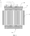
- FIG. 2 is a side view of a structure of a stator of a flat wire motor according to an embodiment of this application.
- the stator includes a stator core 10 and a stator winding 20.
- FIG. 3 is a top view of a structure of a stator core according to an embodiment of this application.
- an inner wall of the stator core 10 is provided with a plurality of winding slots 11.
- a quantity of the winding slots 11 may be represented by M, where M may be a natural number that is a multiple of 3, and may specifically be 54.
- M winding slots 11 are disposed on the inner wall of the stator core 10, and are uniformly disposed in a circumferential direction of the inner wall of the stator core 10. Any one of the winding slots 11 extends in an axial direction (a Z direction shown in FIG. 1 and FIG.
- stator core 10 has a wire-inlet end 10a and a wire-outlet end 10b in the axial direction of the stator core 10, and any one of the winding slots 11 may extend from the wire-inlet end 10a to the wire-outlet end 10b.
- the stator winding 20 includes flat wire conductors 21 inserted in the winding slots 11, and cross sections of the flat wire conductors 21 may be rectangular.
- the flat wire conductors 21 may be formed by hairpin coils.
- FIG. 4 is a schematic diagram of a structure of a hairpin coil according to an embodiment of this application.
- the hairpin coil 22 includes a leg 221 disposed in a winding slot 11, and a connected part 222 and a bent part 223 that are disposed outside the winding slot 11.
- the connected part 222 may be U-shaped or V-shaped. Refer to FIG. 1 and FIG. 4 .
- the hairpin coil 22 may be bent to form the bent part 223.
- the leg 221, inserted in the winding slot 11, of the hairpin coil 22 forms the flat wire conductor 21.
- head twisting directions of the bent part 223 of the hairpin coil 22 are consistent.
- the connected part 222 forms the plug-wire end 20a of the stator winding 20
- the bent part 223 forms the welding end 20b of the stator winding 20.
- FIG. 5 is a top view of a structure of a flat wire conductor that is inserted in a winding slot according to an embodiment of this application.
- N layers of flat wire conductors 21 may be disposed in any winding slot 11, where N may be 6 or 10.
- N is 6. That is, six layers of flat wire conductors are disposed in each winding slot 11. It may be understood that a quantity of layers of the flat wire conductors 21 shown in FIG. 5 is only described as an example. Six or ten layers of flat wire conductors 21 may be disposed.
- the flat wire conductors 21 inserted in the winding slots 11 are grouped and connected to form three phase windings.
- the three phase windings are a first-phase winding, a second-phase winding, and a third-phase winding, and respectively correspond to a U-phase winding, a V-phase winding, and a W-phase winding. Any one of the three phase windings may include a plurality of phase units.
- phase units of the first-phase winding, phase units of the second-phase winding, and phase units of the third-phase winding are sequentially and periodically arranged along the inner wall of the stator core.
- FIG. 6 is a distribution diagram of phase belts of a stator winding according to an embodiment of this application.
- three winding slots 11 that are adjacently disposed form one phase unit, and in one phase unit, all flat wire conductors 21 are in-phase.
- the U-phase winding, the V-phase winding, and the W-phase winding are alternately disposed based on phase units.
- the flat wire conductors 21 in a same winding slot 11 are in-phase. In this case, interphase insulating paper is not needed for the flat wire conductors 21 of different layers in the same winding slots 11, so that insulation costs of a motor may be reduced.
- FIG. 7 is a schematic diagram of a connection mode of flat wire conductors for forming a parallel branch according to an embodiment of this application.
- each phase winding may include two parallel branches. Any one of the parallel branches may connect flat wire conductors 21 of M ⁇ N/3P layers, and any one of the flat wire conductors 21 in the any one of the parallel branches is connected to an in-phase flat wire conductor 21 of an adjacent layer or a same layer in a winding slot 11 at an adjacent span.
- FIG. 8 is a schematic diagram of a circuit connection of three phase windings according to an embodiment of this application. As shown in FIG. 8 , in this embodiment of this application, the three phase windings of a stator winding each include two parallel circuits.
- a span of any parallel branch in a first layer is 9, and a combination of spans in an N th layer is 10, 10, and 7, or 8, 8, and 11.
- a combination of spans of any one of the parallel branches in the first layer is 10, 10, and 7, or 8, 8, and 11, and a span in the N th layer is 9.
- a span of any parallel branch from a second layer to an (N-1) th layer is 9.
- a wire-out end of any one of the parallel branches leads out from a flat wire conductor of the first layer or a flat wire conductor of the N th layer.
- a wire-in end and a wire-out end of a parallel branch can conveniently lead out.
- each phase winding includes a first parallel branch and a second parallel branch.
- a wire-in end of the first parallel branch is connected to a flat wire conductor of an (n1) th layer in an (m1) th winding slot
- a wire-out end of the first parallel branch is connected to a flat wire conductor of an (n2) th layer in an (m2) th winding slot.
- a difference between m1 and m2 is equal to a span.
- An absolute value of a difference between n1 and n2 is less than or equal to 1.
- An wire-in end of the second parallel branch is connected to a flat wire conductor of an (n1+2) th layer in the (m1) th winding slot, and a wire-out end of the second parallel branch is connected to a flat wire conductor of an (n2+2) th layer in the (m2) th winding slot, where m1 and m2 are natural numbers from 1 to M in a same phase winding, and n1 and n2 are natural numbers from 2 to N-2 in a same parallel branch.
- positions of wire-in ends and wire-out ends of different parallel branches of a same phase winding are close to each other, so that the wire-in ends and the wire-out ends may lead out from flat wire conductors of different layers in a same winding slot, to facilitate connection.
- An embodiment of this application further provides a flat wire motor.
- the flat wire motor includes a rotor and the stator according to embodiments of this application.
- the rotor is disposed in a space enclosed by an inner wall of the stator core.
- An embodiment of this application further provides a powertrain.
- the powertrain includes a reducer and the foregoing flat wire motor.
- the flat wire motor is in transmission connection with the reducer.
- a drive shaft of the flat wire motor may be in transmission connection with an input shaft of the reducer through a transmission part, for example, a coupling, to output a driving force from the flat wire motor to the reducer.
- An embodiment of this application provides a vehicle.
- the vehicle includes the foregoing powertrain.
- the powertrain is disposed in the vehicle and provides running power for the vehicle.
- the vehicle may be a new energy vehicle driven by electric energy.
- the new energy vehicle may be specifically a hybrid electric vehicle, a battery electric vehicle, a fuel cell electric vehicle, or the like, or may be a vehicle using an efficient accumulator, for example, a supercapacitor, a flywheel battery, or a flywheel accumulator as a source of electric energy.
- connection mode of a specific parallel branch in embodiments of this application with reference to specific embodiments.
- This embodiment provides a stator of a flat wire motor.
- the stator includes a stator core and a stator winding.
- the stator core has 54 winding slots, and a quantity of layers of conductors in each winding slot is 6.
- the stator winding includes a U-phase winding, a V-phase winding, and a W-phase winding.
- Each phase winding has two parallel branches.
- FIG. 9 is a schematic diagram of a connection of a first parallel branch of the U-phase winding in this embodiment.
- FIG. 10 is a schematic diagram of a connection of a second parallel branch of the U-phase winding in this embodiment.
- wire-in ends and wire-out ends of the first parallel branch and the second parallel branch of each phase winding are connected to a flat wire conductor of a first layer.
- each winding slot has flat wire conductors of six layers.
- the first layer is denoted as L1
- a second layer is denoted as L2
- a third layer is denoted as L3
- a fourth layer is denoted as L4
- a fifth layer is denoted as L5
- a sixth layer is denoted as L6.
- the first layer is a bottom layer of the winding slot
- the sixth layer is a top layer of the winding slot.
- "+” represents a current flowing into a conductor
- "-" represents a current flowing out of a conductor.
- a solid line represents a wiring mode of a plug-wire end
- a dotted line represents a wiring mode of a welding end
- the following describes in detail a wiring mode of the first parallel branch of the U-phase winding in this embodiment with reference to FIG. 9 .
- the following describes a wiring mode of the stator winding at the welding end only based on the connection mode represented by the dotted line in FIG. 9 .
- a connecting wire at the plug-wire end of the stator winding may be directly connected through a connected part of a hairpin coil.
- the connection mode represented by the solid line in FIG. 9 refer to the connection mode represented by the solid line in FIG. 9 .
- a first layer in a 48 th slot is used as a wire-in end V 1in .
- the first parallel branch enters from the first layer in the 48 th slot and leads out from a second layer in a third slot, then enters from a first layer in a 12 th slot and leads out from a second layer in a 21 st slot, then enters from a third layer in a 30 th slot and leads out from a fourth layer in a 39 th slot, then enters from a fifth layer in the 48 th slot and leads out from a sixth layer in the third slot, and then enters from a fifth layer in the 12 th slot and leads out from a sixth layer in the 21 st slot.
- the first parallel branch may traverse from a first layer to a sixth layer, and may be circumferentially disposed around the stator core for one circle.
- the first parallel branch performs a next traversal according to the foregoing method.
- the first parallel branch enters from a sixth layer in a 28 th slot and leads out from a fifth layer in a 19 th slot, then enters a fourth layer in a 10 th slot and leads out from a third layer in a first slot, then enters a fourth layer in a 46 th slot and leads out from a third layer in a 37 th slot, and then enters from a second layer in the 28 th slot and leads out from a first layer in the 19 th slot, and in this case, the first parallel branch completes a second traversal.
- the first parallel branch enters from a first layer in the 10 th slot and leads out from a second layer in the 19 th slot, then enters from a first layer in the 28 th slot and leads out from a second layer in the 37 th slot, then enters from a third layer in the 46 th slot and leads out from a fourth layer in the first slot, then enters from a fifth layer in the 10 th slot and leads out from a sixth layer in the 19 th slot, and then enters from a fifth layer in the 28 th slot and leads out from a sixth layer in the 37 th slot, and in this case, the first parallel branch completes a third traversal.
- the first parallel branch enters from a sixth layer in a 47 th slot and leads out from a fifth layer in a 38 th slot, then enters from a fourth layer in a 29 th slot and leads out from a third layer in a 20 th slot, then enters from a fourth layer in an 11 th slot and leads out from a third layer in a second slot, and then enters from a second layer in the 47 th slot and leads out from a first layer in the 38 th slot, and in this case, the first parallel branch completes a fourth traversal.
- the first parallel branch enters from a first layer in the 29 th slot and leads out from a second layer in the 38 th slot, then enters from a first layer in the 47 th slot and leads out from a second layer in the second slot, then enters from a third layer in the 11 th slot and leads out from a fourth layer in the 20 th slot, then enters from a fifth layer in the 29 th slot and leads out from a sixth layer in the 38 th slot, and then enters from a fifth layer in the 47 th slot and leads out from a sixth layer in the second slot, and in this case, the first parallel branch completes a fifth traversal.
- the first parallel branch enters from a sixth layer in the 12 th slot and leads out from a fifth layer in the third slot, then enters from a fourth layer in the 48 th slot and leads out from a third layer in the 39 th slot, then enters from a fourth layer in the 30 th slot and leads out from a third layer in the 21 st slot, and then enters from a second layer in the 12 th slot and leads out from a first layer in the third slot, and in this case, the first parallel branch leads out from the first layer in the third slot, to form a wire-out end U 1out of the first parallel branch of the U-phase winding.
- the first parallel branch enters from the first layer in the 48 th slot and leads out from the second layer in the third slot means that at the welding end, the flat wire conductor of the first layer in the 48 th slot is connected to the flat wire conductor of the second layer in the third slot.
- the following describes in detail a wiring mode of the second parallel branch of the U-phase winding in this embodiment with reference to FIG. 10 .
- the following describes a wiring mode of the stator winding at the welding end only based on the connection mode represented by the dotted line in FIG. 10 .
- a connecting wire at the plug-wire end of the stator winding may be directly connected through a connected part of a hairpin coil.
- the connection mode represented by the solid line in FIG. 10 refer to the connection mode represented by the solid line in FIG. 10 .
- a first layer in the 30 th slot is used as a wire-in end V 2in .
- the second parallel branch enters from the first layer in the 30 th slot and leads out from a second layer in the 39 th slot, then enters from a third layer in the 48 th slot and leads out from a fourth layer in the third slot, then enters from a third layer in the 12 th slot and leads out from a fourth layer in the 21 st slot, and then enters from a fifth layer in the 30 th slot and leads out from a sixth layer in the 39 th slot, and in this case, the second parallel branch completes a first traversal.
- the second parallel branch enters from a sixth layer in the 29 th slot and leads out from a fifth layer in the 20 th slot, then enters from a sixth layer in the 11 th slot and leads out from a fifth layer in the second slot, then enters from a fourth layer in the 47 th slot and leads out from a third layer in the 38 th slot, then enters from a second layer in the 29 th slot and leads out from a first layer in the 20 th slot, and then enters from a second layer in the 11 th slot and leads out from a first layer in the second slot, and in this case, the second parallel branch completes a second traversal.
- the second parallel branch enters from a first layer in the 11 th slot and leads out from a second layer in the 20 th slot, then enters from a third layer in the 29 th slot and leads out from a fourth layer in the 38 th slot, then enters from a third layer in the 47 th slot and leads out from a fourth layer in the second slot, and then enters from a fifth layer in the 11 th slot and leads out from a sixth layer in the 20 th slot, and in this case, the second parallel branch completes a third traversal.
- the second parallel branch enters from a sixth layer in the 10 th slot and leads out from a fifth layer in the first slot, then enters from a sixth layer in the 46 th slot and leads out from a fifth layer in the 37 th slot, then enters from a fourth layer in the 28 th slot and leads out from a third layer in the 19 th slot, then enters from a second layer in the 10 th slot and leads out from a first layer in the first slot, and then enters from a second layer in the 46 th slot and leads out from a first layer in the 37 th slot, and in this case, the second parallel branch completes a fourth traversal.
- the second parallel branch enters from a first layer in the 46 th slot and leads out from a second layer in the first slot, then enters from a third layer in the 10 th slot and leads out from a fourth layer in the 19 th slot, then enters from a third layer in the 28 th slot and leads out from a fourth layer in the 37 th slot, and then enters from a fifth layer in the 46 th slot and leads out from a sixth layer in the first slot, and in this case, the second parallel branch completes a fifth traversal.
- the second parallel branch enters from a sixth layer in the 47 th slot and leads out from a fifth layer in the 39 th slot, then enters from a sixth layer in the 30 th slot and leads out from a fifth layer in the 21 st slot, then enters from a fourth layer in the 12 th slot and leads out from a third layer in the third slot, then enters from a second layer in the 48 th slot and leads out from a first layer in the 39 th slot, and then enters from a second layer in the 30 th slot and leads out from a first layer in the 21 st layer.
- the second parallel branch leads out from the first layer in the 21 st layer, to form a wire-out end U 2out in the second parallel branch of the U-phase winding.
- a combination of spans in the first layer in the first parallel branch is 9 and 9
- a combination of spans in the sixth layer is 10, 10, and 7
- each of spans between every adjacent two layers from the second layer to the fifth layer is 9.
- Ulin, Ulout, U2in, and U2out each lead out from the plug-wire end of the stator winding, that is, lead out from a side of the connected part of the hairpin coil.
- a connected part between U1in and U1out is disconnected, and U1in and U1out separately lead out by using a conducting wire.
- a connected part between U2in and U2out is disconnected, and U2in and U2out separately lead out by using a conducting wire.
- spans of most flat wire conductors are the same. Therefore, when the stator winding is wound, hairpin coils of a same model may be used, so that a quantity of models of hairpin coils is reduced and automatic insertion is facilitated.
- spans of parallel branches are the same at the welding end, to facilitate connection.
- a wiring mode of a first parallel branch of the V-phase winding and a wiring mode of a first parallel branch of the W-phase winding may be obtained through translation on the basis of FIG. 9 .
- a wiring mode of a second parallel branch of the V-phase winding and a wiring mode of a second parallel branch of the W-phase winding may be obtained through translation on the basis of FIG. 10 .
- a wire-in end and a wire-out end of each of a first parallel branch and a second parallel branch of each phase winding are located on a first layer.
- the three phase windings may directly lead out in parallel, or may be connected by using busbars to lead out.
- Neutral points may be welded directly or connected together by using busbars.
- each parallel branch traverses phase belts and flat wire conductor layers that can be arranged, so that each parallel branch can maintain a potential balance, and no cross current is generated. It can be learned from FIG. 6 , FIG. 9 , and FIG. 10 , conductors in a same slot are in-phase. In this case, insulating paper is not needed between flat wire conductors, to reduce insulation costs.
- FIG. 11 is a schematic diagram of a connection of a first parallel branch of a U-phase winding in this embodiment.
- FIG. 12 is a schematic diagram of a connection of a second parallel branch of a U-phase winding in this embodiment.
- a wire-in end U1in of the first parallel branch is a first layer in a 28 th slot
- a wire-out end U 1out of the first parallel branch is a second layer in a 19 th slot.
- the original flat wire conductor of the first layer in the 48 th slot and the original flat wire conductor of the first layer in the third slot are connected to the plug-wire end of the stator winding, a connected part between the flat wire conductor of the first layer in the 28 th slot and the flat wire conductor of the second layer in the 19 th slot is disconnected at the plug-wire end of the stator winding, and then, the flat wire conductor of the first layer in the 28 th slot and the flat wire conductor of the second layer in the 19 th slot separately lead out by using a leading wire.
- a wiring mode of a flat wire conductor in another position may not be changed. In this connection mode, a combination of spans in the first layer is 9, 9, and 9, and a combination of spans in the sixth layer is 10, 10, and 7.
- the wire-in end U2in of the second parallel branch is a third layer in the 28 th slot
- the wire-out end U2out is a fourth layer in the 19 th slot.
- the original flat wire conductor of the first layer in the 30 th slot and the flat wire conductor of the first layer in the 21 st slot are connected at the plug-wire end of the stator winding
- the connected part between a flat wire conductor of the third layer in the 28 th slot and a flat wire conductor of the fourth layer in the 19 th slot is disconnected at the plug-wire end of the stator winding
- the flat wire conductor of the third layer in the 28 th slot and the flat wire conductor of the fourth layer in the 19 th slot separately lead out by using a leading wire.
- a wiring mode of a flat wire conductor in another position may not be changed.
- FIG. 13 is a schematic diagram of a connection of a first parallel branch of a U-phase winding in this embodiment.
- FIG. 14 is a schematic diagram of a connection of a second parallel branch of a U-phase winding in this embodiment.
- both the wire-in end and the wire-out end of each parallel branch are disposed at a welding end of a stator winding.
- a wire-in end U1in of the first parallel branch is a second layer in a second slot
- a wire-out end U 1out is a first layer in a 47 th slot.
- the original flat wire conductor of the first layer in the 48 th slot and the original flat wire conductor of the first layer in the third slot are connected at the plug-wire end of the stator winding, the bent part between the flat wire conductor of the second layer in the second slot and the flat wire conductor of the first layer in the 47 th slot is disconnected at the welding end of the stator winding, and then, the flat wire conductor of the second layer in the second slot and the flat wire conductor of the first layer in the 47 th slot separately lead out by using a leading wire.
- a wiring mode of a flat wire conductor in another position may not be changed.
- the wire-in end U2in of the second parallel branch is a fourth layer in the second slot
- the wire-out end U2out is a third layer in the 47 th slot.
- the original flat wire conductor of the first layer in the 30 th slot and the flat wire conductor of the first layer in the 21 st slot are connected at the plug-wire end of the stator winding, the connected part between the flat wire conductor of the fourth layer in the second slot and the flat wire conductor of the third layer in the 47 th slot is disconnected at the plug-wire end of the stator winding, and then, the flat wire conductor of the fourth layer in the second slot and the flat wire conductor of the third layer in the 47 th slot separately lead out by using a leading wire.
- a wiring mode of a flat wire conductor in another position may not be changed.
- Embodiment 3 Compared with Embodiment 1, the wire-in end and the wire-out end of each parallel branch in Embodiment 3 are switched from the plug-wire end of the stator winding to the welding end of the stator winding.
- the switching form is simple and easy, and positions of the wire-in end and the wire-out end may be flexibly selected.
- Embodiment 3 by using this wiring mode, wire-in ends of two parallel branches are located in a same winding slot, wire-out ends are located in a same winding slot. Therefore, a connection distance may be smaller.
- FIG. 15 is a schematic diagram of a connection of two parallel branches of the U-phase winding in this embodiment.
- FIG. 16 is a schematic diagram of a connection of the U-phase winding, a V-phase winding, and a W-phase winding in this embodiment.
- wire-in ends and wire-out ends of six parallel branches of the three phase windings are close to each other, and may directly lead out in parallel, or may lead out after being connected together by using a busbar. Therefore, lead-out distances of the wire-in ends and the wire-out ends are short, and the wire-in ends and the wire-out ends may lead out from the welding end.
- FIG. 17 is a schematic diagram of a connection of a first parallel branch of a U-phase winding in this embodiment.
- FIG. 18 is a schematic diagram of a connection of a second parallel branch of a U-phase winding in this embodiment.
- positions of a wire-in end and a wire-out end of each of the first parallel branch and the second parallel branch of each phase are the same as those in Embodiment 1, and a difference lies in that a span of each parallel branch in a first layer and a sixth layer is changed.
- a combination of spans in the first layer is 9 and 9, and a combination of spans in the sixth layer is 10, 10, and 7.
- the combination of spans of the first layer is 9 and 9, and the combination of spans in the sixth layer is 8, 8, and 11.
- FIG. 17 shows only a wiring mode of the first parallel branch at the first layer and the sixth layer.
- FIG. 9 For wiring modes of the remaining intermediate layers from the second layer to the fifth layer, refer to FIG. 9 in Embodiment 1.
- FIG. 18 shows only a wiring mode of the second parallel branch at the first layer and the sixth layer.
- FIG. 10 For wiring modes of the remaining intermediate layers from the second layer to the fifth layer, refer to FIG. 10 in Embodiment 1.
- This embodiment provides a stator.
- a stator core has 54 winding slots, and a quantity of layers of conductors in each winding slot is 10.
- the stator winding includes a U-phase winding, a V-phase winding, and a W-phase winding.
- Each phase winding has two parallel branches.
- FIG. 19 is a distribution diagram of phase belts of a stator winding in an embodiment.
- FIG. 20 is a schematic diagram of a connection of a first parallel branch of a U-phase winding in an embodiment.
- FIG. 21 is a schematic diagram of a connection of a second parallel branch of a U-phase winding in an embodiment.
- each winding slot has flat wire conductors of 10 layers.
- a first layer is denoted as L1
- a second layer is denoted as L2
- a third layer is denoted as L3
- a fourth layer is denoted as L4
- a fifth layer is denoted as L5
- a sixth layer is denoted as L6
- a seventh layer is denoted as L7
- an eighth layer is denoted as L8
- a ninth layer is denoted as L9
- a 10 th layer is denoted as L10.
- the first layer is a bottom layer of the winding slot
- the 10 th layer is a top layer of the winding slot.
- a solid line represents a wiring mode of a plug-wire end
- a dotted line represents a wiring mode of a welding end
- the following describes in detail a wiring mode of the first parallel branch of the U-phase winding in this embodiment with reference to FIG. 20 .
- the following describes a wiring mode of the stator winding at the welding end only according to the connection mode represented by the dotted line in FIG. 20 .
- a connecting wire at the plug-wire end of the stator winding may be directly connected through a connected part of a hairpin coil.
- the connection mode represented by the solid line in FIG. 20 refer to the connection mode represented by the solid line in FIG. 20 .
- a second layer in a first slot is used as a wire-in end U 1in .
- the second layer in the first slot is not connected, at the welding end of the stator winding, to a flat wire conductor of another layer.
- the first parallel branch enters from a third layer in a 10 th slot and leads out from a fourth layer in a 19 th slot, then enters from a fifth layer in a 28 th slot and leads out from a sixth layer in a 37 th slot, then enters from a fifth layer in a 46 th slot and leads out from a sixth layer in the first slot, then enters from a seventh layer in the 10 th slot and leads out from an eighth layer in the 19 th slot, and then enters from a ninth layer in the 28 th slot and leads out from a 10 th layer in the 37 th slot.
- the first parallel branch traverses from a first layer to a sixth layer, and may be circumferentially disposed around the stator core for at least one circle.
- the first parallel branch performs a next traversal according to the foregoing method. Specifically, the first parallel branch enters a 10 th layer in a 47 th slot and leads out from a ninth layer in a 38 th slot, then enters a 10 th layer in a 29 th slot and leads out from an eighth layer in a 20 th slot, then enters from an eighth layer in an 11 th slot and leads out from a seventh layer in a second slot, then enters from an eighth layer in the 47 th slot and leads out from a seventh layer in the 38 th slot, then enters from a sixth layer in the 29 th slot and leads out from a fifth layer in the 20 th slot, then enters from a fourth layer in the 11 th slot and leads out from a third layer in the second slot, then enters a fourth layer in the 47 th slot and leads out from a third layer in the 38 th slot, and then enters from a second layer in the 29 th slot and leads out from a first layer in the 20
- the first parallel branch enters from a first layer in the 11 th slot and leads out from a second layer in the 20 th slot, then enters from a first layer in the 29 th slot and leads out from a second layer in the 38 th slot, then enters from a third layer in the 47 th slot and leads out from a fourth layer in the second slot, then enters from a fifth layer in the 11 th slot and leads out from a sixth layer in the 20 th slot, then enters from a fifth layer in the 29 th slot and leads out from a sixth layer in the 38 th slot, then enters from a seventh layer in the 47 th slot and leads out from an eighth layer in the second slot, and then enters from a ninth layer in the 11 th slot and leads out from a 10 th layer in the 20 th slot, and in this case, the first parallel branch completes a third traversal.
- the first parallel branch enters from a 10 th layer in a 30 th slot and leads out from a ninth layer in a 21 st slot, then enters from a 10 th layer in a 12 th slot and leads out from a ninth layer in a third slot, then enters from an eighth layer in a 48 th slot and leads out from a seventh layer in a 39 th slot, then enters from an eighth layer in the 30 th slot and leads out from a seventh layer in the 21 st slot, then enters from a sixth layer in the 12 th slot and leads out from a fifth layer in the third slot, then enters from a fourth layer in the 48 th slot and leads out from a third layer in the 39 th slot, then enters form a fourth layer in the 30 th slot and leads out from a third layer in the 21 st slot, and then enters from a second layer in the 12 th slot and leads out from a first layer in the third slot, and in this case, the first parallel branch completes
- the first parallel branch enters from a first layer in the 48 th slot and leads out from a second layer in the third slot, then enters from a first layer in the 12 th slot and leads out from a second layer in the 21 st slot, then enters from a third layer in the 30 th slot and leads out from a fourth layer in the 39 th slot, then enters from a fifth layer in the 48 th slot and leads out from a sixth layer in the third slot, then enters from a fifth layer in the 12 th slot and leads out from a sixth layer in the 21 st slot, then enters from a seventh layer in the 30 th slot and leads out from an eighth layer in the 39 th slot, and then enters from a ninth layer in the 48 th slot and leads out from a 10 th layer in the third slot, and in this case, the first parallel branch completes a fifth traversal.
- the first parallel branch enters from a 10 th layer in the 10 th slot and leads out from a ninth layer in the first slot, then enters from a 10 th layer in the 46 th slot and leads out from a ninth layer in the 37 th slot, then enters from an eighth layer in the 28 th slot and leads out from a seventh layer in the 19 th slot, then enters from an eighth layer in the 10 th slot and leads out from a seventh layer in the first slot, then enters from a sixth layer in the 46 th slot and leads out from a fifth layer in the 37 th slot, then enters from a fourth layer in the 28 th slot and leads out from a third layer in the 19 th slot, then enters from a fourth layer in the 10 th slot and leads out from a third layer in the first slot, then enters from a second layer in the 46 th slot and leads out from a first layer in the 37 th slot, then enters from a first layer in the 28 th slot and leads out from a second
- the following describes in detail a wiring mode of the second parallel branch of the U-phase winding in this embodiment with reference to FIG. 21 .
- the following describes a wiring mode of the stator winding at the welding end only based on the connection mode represented by the dotted line in FIG. 21 .
- a connecting wire at the plug-wire end of the stator winding may be directly connected through a connected part of a hairpin coil.
- the connection mode represented by the solid line in FIG. 21 refer to the connection mode represented by the solid line in FIG. 21 .
- a fourth layer in a first slot is used as a wire-in end U 2in .
- the fourth layer in the first slot is not connected, at the plug-wire end of the stator winding, to a flat wire conductor of another layer.
- the second parallel branch enters from a fifth layer in a 10 th slot and leads out from a sixth layer in a 19 th slot, then enters from a seventh layer in a 28 th slot and leads out from an eighth layer in a 37 th slot, then enters from a seventh layer in a 46 th slot and leads out from an eighth layer in a first slot, then enters from a ninth layer in the 10 th slot and leads out from a 10 th layer in the 19 th slot, and then enters from a ninth layer in the 28 th slot and leads out from a 10 th layer in the 37 th slot, and in this case, the second parallel branch completes a first traversal.
- the second parallel branch enters from a 10 th layer in a 30 th slot and leads out from a ninth layer in a 21 st slot, then enters from an eighth layer in a 12 th slot and leads out from a seventh layer in a third slot, then enters from a sixth layer in a 48 th slot and leads out from a fifth layer in a 39 th slot, then enters from a sixth layer in the 30 th slot and leads out from a fifth layer in the 21 st slot, then enters from a fourth layer in the 12 th slot and leads out from a third layer in the third slot, then enters from a second layer in the 48 th slot and leads out from a first layer in the 39 th slot, and then enters from a second layer in the 30 th slot and leads out from a first layer in the 21 st slot, and in this case, the second parallel branch completes a second traversal.
- the second parallel branch enters from a first layer in the 30 th slot and leads out from a second layer in the 39 th slot, then enters from a third layer in the 48 th slot and leads out from a fourth layer in the third slot, then enters from a third layer in the 12 th slot and leads out from a fourth layer in the 21 st slot, then enters from a fifth layer in the 30 th slot and leads out from a sixth layer in the 39 th slot, then enters from a seventh layer in the 48 th slot and leads out from an eighth layer in the third slot, then enters from a seventh layer in the 12 th slot and leads out from an eighth layer in the 21 st slot, then enters form a ninth layer in the 30 th slot and leads out from a 10 th layer in the 39 th slot, and then enters from a ninth layer in the 48 th slot and leads out from a 10 th layer in the third slot, and in this case, the second parallel branch completes a third traversal.
- the second parallel branch enters from a 10 th layer in a 47 th slot and leads out from a ninth layer in a 38 th slot, then enters from an eighth layer in a 29 th slot and leads out from a seventh layer in a 20 th slot, then enters from a sixth layer in an 11 th slot and leads out from a fifth layer in a second slot, then enters from a sixth layer in the 47 th slot and leads out from a fifth layer in the 38 th slot, then enters from a fourth layer in the 29 th slot and leads out from a third layer in the 20 th slot, then enters from a second layer in the 11 th slot and leads out from a first layer in the second slot, and then enters from a second layer in the 47 th slot and leads out from a first layer in the 38 th slot, and in this case, the second parallel branch completes a fourth traversal.
- the second parallel branch enters a first layer in the 47 th slot and leads out from a second layer in a second slot, then enters a third layer in the 11 th slot and leads out from a fourth layer in the 20 th slot, then enters from a third layer in the 29 th slot and leads out from a fourth layer in the 38 th slot, then enters from a fifth layer in the 47 th slot and leads out from a sixth layer in the second slot, then enters from a seventh layer in the 11 th slot and leads out from an eighth layer in the 20 th slot, then enters from a seventh layer in the 29 th slot and leads out from an eighth layer in the 38 th slot, then enters a ninth layer in the 47 th slot and leads out from a 10 th layer in the second slot, and then enters from a ninth layer in the 11 th slot and leads out from a 10 th layer in the 20 th slot, and in this case, the second parallel branch completes a fifth traversal.
- the second parallel branch enters from a 10 th layer in the 10 th slot and leads out from a ninth layer in the first slot, then enters from an eighth layer in the 46 th slot and leads out from a seventh layer in the 37 th slot, then enters from a sixth layer in the 28 th slot and leads out from a fifth layer in the 19 th slot, then enters from a sixth layer in the 10 th slot and leads out from a fifth layer in the first slot, then enters from a fourth layer in the 46 th slot and leads out from a third layer in the 37 th slot, then enters from a second layer in the 28 th slot and leads out from a first layer in the 19 th slot, then enters from a second layer in the 10 th slot and leads out from a first layer in the first slot, then enters from a first layer in the 10 th slot and leads out from a second layer in the 19 th slot, then enters from a third layer in the 28 th slot and leads out from a fourth layer
- a combination of spans in the first layer of the first parallel branch is 9, 9, and 9
- a combination of spans in the 10 th layer is 10, 7, and 10
- each of spans between every adjacent two layers from the second layer to the ninth layer is 9.
- Ulin, Ulout, U2in, and U2out each lead out from the welding end of the stator winding, that is, lead out from a side of the bent part of the hairpin coil.
- U1in and U1out separately lead out by using a conducting wire
- U2in and U2out separately lead out by using a conducting wire.
- spans of most flat wire conductors are the same.
- hairpin coils of a same model may be used, so that a quantity of models of hairpin coils is reduced and automatic insertion is facilitated.
- spans of parallel branches are the same at the welding end, to facilitate connection.
- a wiring mode of a first parallel branch of the V-phase winding and a wiring mode of a first parallel branch of the W-phase winding may be obtained through translation on the basis of FIG. 20 .
- a wiring mode of a second parallel branch of the V-phase winding and a wiring mode of a second parallel branch of the W-phase winding may be obtained through translation on the basis of FIG. 21 .
- stator in embodiments of this application has the following advantages.
Landscapes
- Engineering & Computer Science (AREA)
- Power Engineering (AREA)
- Windings For Motors And Generators (AREA)
- Reciprocating, Oscillating Or Vibrating Motors (AREA)
Applications Claiming Priority (1)
| Application Number | Priority Date | Filing Date | Title |
|---|---|---|---|
| CN202111277405.6A CN114204708B (zh) | 2021-10-30 | 2021-10-30 | 定子、扁线电机、动力总成和车辆 |
Publications (1)
| Publication Number | Publication Date |
|---|---|
| EP4175125A1 true EP4175125A1 (de) | 2023-05-03 |
Family
ID=80646540
Family Applications (1)
| Application Number | Title | Priority Date | Filing Date |
|---|---|---|---|
| EP22195900.0A Pending EP4175125A1 (de) | 2021-10-30 | 2022-09-15 | Stator, flachdrahtmotor, antriebsstrang und fahrzeug |
Country Status (5)
| Country | Link |
|---|---|
| US (1) | US12301082B2 (de) |
| EP (1) | EP4175125A1 (de) |
| CN (1) | CN114204708B (de) |
| TW (1) | TWI815630B (de) |
| WO (1) | WO2023071456A1 (de) |
Families Citing this family (23)
| Publication number | Priority date | Publication date | Assignee | Title |
|---|---|---|---|---|
| CN114204708B (zh) | 2021-10-30 | 2023-04-07 | 华为数字能源技术有限公司 | 定子、扁线电机、动力总成和车辆 |
| CN114744785B (zh) * | 2022-04-21 | 2025-09-19 | 上海易唯科电机技术有限公司 | 一种槽内导线数量为偶数的不等宽槽定子组件及电机 |
| WO2024007713A1 (zh) * | 2022-07-06 | 2024-01-11 | 浙江凌昇动力科技有限公司 | 定子、扁线电机、动力总成和车辆 |
| CN115189498B (zh) * | 2022-07-07 | 2024-05-03 | 一汽解放汽车有限公司 | 一种扁线电机的定子、扁线电机及车辆 |
| WO2024021885A1 (zh) * | 2022-07-26 | 2024-02-01 | 安徽威灵汽车部件有限公司 | 定子组件、电机和车辆 |
| CN115395697B (zh) * | 2022-08-24 | 2025-11-04 | 株洲中车时代电气股份有限公司 | 一种扁线绕组、具有其的定子、电机和车辆 |
| CN117791921B (zh) * | 2022-09-09 | 2026-04-28 | 上海汽车电驱动有限公司 | 三相对称绕组排布驱动电机及车辆 |
| EP4580002A4 (de) * | 2022-09-23 | 2025-10-22 | Contemporary Amperex Intelligence Tech Shanghai Limited | Elektrische vorrichtung sowie motor und stator dafür |
| CN115765233B (zh) * | 2022-11-28 | 2026-02-03 | 浙江极氪智能科技有限公司 | 一种定子组件及电机 |
| CN115940446B (zh) * | 2022-11-28 | 2025-11-21 | 浙江极氪智能科技有限公司 | 定子组件及电机 |
| CN115986970B (zh) * | 2022-11-28 | 2026-04-03 | 浙江极氪智能科技有限公司 | 定子组件及电机 |
| CN115733281B (zh) * | 2022-11-28 | 2026-04-24 | 浙江极氪智能科技有限公司 | 一种定子组件 |
| CN117277632A (zh) * | 2022-11-28 | 2023-12-22 | 浙江极氪智能科技有限公司 | 定子组件、驱动电机及定子组件的绕组绕线方法 |
| CN116094197B (zh) * | 2022-11-28 | 2025-11-21 | 浙江极氪智能科技有限公司 | 定子组件及电机 |
| CN118381223A (zh) * | 2023-01-20 | 2024-07-23 | 华为数字能源技术有限公司 | 电机、动力总成和车辆 |
| CN115986991B (zh) * | 2023-02-15 | 2026-02-17 | 天蔚蓝电驱动科技(江苏)有限公司 | 扁线电机的定子和扁线电机 |
| CN115940466B (zh) * | 2023-02-09 | 2023-06-27 | 天蔚蓝电驱动科技(江苏)有限公司 | 扁线电机的定子 |
| CN115940471B (zh) * | 2023-03-10 | 2023-05-26 | 博格华纳汽车零部件(武汉)有限公司 | 一种连续波绕电枢绕组及电机 |
| CN116191736A (zh) * | 2023-03-29 | 2023-05-30 | 中国第一汽车股份有限公司 | 扁线电机及具有其的车辆 |
| CN116054456B (zh) * | 2023-04-01 | 2023-06-02 | 博格华纳汽车零部件(武汉)有限公司 | 一种72槽8极连续波绕绕组及电机 |
| CN116404788B (zh) * | 2023-06-08 | 2023-08-11 | 博格华纳汽车零部件(武汉)有限公司 | 一种72槽6极发夹式扁线电枢绕组及电机 |
| CN119834495B (zh) * | 2025-01-07 | 2025-10-31 | 无锡星驱动力科技有限公司 | 一种扁线电机定子、扁线电机及车辆 |
| CN120150410A (zh) * | 2025-05-06 | 2025-06-13 | 格至驱智能科技(上海)有限公司 | 电枢绕组和电机 |
Citations (4)
| Publication number | Priority date | Publication date | Assignee | Title |
|---|---|---|---|---|
| US6995492B1 (en) * | 2002-07-12 | 2006-02-07 | Denso Corporation | Electric rotary machine equipped with stator coil consisting of sequentially connected conductor segments |
| US20060033394A1 (en) * | 2002-06-12 | 2006-02-16 | Denso Corporation | Sequentially joined-segment coil for rotary electrical machine |
| WO2019231002A1 (ko) * | 2018-05-29 | 2019-12-05 | 엘지전자 주식회사 | 3상 전동기의 권선 패턴 구조 |
| CN112531933A (zh) * | 2020-12-16 | 2021-03-19 | 天津市松正电动汽车技术股份有限公司 | 一种电机定子及电机 |
Family Cites Families (14)
| Publication number | Priority date | Publication date | Assignee | Title |
|---|---|---|---|---|
| JP2012222874A (ja) * | 2011-04-05 | 2012-11-12 | Denso Corp | 回転電機の固定子 |
| US9379586B2 (en) | 2013-04-24 | 2016-06-28 | GM Global Technology Operations LLC | Bar wound stator winding layout with long-pitched and short-pitched coils |
| CN109586456B (zh) * | 2017-09-29 | 2021-06-18 | 比亚迪股份有限公司 | 电机、定子组件及其线圈绕线方法 |
| CN110556954B (zh) * | 2018-05-31 | 2021-10-22 | 比亚迪股份有限公司 | 定子组件以及电机 |
| CN110011450B (zh) * | 2019-03-27 | 2024-08-02 | 汇川新能源汽车技术(常州)有限公司 | 定子组件及驱动电机 |
| CN110829641B (zh) * | 2019-10-29 | 2022-04-01 | 合肥巨一动力系统有限公司 | 发卡扁线电机定子及发卡扁线电机 |
| CN110971039A (zh) | 2019-12-18 | 2020-04-07 | 浙江龙芯电驱动科技有限公司 | 一种72槽8极扁铜线绕组结构以及应用该绕组结构的电机 |
| JP2021158849A (ja) * | 2020-03-27 | 2021-10-07 | 株式会社アイシン | 回転電機 |
| CN111355317B (zh) * | 2020-04-09 | 2021-08-27 | 合肥巨一动力系统有限公司 | 一种扁线定子及扁线电机 |
| CN212850004U (zh) * | 2020-07-15 | 2021-03-30 | 华为技术有限公司 | 定子组件、电机及电动汽车 |
| WO2022077498A1 (zh) * | 2020-10-16 | 2022-04-21 | 华为数字能源技术有限公司 | 扁线电机、动力总成及车辆 |
| CN112583168B (zh) | 2020-12-16 | 2025-02-25 | 博格华纳动力驱动系统(天津)有限公司 | 一种电机定子绕组、定子及电机 |
| CN113422453B (zh) * | 2021-05-14 | 2022-10-28 | 华为数字能源技术有限公司 | 一种六相扁线波绕组结构、六相电机、动力总成和车辆 |
| CN114204708B (zh) * | 2021-10-30 | 2023-04-07 | 华为数字能源技术有限公司 | 定子、扁线电机、动力总成和车辆 |
-
2021
- 2021-10-30 CN CN202111277405.6A patent/CN114204708B/zh active Active
-
2022
- 2022-08-19 WO PCT/CN2022/113682 patent/WO2023071456A1/zh not_active Ceased
- 2022-08-30 TW TW111132674A patent/TWI815630B/zh active
- 2022-09-14 US US17/944,424 patent/US12301082B2/en active Active
- 2022-09-15 EP EP22195900.0A patent/EP4175125A1/de active Pending
Patent Citations (4)
| Publication number | Priority date | Publication date | Assignee | Title |
|---|---|---|---|---|
| US20060033394A1 (en) * | 2002-06-12 | 2006-02-16 | Denso Corporation | Sequentially joined-segment coil for rotary electrical machine |
| US6995492B1 (en) * | 2002-07-12 | 2006-02-07 | Denso Corporation | Electric rotary machine equipped with stator coil consisting of sequentially connected conductor segments |
| WO2019231002A1 (ko) * | 2018-05-29 | 2019-12-05 | 엘지전자 주식회사 | 3상 전동기의 권선 패턴 구조 |
| CN112531933A (zh) * | 2020-12-16 | 2021-03-19 | 天津市松正电动汽车技术股份有限公司 | 一种电机定子及电机 |
Also Published As
| Publication number | Publication date |
|---|---|
| TW202312628A (zh) | 2023-03-16 |
| TWI815630B (zh) | 2023-09-11 |
| WO2023071456A1 (zh) | 2023-05-04 |
| US12301082B2 (en) | 2025-05-13 |
| US20230009407A1 (en) | 2023-01-12 |
| CN114204708B (zh) | 2023-04-07 |
| CN114204708A (zh) | 2022-03-18 |
Similar Documents
| Publication | Publication Date | Title |
|---|---|---|
| EP4175125A1 (de) | Stator, flachdrahtmotor, antriebsstrang und fahrzeug | |
| CN114583863B (zh) | 定子、扁线电机、动力总成和车辆 | |
| EP4135165A1 (de) | Motorstator, motor und fahrzeug | |
| US12261496B2 (en) | Six-phase flat wire wave winding structure, six-phase motor, powertrain, and vehicle | |
| CN218920099U (zh) | 定子、扁线电机、动力总成和车辆 | |
| US11575288B2 (en) | Hairpin winding electric machine | |
| CN115765254A (zh) | 定子、扁线电机、动力总成和车辆 | |
| US11309761B2 (en) | Hairpin winding electric machine | |
| CN218920101U (zh) | 车辆、动力总成、扁线电机及其定子 | |
| CN115498794A (zh) | 电机定子、扁线电机、动力总成和动力装置 | |
| WO2024007709A1 (zh) | 定子、扁线电机、动力总成及车辆 | |
| CN210608719U (zh) | 一种车用永磁同步电机扁线定子 | |
| EP4407844B1 (de) | Flachdraht-elektromotor und stator dafür | |
| JP3251626U (ja) | ステータ、フラットワイヤーモータ、パワートレーン及び車両 | |
| US12301083B2 (en) | Motor, and stator and electric device thereof | |
| EP4404437A1 (de) | Motor, antriebsstrang und fahrzeug | |
| CN218920102U (zh) | 定子、扁线电机、动力总成和车辆 | |
| CN218352272U (zh) | 定子组件、电机和车辆 | |
| CN221597535U (zh) | 定子、扁线电机及动力总成 | |
| WO2024021885A1 (zh) | 定子组件、电机和车辆 | |
| CN212435461U (zh) | 一种短节距电机定子 | |
| JP2025528544A (ja) | 電気装置、モータ及びそのステータ | |
| CN117498585A (zh) | 定子组件、电机和车辆 | |
| CN223713670U (zh) | 电机定子、电机以及车辆 | |
| CN119787679A (zh) | 电机定子、电机及车辆 |
Legal Events
| Date | Code | Title | Description |
|---|---|---|---|
| PUAI | Public reference made under article 153(3) epc to a published international application that has entered the european phase |
Free format text: ORIGINAL CODE: 0009012 |
|
| STAA | Information on the status of an ep patent application or granted ep patent |
Free format text: STATUS: REQUEST FOR EXAMINATION WAS MADE |
|
| 17P | Request for examination filed |
Effective date: 20221019 |
|
| AK | Designated contracting states |
Kind code of ref document: A1 Designated state(s): AL AT BE BG CH CY CZ DE DK EE ES FI FR GB GR HR HU IE IS IT LI LT LU LV MC MK MT NL NO PL PT RO RS SE SI SK SM TR |