EP4089950B1 - Endgerätebetriebsverfahren in zusammenhang mit sidelink-ptrs in einem drahtloskommunikationssystem - Google Patents
Endgerätebetriebsverfahren in zusammenhang mit sidelink-ptrs in einem drahtloskommunikationssystem Download PDFInfo
- Publication number
- EP4089950B1 EP4089950B1 EP21741912.6A EP21741912A EP4089950B1 EP 4089950 B1 EP4089950 B1 EP 4089950B1 EP 21741912 A EP21741912 A EP 21741912A EP 4089950 B1 EP4089950 B1 EP 4089950B1
- Authority
- EP
- European Patent Office
- Prior art keywords
- pssch
- dmrs
- ptrs
- pscch
- information
- Prior art date
- Legal status (The legal status is an assumption and is not a legal conclusion. Google has not performed a legal analysis and makes no representation as to the accuracy of the status listed.)
- Active
Links
Images










Classifications
-
- H—ELECTRICITY
- H04—ELECTRIC COMMUNICATION TECHNIQUE
- H04L—TRANSMISSION OF DIGITAL INFORMATION, e.g. TELEGRAPHIC COMMUNICATION
- H04L5/00—Arrangements affording multiple use of the transmission path
- H04L5/003—Arrangements for allocating sub-channels of the transmission path
- H04L5/0053—Allocation of signalling, i.e. of overhead other than pilot signals
-
- H—ELECTRICITY
- H04—ELECTRIC COMMUNICATION TECHNIQUE
- H04L—TRANSMISSION OF DIGITAL INFORMATION, e.g. TELEGRAPHIC COMMUNICATION
- H04L5/00—Arrangements affording multiple use of the transmission path
- H04L5/003—Arrangements for allocating sub-channels of the transmission path
- H04L5/0048—Allocation of pilot signals, i.e. of signals known to the receiver
-
- H—ELECTRICITY
- H04—ELECTRIC COMMUNICATION TECHNIQUE
- H04L—TRANSMISSION OF DIGITAL INFORMATION, e.g. TELEGRAPHIC COMMUNICATION
- H04L5/00—Arrangements affording multiple use of the transmission path
- H04L5/003—Arrangements for allocating sub-channels of the transmission path
- H04L5/0044—Allocation of payload; Allocation of data channels, e.g. PDSCH or PUSCH
-
- H—ELECTRICITY
- H04—ELECTRIC COMMUNICATION TECHNIQUE
- H04L—TRANSMISSION OF DIGITAL INFORMATION, e.g. TELEGRAPHIC COMMUNICATION
- H04L5/00—Arrangements affording multiple use of the transmission path
- H04L5/003—Arrangements for allocating sub-channels of the transmission path
- H04L5/0048—Allocation of pilot signals, i.e. of signals known to the receiver
- H04L5/0051—Allocation of pilot signals, i.e. of signals known to the receiver of dedicated pilots, i.e. pilots destined for a single user or terminal
-
- H—ELECTRICITY
- H04—ELECTRIC COMMUNICATION TECHNIQUE
- H04L—TRANSMISSION OF DIGITAL INFORMATION, e.g. TELEGRAPHIC COMMUNICATION
- H04L5/00—Arrangements affording multiple use of the transmission path
- H04L5/0091—Signalling for the administration of the divided path, e.g. signalling of configuration information
- H04L5/0094—Indication of how sub-channels of the path are allocated
-
- H—ELECTRICITY
- H04—ELECTRIC COMMUNICATION TECHNIQUE
- H04W—WIRELESS COMMUNICATION NETWORKS
- H04W4/00—Services specially adapted for wireless communication networks; Facilities therefor
- H04W4/30—Services specially adapted for particular environments, situations or purposes
- H04W4/40—Services specially adapted for particular environments, situations or purposes for vehicles, e.g. vehicle-to-pedestrians [V2P]
-
- H—ELECTRICITY
- H04—ELECTRIC COMMUNICATION TECHNIQUE
- H04W—WIRELESS COMMUNICATION NETWORKS
- H04W56/00—Synchronisation arrangements
- H04W56/0035—Synchronisation arrangements detecting errors in frequency or phase
-
- H—ELECTRICITY
- H04—ELECTRIC COMMUNICATION TECHNIQUE
- H04W—WIRELESS COMMUNICATION NETWORKS
- H04W72/00—Local resource management
- H04W72/12—Wireless traffic scheduling
- H04W72/1263—Mapping of traffic onto schedule, e.g. scheduled allocation or multiplexing of flows
-
- H—ELECTRICITY
- H04—ELECTRIC COMMUNICATION TECHNIQUE
- H04W—WIRELESS COMMUNICATION NETWORKS
- H04W72/00—Local resource management
- H04W72/20—Control channels or signalling for resource management
-
- H—ELECTRICITY
- H04—ELECTRIC COMMUNICATION TECHNIQUE
- H04W—WIRELESS COMMUNICATION NETWORKS
- H04W72/00—Local resource management
- H04W72/20—Control channels or signalling for resource management
- H04W72/25—Control channels or signalling for resource management between terminals via a wireless link, e.g. sidelink
Definitions
- a wireless communication system uses various radio access technologies (RATs) such as long term evolution (LTE), LTE-advanced (LTE-A), and wireless fidelity (WiFi).
- RATs radio access technologies
- LTE long term evolution
- LTE-A LTE-advanced
- WiFi wireless fidelity
- 5th generation (5G) is such a wireless communication system.
- Three key requirement areas of 5G include (1) enhanced mobile broadband (eMBB), (2) massive machine type communication (mMTC), and (3) ultra-reliable and low latency communications (URLLC).
- eMBB enhanced mobile broadband
- mMTC massive machine type communication
- URLLC ultra-reliable and low latency communications
- KPI key performance indicator
- 5G supports such diverse use cases in a flexible and reliable way.
- 5G is one of areas that play key roles in enabling smart city, asset tracking, smart utility, agriculture, and security infrastructure.
- URLLC includes services which will transform industries with ultra-reliable/available, low latency links such as remote control of critical infrastructure and self-driving vehicles.
- the level of reliability and latency are vital to smart-grid control, industrial automation, robotics, drone control and coordination, and so on.
- Smart cities and smart homes often referred to as smart society, will be embedded with dense wireless sensor networks.
- Distributed networks of intelligent sensors will identify conditions for cost- and energy-efficient maintenance of the city or home.
- a similar setup can be done for each home, where temperature sensors, window and heating controllers, burglar alarms, and home appliances are all connected wirelessly.
- Many of these sensors are typically characterized by low data rate, low power, and low cost, but for example, real time high definition (HD) video may be required in some types of devices for surveillance.
- HD high definition
- a smart grid interconnects such sensors, using digital information and communications technology to gather and act on information. This information may include information about the behaviors of suppliers and consumers, allowing the smart grid to improve the efficiency, reliability, economics and sustainability of the production and distribution of fuels such as electricity in an automated fashion.
- a smart grid may be seen as another sensor network with low delays.
- the health sector has many applications that may benefit from mobile communications.
- Communications systems enable telemedicine, which provides clinical health care at a distance. It helps eliminate distance barriers and may improve access to medical services that would often not be consistently available in distant rural communities. It is also used to save lives in critical care and emergency situations.
- Wireless sensor networks based on mobile communication may provide remote monitoring and sensors for parameters such as heart rate and blood pressure.
- Wireless and mobile communications are becoming increasingly important for industrial applications. Wires are expensive to install and maintain, and the possibility of replacing cables with reconfigurable wireless links is a plausible opportunity for many industries. However, achieving this requires that the wireless connection works with a similar delay, reliability and capacity as cables and that its management is simplified. Low delays and very low error probabilities are new requirements that need to be addressed with 5G
- logistics and freight tracking are important use cases for mobile communications that enable the tracking of inventory and packages wherever they are by using location-based information systems.
- the logistics and freight tracking use cases typically require lower data rates but need wide coverage and reliable location information.
- a wireless communication system is a multiple access system that supports communication of multiple users by sharing available system resources (a bandwidth, transmission power, etc.).
- multiple access systems include a CDMA system, an FDMA system, a TDMA system, an OFDMA system, an SC-FDMA system, and an MC-FDMA system.
- SL refers to a communication scheme in which a direct link is established between user equipments (UEs) and the UEs directly exchange voice or data without intervention of a base station (BS).
- UEs user equipments
- BS base station
- SL is considered as a solution of relieving the BS of the constraint of rapidly growing data traffic.
- V2X Vehicle-to-everything
- V2X is a communication technology in which a vehicle exchanges information with another vehicle, a pedestrian, and infrastructure by wired/wireless communication.
- V2X may be categorized into four types: vehicle-to-vehicle (V2V), vehicle-to-infrastructure (V2I), vehicle-to-network (V2N), and vehicle-to-pedestrian (V2P).
- V2X communication may be provided via a PC5 interface and/or a Uu interface.
- next-generation RAT in which eMBB, MTC, and URLLC are considered is referred to as new RAT or NR.
- new RAT In NR, V2X communication may also be supported.
- FIG. 1 is a diagram illustrating V2X communication based on pre-NR RAT and V2X communication based on NR in comparison.
- V2X communication For V2X communication, a technique of providing safety service based on V2X messages such as basic safety message (BSM), cooperative awareness message (CAM), and decentralized environmental notification message (DENM) was mainly discussed in the pre-NR RAT.
- the V2X message may include location information, dynamic information, and attribute information.
- a UE may transmit a CAM of a periodic message type and/or a DENM of an event-triggered type to another UE.
- the CAM may include basic vehicle information including dynamic state information such as a direction and a speed, vehicle static data such as dimensions, an external lighting state, path details, and so on.
- the UE may broadcast the CAM which may have a latency less than 100 ms.
- the UE may generate the DENM and transmit the DENM to another UE.
- all vehicles within the transmission range of the UE may receive the CAM and/or the DENM.
- the DENM may have priority over the CAM.
- V2X scenarios are presented in NR.
- the V2X scenarios include vehicle platooning, advanced driving, extended sensors, and remote driving.
- vehicles may be dynamically grouped and travel together based on vehicle platooning.
- the vehicles of the group may receive periodic data from a leading vehicle.
- the vehicles of the group may widen or narrow their gaps based on the periodic data.
- raw or processed data obtained through local sensor or live video data may be exchanged between vehicles, logical entities, terminals of pedestrians and/or V2X application servers. Accordingly, a vehicle may perceive an advanced environment relative to an environment perceivable by its sensor.
- a remote driver or a V2X application may operate or control a remote vehicle on behalf of a person incapable of driving or in a dangerous environment.
- cloud computing-based driving may be used in operating or controlling the remote vehicle.
- access to a cloud-based back-end service platform may also be used for remote driving.
- An object of embodiment(s) is methods of generating/mapping/transmitting a PTRS in sidelink.
- a method of transmitting a phase-tracking reference signal (PTRS) related to sidelink by a user equipment (UE) in a wireless communication system includes generating a demodulation reference signals (DMRS) related to a physical sidelink shared channel (PSSCH), generating the PTRS related to the PSSCH, and transmitting at least a portion of the DMRS and the PTRS, wherein: a resource region of a physical sidelink control channel, PSCCH, overlaps with at least a part of a resource region of the PSSCH, a DMRS sequence mapped to a predetermined position in a first PSSCH symbol in which the DMRS is transmitted is used to generate the PTRS, the predetermined position corresponds to a frequency position at which the PTRS is transmitted, and the predetermined position includes a frequency position at which transmission of the generated DMRS is skipped.
- DMRS demodulation reference signals
- PSSCH physical sidelink shared channel
- An embodiment provides a non-volatile computer-readable recording medium for storing at least one computer program including a command for allowing at least one processor to perform operations of a user equipment (UE) when being executed by the at least one processor, the operations including generating a demodulation reference signals (DMRS) related to a physical sidelink shared channel (PSSCH), generating the PTRS related to the PSSCH, and transmitting at least a portion of the DMRS and the PTRS, wherein: a resource region of a physical sidelink control channel, PSCCH, overlaps with at least a part of a resource region of the PSSCH, a DMRS sequence mapped to a predetermined position in a first PSSCH symbol in which the DMRS is transmitted is used to generate the PTRS, the predetermined position corresponds to a frequency position at which the PTRS is transmitted, and the predetermined position includes a frequency position at which transmission of the generated DMRS is skipped.
- DMRS demodulation reference signals
- PSSCH physical sidelink shared channel
- the frequency position may be a subcarrier.
- Transmission of the PTRS may be skipped when the PTRS overlaps with the PSCCH.
- 5G new radio access technology is a new clean-state mobile communication system characterized by high performance, low latency, and high availability.
- 5G NR may use all available spectral resources including a low frequency band below 1GHz, an intermediate frequency band between 1GHz and 10GHz, and a high frequency (millimeter) band of 24GHz or above.
- the radio protocol stack between a UE and a network may be divided into Layer 1 (L1), Layer 2 (L2) and Layer 3 (L3). These layers are defined in pairs between a UE and an Evolved UTRAN (E-UTRAN), for data transmission via the Uu interface.
- L1 Layer 1
- L2 Layer 2
- L3 Layer 3
- PHY physical
- RRC radio resource control
- FIG. 3(b) illustrates a control-plane radio protocol architecture according to an embodiment of the disclosure.
- a user plane is a protocol stack for user data transmission
- a control plane is a protocol stack for control signal transmission.
- the PHY layer provides an information transfer service to its higher layer on physical channels.
- the PHY layer is connected to the medium access control (MAC) layer through transport channels and data is transferred between the MAC layer and the PHY layer on the transport channels.
- the transport channels are divided according to features with which data is transmitted via a radio interface.
- the physical channels may be modulated in orthogonal frequency division multiplexing (OFDM) and use time and frequencies as radio resources.
- OFDM orthogonal frequency division multiplexing
- the MAC layer provides services to a higher layer, radio link control (RLC) on logical channels.
- RLC radio link control
- the MAC layer provides a function of mapping from a plurality of logical channels to a plurality of transport channels. Further, the MAC layer provides a logical channel multiplexing function by mapping a plurality of logical channels to a single transport channel.
- a MAC sublayer provides a data transmission service on the logical channels.
- the RLC layer performs concatenation, segmentation, and reassembly for RLC serving data units (SDUs).
- SDUs RLC serving data units
- the RLC layer provides three operation modes, transparent mode (TM), unacknowledged mode (UM), and acknowledged Mode (AM).
- TM transparent mode
- UM unacknowledged mode
- AM acknowledged Mode
- An AM RLC provides error correction through automatic repeat request (ARQ).
- the RRC layer is defined only in the control plane and controls logical channels, transport channels, and physical channels in relation to configuration, reconfiguration, and release of RBs.
- An RB refers to a logical path provided by L1 (the PHY layer) and L2 (the MAC layer, the RLC layer, and the packet data convergence protocol (PDCP) layer), for data transmission between the UE and the network.
- L1 the PHY layer
- L2 the MAC layer, the RLC layer, and the packet data convergence protocol (PDCP) layer
- the user-plane functions of the PDCP layer include user data transmission, header compression, and ciphering.
- the control-plane functions of the PDCP layer include control-plane data transmission and ciphering/integrity protection.
- RB establishment amounts to a process of defining radio protocol layers and channel features and configuring specific parameters and operation methods in order to provide a specific service.
- RBs may be classified into two types, signaling radio bearer (SRB) and data radio bearer (DRB).
- SRB is used as a path in which an RRC message is transmitted on the control plane
- DRB is used as a path in which user data is transmitted on the user plane.
- RRC_CONNECTED Once an RRC connection is established between the RRC layer of the UE and the RRC layer of the E-UTRAN, the UE is placed in RRC_CONNECTED state, and otherwise, the UE is placed in RRC_IDLE state.
- RRC_INACTIVE state is additionally defined.
- a UE in the RRC_INACTIVE state may maintain a connection to a core network, while releasing a connection from an eNB.
- DL transport channels carrying data from the network to the UE include a broadcast channel (BCH) on which system information is transmitted and a DL shared channel (DL SCH) on which user traffic or a control message is transmitted. Traffic or a control message of a DL multicast or broadcast service may be transmitted on the DL-SCH or a DL multicast channel (DL MCH).
- UL transport channels carrying data from the UE to the network include a random access channel (RACH) on which an initial control message is transmitted and an UL shared channel (UL SCH) on which user traffic or a control message is transmitted.
- RACH random access channel
- UL SCH UL shared channel
- a physical channel includes a plurality of OFDM symbol in the time domain by a plurality of subcarriers in the frequency domain.
- One subframe includes a plurality of OFDM symbols in the time domain.
- An RB is a resource allocation unit defined by a plurality of OFDM symbols by a plurality of subcarriers.
- each subframe may use specific subcarriers of specific OFDM symbols (e.g., the first OFDM symbol) in a corresponding subframe for a physical DL control channel (PDCCH), that is, an L1/L2 control channel.
- a transmission time interval (TTI) is a unit time for subframe transmission.
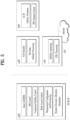
- FIG. 5 illustrates functional split between the NG-RAN and the 5GC according to an embodiment of the present disclosure.
- a gNB may provide functions including inter-cell radio resource management (RRM), radio admission control, measurement configuration and provision, and dynamic resource allocation.
- the AMF may provide functions such as non-access stratum (NAS) security and idle-state mobility processing.
- the UPF may provide functions including mobility anchoring and protocol data unit (PDU) processing.
- a session management function (SMF) may provide functions including UE Internet protocol (IP) address allocation and PDU session control.
- IP Internet protocol
- FIG. 6 illustrates a radio frame structure in NR, to which embodiment(s) of the present disclosure is applicable.
- a radio frame may be used for UL transmission and DL transmission in NR.
- a radio frame is 10ms in length, and may be defined by two 5-ms half-frames.
- An HF may include five 1-ms subframes.
- a subframe may be divided into one or more slots, and the number of slots in an SF may be determined according to a subcarrier spacing (SCS).
- SCS subcarrier spacing
- Each slot may include 12 or 14 OFDM(A) symbols according to a cyclic prefix (CP).
- CP cyclic prefix
- each slot may include 14 symbols, whereas in an extended CP (ECP) case, each slot may include 12 symbols.
- a symbol may be an OFDM symbol (or CP-OFDM symbol) or an SC-FDMA symbol (or DFT-s-OFDM symbol).
- An NR frequency band may be defined by two types of frequency ranges, FR1 and FR2.
- the numerals in each frequency range may be changed.
- the two types of frequency ranges may be given in Table 3.
- FR1 may be a "sub 6GHz range”
- FR2 may be an "above 6GHz range” called millimeter wave (mmW).
- mmW millimeter wave
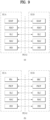
- l d refers to the number of symbols of a PSSCH (including a first symbol used for an AGC operation) in NR V2X.
- each number refers to an SL symbol index at which a PSSCH DMRS symbol is positioned according to PSCCH duration (2 symbols or 3 symbols).
- FIG. 17(a) illustrates the case in which l d is 6 and PSCCH duration is 2 symbols (PSSCH DMRS symbol index: 1 and 5), and FIG. 17(b) illustrates the case in which l d is13, PSCCH duration is 2 symbols, and the number of PSSCH DMRSs is 4 (PSSCH DMRS symbol index: 1, 4, 7, and 11).
- Half of a slot includes 6 symbols, it is necessary to support the case in which a l d value is 5 for an operation in the half slot.
- a l d value is 5 for an operation in the half slot.
- Table 8 the number and position of PSSCH DMRSs in one slot may be defined.
- l d in symbols DM-RS position l PSCCH duration 2 symbols
- PSCCH duration 3 symbols Number of PSSCH DM-RS Number of PSSCH DM-RS 2 3 4 2 3 4 5 1, 3 (or 1, 4) 1, 3 (or 1, 4) 6 1, 5 1, 5 7 1, 5 1, 5 1, 5 8 1, 5 1, 5 9 3, 8 1, 4, 7 4, 8 1, 4, 7 10 3, 8 1, 4, 7 4, 8 1, 4, 7 11 3, 10 1, 5, 9 1, 4, 7, 10 4, 10 1, 5, 9 1, 4, 7, 10
- the PSCCH duration may be restricted to 2 symbols.
- the number and position of PSSCH DMRSs in one slot may be defined.
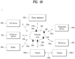
- FIG. 18 illustrates a communication system 1 applied to the present disclosure.
- the vehicles may include an unmanned aerial vehicle (UAV) (e.g., a drone).
- UAV unmanned aerial vehicle
- the XR device may include an augmented reality (AR)/virtual reality (VR)/mixed reality (MR) device and may be implemented in the form of a head-mounted device (HMD), a head-up display (HUD) mounted in a vehicle, a television, a smartphone, a computer, a wearable device, a home appliance device, a digital signage, a vehicle, a robot, etc.
- the hand-held device may include a smartphone, a smartpad, a wearable device (e.g., a smartwatch or a smartglasses), and a computer (e.g., a notebook).
- the home appliance may include a TV, a refrigerator, and a washing machine.
- the IoT device may include a sensor and a smartmeter.
- the BSs and the network may be implemented as wireless devices and a specific wireless device 200a may operate as a BS/network node with respect to other wireless devices.
- Wireless communication/connections 150a, 150b, or 150c may be established between the wireless devices 100a to 100f/BS 200, or BS 200/BS 200.
- the wireless communication/connections may be established through various RATs (e.g., 5G NR) such as UL/DL communication 150a, sidelink communication 150b (or, D2D communication), or inter BS communication (e.g. relay, integrated access backhaul (IAB)).
- the wireless devices and the BSs/the wireless devices may transmit/receive radio signals to/from each other through the wireless communication/connections 150a and 150b.
- the wireless communication/connections 150a and 150b may transmit/receive signals through various physical channels.
- various configuration information configuring processes various signal processing processes (e.g., channel encoding/decoding, modulation/demodulation, and resource mapping/demapping), and resource allocating processes, for transmitting/receiving radio signals, may be performed based on the various proposals of the present disclosure.
- various signal processing processes e.g., channel encoding/decoding, modulation/demodulation, and resource mapping/demapping
- resource allocating processes for transmitting/receiving radio signals
- FIG. 19 illustrates wireless devices applicable to the present disclosure.
- a first wireless device 100 and a second wireless device 200 may transmit radio signals through a variety of RATs (e.g., LTE and NR).
- ⁇ the first wireless device 100 and the second wireless device 200 ⁇ may correspond to ⁇ the wireless device 100x and the BS 200 ⁇ and/or ⁇ the wireless device 100x and the wireless device 100x ⁇ of FIG. 18 .
- the first wireless device 100 may include one or more processors 102 and one or more memories 104 and additionally further include one or more transceivers 106 and/or one or more antennas 108.
- the processor(s) 102 may control the memory(s) 104 and/or the transceiver(s) 106 and may be configured to implement the descriptions, functions, procedures, proposals, methods, and/or operational flowcharts disclosed in this document.
- the processor(s) 102 may process information within the memory(s) 104 to generate first information/signals and then transmit radio signals including the first information/signals through the transceiver(s) 106.
- the processor(s) 102 may receive radio signals including second information/signals through the transceiver 106 and then store information obtained by processing the second information/signals in the memory(s) 104.
- the memory(s) 104 may be connected to the processor(s) 102 and may store a variety of information related to operations of the processor(s) 102.
- the memory(s) 104 may store software code including commands for performing a part or the entirety of processes controlled by the processor(s) 102 or for performing the descriptions, functions, procedures, proposals, methods, and/or operational flowcharts disclosed in this document.
- the processor(s) 202 may receive radio signals including fourth information/signals through the transceiver(s) 106 and then store information obtained by processing the fourth information/signals in the memory(s) 204.
- the memory(s) 204 may be connected to the processor(s) 202 and may store a variety of information related to operations of the processor(s) 202.
- the memory(s) 204 may store software code including commands for performing a part or the entirety of processes controlled by the processor(s) 202 or for performing the descriptions, functions, procedures, proposals, methods, and/or operational flowcharts disclosed in this document.
- the processor(s) 202 and the memory(s) 204 may be a part of a communication modem/circuit/chip designed to implement RAT (e.g., LTE or NR).
- the transceiver(s) 206 may be connected to the processor(s) 202 and transmit and/or receive radio signals through one or more antennas 208.
- Each of the transceiver(s) 206 may include a transmitter and/or a receiver.
- the transceiver(s) 206 may be interchangeably used with RF unit(s).
- the wireless device may represent a communication modem/circuit/chip.
- One or more protocol layers may be implemented by, without being limited to, one or more processors 102 and 202.
- the one or more processors 102 and 202 may implement one or more layers (e.g., functional layers such as PHY, MAC, RLC, PDCP, RRC, and SDAP).
- the one or more processors 102 and 202 may generate one or more Protocol Data Units (PDUs) and/or one or more service data unit (SDUs) according to the descriptions, functions, procedures, proposals, methods, and/or operational flowcharts disclosed in this document.
- PDUs Protocol Data Units
- SDUs service data unit
- the one or more processors 102 and 202 may generate messages, control information, data, or information according to the descriptions, functions, procedures, proposals, methods, and/or operational flowcharts disclosed in this document.
- the one or more processors 102 and 202 may generate signals (e.g., baseband signals) including PDUs, SDUs, messages, control information, data, or information according to the descriptions, functions, procedures, proposals, methods, and/or operational flowcharts disclosed in this document and provide the generated signals to the one or more transceivers 106 and 206.
- the one or more processors 102 and 202 may receive the signals (e.g., baseband signals) from the one or more transceivers 106 and 206 and acquire the PDUs, SDUs, messages, control information, data, or information according to the descriptions, functions, procedures, proposals, methods, and/or operational flowcharts disclosed in this document.
- signals e.g., baseband signals
- the one or more processors 102 and 202 may be referred to as controllers, microcontrollers, microprocessors, or microcomputers.
- the one or more processors 102 and 202 may be implemented by hardware, firmware, software, or a combination thereof.
- ASICs application specific integrated circuits
- DSPs digital signal processors
- DSPDs digital signal processing devices
- PLDs programmable logic devices
- FPGAs field programmable gate arrays
- the descriptions, functions, procedures, proposals, methods, and/or operational flowcharts disclosed in this document may be implemented using firmware or software and the firmware or software may be configured to include the modules, procedures, or functions.
- Firmware or software configured to perform the descriptions, functions, procedures, proposals, methods, and/or operational flowcharts disclosed in this document may be included in the one or more processors 102 and 202 or stored in the one or more memories 104 and 204 so as to be driven by the one or more processors 102 and 202.
- the descriptions, functions, procedures, proposals, methods, and/or operational flowcharts disclosed in this document may be implemented using firmware or software in the form of code, commands, and/or a set of commands.
- the one or more memories 104 and 204 may be connected to the one or more processors 102 and 202 and store various types of data, signals, messages, information, programs, code, instructions, and/or commands.
- the one or more memories 104 and 204 may be configured by read-only memories (ROMs), random access memories (RAMs), electrically erasable programmable read-only memories (EPROMs), flash memories, hard drives, registers, cash memories, computer-readable storage media, and/or combinations thereof.
- the one or more memories 104 and 204 may be located at the interior and/or exterior of the one or more processors 102 and 202.
- the one or more memories 104 and 204 may be connected to the one or more processors 102 and 202 through various technologies such as wired or wireless connection.
- the one or more transceivers 106 and 206 may transmit user data, control information, and/or radio signals/channels, mentioned in the methods and/or operational flowcharts of this document, to one or more other devices.
- the one or more transceivers 106 and 206 may receive user data, control information, and/or radio signals/channels, mentioned in the descriptions, functions, procedures, proposals, methods, and/or operational flowcharts disclosed in this document, from one or more other devices.
- the one or more transceivers 106 and 206 may be connected to the one or more processors 102 and 202 and transmit and receive radio signals.
- the one or more processors 102 and 202 may perform control so that the one or more transceivers 106 and 206 may transmit user data, control information, or radio signals to one or more other devices.
- the one or more processors 102 and 202 may perform control so that the one or more transceivers 106 and 206 may receive user data, control information, or radio signals from one or more other devices.
- the one or more transceivers 106 and 206 may be connected to the one or more antennas 108 and 208 and the one or more transceivers 106 and 206 may be configured to transmit and receive user data, control information, and/or radio signals/channels, mentioned in the descriptions, functions, procedures, proposals, methods, and/or operational flowcharts disclosed in this document, through the one or more antennas 108 and 208.
- the one or more antennas may be a plurality of physical antennas or a plurality of logical antennas (e.g., antenna ports).
- the one or more transceivers 106 and 206 may convert received radio signals/channels etc.
- the one or more transceivers 106 and 206 may convert the user data, control information, radio signals/channels, etc. processed using the one or more processors 102 and 202 from the base band signals into the RF band signals.
- the one or more transceivers 106 and 206 may include (analog) oscillators and/or filters.
- FIG. 20 illustrates a vehicle or an autonomous driving vehicle applied to the present disclosure.
- the vehicle or autonomous driving vehicle may be implemented by a mobile robot, a car, a train, a manned/unmanned aerial vehicle (AV), a ship, etc.
- AV manned/unmanned aerial vehicle
- a vehicle or autonomous driving vehicle 100 may include an antenna unit 108, a communication unit 110, a control unit 120, a driving unit 140a, a power supply unit 140b, a sensor unit 140c, and an autonomous driving unit 140d.
- the antenna unit 108 may be configured as a part of the communication unit 110.
- the blocks 110/130/140a to 140d correspond to the blocks 110/130/140 of FIG. 43, respectively.
- the communication unit 110 may transmit and receive signals (e.g., data and control signals) to and from external devices such as other vehicles, BSs (e.g., gNBs and road side units), and servers.
- the control unit 120 may perform various operations by controlling elements of the vehicle or the autonomous driving vehicle 100.
- the control unit 120 may include an ECU.
- the driving unit 140a may cause the vehicle or the autonomous driving vehicle 100 to drive on a road.
- the driving unit 140a may include an engine, a motor, a powertrain, a wheel, a brake, a steering device, etc.
- the power supply unit 140b may supply power to the vehicle or the autonomous driving vehicle 100 and include a wired/wireless charging circuit, a battery, etc.
- the communication unit 110 may transfer information about a vehicle position, the autonomous driving path, and/or the driving plan to the external server.
- the external server may predict traffic information data using AI technology, etc., based on the information collected from vehicles or autonomous driving vehicles and provide the predicted traffic information data to the vehicles or the autonomous driving vehicles.
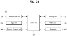
- a vehicle 100 may include a communication unit 110, a control unit 120, a memory unit 130, an I/O unit 140a, and a positioning unit 140b.
- the blocks 110 to 130/140a and 140b correspond to blocks 110 to 130/140 of FIG. 43.
- an XR device 100a may include a communication unit 110, a control unit 120, a memory unit 130, an I/O unit 140a, a sensor unit 140b, and a power supply unit 140c.
- the blocks 110 to 130/140a to 140c correspond to the blocks 110 to 130/140 of FIG. 43, respectively.
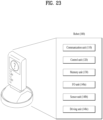
- FIG. 23 illustrates a robot applied to the present disclosure.
- the robot may be categorized into an industrial robot, a medical robot, a household robot, a military robot, etc., according to a used purpose or field.
Landscapes
- Engineering & Computer Science (AREA)
- Signal Processing (AREA)
- Computer Networks & Wireless Communication (AREA)
- Mobile Radio Communication Systems (AREA)
Claims (8)
- Verfahren zum Übertragen eines Phasenverfolgungs-Referenzsignals, PTRS, bezogen auf Sidelink durch ein Benutzergerät, UE, in einem drahtlosen Kommunikationssystem, wobei das Verfahren umfasst:Erzeugen (S1201) eines Demodulationsreferenzsignals, DMRS, bezogen auf einen gemeinsam genutzten physikalischen Sidelinkkanal, PSSCH;Erzeugen (S1202) des PTRS bezogen auf den PSSCH; undÜbertragen (S1203) mindestens eines Abschnitt des DMRS und des PTRS,wobei:ein Ressourcenbereich eines physikalischen Sidelinksteuerkanals, PSCCH, mit mindestens einem Teil eines Ressourcenbereichs des PSSCH überlappt,eine DMRS-Sequenz, die einer vorbestimmten Position in einem ersten PSSCH-Symbol zugeordnet ist, in dem das DMRS übertragen wird, zur Erzeugung des PTRS verwendet wird;die vorbestimmte Position einer Frequenzposition entspricht, auf der das PTRS übertragen wird; unddie vorbestimmte Position eine Frequenzposition enthält, bei der die Übertragung des erzeugten DMRS übersprungen wird.
- Verfahren nach Anspruch 1, wobei, basierend darauf, dass ein Ressourcenbereich eines physikalischen Sidelinksteuerkanals, PSCCH, vollständig mit einem Ressourcenbereich des PSSCH überlappt, das erste PSSCH-Symbol, in dem das DMRS übertragen wird, ein Symbol ist, in dem das DMRS zuerst nach dem Ressourcenbereich des PSCCH übertragen wird.
- Verfahren nach Anspruch 2, wobei der PSSCH und der PSCCH in einer Zeitachse, die dem ersten PSSCH-Symbol entspricht, Frequenzmultigeplext, FDM, werden.
- Verfahren nach Anspruch 1, wobei die Frequenzposition ein Unterträger ist.
- Verfahren nach Anspruch 1, wobei die Übertragung des PTRS übersprungen wird, wenn das PTRS mit dem PSCCH überlappt.
- Prozessor (102) zum Durchführen von Operationen für ein Benutzergerät, UE, (100) zum Übertragen eines Phasenverfolgungsreferenzsignals, PTRS, in einem drahtlosen Kommunikationssystem, wobei die Operationen umfassen:
wobei die Operationen umfassen:Erzeugen eines Demodulationsreferenzsignals, DMRS, bezogen auf einen gemeinsam genutzten physikalischen Sidelinkkanal, PSSCH;Erzeugen des PTRS bezogen auf den PSSCH; undÜbertragen mindestens eines Abschnitt des DMRS und des PTRS,ein Ressourcenbereich eines physikalischen Sidelinksteuerkanals, PSCCH, überlappt mit mindestens einem Teil eines Ressourcenbereichs des PSSCH,wobei eine DMRS-Sequenz, die einer vorbestimmten Position in einem ersten PSSCH-Symbol zugeordnet ist, in dem das DMRS übertragen wird, zur Erzeugung des PTRS verwendet wird,die vorbestimmte Position entspricht einer Frequenzposition, auf der das PTRS übertragen wird, unddie vorbestimmte Position enthält eine Frequenzposition, bei der die Übertragung des erzeugten DMRS übersprungen wird. - Nichtflüchtiges, computerlesbares Aufzeichnungsmedium (104) zum Speichern mindestens eines Computerprogramms, das einen Befehl enthält, der es mindestens einem Prozessor (102) ermöglicht, Operationen eines Benutzergeräts, UE, (100) durchzuführen, wenn es von dem mindestens einen Prozessor (102) ausgeführt wird, wobei die Operationen umfassen:Erzeugen eines Demodulationsreferenzsignals, DMRS, bezogen auf einen gemeinsam genutzten physikalischen Sidelinkkanal, PSSCH;Erzeugen des PTRS bezogen auf den PSSCH; undÜbertragen mindestens eines Abschnitt des DMRS und des PTRS,ein Ressourcenbereich eines physikalischen Sidelinksteuerkanals, PSCCH, überlappt mit mindestens einem Teil eines Ressourcenbereichs des PSSCH,wobei eine DMRS-Sequenz, die einer vorbestimmten Position in einem ersten PSSCH-Symbol zugeordnet ist, in dem das DMRS übertragen wird, zur Erzeugung des PTRS verwendet wird,die vorbestimmte Position entspricht einer Frequenzposition, auf der das PTRS übertragen wird, unddie vorbestimmte Position enthält eine Frequenzposition, bei der die Übertragung des erzeugten DMRS übersprungen wird.
- Prozessor nach Anspruch 6, wobei der Prozessor in einem Benutzergerät, UE, (100) enthalten ist.
Applications Claiming Priority (5)
| Application Number | Priority Date | Filing Date | Title |
|---|---|---|---|
| KR20200006809 | 2020-01-17 | ||
| KR20200007513 | 2020-01-20 | ||
| KR20200010771 | 2020-01-30 | ||
| KR20200017982 | 2020-02-13 | ||
| PCT/KR2021/000680 WO2021145751A1 (ko) | 2020-01-17 | 2021-01-18 | 무선통신시스템에서 사이드링크 ptrs에 관련된 ue의 동작 방법 |
Publications (3)
| Publication Number | Publication Date |
|---|---|
| EP4089950A1 EP4089950A1 (de) | 2022-11-16 |
| EP4089950A4 EP4089950A4 (de) | 2023-06-28 |
| EP4089950B1 true EP4089950B1 (de) | 2025-04-16 |
Family
ID=76863906
Family Applications (1)
| Application Number | Title | Priority Date | Filing Date |
|---|---|---|---|
| EP21741912.6A Active EP4089950B1 (de) | 2020-01-17 | 2021-01-18 | Endgerätebetriebsverfahren in zusammenhang mit sidelink-ptrs in einem drahtloskommunikationssystem |
Country Status (6)
| Country | Link |
|---|---|
| US (2) | US11764927B2 (de) |
| EP (1) | EP4089950B1 (de) |
| JP (1) | JP7379718B2 (de) |
| KR (1) | KR102629748B1 (de) |
| CN (1) | CN114982186B (de) |
| WO (1) | WO2021145751A1 (de) |
Families Citing this family (8)
| Publication number | Priority date | Publication date | Assignee | Title |
|---|---|---|---|---|
| US12302362B2 (en) * | 2020-02-13 | 2025-05-13 | Panasonic Intellectual Property Corporation Of America | Terminal, and communication method |
| CN113518428B (zh) * | 2020-04-09 | 2024-08-20 | 维沃移动通信有限公司 | 资源确定方法和设备 |
| EP3965355B1 (de) * | 2020-09-02 | 2025-10-08 | Samsung Electronics Co., Ltd. | Vorrichtung und verfahren zur effektiven abbildung eines referenzsignals für die v2x-kommunikation in einem drahtlosen kommunikationssystem |
| WO2023050118A1 (en) * | 2021-09-29 | 2023-04-06 | Zte Corporation | Phase tracking reference signal pattern configuration and signaling in wireless communication system |
| CN116015569A (zh) * | 2021-10-21 | 2023-04-25 | 北京紫光展锐通信技术有限公司 | 一种偏移值确定方法、装置、芯片及模组设备 |
| EP4661562A1 (de) * | 2023-01-30 | 2025-12-10 | LG Electronics Inc. | Verfahren und vorrichtung zur durchführung von drahtloser kommunikation im zusammenhang mit positionierung |
| US20250023691A1 (en) * | 2023-07-10 | 2025-01-16 | Qualcomm Incorporated | Sidelink pssch demodulation reference signal |
| US20250142613A1 (en) * | 2023-10-26 | 2025-05-01 | Qualcomm Incorporated | Handling an uplink resource muting pattern that overlaps with a phase tracking reference signal in a subband full duplex operation |
Family Cites Families (12)
| Publication number | Priority date | Publication date | Assignee | Title |
|---|---|---|---|---|
| US10448365B2 (en) * | 2016-04-12 | 2019-10-15 | Telefonaktiebolaget Lm Ericsson (Publ) | Method and an apparatus for reference signal and mapping for sidelink communications |
| CN108259401B (zh) * | 2016-12-28 | 2020-09-15 | 电信科学技术研究院 | 参考信号发送方法和相位噪声确定方法及相关装置 |
| JP2020057825A (ja) * | 2017-02-02 | 2020-04-09 | シャープ株式会社 | 基地局装置、端末装置、通信方法、および、集積回路 |
| CN108632005B (zh) * | 2017-03-24 | 2023-12-15 | 华为技术有限公司 | 一种参考信号传输方法、装置及系统 |
| CN109391448B (zh) * | 2017-08-11 | 2021-10-01 | 华为技术有限公司 | 一种信息传输方法及装置 |
| ES2908256T3 (es) * | 2017-11-17 | 2022-04-28 | Ericsson Telefon Ab L M | Técnica para configurar una señal de referencia de seguimiento de fase |
| WO2019235756A1 (ko) * | 2018-06-07 | 2019-12-12 | 엘지전자 주식회사 | 무선 통신 시스템에서 단말과 기지국 간 위상 트래킹 참조 신호를 송수신하는 방법 및 이를 지원하는 장치 |
| EP3834315A4 (de) * | 2018-08-09 | 2022-05-11 | Fg Innovation Company Limited | Verfahren und vorrichtung zur durchführung einer sidelink-kommunikation in drahtloskommunikationssystemen |
| WO2020067697A1 (ko) * | 2018-09-28 | 2020-04-02 | 삼성전자 주식회사 | 무선 통신 시스템에서 사용자 구분을 위한 제어정보 전송 방법 및 장치 |
| US12356442B2 (en) * | 2019-03-04 | 2025-07-08 | Lg Electronics Inc. | Method and device for measuring sidelink channel in wireless communication system |
| KR20220093188A (ko) * | 2019-11-05 | 2022-07-05 | 엘지전자 주식회사 | 무선통신시스템에서 sci 관련 ue의 동작 방법 |
| EP3850900B1 (de) * | 2019-11-28 | 2023-08-16 | Apple Inc. | V2x-sidelink-kanaldesign |
-
2021
- 2021-01-18 EP EP21741912.6A patent/EP4089950B1/de active Active
- 2021-01-18 KR KR1020227022061A patent/KR102629748B1/ko active Active
- 2021-01-18 CN CN202180009321.6A patent/CN114982186B/zh active Active
- 2021-01-18 WO PCT/KR2021/000680 patent/WO2021145751A1/ko not_active Ceased
- 2021-01-18 JP JP2022542940A patent/JP7379718B2/ja active Active
-
2022
- 2022-06-28 US US17/809,472 patent/US11764927B2/en active Active
-
2023
- 2023-03-29 US US18/192,036 patent/US11997037B2/en active Active
Also Published As
| Publication number | Publication date |
|---|---|
| CN114982186A (zh) | 2022-08-30 |
| EP4089950A4 (de) | 2023-06-28 |
| KR102629748B1 (ko) | 2024-01-29 |
| US11997037B2 (en) | 2024-05-28 |
| US11764927B2 (en) | 2023-09-19 |
| EP4089950A1 (de) | 2022-11-16 |
| WO2021145751A1 (ko) | 2021-07-22 |
| US20230299909A1 (en) | 2023-09-21 |
| JP7379718B2 (ja) | 2023-11-14 |
| KR20220106813A (ko) | 2022-07-29 |
| CN114982186B (zh) | 2024-06-07 |
| US20220376859A1 (en) | 2022-11-24 |
| JP2023510010A (ja) | 2023-03-10 |
Similar Documents
| Publication | Publication Date | Title |
|---|---|---|
| US20220264619A1 (en) | Operation method of ue associated with sci in wireless communication system | |
| EP4089950B1 (de) | Endgerätebetriebsverfahren in zusammenhang mit sidelink-ptrs in einem drahtloskommunikationssystem | |
| US11564279B2 (en) | Method of operating UE in relation to as configuration in wireless communication system | |
| US12610379B2 (en) | Method for operating relay UE related to sidelink relay in wireless communication system | |
| US11778592B2 (en) | 2ND stage SCI-related operation method of UE in wireless communication system | |
| US11903084B2 (en) | Sidelink discovery-related operation method in wireless communication system | |
| US20220232665A1 (en) | Method and apparatus for operating a ue related to sidelink drx in a wireless communication system | |
| US11096239B2 (en) | Method of operating UE in relation to release of PC5 unicast link in wireless communication system | |
| US12256307B2 (en) | Method for operating link quality-related relay UE in wireless communication system | |
| US20220053418A1 (en) | Method of operating a ue related to a sidelink measurement report in a wireless communication system | |
| US20230217518A1 (en) | Operation method of ue related to system information and sidelink relay in wireless communication system | |
| US11622400B2 (en) | Method of operating UE in relation to release of sidelink RRC connection in wireless communication system | |
| US20230300905A1 (en) | Method for operating ue related to sidelink timer in wireless communication system | |
| US20230224951A1 (en) | Operation method of relay ue in wireless communication system | |
| US20240097855A1 (en) | Sidelink operating method of csi-rs transmission-related ue in wireless communication system | |
| US11671960B2 (en) | Operating method of UE related to SCI transmission in wireless communication system | |
| US12432793B2 (en) | Operating method of UE related to relay in wireless communication system | |
| US12302296B2 (en) | UE operation method related to determining number of slots in wireless communication system | |
| US12574166B2 (en) | Method for retransmission-related operation of relay UE in wireless communication system | |
| US20230309064A1 (en) | Operating method of relay ue related to bwp in wireless communication system | |
| US12389268B2 (en) | Operation method of UE receiving V2X-related message in wireless communication system | |
| US12363693B2 (en) | Method for operating UE related to CBR in wireless communication system | |
| US20230156679A1 (en) | Method for receiving pscch by ps ue in wireless communication system |
Legal Events
| Date | Code | Title | Description |
|---|---|---|---|
| STAA | Information on the status of an ep patent application or granted ep patent |
Free format text: STATUS: THE INTERNATIONAL PUBLICATION HAS BEEN MADE |
|
| PUAI | Public reference made under article 153(3) epc to a published international application that has entered the european phase |
Free format text: ORIGINAL CODE: 0009012 |
|
| STAA | Information on the status of an ep patent application or granted ep patent |
Free format text: STATUS: REQUEST FOR EXAMINATION WAS MADE |
|
| 17P | Request for examination filed |
Effective date: 20220810 |
|
| AK | Designated contracting states |
Kind code of ref document: A1 Designated state(s): AL AT BE BG CH CY CZ DE DK EE ES FI FR GB GR HR HU IE IS IT LI LT LU LV MC MK MT NL NO PL PT RO RS SE SI SK SM TR |
|
| DAV | Request for validation of the european patent (deleted) | ||
| DAX | Request for extension of the european patent (deleted) | ||
| A4 | Supplementary search report drawn up and despatched |
Effective date: 20230601 |
|
| RIC1 | Information provided on ipc code assigned before grant |
Ipc: H04J 13/10 20110101ALI20230525BHEP Ipc: H04W 72/04 20090101ALI20230525BHEP Ipc: H04W 4/40 20180101ALI20230525BHEP Ipc: H04W 56/00 20090101ALI20230525BHEP Ipc: H04L 5/00 20060101AFI20230525BHEP |
|
| STAA | Information on the status of an ep patent application or granted ep patent |
Free format text: STATUS: EXAMINATION IS IN PROGRESS |
|
| 17Q | First examination report despatched |
Effective date: 20240228 |
|
| GRAP | Despatch of communication of intention to grant a patent |
Free format text: ORIGINAL CODE: EPIDOSNIGR1 |
|
| STAA | Information on the status of an ep patent application or granted ep patent |
Free format text: STATUS: GRANT OF PATENT IS INTENDED |
|
| INTG | Intention to grant announced |
Effective date: 20241115 |
|
| GRAS | Grant fee paid |
Free format text: ORIGINAL CODE: EPIDOSNIGR3 |
|
| GRAA | (expected) grant |
Free format text: ORIGINAL CODE: 0009210 |
|
| STAA | Information on the status of an ep patent application or granted ep patent |
Free format text: STATUS: THE PATENT HAS BEEN GRANTED |
|
| AK | Designated contracting states |
Kind code of ref document: B1 Designated state(s): AL AT BE BG CH CY CZ DE DK EE ES FI FR GB GR HR HU IE IS IT LI LT LU LV MC MK MT NL NO PL PT RO RS SE SI SK SM TR |
|
| REG | Reference to a national code |
Ref country code: GB Ref legal event code: FG4D |
|
| REG | Reference to a national code |
Ref country code: CH Ref legal event code: EP Ref country code: DE Ref legal event code: R096 Ref document number: 602021029251 Country of ref document: DE |
|
| REG | Reference to a national code |
Ref country code: IE Ref legal event code: FG4D |
|
| REG | Reference to a national code |
Ref country code: NL Ref legal event code: MP Effective date: 20250416 |
|
| PG25 | Lapsed in a contracting state [announced via postgrant information from national office to epo] |
Ref country code: NL Free format text: LAPSE BECAUSE OF FAILURE TO SUBMIT A TRANSLATION OF THE DESCRIPTION OR TO PAY THE FEE WITHIN THE PRESCRIBED TIME-LIMIT Effective date: 20250416 |
|
| REG | Reference to a national code |
Ref country code: AT Ref legal event code: MK05 Ref document number: 1786575 Country of ref document: AT Kind code of ref document: T Effective date: 20250416 |
|
| PG25 | Lapsed in a contracting state [announced via postgrant information from national office to epo] |
Ref country code: FI Free format text: LAPSE BECAUSE OF FAILURE TO SUBMIT A TRANSLATION OF THE DESCRIPTION OR TO PAY THE FEE WITHIN THE PRESCRIBED TIME-LIMIT Effective date: 20250416 Ref country code: PT Free format text: LAPSE BECAUSE OF FAILURE TO SUBMIT A TRANSLATION OF THE DESCRIPTION OR TO PAY THE FEE WITHIN THE PRESCRIBED TIME-LIMIT Effective date: 20250818 Ref country code: ES Free format text: LAPSE BECAUSE OF FAILURE TO SUBMIT A TRANSLATION OF THE DESCRIPTION OR TO PAY THE FEE WITHIN THE PRESCRIBED TIME-LIMIT Effective date: 20250416 |
|
| REG | Reference to a national code |
Ref country code: LT Ref legal event code: MG9D |
|
| PG25 | Lapsed in a contracting state [announced via postgrant information from national office to epo] |
Ref country code: NO Free format text: LAPSE BECAUSE OF FAILURE TO SUBMIT A TRANSLATION OF THE DESCRIPTION OR TO PAY THE FEE WITHIN THE PRESCRIBED TIME-LIMIT Effective date: 20250716 Ref country code: GR Free format text: LAPSE BECAUSE OF FAILURE TO SUBMIT A TRANSLATION OF THE DESCRIPTION OR TO PAY THE FEE WITHIN THE PRESCRIBED TIME-LIMIT Effective date: 20250717 |
|
| PG25 | Lapsed in a contracting state [announced via postgrant information from national office to epo] |
Ref country code: PL Free format text: LAPSE BECAUSE OF FAILURE TO SUBMIT A TRANSLATION OF THE DESCRIPTION OR TO PAY THE FEE WITHIN THE PRESCRIBED TIME-LIMIT Effective date: 20250416 |
|
| PG25 | Lapsed in a contracting state [announced via postgrant information from national office to epo] |
Ref country code: BG Free format text: LAPSE BECAUSE OF FAILURE TO SUBMIT A TRANSLATION OF THE DESCRIPTION OR TO PAY THE FEE WITHIN THE PRESCRIBED TIME-LIMIT Effective date: 20250416 |
|
| PG25 | Lapsed in a contracting state [announced via postgrant information from national office to epo] |
Ref country code: HR Free format text: LAPSE BECAUSE OF FAILURE TO SUBMIT A TRANSLATION OF THE DESCRIPTION OR TO PAY THE FEE WITHIN THE PRESCRIBED TIME-LIMIT Effective date: 20250416 |
|
| PG25 | Lapsed in a contracting state [announced via postgrant information from national office to epo] |
Ref country code: AT Free format text: LAPSE BECAUSE OF FAILURE TO SUBMIT A TRANSLATION OF THE DESCRIPTION OR TO PAY THE FEE WITHIN THE PRESCRIBED TIME-LIMIT Effective date: 20250416 |
|
| PG25 | Lapsed in a contracting state [announced via postgrant information from national office to epo] |
Ref country code: RS Free format text: LAPSE BECAUSE OF FAILURE TO SUBMIT A TRANSLATION OF THE DESCRIPTION OR TO PAY THE FEE WITHIN THE PRESCRIBED TIME-LIMIT Effective date: 20250716 |
|
| PG25 | Lapsed in a contracting state [announced via postgrant information from national office to epo] |
Ref country code: IS Free format text: LAPSE BECAUSE OF FAILURE TO SUBMIT A TRANSLATION OF THE DESCRIPTION OR TO PAY THE FEE WITHIN THE PRESCRIBED TIME-LIMIT Effective date: 20250816 |
|
| PG25 | Lapsed in a contracting state [announced via postgrant information from national office to epo] |
Ref country code: LV Free format text: LAPSE BECAUSE OF FAILURE TO SUBMIT A TRANSLATION OF THE DESCRIPTION OR TO PAY THE FEE WITHIN THE PRESCRIBED TIME-LIMIT Effective date: 20250416 |
|
| PG25 | Lapsed in a contracting state [announced via postgrant information from national office to epo] |
Ref country code: DK Free format text: LAPSE BECAUSE OF FAILURE TO SUBMIT A TRANSLATION OF THE DESCRIPTION OR TO PAY THE FEE WITHIN THE PRESCRIBED TIME-LIMIT Effective date: 20250416 Ref country code: SM Free format text: LAPSE BECAUSE OF FAILURE TO SUBMIT A TRANSLATION OF THE DESCRIPTION OR TO PAY THE FEE WITHIN THE PRESCRIBED TIME-LIMIT Effective date: 20250416 |
|
| REG | Reference to a national code |
Ref country code: DE Ref legal event code: R097 Ref document number: 602021029251 Country of ref document: DE |
|
| PG25 | Lapsed in a contracting state [announced via postgrant information from national office to epo] |
Ref country code: CZ Free format text: LAPSE BECAUSE OF FAILURE TO SUBMIT A TRANSLATION OF THE DESCRIPTION OR TO PAY THE FEE WITHIN THE PRESCRIBED TIME-LIMIT Effective date: 20250416 |
|
| PG25 | Lapsed in a contracting state [announced via postgrant information from national office to epo] |
Ref country code: EE Free format text: LAPSE BECAUSE OF FAILURE TO SUBMIT A TRANSLATION OF THE DESCRIPTION OR TO PAY THE FEE WITHIN THE PRESCRIBED TIME-LIMIT Effective date: 20250416 |
|
| PG25 | Lapsed in a contracting state [announced via postgrant information from national office to epo] |
Ref country code: SK Free format text: LAPSE BECAUSE OF FAILURE TO SUBMIT A TRANSLATION OF THE DESCRIPTION OR TO PAY THE FEE WITHIN THE PRESCRIBED TIME-LIMIT Effective date: 20250416 |
|
| PG25 | Lapsed in a contracting state [announced via postgrant information from national office to epo] |
Ref country code: IT Free format text: LAPSE BECAUSE OF FAILURE TO SUBMIT A TRANSLATION OF THE DESCRIPTION OR TO PAY THE FEE WITHIN THE PRESCRIBED TIME-LIMIT Effective date: 20250416 |
|
| PLBE | No opposition filed within time limit |
Free format text: ORIGINAL CODE: 0009261 |
|
| STAA | Information on the status of an ep patent application or granted ep patent |
Free format text: STATUS: NO OPPOSITION FILED WITHIN TIME LIMIT |
|
| REG | Reference to a national code |
Ref country code: CH Ref legal event code: L10 Free format text: ST27 STATUS EVENT CODE: U-0-0-L10-L00 (AS PROVIDED BY THE NATIONAL OFFICE) Effective date: 20260225 |
|
| 26N | No opposition filed |
Effective date: 20260119 |
|
| PGFP | Annual fee paid to national office [announced via postgrant information from national office to epo] |
Ref country code: DE Payment date: 20251208 Year of fee payment: 6 |