EP4091735A2 - Outil composite - Google Patents
Outil composite Download PDFInfo
- Publication number
- EP4091735A2 EP4091735A2 EP22170558.5A EP22170558A EP4091735A2 EP 4091735 A2 EP4091735 A2 EP 4091735A2 EP 22170558 A EP22170558 A EP 22170558A EP 4091735 A2 EP4091735 A2 EP 4091735A2
- Authority
- EP
- European Patent Office
- Prior art keywords
- tool
- movement
- composite tool
- sheet metal
- metal elements
- Prior art date
- Legal status (The legal status is an assumption and is not a legal conclusion. Google has not performed a legal analysis and makes no representation as to the accuracy of the status listed.)
- Pending
Links
Images


Classifications
-
- B—PERFORMING OPERATIONS; TRANSPORTING
- B21—MECHANICAL METAL-WORKING WITHOUT ESSENTIALLY REMOVING MATERIAL; PUNCHING METAL
- B21D—WORKING OR PROCESSING OF SHEET METAL OR METAL TUBES, RODS OR PROFILES WITHOUT ESSENTIALLY REMOVING MATERIAL; PUNCHING METAL
- B21D39/00—Application of procedures in order to connect objects or parts, e.g. coating with sheet metal otherwise than by plating; Tube expanders
- B21D39/03—Application of procedures in order to connect objects or parts, e.g. coating with sheet metal otherwise than by plating; Tube expanders of sheet metal otherwise than by folding
- B21D39/034—Joining superposed plates by piercing
-
- B—PERFORMING OPERATIONS; TRANSPORTING
- B25—HAND TOOLS; PORTABLE POWER-DRIVEN TOOLS; MANIPULATORS
- B25B—TOOLS OR BENCH DEVICES NOT OTHERWISE PROVIDED FOR, FOR FASTENING, CONNECTING, DISENGAGING, OR HOLDING
- B25B27/00—Hand tools, specially adapted for fitting together or separating parts or objects whether or not involving some deformation, not otherwise provided for
- B25B27/14—Hand tools, specially adapted for fitting together or separating parts or objects whether or not involving some deformation, not otherwise provided for for assembling objects other than by press fit or detaching same
Definitions
- the present invention relates to a compound tool for connecting sheet metal elements, in particular for use by a user in connection with drywall work.
- Composite tools for sheet metal elements are known from the prior art, which are used in particular in the context of dry construction work, the composite tools being used to connect a large number of sheet metal elements to one another in order to provide a support structure for a dry construction element on which in a subsequent operation appropriate drywall, such as plasterboard or gypsum fiber boards, are attached.
- the support structure can be extremely time-consuming and labor-intensive and include a large number of work steps, in the course of which the usually standardized sheet metal elements , which are also called profile elements, have to be connected to one another in a reliable manner in order to realize the desired geometric shape in a complex manner and with the usually limited working space available.
- One object of the present invention is therefore to provide a composite tool that enables sheet metal elements to be connected more efficiently, in particular in the context of dry construction work.
- a composite tool for connecting sheet metal elements in particular for use by a user in the context of drywall work, is provided with a matrix element and a tool bit, the compound tool being set up to translate the tool bit from a starting position along a first direction of movement into the die element and in the course of this to penetrate sheet metal elements arranged in the starting position between the tool chisel and the die element, with partial areas of the penetrated sheet metal elements being brought into contact with a contour of the die element by bending plastic deformation in such a way that over the plastically deformed partial areas a positive connection is made between the individual sheet metal elements.
- the composite tool includes an electric operated drive device configured to move the tool bit back and forth along the first direction of movement and to provide a force required to penetrate the sheet metal members.
- the partial areas are areas of at least two sheet metal elements to be connected to one another in an environment around a penetration point of the tool bit, which is plastically deformed in the course of a progressive movement of the tool bit and partially on the contour or on a contact contour of the die element (as a shape-determining element) are brought into contact or run at least partially parallel to said contact contour, with the contact contour ensuring that each form-fitting connection produced is designed as similarly as possible and the sub-areas are not deformed in any way that is always different, but rather in a way that is caused by the interaction of an outer contour of the tool chisel and the contact contour of the die element.
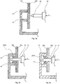
- the plastically deformed sub-areas can be seen as tabs that are bent over together, which at least partially restrict relative movements between the sheet metal elements (see also Figures 3b, 3c ).
- the required force is to be understood as the force provided on the tool bit along the first direction of movement, which is required for penetration and for the subsequent plastic deformation of the sheet metal elements or partial areas, but also for a subsequent extraction of the tool bit from the previously penetrated sheet metal elements and which is applied or provided entirely by the drive device of the composite tool according to the invention.
- the invention in the exemplary comparison to the composite tongs from the WO 2007/093145 A1 provided a composite tool that enables sheet metal elements to be connected far more efficiently, with a time aspect in the sense of a throughput rate, which can be specified, for example, as a total number of connections made over a working day, to assess efficiency, a processing quality of the connections made positive connections as well as exhaustion of the user.
- the compound tool advantageously only has to be positioned by the user on the sheet metal elements to be connected. All subsequent work steps for connecting the sheet metal elements are carried out by the composite tool itself, in particular by the electrically operated drive device, without the user having to do any significant work.
- the penetration of the sheet metal elements, the associated plastic deformation of the sub-areas to produce the form-fitting connection and the retraction and separation of the tool bit from the successfully connected sheet metal elements are carried out fully automatically by the composite tool, whereby the user only has to hold it in position.
- the composite tool of the present invention can be used continuously and repeatedly by the user without undue fatigue, resulting in less to no user rest breaks due to fatigue, which in turn increases the throughput rate of connections made over time.
- the processing quality of the connection points is no longer dependent on the user being exhausted at the moment, since the compound tool has processing parameters, such as penetration speed or force progression, in several successive work steps essentially retained, which obviously cannot be guaranteed with purely manual use.
- the force provided by the drive device means that more than just two sheet metal elements can also be connected to one another in a simple manner, since the force to be applied manually is no longer a limiting factor in connection production.
- the movement of the tool bit along the first direction of movement is preferably a completely linear, purely translational movement.
- the necessary installation space can be significantly reduced in comparison to a partially rotating movement, for example, with the tool chisel being guided particularly precisely through the sheet metal elements at the same time without becoming wedged in them.
- the composite tool comprises an energy storage device that is set up to store electrical energy and to supply the drive device with electrical energy, the energy storage device being in particular a rechargeable battery.
- a composite tool that can be used in a completely mobile manner is provided, which works independently of an energy source arranged outside of the composite tool and corresponding connection means, such as power cables, and can therefore be used in any location, including in places that are difficult to access, without having to the manual power of a user must be resorted to in the course of handling.
- the composite tool can also be used in places where no external energy supply is available per se, but would first have to be set up, which in turn would mean additional time expenditure.
- the energy storage device is detachably connected to a housing of the composite tool in such a way that the energy storage device can be completely decoupled from the composite tool.
- the energy storage device can be exchanged quickly and easily for a charged energy storage device with a high energy level during mobile use of the composite tool in the event of a low energy level, which in turn means only a brief interruption of the connection work.
- the composite tool preferably includes a control unit which is coupled to the drive device and is set up to control the drive device on the basis of user inputs received via input means.
- this is an operating lever or button which, after being actuated by the user, causes the control unit to start the drive device and start the translational movement of the tool bit from the starting position to the end position and back to the to carry out the initial position.
- the composite tool preferably comprises input means for user inputs, which are each set up to cause the control unit to adapt one or more machining parameters of a group of machining parameters as a function of the user input, the group of machining parameters having an average speed of the translatory movement of the tool bit, a relative the end position of the tool bit that can be specified relative to the housing or the die element, a maximum force to be transmitted to the tool bit, and a direction of movement of the translational movement of the tool bit.
- the user can adapt the machining parameters of the composite tool according to his wishes and thus react to application-specific features, e.g. different material of individual sheet metal elements or the like.
- the drive device comprises a drive unit providing a rotary movement and a transmission gear, with the transmission gear being designed to convert the provided rotary movement of the drive unit into the translatory one Translate movement of the tool bit along the first direction of movement.
- the step-up gear is preferably composed of a plurality of gear stages, each of which in turn is a gear.
- the step-up gear consists of a first and a second gear stage, the first gear stage being set up to convert the rotational movement of the drive unit with an output speed into a rotational movement with a nominal speed specified for the second gear stage via at least one pair of gear wheels.
- the second gear stage is in turn set up to convert or translate the rotational movement provided via the first gear stage at the nominal speed into the translatory movement of the tool chisel.
- the drive unit can be selected as freely as possible, the speed of which is specifically adapted to the nominal speed via the first gear stage, which in turn determines a speed of the translational movement provided via the second gear stage.
- the step-up gear comprises a crank drive step-up with a crank element driven in rotation via the drive unit and a connecting element coupled thereto for transmitting the translational movement to the tool bit.
- the crank drive transmission offers a relatively inexpensive variant for converting or translating a rotary movement into a translatory movement, whereby, in contrast to other types of translation, an alternating translatory movement can be provided directly without reversing a direction of rotation or a direction of rotation of the rotary movement of the drive unit.
- a forward movement of the tool bit along the first direction of movement after reaching the end position can change directly into a backward movement counter to the first direction of movement, without the direction of rotation of the drive unit having to be switched.
- the connecting element is a connecting rod rotatably connected both to the crank element and to the tool bit.
- the connecting rod is connected to the crank element via a rotary joint which is arranged eccentrically with respect to the latter, it being possible for the rotary joint to be, for example, a plain bearing or a roller bearing.
- a force profile of the force acting on the tool chisel in (or against) the first direction of movement is not constant when using a crank drive transmission, but depends on a current configuration of the crank element and connecting element. Thus, no force is usually provided at the reversal points of the alternating translational movement of the tool bit, since in these configurations no torque of the crank element can be converted into a force along (or against) the first direction of movement.
- crank drive transmission is designed as a Scotch-Yoke crank drive, with the connecting element being designed as a sliding guide for an eccentrically arranged pin of the crank element.
- the Scotch-Yoke crank drive which is sometimes also referred to as link guide, represents an alternative to the connecting rod-based crank drive, which in contrast takes up more space, but allows a far more harmonious transmission of power and movement, in the course of which essentially sinusoidal curves of force and displacement of the tool bit as a function of a twisting angle of the crank element (also called crank angle), with one period of said sinusoidal curves corresponding to a complete revolution of the crank element.
- the slideway of the Scotch-Yoke crank mechanism is connected to the tool bit so that the force (and motion) transmitted by contact between the slideway and the crank pin is also transmitted directly to the tool bit.
- the transmission gear comprises a spindle and a spindle nut that engages with it, which are arranged in such a way that a rotation of the spindle is translated into a longitudinal movement of the spindle nut along the first direction of movement, or that a rotation of the spindle nut is translated into a longitudinal movement of the spindle is implemented along the first direction of movement.
- the respective longitudinal movement is transmitted to the tool bit either directly or indirectly, e.g. via an elastic or viscoelastic element, in order to provide its translatory movement in the first direction of movement (or counter to the first direction of movement).
- the step-up gear also comprises a worm gear with a worm shaft driven by the drive unit and a worm wheel meshing with the worm shaft.
- the worm shaft arranged on the drive unit side provides a rotational movement that is transmitted to the worm wheel in engagement with it, whereby compared to a conventional Spur gear pairing much higher gear ratios can be implemented.
- a self-locking transmission mechanism in the transmission gear is provided by the worm gear, which only allows a transmission of movement in one direction.
- the die element is attached to a bracket-shaped die holder, which is connected to the housing of the composite tool in such a way that in the starting position the tool bit and the die element are spaced apart from one another in such a way that sheet metal elements of a predefined width and thickness can be arranged in between.
- the bow-shaped configuration ensures that the die element is arranged at a distance, with a connection made by the die holder to the housing of the composite tool having a relatively large distance to a connecting line between the tool bit and the die element along the first direction of movement, so that even wide sheet metal elements can be arranged between the die element and the tool holder without any problems and still be penetrated almost in the middle by the tool bit.
- the die holder preferably has additional reinforcement elements, so that it has increased flexural rigidity when a force acts on the die element in the direction of the first direction of movement.
- the matrix element and/or the matrix holder can be exchanged.
- the die holder can be rotated relative to the housing of the composite tool about an axis of rotation, which runs in particular along or parallel to the first direction of movement, and/or the die holder can be rotated back and forth relative to the housing of the composite tool along a second direction of movement, which in particular runs parallel to the first direction of movement, displaceable.
- the relative arrangement of the die holder and die element with respect to the housing can be varied in order to provide the optimal configuration depending on the application and user preferences.
- a right-handed user can choose an angular position of the die holder rotated by 180° compared to a left-handed user in order to provide an optimal view of the sheet metal elements to be connected without the die holder obstructing them.
- the tool chisel comprises a chisel tip designed to penetrate the sheet metal elements, which is releasably connected to a carrier element of the tool chisel that is movably mounted with respect to the housing along the first direction of movement, in particular via a pair of threads.
- the part of the tool chisel that is in contact with the sheet metal elements is kept exchangeable, so that not only can chisel tips that have been adapted to die elements that may have a different shape be exchanged, but also worn-out chisel tips that may have a blunt cutting edge can be replaced without much effort by a exchange a new chisel tip, which in turn increases machining quality without having to accept long downtimes due to complex maintenance work, e.g. grinding work on the cutting edge.
- the housing of the composite tool comprises a holding section that can be enclosed by one of the user's hands and that acts as an interface between the user and the composite tool during handling, the holding section being designed in such a way that it is held in place by the user during handling State the first direction of movement is substantially parallel to a longitudinal axis of a metacarpal bone of a middle finger of the user's hand and / or substantially parallel to a longitudinal axis of the user's forearm associated with the hand.
- Substantially parallel is to be understood as meaning that deviations caused by anatomy or the holding position can certainly exist, but the holding section is ergonomically designed in such a way that when the user's arm is fully extended, the first direction of movement is largely in the first direction runs parallel to said arm and not vertically, as is the case, for example, with the compound tongs from WO 2007/093145 A1 the case is.
- the range of the composite tool is increased during use, while at the same time a body or arm position that is comfortable for the user can be maintained during handling, which, among other things, prevents excessive exhaustion.
- Figure 1a 10 shows an exemplary embodiment of the composite tool 100 according to a first embodiment.
- the composite tool 100 set up for connecting sheet metal elements comprises a tool bit 20 arranged largely within a housing 40 of the composite tool 100 and a die 10 arranged at a distance from the tool bit 20, which in the course of an at least partial insertion of the tool bit 20 into the die 10 Interaction allows the production of a form-fitting connection of the sheet metal elements penetrated by the tool bit 20 .
- the tool chisel 20 shown is made up of a displaceable carrier shaft 22 and a chisel point 21 attached to it, which is screwed to an end face of the carrier shaft 22 via a pair of threads 23 and which has one or more cutting edges for penetrating the sheet metal elements.
- the carrier shaft 22 is mounted displaceably in a first direction of movement X relative to the housing 40 of the composite tool 100 via two anti-rotation linear guide bearings 24 and can be moved translationally forwards (in the positive X direction) or backwards (in the negative X direction), with the anti-rotation lock Said linear guide bearing 24 prevents or blocks a twisting movement of the carrier shaft 22 about an axis of rotation running in the direction of the first direction of movement X.
- the composite tool 100 is set up to move the tool chisel 20 translationally and linearly in the first direction of movement X against the die 10 in such a way that it is partially inserted into the die 10, with the context of the expedient use of the composite tool 100 according to the invention between the chisel tip 21 Sheet metal elements (not shown here) arranged on the die 10 are penetrated in such a way that these are positively connected to one another by plastic deformation of partial areas of the sheet metal elements around the point of penetration (see also Figures 3a to 3c ).
- the die 10 is kept interchangeable in that it is attached to a bow-shaped die holder 12 via a screw connection that can be released relatively easily and quickly, via which a position and orientation of the die 10 relative to the tool bit 21 are clearly defined can.
- the die 10 has a contact contour 11 in an insertion area for the chisel tip 21, wherein during the process of penetrating the sheet metal elements, not shown here, by the chisel tip 21, the partial areas of the sheet metal elements to be plastically deformed are at least partially brought into contact with said contact contour 11 of the die 10 (see also Figures 3a to 3c ).
- An outer contour of the chisel tip 21 is at least partially adapted to the contact contour 11 of the die 10 in order to guide the partial areas to be plastically deformed in the course of the penetration process to the contact contour 11 and bring them to rest there.
- the die 10 is attached to the bow-shaped die holder 12 which in turn is rotatably connected to the housing 40 of the composite tool 100 via a needle bearing 14 .
- a needle bearing 14 In the exemplary embodiment shown, an axis of rotation for rotation of the die holder 12, including the die 10 attached to it, via the needle bearing 14 points in the direction of the first direction of movement X, with the die holder 12 being locked or fixed in a specific angular position with respect to the housing 40 via a locking screw 13 can be.
- the bow-shaped design of the die holder 12 and the possibility of varying the angular position with respect to the housing 40 allow the composite tool 100 to be adapted to site-specific conditions, so that sheet metal elements that are largely arranged in any way relative to one another can be positively connected to one another even in areas that are difficult to access without great effort on the part of the user be able.
- the movement of the tool bit 20 in the first direction of movement X required for the process of penetrating the sheet metal elements and the force required for this purpose are provided via the drive device 50 which is arranged within the housing 40 of the composite tool 100 and which has an electric motor 51, a first gear stage 52a and a second gear stage 52b, the latter being connected to the tool bit 20 and being set up to convert a rotational movement into a translational movement along the first movement direction X.
- energy provided by electric motor 51 and present in mechanical form is transmitted to tool bit 20 via the two gear stages 52a and 52b, with the first gear stage 52a, starting from electric motor 51, comprising two spur gears and a worm shaft 53 driven by them.
- connection to the second gear stage 52b takes place through the gearwheel contact between the worm shaft 53 of the first gear stage 52a and a worm wheel 54 of the second gear stage 54b which is in engagement with it.
- worm shaft 53 and worm wheel 54 provides a self-locking mechanism that allows motion transmission in one direction from the first gear stage 52a to the second gear stage 52b and thus to the tool chisel 20, but not vice versa.
- the second gear stage 52b ultimately converts a rotational movement originally provided by the electric motor 51 into the translational movement of the tool bit 20, with the second gear stage 52b being designed here as a crank drive mechanism, with the aid of which the rotational movement of the worm wheel 54 is eccentrically connected to the Worm wheel 54 rotatably connected connecting rod 55a is converted into the translational movement of the tool bit 20.
- the second gear stage 52b with crank drive mechanism used in the exemplary embodiment shown is advantageous in that an alternating translatory movement (ie back and forth) of the tool chisel 20 can be implemented while the direction of rotation of the worm wheel 54 remains the same.
- a direction of rotation of the electric motor 51 does not have to be switched, but the electric motor 51 can always be operated in one direction of rotation.
- Electric motor 51 is controlled via a control unit 32 of composite tool 100, which is connected via connecting cables both to an energy storage device designed as accumulator 30 for supplying energy to drive device 50 and to an actuating lever 31 for activating or deactivating the electric drive via electric motor 51.
- a control unit 32 of composite tool 100 which is connected via connecting cables both to an energy storage device designed as accumulator 30 for supplying energy to drive device 50 and to an actuating lever 31 for activating or deactivating the electric drive via electric motor 51.
- the accumulator 30 is attached to the underside of the housing 40 of the composite tool 100 in a detachable or replaceable manner, with it being fixed and held in position by a connecting clip provided there. If the energy level of accumulator 30 is coming to an end, it can be decoupled from composite tool 100 without any great effort, decoupling being understood to mean both detachment from housing 40 and detachment of the electrical connection to control unit 32 . The accumulator 30 can then either be recharged or replaced by another already charged accumulator, with the latter only leading to a short service life for the composite tool 100 .
- the actuating lever 31 is arranged in a region of a holding section 41 of the housing 40 of the composite tool 100, the holding section 41 being designed in such a way that it can be at least partially enclosed by the hand of the user when handling the composite tool 100 (see also 2 ).
- a Scotch-Yoke crank mechanism is shown, in which the rotational movement of the worm wheel 54 is converted into a translational movement of that same carrier shaft 22 of the tool bit 21 with the aid of an eccentrically arranged journal 54a and a frame-shaped sliding guide 55b, which is firmly connected to the carrier shaft 22 is translated.
- the transmission principle shown is often referred to in the prior art as a link guide.
- the Scotch-Yoke crank drive is also characterized by a translation, which is easier to describe kinematically, of the rotational movement of the worm wheel 54 into the translational movement of the carrier shaft 22 or the tool bit 21, which essentially follows a purely sinusoidal curve over a crank angle of the worm wheel 54 corresponds to a period length corresponding to one complete revolution of the worm wheel.
- FIG. 12 shows an exemplary embodiment according to a second embodiment of the composite tool 100 with one compared to that in the exemplary embodiment from FIG Fig. 1a alternatively designed drive device 50.
- the construction of the composite tool 100 in the areas around the die 10 and the tool chisel 20 or the chisel tip 21 essentially corresponds to the construction of the composite tool already described Fig. 1a , which is why no repeated descriptions are given here.
- the alternative drive device 50 in the illustrated exemplary embodiment of the second embodiment of the composite tool 100 also comprises an electrically operated electric motor 51 and a first and a second gear stage 52a and 52b, via which a rotary movement provided by the electric motor 51 is converted into a translatory movement of a carrier shaft 22 of the tool bit 20 is converted, at the left end of which a tool bit 21 designed for penetrating sheet metal elements is fastened (see also Fig. 1a ).
- the spindle 57 is designed as part of the tool bit 20, which as in the previous embodiment Fig. 1a is mounted displaceably in a first direction of movement X by linear guide bearings 24 secured against rotation relative to a housing 40 of the composite tool 100 .
- the spindle nut 56 is rotatably mounted with respect to the housing 40 of the composite tool 100 via roller bearings, with an axis of rotation for twisting or rotational movements of the spindle nut 56 running parallel to the first direction of movement X in the exemplary embodiment shown.
- the first gear stage 52a comprises three gears, via which a rotary movement is transmitted to the spindle nut 56, starting from the electric motor, as a result of which the spindle 57 and thus the entire tool bit 20 are moved translationally along the first movement direction X.
- the provision of the combination of the spindle 57 and the spindle nut 56 advantageously allows a constant rotational movement in the sense of a constant speed to provide a substantially uniform translatory movement of the tool bit 20 at a constant movement speed along (or against) the first direction of movement X.
- a starting position and an end position of the tool bit 20 in the course of a penetration process compared to the embodiments from FIGS Figures 1a and 1b , in which the starting and end position per se are predetermined by the diameter of the worm wheel there and by the position of the eccentrically arranged connecting element, can be readjusted or adjusted at least within certain limits, provided that the trapezoidal thread pairing 58 is always maintained.
- the second gear stage 52b can be provided with a comparatively compact design and still apply the force required to penetrate sheet metal elements.
- the tool bit 20 either moves forward (in the direction of the first direction of movement X, which corresponds to the positive X-direction) or back (opposite to the first movement direction X, which corresponds to the negative X-direction).
- a control unit 32 connected to the electric motor 51 is set up in such a way that this is dependent on a arranged on the spindle 56 position sensor 59 reverses a direction of rotation of the electric motor 51 as soon as the tool bit 20 or the bit tip 21 has reached the predefined end position.
- a control command from the control unit 32 to the electric motor 51 that initiates the movement of the tool chisel 20 is initiated here (as also in the exemplary embodiment in FIG. 1a) by an actuation of an actuation lever 31 by a user.
- the rest of the structure of the composite tool 100 essentially corresponds to that of the exemplary embodiment from FIG Fig. 1a , a hand 300 of a user at least partially surrounding a holding section 41 of the housing 40 being shown in addition.
- Contours of the holding section 41 are advantageously adapted to the contours of the user's hand 300 in order to specify the holding position and to improve the feel during handling, the actuating lever 31 being actuated by an index finger of the user's hand 300 .
- the holding section 41 is configured with respect to the first direction of movement X such that when the composite tool 100 is being handled with the holding section 41 gripped by the hand 300 of the user, a longitudinal axis of the associated forearm 301 runs essentially parallel to the first direction of movement X.
- the chisel tip 21 of the tool chisel 20 is moved essentially in extension or parallel to the forearm 301 of the user, which allows easier handling when the composite tool 100 is used appropriately for connecting sheet metal elements.
- Figures 3a and 3b show, in a respective cross-sectional representation, various stages of an exemplary penetration process of sheet metal elements 200 by a chisel tip 21 of a tool chisel 20 in the course of a translational movement of the tool chisel 20 in the direction of a first movement direction X onto a die 10 with an exemplary contact contour 11, as is also the case with appropriate use the in the Fig. 1a and 2 shown embodiments of the composite tool according to the invention is the case.
- die 10 and bow-shaped die holder are designed as one component, with the following description also applying analogously to the use of the exemplary embodiments already described.
- Figure 3a shows an initial position in which two sheet metal elements 200 to be connected to one another are arranged between the die 10 and the tool chisel 20 or the chisel tip 21 of the tool chisel 20 .
- the chisel tip 21 penetrates the sheet metal elements 200 arranged in pairs in such a way that partial areas 200a of the sheet metal elements 200 are brought into contact with a contact contour 11 of the die 10 around a penetration point by plastic deformation, in particular by plastic bending.
- Figure 3b shows the plastically finished partial areas 200a, which were bent by the exemplary contact contour 11 essentially by 90° starting from their original orientation in the sheet metal elements 200 in order to advantageously produce a form-fitting connection between the two sheet metal elements 200.
- the contact contour 11 in interaction with an outer contour of the chisel tip 21 possibly adapted to this, decisively determines the deformation of the partial areas 200a of the sheet metal elements 200 and is in no way limited to the right-angled profile in the cross section shown.
- different bending angles and also bending shapes of the partial areas 200a of the sheet metal elements 200 to be plastically deformed can be implemented in order to further improve the positive connection of the same.
- the contact contour 11 has a substantially trapezoidal profile in the cross section shown and, in conjunction with the chisel tip 21, ensures that partial areas 200a of the sheet metal elements 200 are bent by angles greater than 90° from their original orientation, which compared to Figure 3b an improved positive connection between the sheet metal elements is achieved.
- the die 10 can be removed from the penetration area, for example in a direction perpendicular to the cross-sectional plane shown, after the tool bit 20 has returned moved to its original position.
- connections can be made particularly quickly and reliably between a plurality of sheet metal elements 200, mostly of a standardized design, which are in particular profile elements made of sheet metal and usually have L- or U-shaped cross-sections, so that a through these sheet metal elements formed support structure in the course of dry construction work, which proves to be particularly advantageous in combination with the electrically operated drive device of the composite tool according to the invention, which allows a locally unbound and independent of the power of a user use with a high throughput rate of the positively produced connections.
- drywall panels are mounted on it to create a drywall element, such as a drywall.
Landscapes
- Engineering & Computer Science (AREA)
- Mechanical Engineering (AREA)
- Portable Nailing Machines And Staplers (AREA)
- Connection Of Plates (AREA)
Applications Claiming Priority (1)
| Application Number | Priority Date | Filing Date | Title |
|---|---|---|---|
| DE102021204317.8A DE102021204317A1 (de) | 2021-04-29 | 2021-04-29 | Verbundwerkzeug |
Publications (2)
| Publication Number | Publication Date |
|---|---|
| EP4091735A2 true EP4091735A2 (fr) | 2022-11-23 |
| EP4091735A3 EP4091735A3 (fr) | 2023-03-01 |
Family
ID=81393072
Family Applications (1)
| Application Number | Title | Priority Date | Filing Date |
|---|---|---|---|
| EP22170558.5A Pending EP4091735A3 (fr) | 2021-04-29 | 2022-04-28 | Outil composite |
Country Status (2)
| Country | Link |
|---|---|
| EP (1) | EP4091735A3 (fr) |
| DE (1) | DE102021204317A1 (fr) |
Citations (1)
| Publication number | Priority date | Publication date | Assignee | Title |
|---|---|---|---|---|
| WO2007093145A1 (fr) | 2006-02-15 | 2007-08-23 | Karl Jung Gmbh | Pince |
Family Cites Families (6)
| Publication number | Priority date | Publication date | Assignee | Title |
|---|---|---|---|---|
| AT63506B (de) | 1912-04-01 | 1914-02-10 | Andre Citroen & Cie Fa | Antrieb für Niet- oder Stanzmaschinen mittels rotierender Kurbelschleife. |
| CH268237A (de) | 1948-03-02 | 1950-05-15 | Swedisch Overseas Corp A B | Durch ein elektrisch angetriebenes Handwerkzeug antreibbares Schneidgerät. |
| US5529233A (en) * | 1993-05-13 | 1996-06-25 | Avery Dennison Corporation | Electric powered apparatus for dispensing individual plastic fasteners from fastener stock |
| DE4427452A1 (de) * | 1994-08-03 | 1996-02-08 | Bosch Robert Gmbh & Co Kg | Schrauber und Verfahren zum Anziehen einer Schraubverbindung mittels des Schraubers |
| US5718142A (en) * | 1995-07-20 | 1998-02-17 | Ferraro; Ronald M. | Metal stitcher |
| DE10249109A1 (de) | 2002-10-21 | 2004-05-06 | Eckold Gmbh & Co Kg | Werkzeug zum mechanischen Bearbeiten von Werkstücken |
-
2021
- 2021-04-29 DE DE102021204317.8A patent/DE102021204317A1/de active Pending
-
2022
- 2022-04-28 EP EP22170558.5A patent/EP4091735A3/fr active Pending
Patent Citations (1)
| Publication number | Priority date | Publication date | Assignee | Title |
|---|---|---|---|---|
| WO2007093145A1 (fr) | 2006-02-15 | 2007-08-23 | Karl Jung Gmbh | Pince |
Also Published As
| Publication number | Publication date |
|---|---|
| EP4091735A3 (fr) | 2023-03-01 |
| DE102021204317A1 (de) | 2022-11-03 |
Similar Documents
| Publication | Publication Date | Title |
|---|---|---|
| EP0241798A2 (fr) | Pince pour sertissage des bornes de câbles, des connecteurs de câbles, et semblables avec des connecteurs électriques, des guides d'ondes etc... | |
| EP2338616A2 (fr) | Dispositif mécanique pour le nettoyage de barres d'appui de supports de pièces à usiner sur des machines-outils | |
| EP3434432A1 (fr) | Machine-outil à entraînement oscillant | |
| DE202007015345U1 (de) | Vorrichtung zur Herstellung einer schraubenförmigen, insbesondere schneckenförmigen Ausnehmung in einem Knochen | |
| DE102004024279A1 (de) | Universalsäge | |
| EP3645188A1 (fr) | Procédé de fabrication d'une pièce pliée et machine de pliage pour la mise en oeuvre du procédé | |
| WO2020069696A1 (fr) | Outil à main destiné à l'usinage par formage et/ou par découpage de pièces en plastique ou en métal, en particulier de tubes en plastique ou en métal | |
| EP3068586B1 (fr) | Machine-outil à entraînement oscillant | |
| DE202014006383U1 (de) | Stossaggregat | |
| EP4091735A2 (fr) | Outil composite | |
| DE102016225203A1 (de) | Roboterklemmgreifer mit einer arretierbaren Verstellvorrichtung und zugehöriges Verfahren | |
| DE102010007917B4 (de) | Handbetätigtes Werkzeug | |
| EP4126457A1 (fr) | Outil permettant de comprimer et/ou de dilater une section de tuyau | |
| EP2123233B1 (fr) | Pièce à main médicale, en particulier dentaire | |
| DE102012215810A1 (de) | Bolzenschneider mit ausfahrbarem Geräteelement und einer hydraulischen oder elektrischen Einheit als Antrieb | |
| EP1541270B1 (fr) | Machine pour dresser des lames de scie a ruban | |
| WO2004035241A2 (fr) | Dispositif de formage libre de profiles en trois dimensions | |
| EP3946791B1 (fr) | Scie sabre | |
| EP4547423A1 (fr) | Dispositif de rivetage, contenant de mandrin et procédé d'assemblage d'un dispositif de rivetage | |
| EP4260897A1 (fr) | Dispositif d'entrainement pour un appareil portatif permettant d'inciser localement une peau et appareil portatif | |
| EP2295177A1 (fr) | Agrégat d'outil et machine d'extraction de rainures pour la fabrication de rainures ou d'évidements | |
| EP2095892A1 (fr) | Machine à laminer des profilés | |
| EP2769794B1 (fr) | Dispositif de taraudage | |
| EP1431003A1 (fr) | Mandrin de serrage actionné mécaniquement et clef pour le dégagement des mors | |
| DE102013002831A1 (de) | Haltevorrichtung für ein chirurgisches Instrument und eine Schleuse mit einer Notlösefunktion |
Legal Events
| Date | Code | Title | Description |
|---|---|---|---|
| PUAI | Public reference made under article 153(3) epc to a published international application that has entered the european phase |
Free format text: ORIGINAL CODE: 0009012 |
|
| STAA | Information on the status of an ep patent application or granted ep patent |
Free format text: STATUS: THE APPLICATION HAS BEEN PUBLISHED |
|
| AK | Designated contracting states |
Kind code of ref document: A2 Designated state(s): AL AT BE BG CH CY CZ DE DK EE ES FI FR GB GR HR HU IE IS IT LI LT LU LV MC MK MT NL NO PL PT RO RS SE SI SK SM TR |
|
| PUAL | Search report despatched |
Free format text: ORIGINAL CODE: 0009013 |
|
| AK | Designated contracting states |
Kind code of ref document: A3 Designated state(s): AL AT BE BG CH CY CZ DE DK EE ES FI FR GB GR HR HU IE IS IT LI LT LU LV MC MK MT NL NO PL PT RO RS SE SI SK SM TR |
|
| RIC1 | Information provided on ipc code assigned before grant |
Ipc: B25B 27/00 20060101ALI20230123BHEP Ipc: B21D 39/03 20060101AFI20230123BHEP |
|
| STAA | Information on the status of an ep patent application or granted ep patent |
Free format text: STATUS: REQUEST FOR EXAMINATION WAS MADE |
|
| 17P | Request for examination filed |
Effective date: 20230821 |
|
| RBV | Designated contracting states (corrected) |
Designated state(s): AL AT BE BG CH CY CZ DE DK EE ES FI FR GB GR HR HU IE IS IT LI LT LU LV MC MK MT NL NO PL PT RO RS SE SI SK SM TR |
|
| STAA | Information on the status of an ep patent application or granted ep patent |
Free format text: STATUS: EXAMINATION IS IN PROGRESS |
|
| 17Q | First examination report despatched |
Effective date: 20251205 |