EP4091983A1 - Installation de remplissage permettant de remplir un produit de remplissage - Google Patents
Installation de remplissage permettant de remplir un produit de remplissage Download PDFInfo
- Publication number
- EP4091983A1 EP4091983A1 EP22174797.5A EP22174797A EP4091983A1 EP 4091983 A1 EP4091983 A1 EP 4091983A1 EP 22174797 A EP22174797 A EP 22174797A EP 4091983 A1 EP4091983 A1 EP 4091983A1
- Authority
- EP
- European Patent Office
- Prior art keywords
- container
- filler
- axis
- capper
- filling
- Prior art date
- Legal status (The legal status is an assumption and is not a legal conclusion. Google has not performed a legal analysis and makes no representation as to the accuracy of the status listed.)
- Pending
Links
- 239000000945 filler Substances 0.000 claims abstract description 110
- 238000012546 transfer Methods 0.000 claims description 56
- 238000007789 sealing Methods 0.000 claims description 5
- IJGRMHOSHXDMSA-UHFFFAOYSA-N Atomic nitrogen Chemical compound N#N IJGRMHOSHXDMSA-UHFFFAOYSA-N 0.000 description 10
- 238000011282 treatment Methods 0.000 description 10
- 230000005484 gravity Effects 0.000 description 8
- 238000012545 processing Methods 0.000 description 8
- 229910052757 nitrogen Inorganic materials 0.000 description 5
- 230000008859 change Effects 0.000 description 4
- KWYUFKZDYYNOTN-UHFFFAOYSA-M Potassium hydroxide Chemical compound [OH-].[K+] KWYUFKZDYYNOTN-UHFFFAOYSA-M 0.000 description 3
- HEMHJVSKTPXQMS-UHFFFAOYSA-M Sodium hydroxide Chemical compound [OH-].[Na+] HEMHJVSKTPXQMS-UHFFFAOYSA-M 0.000 description 3
- 235000013361 beverage Nutrition 0.000 description 3
- 238000013461 design Methods 0.000 description 3
- 230000000694 effects Effects 0.000 description 3
- 238000000034 method Methods 0.000 description 3
- 230000008569 process Effects 0.000 description 3
- 229920001971 elastomer Polymers 0.000 description 2
- 239000000806 elastomer Substances 0.000 description 2
- 239000007788 liquid Substances 0.000 description 2
- 238000004519 manufacturing process Methods 0.000 description 2
- 229920001296 polysiloxane Polymers 0.000 description 2
- 238000011144 upstream manufacturing Methods 0.000 description 2
- 229920002943 EPDM rubber Polymers 0.000 description 1
- 210000001015 abdomen Anatomy 0.000 description 1
- 230000003187 abdominal effect Effects 0.000 description 1
- 230000001133 acceleration Effects 0.000 description 1
- QVGXLLKOCUKJST-UHFFFAOYSA-N atomic oxygen Chemical compound [O] QVGXLLKOCUKJST-UHFFFAOYSA-N 0.000 description 1
- 230000008901 benefit Effects 0.000 description 1
- 235000014171 carbonated beverage Nutrition 0.000 description 1
- 238000004140 cleaning Methods 0.000 description 1
- 230000005574 cross-species transmission Effects 0.000 description 1
- 238000005520 cutting process Methods 0.000 description 1
- 230000001419 dependent effect Effects 0.000 description 1
- 239000003599 detergent Substances 0.000 description 1
- 238000011161 development Methods 0.000 description 1
- 230000018109 developmental process Effects 0.000 description 1
- 238000006073 displacement reaction Methods 0.000 description 1
- 239000003925 fat Substances 0.000 description 1
- 238000005429 filling process Methods 0.000 description 1
- 239000000463 material Substances 0.000 description 1
- 230000007246 mechanism Effects 0.000 description 1
- 238000011369 optimal treatment Methods 0.000 description 1
- 239000001301 oxygen Substances 0.000 description 1
- 229910052760 oxygen Inorganic materials 0.000 description 1
- 239000002798 polar solvent Substances 0.000 description 1
- 230000008092 positive effect Effects 0.000 description 1
- 230000009467 reduction Effects 0.000 description 1
- 229920002545 silicone oil Polymers 0.000 description 1
- 235000011121 sodium hydroxide Nutrition 0.000 description 1
- 230000006641 stabilisation Effects 0.000 description 1
- 238000011105 stabilization Methods 0.000 description 1
- -1 steam Substances 0.000 description 1
- 230000001954 sterilising effect Effects 0.000 description 1
- 238000004659 sterilization and disinfection Methods 0.000 description 1
- 210000002784 stomach Anatomy 0.000 description 1
- 238000007666 vacuum forming Methods 0.000 description 1
- XLYOFNOQVPJJNP-UHFFFAOYSA-N water Substances O XLYOFNOQVPJJNP-UHFFFAOYSA-N 0.000 description 1
Images



Classifications
-
- B—PERFORMING OPERATIONS; TRANSPORTING
- B67—OPENING, CLOSING OR CLEANING BOTTLES, JARS OR SIMILAR CONTAINERS; LIQUID HANDLING
- B67C—CLEANING, FILLING WITH LIQUIDS OR SEMILIQUIDS, OR EMPTYING, OF BOTTLES, JARS, CANS, CASKS, BARRELS, OR SIMILAR CONTAINERS, NOT OTHERWISE PROVIDED FOR; FUNNELS
- B67C7/00—Concurrent cleaning, filling, and closing of bottles; Processes or devices for at least two of these operations
- B67C7/0006—Conveying; Synchronising
- B67C7/004—Conveying; Synchronising the containers travelling along a circular path
-
- B—PERFORMING OPERATIONS; TRANSPORTING
- B67—OPENING, CLOSING OR CLEANING BOTTLES, JARS OR SIMILAR CONTAINERS; LIQUID HANDLING
- B67B—APPLYING CLOSURE MEMBERS TO BOTTLES JARS, OR SIMILAR CONTAINERS; OPENING CLOSED CONTAINERS
- B67B3/00—Closing bottles, jars or similar containers by applying caps
- B67B3/20—Closing bottles, jars or similar containers by applying caps by applying and rotating preformed threaded caps
- B67B3/2013—Closing bottles, jars or similar containers by applying caps by applying and rotating preformed threaded caps by carousel-type capping machines
- B67B3/2033—Closing bottles, jars or similar containers by applying caps by applying and rotating preformed threaded caps by carousel-type capping machines comprising carousel co-rotating capping heads
Definitions
- the present invention relates to a filling system for filling a filling product into a container to be filled and for subsequently sealing the filled container with a container closure.
- containers to be filled are fed to a filler, in which the containers are filled with the corresponding filling product, ie the beverage.
- the filled containers are then ejected from the filler and fed to a capper, in which the filled containers are sealed with a container cap.
- fillers and cappers each of which is designed as a rotary design. They therefore each comprise a carousel rotating about a horizontally oriented central axis of rotation, on the circumference of which a large number of treatment devices and container holders or container receptacles assigned to them are arranged. At least one transport star wheel is provided between the filler and the capper to transfer the containers.
- the transport stars arranged before, between and after the filler and the capper, as well as the carousels of the filler and the capper are designed with ever larger diameters, which leads to ever larger and more expensive structures and accordingly higher costs for the production and during the operation of the bottling plants. Due to the ever-growing carousels, more and more accurate or more precise machines are required in order to be able to adequately treat the containers, especially in the case of containers without carrying rings, and to be able to convey them through the filling plant.
- a filling system for filling a container to be filled with a filling product and for closing the filled container with a container closure which has a filler with a filler carousel that can be rotated relative to a vertically oriented central axis of rotation and has at least one filling device on its circumference for filling a product to be filled container with a filling product and a container holder assigned to the filling device are arranged, and a closing device which is directly downstream of the filler in a conveying direction of the filled container to be closed and has a closing device carousel which can be rotated relative to a central axis of rotation and on the circumference of which a closing device for closing the container to be closed with a container closure and a container receptacle assigned to the closure device.
- the axis of rotation of the capper is inclined to the vertical.
- the capper can be arranged directly after the filler.
- the containers filled in the filler can be transferred directly to the capper without the need for any transport devices, e.g Transport stars, seen in the conveying direction of the containers, are to be arranged between the filler and the closer, and without the filler, in particular the filling devices arranged on the filler, and/or the closer, in particular closing devices arranged on the closer, having to be constructed in a significantly more complicated manner. Accordingly, the bottling plant can be constructed simply and at the same time be designed to be able to provide a high throughput of containers.
- vertical means a direction that extends essentially parallel to the direction of gravity.
- vertical defines an orientation parallel to the direction of gravity.
- horizontal and horizontal are to be understood as being oriented substantially perpendicular to the direction of gravity.
- the axis of rotation of the capper is inclined by a predetermined angle of inclination ⁇ to the vertical, with the angle of inclination ⁇ preferably being 0° - 30°, particularly preferably 1° - 20° and very particularly preferably 15° ° is.
- the filler and the closer are arranged at a predetermined distance from one another along a horizontal connecting direction, with a partial circle of the filler on which containers to be filled are transported with their longitudinal axis or central axis, and a partial circle of the closer on which containers to be closed are transported with their longitudinal axis or central axis, touching or cutting, with the predetermined distance preferably corresponding to a distance between the axis of rotation of the filler and a vertical central axis of the closing device.
- the axis of rotation of the capper is preferably oriented in such a way that the capper carousel is inclined with its upper side essentially away from the filler.
- the upper side of the capper carousel is inclined in a radially outward direction relative to the axis of rotation of the filler.
- the closer components arranged in the upper area of the closer such as closing devices and their drives, are inclined away from the filler in a takeover section of the available processing angle of the closer, in which the closer takes over filled containers from the filler and are therefore outside a potential collision area.
- the axis of rotation of the capper is oriented such that the angle of inclination ⁇ has a vertical angle component ⁇ S which includes a vertical central axis with a projection of the axis of rotation onto a plane oriented perpendicularly to the connection direction, with the vertical angular component ⁇ S preferably being in a range of 0° - 10°, preferably 0° - 3°, particularly preferably 1° - 3° and is most preferably 1.5°.
- ⁇ S which includes a vertical central axis with a projection of the axis of rotation onto a plane oriented perpendicularly to the connection direction
- the vertical angular component ⁇ S preferably being in a range of 0° - 10°, preferably 0° - 3°, particularly preferably 1° - 3° and is most preferably 1.5°.
- the upper side of the capper carousel is preferably inclined in a direction which is tangential to the conveying direction at a transfer point of the containers from the filler to the capper, the transfer point preferably corresponding to an intersection of the pitch circle of the capper and the connecting direction.
- the axis of rotation of the closer can be oriented in such a way that the angle of inclination ⁇ has a parallel angular component ⁇ P, which encloses the vertical central axis with a projection of the axis of rotation onto a plane formed by the connecting direction and the central axis, with the parallel angular component ⁇ P preferably being in is in a range of 0°-30°, preferably 0°-20°, particularly preferably 1°-20° and very particularly preferably 5°, 10° or 15°. It can thereby be achieved that components of the capper are tilted away from the filler in relation to the filler, viewed radially.
- the upper side of the capper carousel is therefore inclined in a direction which is radial to the conveying direction at a transfer point of the containers from the filler to the capper, thus pointing away from the filler parallel to the connection direction, with the transfer point preferably being an intersection point of the pitch circle of the capper and the connection direction is equivalent to.
- the capping devices in a transfer section of the available processing angle of the capper in which filled containers are successively transferred from the filler to the container receptacles of the capper, are at least partially out of a collision area with regard to the components of the filler , in particular the filling devices, pivoted.
- a large number of filling devices are arranged on the filler carousel along its circumference at regular intervals from one another, with each filling device being assigned a container holder, and along the closing carousel the periphery of which is regularly spaced apart from one another by a large number of closing devices, with each closing device being assigned a container receptacle.
- the pitch of the closing carousel preferably corresponds to the pitch of the filler carousel.
- pitch is understood to mean the distance between two adjacent container holders or container receptacles in the circumferential direction with respect to the respective axis of rotation 306, 202
- the filler carousel and the closing carousel are designed for a direct transfer of a filled container from the container holder to the container receptacle.
- the upper part of the capper comprises a guide for specifying a height position of the at least one capping device, the guide preferably being a guide rail which is non-rotatably connected to a carrier of the capper which is non-rotatably arranged with respect to the axis of rotation of the capper and which is height-adjustable together with the capping carousel, and a guide rail connected thereto engaged guide element of the closure device includes. If a plurality of closure devices is provided, each of the closure devices preferably has its own guide element.
- the capper can preferably comprise a base frame and a carriage, the carriage being movable towards and away from the filler in the connection direction via a linear bearing, the distance between the Capper carousel is adjustable relative to the filler.
- the closer can preferably comprise a carrier which is arranged on a base frame of the closer, preferably on a carriage of the base frame, by means of a pivot bearing so that it can pivot about a horizontal pivot axis, whereby the Pivot bearing of the angle of inclination ⁇ is adjustable.
- the closer can preferably include a height adjustment for specifying a height position of the closer carousel in the direction of the axis of rotation.
- the height adjustment can also be designed to specify a height position of the closing carousel or of the carrier in the direction of the vertical central axis.
- the closer can preferably comprise an azimuth bearing for adjusting an angular position of the carrier about the vertical central axis relative to the horizontal connection direction, and/or comprise a second pivot bearing which preferably has a horizontal second pivot axis oriented perpendicularly to the pivot axis of the first pivot bearing.
- the closer comprises a locking unit for locking the pivot bearing and/or a locking unit for locking the linear bearing and/or a locking unit for locking the height adjustment and/or a locking unit for locking the azimuth bearing or the second pivot bearing.
- the pivot bearing and/or the linear bearing and/or the height adjustment and/or the azimuth bearing or the second pivot bearing each comprise a drive unit, preferably a motorized drive unit, preferably comprising a spindle drive, and/or a manually operable drive unit, preferably comprising a spindle for adjusting the current position of the capping carousel in a corresponding direction.
- the containers held in a container holder are, at least at one transfer point, with their longitudinal axis parallel to the axis of rotation of the closer and /or are oriented parallel to the orientation of the container receptacles.
- the container holders are pivotably arranged on the filler carousel, preferably via an essentially horizontally oriented pivot axis which extends tangentially to the circumferential direction, with the filler being preferred has a guide for specifying the orientation of the container holders and/or each container holder is assigned its own drive for pivoting.
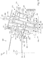
- figure 1 1 is a schematic plan view of a filling system 100 for filling a filling product into containers to be filled and for subsequently sealing the filled containers with a container closure.
- the filling system 100 comprises a filler 300 in a rotary design and a sealer 200 in a rotary design downstream of the filler 300 in the conveying direction 101 of the containers then filled and to be sealed, as well as an infeed starwheel 110 upstream of the filler 300 in the conveying direction 100, from which the containers to be filled to the filler 300 to be transferred. Furthermore, an outfeed conveyor 120 is provided, to which filled and closed containers are transferred from the sealer 200 and are removed by means of the outfeed conveyor 120 .
- the filler 300 comprises a filler carousel 304 which can be rotated relative to a preferably vertically oriented central axis of rotation 306 and on the circumference of which a plurality of filling devices 310 for filling a container with a filling product, in this case a beverage, are arranged at regular intervals from one another.
- a filler carousel 304 which can be rotated relative to a preferably vertically oriented central axis of rotation 306 and on the circumference of which a plurality of filling devices 310 for filling a container with a filling product, in this case a beverage, are arranged at regular intervals from one another.
- the axis of rotation 306 can also be angled relative to the vertical, preferably at an angle of between 0° and 15°.
- Each filling device 310 is assigned a container holder (not shown here) which is arranged underneath it as viewed in the direction of gravity and in which the container to be filled is held for filling and positioned with respect to the filling device 310 .
- the filler 300 includes a transfer section 301 of the available processing angle, in which containers to be filled are successively transferred from the infeed star wheel 110 to the container holders.
- a filling section 302 of the available processing angle in which the containers to be filled are filled by the respective filling device 310 , is located downstream of the transfer section 301 in the conveying direction 101 .
- a transfer section 303 of the available processing angle is provided, in which filled containers are transferred to the closer 200 .
- the capper 200 comprises a capper carousel 201, which can be rotated relative to a central axis of rotation 202, and on the circumference of which a plurality of capping devices 210 are regularly spaced apart from one another for capping a filled product to be capped Containers with a container closure, in this case a rotary closure, a roll-on closure or a push-on closure, are arranged.
- a container closure in this case a rotary closure, a roll-on closure or a push-on closure
- Each closing device 210 is assigned a container receptacle (not shown here), in which a filled container is held during transport through the closing device 200.
- the container receptacles of the capper 200 and/or the container holders of the filler 300 can, for example, comprise a passive clamp and/or a spike plate and/or have an active clamp that can be actively opened and closed.
- the container receptacles can be designed for neck handling, ie holding the container to be held by a neck area, and/or for base handling, ie for holding the container to be held by its bottom and/or stomach area.
- the capper 200 includes a transfer section 204 of the available processing angle, in which filled containers to be capped are successively transferred from the filler 300 to the container receptacles of the capper 200 .
- Downstream of the transfer section 204 in the conveying direction 101 is a treatment section 205 in which the containers are provided with a container closure by the respective closure device 210 .
- the treatment section 205 is followed by a transfer section 206 in which filled and closed containers are transferred to the outfeed conveyor 120 .
- a picking section 207 is provided between the transfer section 206 and the receiving section 204, in which the closing devices 210 each receive a container closure supplied from a closure supply.
- the filler 300 and the capper 200 are arranged at a specified distance from one another, so that a partial circle 307 of the filler 300, on which the containers to be filled are transported with their central axis or longitudinal axis, and a partial circle 208 of the closer 200, on which Containers are transported with their central axis or longitudinal axis touch or affect. Accordingly, the filled containers are directly transferred from the filler 300 to the closer 200 without any transfer devices such as transfer stars or transfer stars being provided between the filler 300 and the closer 200 .
- the predetermined distance mentioned relates to a distance extending along a horizontal connection direction 130 which extends between the axis of rotation 306 of the filler and a vertically oriented central axis 227 of the capper 200 .
- the specified specified distance therefore corresponds to a distance between the axis of rotation 306 and the vertical central axis 227.
- the division of the closing carousel 201 preferably corresponds to the division of the filler carousel 304.
- “Division” is understood to mean the distance between two adjacent container holders or container receptacles in the circumferential direction with respect to the respective axis of rotation 306, 202.
- the axis of rotation 202 of the closing carousel 201 and correspondingly the closing carousel 201 is inclined in relation to the vertical, thus the vertical center axis 227 extending in the gravitational direction, in the present case by a predetermined angle of inclination ⁇ .
- the capping carousel 201 is inclined with respect to the vertical axis of rotation 306 of the filler 300 .
- the axis of rotation 202 of the closer 200 is oriented in such a way that the upper side of the closer carousel 201 is inclined essentially away from the filler 300 or points away from it.
- the axis of rotation 202 of the closer 200 is preferably oriented in such a way that the angle of inclination ⁇ has a vertical angle component ⁇ S, which includes the vertical center axis 227 with a projection of the axis of rotation 202 of the closer 200 onto a plane ⁇ oriented perpendicular to the connection direction 130, and an angle component ⁇ P , which includes the vertical center axis 227 with a projection of the axis of rotation 202 of the closer 200 onto a plane formed by the connection direction 130 and the center axis 227 .
- ⁇ S which includes the vertical center axis 227 with a projection of the axis of rotation 202 of the closer 200 onto a plane ⁇ oriented perpendicular to the connection direction 130
- an angle component ⁇ P which includes the vertical center axis 227 with a projection of the axis of rotation 202 of the closer 200 onto a plane formed by the connection direction 130 and the center axis 227 .
- the axis of rotation 202 of the capper 200 is oriented in such a way that the top of the capper carousel 201 is inclined in a direction which is tangential to the conveying direction 101 at the transfer point 209 of the containers from the filler 300 to the capper 200, the transfer point 209 corresponds to an intersection of the pitch circle 208 and the connection direction 130.
- the angle of inclination ⁇ is 15°, but it can optionally also have a different amount; the angle of inclination is preferably 0°-30°, particularly preferably 1°-20°.
- the vertical angular component ⁇ S is presently 1.5°, but it can optionally also have a different amount, preferably in a range from 0°-10°, particularly preferably from 0°-3° and very particularly preferably from 1°-3° .
- the parallel angular component ⁇ P is presently 15°, but it can optionally also have a different amount, preferably in a range from 0°-30°, particularly preferably from 0°-20° and very particularly preferably from 1°-20°.
- the closing devices 210 Due to the inclination of the closing carousel 201 away from the filler 300, the closing devices 210, which are arranged in the middle to upper area of the closing carousel 201, are pivoted away from the filler 300 in the transfer area 204. Thus, the closing devices 210 are at least partially pivoted out of a collision area 140 with respect to the components of the filler 300, in particular the filling devices 310.
- the collision area 140 is in figure 1 indicated by the intersection of the collision diameter 240 of the closing carousel 201 indicated by dashed lines with the collision diameter 330 of the filler carousel 304 indicated by dashed lines.
- the collision diameters 240, 330 each correspond to a partial circle, which indicates the maximum radial extension of the filler carousel 304 or the capper carousel 201.
- the closing devices 210 are at least partially inwardly pivotable in relation to the axis of rotation 202 of the closing device 200, at least in the transfer area 204.
- the closing devices 210 are preferably pivoted inwards in such a way that they are always arranged completely outside of the collision area 140 .
- a dropper device 250 for introducing nitrogen into the respective container openings is arranged in the conveying direction 101 at the rear area of the takeover section 204, in order in this way to displace atmospheric oxygen from the top area of the filled container and/or to provide overpressure in the container after sealing to provide sealed container ready to achieve in this way a stabilization of the container due to an increased internal pressure.
- figure 2 shows a schematic side sectional view through the filling system 100 figure 1 .
- the closing devices 210 have an upper part 211 which is connected to the closing carousel 201 and an upper part which is arranged on the upper part 211 such that it can be pivoted in relation to the upper part 211 Have base 212.
- the lower part 212 is connected to the upper part 211 by means of a joint 213 , the joint 213 providing a pivot axis 214 oriented perpendicular to the axis of rotation 202 and perpendicular to the radial direction with respect to the axis of rotation 202 .
- the lower part 212 of the in figure 2 Closing device 210 shown on the left is pivoted in relation to the axis of rotation 202 by a predetermined angle ⁇ in the direction of the axis of rotation 202 of the closing device 200 .
- This swiveling of the lower parts 212 of the closing devices 210 radially inward has the effect that the lower parts 212 in the transfer section 204 move out of the collision area 140 (see figure 1 ) are pivoted and there is no collision with the filling devices 310.
- the angle ⁇ can have the same amount as the angle of inclination ⁇ . However, it can also be chosen differently, as long as freedom from collision with the filling devices 310 is guaranteed.
- a guide 215 is provided, which comprises a guide rail 217 that is rotationally fixed to the carrier 222 together with the closing carousel 201 and is height-adjustable and a guide element 216 of each closing device 210 that engages with it, as shown in FIG figure 2 shown on the left side of the capper 200 by way of example.
- the closing device 200 comprises a base frame 220 with a carriage 221 which can be moved towards and away from the filler 300 in the direction of the connection direction 130 via a linear bearing indicated by the reference number 223 .
- the distance between the closing carousel 201 and the filler 300 can be adjusted via the linear bearing 223 .
- the capper 200 also includes a carrier 222 which is arranged on the carriage 221 so as to be pivotable about a horizontal pivot axis 228 by means of a pivot bearing 224 .
- the angle of inclination ⁇ can be adjusted by the pivot bearing 224 .
- the capper carousel 201 and a guide rail 236 described in more detail below are arranged so that they can be adjusted in height relative to the carrier 222 by means of a height adjustment device 225 in the direction of the axis of rotation 202 of the capper 200 .
- the sealer 200 may further include an azimuth bearing 226 indicated by the reference numeral 226 for adjusting an angular position of the carrier 222 about the vertical central axis 227 relative to the connection direction 130 .
- the capper comprises a second pivot bearing, which preferably has a perpendicular to the pivot axis 228 of the (first) pivot bearing 224 oriented horizontal (second) pivot axis.
- the horizontal pivot axis 228 is preferably oriented perpendicularly to the connection sight 130 .
- a locking unit for locking pivot bearing 224 and/or a locking unit, not shown here, for locking linear bearing 223, and/or a locking unit, not shown here, for locking height adjustment 225, and/or a locking unit, not shown here, for locking azimuth bearing 226 or the second pivot bearing provided.
- pivot bearing 224 and/or linear bearing 223 and/or height adjustment 225 and/or azimuth bearing 226 or the second pivot bearing can each have a drive unit (not shown here), preferably a motorized drive unit, preferably comprising a spindle drive, and/or a include a manually operable drive unit, preferably comprising a spindle, for adjusting the current position.
- a drive unit not shown here
- a motorized drive unit preferably comprising a spindle drive
- a manually operable drive unit preferably comprising a spindle
- a transfer of a container 400 from the filler 300 to the closer 200 can preferably be continuously adjusted, preferably by a corresponding adjustment of the angle of inclination ⁇ via the pivot bearing 224, the height position of the capper carousel 201 or the upper part of the capper 200 via the height adjustment 225 and/or the distance or the displacement of the capper 200 via the linear bearing 223.
- the bottling system 100 and its components can accordingly be adjusted when processing is changed from containers of a first type or a first size to the processing of containers of a different type or a different size to the position specifications of the closer 200 resulting from the respective container, its type and size with regard to the filler 300 and/or with regard to an optimal treatment of the containers, such as a centrifugal force-optimized alignment of the containers during transport through the filler 300 and/or the closer 200.
- the filling system 100 is particularly variable.
- the capper carousel 201 is pivoted away from the filler by the predetermined angle of inclination ⁇ relative to the vertical or relative to the vertical central axis 227 .
- the container holder 320 is arranged pivotably on the filler carousel 304 .
- the container holder 304 has a clamp 321 for holding a container 400 in its neck region 402, which is arranged on the filler carousel 304 so that it can pivot via a joint 320 about a horizontal pivot axis 326 oriented perpendicularly to the radial direction with respect to the axis of rotation 306 of the filler 300.
- the container holder 320 is guided by means of a guide 323 in order to specify the position of the clamp 321 .
- a guide element 324 which is connected to the clamp 321 and is optionally designed as a guide roller, engages with a guide rail 325 arranged on the base frame 305 of the filler 300.
- the guide 323 for setting the position of the container holder 320 can also comprise at least one of a servomotor, hydraulic cylinder, pneumatic cylinder, magnetically operated unit and/or electrically operated unit for specifying the position of the container holder 320 (not shown here).
- the container holders 320 or their clamps 321 are preferably oriented essentially horizontally in the transfer area 301 in a receiving position.
- the container holders 320 or their clamps 321 in the transfer region 301 are preferably oriented in such a way that the central axis or longitudinal axis 405 of the containers 400 received by the clamps 321 is transferred vertically, i.e. parallel to the acceleration due to gravity and thus also parallel to the axis of rotation 306 of the filler 300 will.
- the container holder 320 or its clamp 321 can be pivoted upwards via the joint 222 so that the container 400 held in the clamp 321 pivots radially outward with its bottom 404 with respect to the axis of rotation 306 . This makes it possible to reduce or even completely eliminate a moment acting between container 400 and clamp 321 due to centrifugal force.
- the liquid level of the filling product and/or nitrogen that has dripped into the container opening 401 is oriented obliquely to the container opening 401 due to centrifugal force in such a way that it leads to a Filling product spilling over and/or nitrogen escaping from the container opening 401.
- the deflection of the container 400 can be predetermined by the guide 323 in a cam-controlled manner, so that the containers 400 are held in the intended orientation even if they are underfilled, overfilled or in the event of start-up processes.
- the guide rail 325 can comprise a complete circumferential curve or one or more curve segments.
- each container holder 320 can be assigned its own drive. This has the advantage of being able to adapt the container holder 320 individually to the filling process. In this way, particularly when filler 300 starts up or stops, an angular position of container holder 320 can be specified individually in order to determine, for example, depending on the rotational speed of filler carousel 304, the orientation of containers 400 with regard to any deflection of the containers caused by centrifugal force and/or with regard to a jet deflection caused by centrifugal force of the filling device 310 into the container 400 discharged filling product jet.
- the container holder 320 can be designed to be freely pivotable at least over a section of the filling section 302 in such a way that the clamp 321 undergoes pivoting due to centrifugal force.
- the containers 400 are pivoted from the horizontal during filling by pivoting the container holders 320, with a filling valve of the filling device 310 also being arranged at an angle or a base piece of the filling valve having a correspondingly inclined position contact surface.
- the containers 400 are pivoted radially inwards with their bottom 404 , thus pivoting with their bottom 404 in the direction of the axis of rotation 306 .
- the containers 400 are held in the transfer area 303 with respect to their longitudinal axis 405 parallel to the orientation of the container receptacles 230 of the capping carousel 201.
- each container receptacle 230 in the transfer section 204 is oriented perpendicularly to the axis of rotation 202 of the closer 200 .
- the container receptacle 230 in the transfer section 204 is inclined by the angle of inclination ⁇ to the direction of gravity or the vertical, and therefore to the vertical central axis 227 .
- the containers 400 are oriented with their longitudinal axis 405 essentially parallel to the axis of rotation 202 .
- the container receptacles 230 also have an orientation perpendicular to the axis of rotation 202 of the closure device 200 in the following treatment section 205 .
- the containers 400 are therefore oriented with their longitudinal axis 405 essentially parallel to the axis of rotation 202 of the closer 200, so that the closing device 210, which is arranged in the direction of the axis of rotation 202 of the closer 200, in each case above the container receptacle 230 and therefore above the container 400, is parallel to the axis of rotation 202 of the capper 200 oriented base 212 as in figure 2 shown on the right side of the capper 200, can apply a container cap (not shown) to the container opening 401 by lowering controlled via the guide 215.
- the container receptacles 230 in the treatment section 205 can also have an orientation that deviates from the above-described vertical orientation to the axis of rotation 202 of the closer 200, so that the containers 400 can have an orientation that is parallel to the axis of rotation 202 of the Capper 200 have different orientation.
- the closure devices 210 then also have this orientation, which deviates from the parallel orientation to the axis of rotation 202 of the closure device 200 .
- the guide 234 can also be arranged in the area of the upper side of the sealer 200 and hung down to the container receptacle 230 instead of being arranged in a lower area of the upper part of the sealer 200 .
- the leadership can be 234 be arranged radially inside the guide 215 and preferably be connected to the container receptacle 230 via a linkage.
- the container receptacles 230 are pivoted outwards from their orientation perpendicular to the axis of rotation 202 of the capper 200 by the angle of inclination ⁇ into an orientation perpendicular to the vertical, so that the longitudinal axis 405 of the containers 400 is oriented parallel to the vertical .
- the containers 400 can be transferred flatly with their bottom 404 onto the linear outfeed belt 120 without an unstable transfer and conveyance of the containers 400 occurring due to an abrupt change in inclination of the containers 400 occurring during the transfer.
- the container receptacles 230 in the transfer section 206 can be pivoted radially inwards out of the horizontal orientation assumed for the transfer to the conveyor belt 120 when the container 400 being held is transferred to the outfeed conveyor 120 as soon as the bottom 404 of the container 400 to be transferred comes into contact with the conveyor belt 120 has come, for example in the in figure 2 orientation shown on the left on the capper 200 perpendicular to the axis of rotation 202 of the capper 200 in order to facilitate release of the held container 400 to the outfeed belt 120.
- any spike plate provided on the container receptacle 230 can be disengaged from the container 400 placed on the conveyor belt 120 or from a carrying ring of the container 400 (not shown here).
- outfeed conveyor 120 can be configured to be vertically adjustable, i.e. adjustable parallel to the direction of gravity, and/or horizontally displaceable, i.e. adjustable perpendicular to the direction of gravity, in order to be able to follow a change in the orientation and position of capper 200 and always in transfer section 206 to be arranged in a predetermined position to the container receptacles 230.
- the axis of rotation 306 of the filler 300 can also be designed to be inclined relative to the vertical. This may be advantageous with regard to an improved transfer of filled containers 400 to the sealer 200.
- the inclined position of the axis of rotation 306 with respect to the vertical can be realized by a mechanism corresponding to that of the capper 200, for example comprising a correspondingly designed pivot bearing.
- the oblique position of the closer 200 with respect to its axis of rotation 202 and/or the oblique position of the filler 300 with respect to its axis of rotation 306 can alternatively be realized by arranging feet of different lengths on the closer 200 or filler 300.
- FIG. 12 schematically shows a detailed side view of the filling system 100 figure 2 .
- the container receptacle 230 in the transfer section 204 is deflected outwards by a predetermined deflection angle ⁇ relative to the axis of rotation 202 of the capper 200 .
- the bottom 404 of the container 400 is pivoted radially outwards from the axis of rotation 202 of the closer 200 in comparison to its position when the container 400 is oriented parallel to the axis of rotation 202 of the closer 200 .
- the longitudinal axis 405 of the container 400 thus encloses an angle with the vertical which corresponds to the sum of the angle of inclination ⁇ and the angle of deflection ⁇ .
- This embodiment can be particularly advantageous when the diameters of the pitch circles 208, 307 differ greatly and/or at a particularly high conveying speed.
- the additional deflection of the container 400 during the transfer can be used to prevent the filling product and/or nitrogen above it from spilling out of the container 400 at high conveying speeds due to a change in centrifugal force acting on the liquid filling product in the container 400.
- figure 4 1 is a further detailed side view of the filling system 100 schematically figure 2 shown, with the container receptacle 230 in the transfer section 204 being deflected inwards relative to the axis of rotation 202 by a predetermined deflection angle ⁇ with respect to an orientation perpendicular to the axis of rotation 202 .
- the bottom 404 of the container is pivoted radially inwards from the axis of rotation 202 in comparison to its position when the container 400 is oriented parallel to the axis of rotation 202 .
- the longitudinal axis 405 of the container 400 therefore encloses an angle ⁇ with the vertical, which angle corresponds to the amount of a difference between the angle of inclination ⁇ and the angle of deflection ⁇ .
- figure 5 1 is a further detailed side view of the filling system 100 schematically figure 2 shown, with the container receptacle 230 in the transfer section 204 being deflected inwards relative to the axis of rotation 202 of the capper 200 by a deflection angle ⁇ with the amount of the angle of inclination ⁇ . Accordingly, compared to its position when the container 400 is oriented parallel to the axis of rotation 202 of the closer 200, the base 404 is pivoted radially inwards from the axis of rotation 202 of the closer 200 into an orientation perpendicular to the vertical, the container axis 405 is therefore essentially parallel to the vertical oriented.
- the articulated connection of the container holder 320 to the filler carousel 304 can be dispensed with.
- the clamp 321 can also be arranged on the filler carousel 304 with a fixed orientation perpendicular to the axis of rotation 306 of the filler 300 and the joint 322 and the guide 323 can be dispensed with.
- FIG 6 1 is a further detailed side view of the filling system 100 schematically figure 2 shown, in which case the container receptacle 230 is rigidly attached to the closure carousel 201. Consequently, the orientation of the clamp 231 and the support 232 is always perpendicular to the axis of rotation 202.
- the container receptacle 320 must therefore be deflected downwards in the transfer section 303 by the angle of inclination ⁇ so that the longitudinal axis 405 is oriented essentially parallel to the axis of rotation 202 and the container receptacle 230 den to be transferred container 400 can properly accommodate.
- figure 7 1 is a further detailed side view of the filling system 100 schematically figure 2 shown, with both the container holder 320 being arranged rigidly on the filler carousel 304 and the container receptacle 230 being rigidly arranged on the closing carousel 201 in this embodiment.
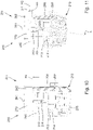
- figure 8 shows a schematic side sectional view through the closing device 210 for closing a container 400 with a container closure, as for example in the closure 200 according to FIG figures 1 and 2 can be used.
- Closing device 210 comprises a bracket 262 and a lifting cylinder 261 that can be displaced in a longitudinal direction 261 relative to bracket 262.
- a height position H of lifting cylinder 260 relative to bracket 262 is determined here by guide element 235, which is arranged on lifting cylinder 260 and is in the form of a guide roller , given in cooperation with the guide rail 236.
- the holder 262 and the lifting cylinder 260 together form the upper part 211 of the closing device 210 .
- the lower part 212 is pivotably mounted on the lifting cylinder 260 via the joint 213 on the end side of the upper part 211 facing the container receptacle 230, correspondingly on the lower end side of the lifting cylinder 260.
- the pivot axis formed by the joint 213 is aligned perpendicular to the longitudinal direction 261 and perpendicular to the radial direction with respect to the longitudinal direction 261 .
- a pretensioning unit 268 for pretensioning the lower part 212 in a predetermined position relative to the lifting cylinder 260 is provided between the lifting cylinder 260 and the lower part 212 .
- the pretensioning unit 268 is designed in the present case in the form of a spring return unit which, via spring force, moves the lower part 212 into the in figure 8 shown position, in which the base extends in the longitudinal direction 261 biases.
- a gear wheel 264 arranged on the lower part is in engagement with a spur gear 265 of a drive unit 263 arranged on the holder 262 for driving the lower part, in this case for specifying a rotational movement about the longitudinal direction 261 for a closure receptacle 266 arranged at the free lower end of the lower part 212 .
- a flexible sealing element configured here as a trapezoidal bellows 280, is arranged on the lower part 212, which extends from the lower part 212 to an annular seal 281, by means of which a seal can be provided to a treatment room wall, for example a wall of a clean room.
- the cross section of the seal 281 is optionally oval.
- the seal 281 is designed in such a way that the lower part 212 can be pivoted via the joint 123 at least between the in figure 8 shown position of the lower part 212 aligned along the longitudinal direction 261 and the position of the lower part 212 pivoted by the angle ⁇ , as in FIG figure 9 shown, without the base 212 colliding with the seal 281.
- the bellows 280 preferably has a substantially oval, elliptical or slot-like cross section and tapers from the seal 281 in the direction of the connection of the bellows 280 to the lower part 212.
- the bellows 280 comprises an elastomer, preferably a cleaning medium against the filling product and/or sterilization medium, particularly preferably against hot water, steam, detergents, caustic soda and/or potassium hydroxide, silicone oils and silicone fats, and/or at least some polar solvents, elastomer resistant, particularly preferably EPDM or silicone.
- the seal 281 comprises a rotary bearing, preferably a plain bearing or a roller bearing, preferably a ball bearing, with the bellows 280 being designed such that during a rotary movement of the lower part 212 a friction resulting from the rotary movement is transmitted in the rotary bearing and the friction during the rotation or changes to be able to absorb the moments of inertia arising from the rotational movement without being twisted in the direction of the rotational movement.
- the bellows preferably points towards this a predetermined wall thickness, which is tailored to the mechanical properties of the material and the dimensions, in particular the length and the radial extent, of the bellows 280.
- the bellows 280 is made by vacuum forming. Alternatively, other manufacturing processes can also be used.
- the bellows 280 is designed to be able to compensate for a maximum possible stroke of the lower part 212 in relation to the connection of the seal 281 to the treatment room wall.
- the closing device 210 also includes an ejection unit 270 for ejecting a container closure held in the closure receptacle 266 .
- an ejection unit 270 for ejecting a container closure held in the closure receptacle 266 .
- a head pressure on a container closure can be provided or increased by means of the ejector during the application of the container closure to the container.
- the ejector 270 has a control unit 271 for controlling a position of the ejector in the longitudinal direction 261 .
- Control unit 271 preferably includes a servo motor, a stepper motor, a pneumatic cylinder and/or a hydraulic cylinder for actively controlling ejector 270.
- the control unit 271 is preferably set up to provide an ejection of a container closure located in the closure receptacle 266 independently of the angular position of the closure device 210 with respect to the axis of rotation 202 . Consequently, the control unit 271 is set up to be able to carry out an ejection at any point over the circumference of the closing carousel 201 .
- the control unit 271 can preferably be or is connected to a central controller (not shown) of the closer 200 .
- the control unit 271 is preferably set up to trigger ejection only when a container closure is present in the closure receptacle 266, preferably downstream of the treatment section 205 and/or the transfer section 206 as seen in the conveying direction, but preferably upstream of the picking section.
- control unit is optionally set up to trigger an ejection if the control unit 271 receives information that there is no container 400 in the container receptacle 230 assigned to the closing unit 210 or was in the treatment section 205, and/or if the control unit 271 receives information that at one through the Closing device 210 executed, predetermined closing process, a predetermined torque was not reached, or receives information that no torque was transmitted via the recorded container closure during the course of the closing process.
- the ejector 270 comprises an upper contact element 272 which is arranged in the lifting cylinder 260 and which can be moved in the longitudinal direction 261 relative to the lifting cylinder 260 via the control unit 271 .
- the ejector 270 also includes a lower ejector rod 273 which can be displaced in the lower part 212 in its longitudinal direction 261 and which in the present case is pretensioned by means of a pretensioning element 275 in a position which is pretensioned in the direction of the lifting cylinder 260 .
- the lifting cylinder 260 has a first height position H1, in which a stop pin 268 arranged on the holder 262 touches a stop element 269 of the lower part 212, essentially without exerting a force on the stop element 269.
- FIG. 12 schematically shows a further sectional view of the closing device 210 figure 8 , in which case the lower part 212 is pivoted about the pivot axis 214 by the angle ⁇ from the longitudinal direction 261.
- the lifting cylinder 260 is lifted via the guide element 216 to a height position H2 which is higher by a predetermined height difference ⁇ H than the first height position H1 according to figure 8 , in which the stop pin 268 and the stop element 269 touch.
- the stop bolt 268 Since the stop bolt 268 is fixedly arranged on the holder 262, it accordingly has a fixed height level. By raising the lifting cylinder 260 beyond the first height position H1, the stop bolt 268 presses on the stop element 269 and prevents the stop element 269 from being able to follow the movement of the lifting cylinder 260. Accordingly, the lower part pivots about the pivot axis 214 against the bias of the bias unit 267.
- the height difference ⁇ H is specified in such a way that the lower part 212 is deflected by the angle ⁇ .
- the gear wheel 264 Due to the deflection of the lower part 212 by the angle ⁇ , the gear wheel 264, according to this embodiment, disengages from the spur gear 265.
- the spur gear 265 has a tooth width such that the spur gear 265 and the gear wheel 264 can be displaced axially relative to one another without that the teeth of gear 264 and spur gear 265 disengage.
- the closing device 210 can also be designed in such a way that the gear 264 and the spur gear 265 in the position deflected by the angle ⁇ from the longitudinal direction 261 according to figure 9 do not disengage, but remain engaged.
- the lower ejector rod 273 and the upper contact element 272 are disengaged by the deflection of the lower part 212 by the angle ⁇ .
- the lower ejector rod 273 and the upper contact member 272 may remain permanently connected, preferably via a joint, more preferably a ball joint or universal joint (not shown).
- FIGS. 10 and 11 are schematic detail views of the figures 8 and 9 in the area of the connection between lifting cylinder 260 and lower part 212.
- the upper contact element 272 is in contact with the end face of the lower ejector rod 273, the end face of the ejector rod 273 being designed as a rounded portion 274. This can prevent the lower ejector rod 273 and the upper contact element 272 from jamming or jamming when the lower part 212 is pivoted relative to the lifting cylinder 260 about the pivot axis 214 .
- the height position H1 of the lift cylinder 260 is in figure 10 indicated again on the side of the stop bolt 268.
- the lifting cylinder 260 is raised by the height difference ⁇ H to the second height position H2.
- stop bolt 268 prevents stop element 269, which is arranged on the opposite side of joint 213 with respect to central longitudinal direction 261, and therefore the central longitudinal axis of lifting cylinder 260, from being able to follow the lifting of lifting cylinder 260 .
- the lower part 212 experiences the deflection about the pivot axis 214 until the lower part 212 is kept pivoted by the angle ⁇ when the lifting cylinder 260 assumes the second vertical position H2.
- all individual features that are presented in the exemplary embodiments can be combined with one another and/or exchanged without departing from the scope of the invention.
Landscapes
- Engineering & Computer Science (AREA)
- Mechanical Engineering (AREA)
- Filling Of Jars Or Cans And Processes For Cleaning And Sealing Jars (AREA)
Applications Claiming Priority (1)
| Application Number | Priority Date | Filing Date | Title |
|---|---|---|---|
| DE102021113361.0A DE102021113361A1 (de) | 2021-05-21 | 2021-05-21 | Abfüllanlage zum Abfüllen eines Füllprodukts |
Publications (1)
| Publication Number | Publication Date |
|---|---|
| EP4091983A1 true EP4091983A1 (fr) | 2022-11-23 |
Family
ID=81841939
Family Applications (1)
| Application Number | Title | Priority Date | Filing Date |
|---|---|---|---|
| EP22174797.5A Pending EP4091983A1 (fr) | 2021-05-21 | 2022-05-23 | Installation de remplissage permettant de remplir un produit de remplissage |
Country Status (3)
| Country | Link |
|---|---|
| EP (1) | EP4091983A1 (fr) |
| CN (1) | CN218507546U (fr) |
| DE (1) | DE102021113361A1 (fr) |
Citations (3)
| Publication number | Priority date | Publication date | Assignee | Title |
|---|---|---|---|---|
| WO2010133648A1 (fr) * | 2009-05-20 | 2010-11-25 | Serac Group | Procede de transport de recipients par support partiel de ceux-ci et installation mettant en oeuvre ce procede |
| WO2017174772A1 (fr) * | 2016-04-07 | 2017-10-12 | Krones Ag | Dispositif de traitement de récipients et installation de remplissage de boissons |
| EP3521238A2 (fr) * | 2017-12-14 | 2019-08-07 | Krones Ag | Dispositif de transport d'un récipient |
-
2021
- 2021-05-21 DE DE102021113361.0A patent/DE102021113361A1/de active Pending
-
2022
- 2022-05-20 CN CN202221213420.4U patent/CN218507546U/zh active Active
- 2022-05-23 EP EP22174797.5A patent/EP4091983A1/fr active Pending
Patent Citations (3)
| Publication number | Priority date | Publication date | Assignee | Title |
|---|---|---|---|---|
| WO2010133648A1 (fr) * | 2009-05-20 | 2010-11-25 | Serac Group | Procede de transport de recipients par support partiel de ceux-ci et installation mettant en oeuvre ce procede |
| WO2017174772A1 (fr) * | 2016-04-07 | 2017-10-12 | Krones Ag | Dispositif de traitement de récipients et installation de remplissage de boissons |
| EP3521238A2 (fr) * | 2017-12-14 | 2019-08-07 | Krones Ag | Dispositif de transport d'un récipient |
Also Published As
| Publication number | Publication date |
|---|---|
| CN218507546U (zh) | 2023-02-21 |
| DE102021113361A1 (de) | 2022-11-24 |
Similar Documents
| Publication | Publication Date | Title |
|---|---|---|
| EP4091984A1 (fr) | Dispositif de fermeture et appareil de fermeture permettant de fermer un récipient | |
| EP2684805B1 (fr) | Dispositif pour guider des récipients | |
| EP3440007B1 (fr) | Système de remplissage de boissons pour le remplissage de récipients | |
| DE2722254C3 (de) | Flaschenverschließmaschine umlaufender Bauart | |
| EP1520833A1 (fr) | Machine de traitement de récipients | |
| EP2653435B1 (fr) | Dispositif destiné à fermer des récipients | |
| DE4208441A1 (de) | Verfahren und vorrichtung zum verschliessen von flaschen | |
| EP2697150B1 (fr) | Procédé et machine de remplissage pour le remplissage à jet libre de bouteilles ou de contenants similaires | |
| WO2013026523A2 (fr) | Dispositif de remplissage et procédé de commande d'un dispositif de remplissage | |
| EP3924292B1 (fr) | Dispositif de traitement des récipients avec élément de transport | |
| DE102021113366A1 (de) | Füller, Verschließer und Abfüllanlage | |
| EP4091983A1 (fr) | Installation de remplissage permettant de remplir un produit de remplissage | |
| EP3386870B1 (fr) | Machine de traitement des recipients | |
| DE102021113362A1 (de) | Verschließvorrichtung und Verschließer zum Verschließen eines Behälters | |
| EP4008683B1 (fr) | Dispositif de manutention d'au moins un récipient | |
| EP2285725B1 (fr) | Dispositif pour fermer des récipients avec un bouchon à visser | |
| EP4011819B1 (fr) | Dispositif et procédé de fermeture d'un récipient au moyen d'une fermeture de récipient | |
| EP4161861B1 (fr) | Dispositif pour la fermeture des récipients | |
| EP4169871B1 (fr) | Dispositif d'alimentation de bouchons à un dispositif de fermeture dans une installation de remplissage de boissons | |
| DE102005042275A1 (de) | Linearverschließer | |
| EP3741722B1 (fr) | Agencement de fermeture permettant de fermer un récipient à l'aide d'une fermeture pour récipient | |
| DE4439376C2 (de) | Einrichtung zum Entfernen von Kronenkorken | |
| EP4375229A1 (fr) | Dispositif de fermeture pour fermer des récipients | |
| DE102022127240A1 (de) | Behältertransportvorrichtung mit einer Führungsvorrichtung und Verfahren zum Transportieren von Behältern | |
| DE102015110765A1 (de) | Vorrichtung zum Transport eines Behälters |
Legal Events
| Date | Code | Title | Description |
|---|---|---|---|
| PUAI | Public reference made under article 153(3) epc to a published international application that has entered the european phase |
Free format text: ORIGINAL CODE: 0009012 |
|
| STAA | Information on the status of an ep patent application or granted ep patent |
Free format text: STATUS: THE APPLICATION HAS BEEN PUBLISHED |
|
| AK | Designated contracting states |
Kind code of ref document: A1 Designated state(s): AL AT BE BG CH CY CZ DE DK EE ES FI FR GB GR HR HU IE IS IT LI LT LU LV MC MK MT NL NO PL PT RO RS SE SI SK SM TR |
|
| STAA | Information on the status of an ep patent application or granted ep patent |
Free format text: STATUS: REQUEST FOR EXAMINATION WAS MADE |
|
| 17P | Request for examination filed |
Effective date: 20230418 |
|
| RBV | Designated contracting states (corrected) |
Designated state(s): AL AT BE BG CH CY CZ DE DK EE ES FI FR GB GR HR HU IE IS IT LI LT LU LV MC MK MT NL NO PL PT RO RS SE SI SK SM TR |