EP4092481B1 - Élément de commande d'itinéraire lumineux et dispositif d'affichage le comprenant - Google Patents
Élément de commande d'itinéraire lumineux et dispositif d'affichage le comprenant Download PDFInfo
- Publication number
- EP4092481B1 EP4092481B1 EP21741089.3A EP21741089A EP4092481B1 EP 4092481 B1 EP4092481 B1 EP 4092481B1 EP 21741089 A EP21741089 A EP 21741089A EP 4092481 B1 EP4092481 B1 EP 4092481B1
- Authority
- EP
- European Patent Office
- Prior art keywords
- partition wall
- light
- wall part
- control member
- electrode
- Prior art date
- Legal status (The legal status is an assumption and is not a legal conclusion. Google has not performed a legal analysis and makes no representation as to the accuracy of the status listed.)
- Active
Links
Images




Classifications
-
- G—PHYSICS
- G02—OPTICS
- G02F—OPTICAL DEVICES OR ARRANGEMENTS FOR THE CONTROL OF LIGHT BY MODIFICATION OF THE OPTICAL PROPERTIES OF THE MEDIA OF THE ELEMENTS INVOLVED THEREIN; NON-LINEAR OPTICS; FREQUENCY-CHANGING OF LIGHT; OPTICAL LOGIC ELEMENTS; OPTICAL ANALOGUE/DIGITAL CONVERTERS
- G02F1/00—Devices or arrangements for the control of the intensity, colour, phase, polarisation or direction of light arriving from an independent light source, e.g. switching, gating or modulating; Non-linear optics
- G02F1/01—Devices or arrangements for the control of the intensity, colour, phase, polarisation or direction of light arriving from an independent light source, e.g. switching, gating or modulating; Non-linear optics for the control of the intensity, phase, polarisation or colour
- G02F1/165—Devices or arrangements for the control of the intensity, colour, phase, polarisation or direction of light arriving from an independent light source, e.g. switching, gating or modulating; Non-linear optics for the control of the intensity, phase, polarisation or colour based on translational movement of particles in a fluid under the influence of an applied field
- G02F1/1675—Constructional details
- G02F1/1679—Gaskets; Spacers; Sealing of cells; Filling or closing of cells
- G02F1/1681—Gaskets; Spacers; Sealing of cells; Filling or closing of cells having two or more microcells partitioned by walls, e.g. of microcup type
-
- G—PHYSICS
- G02—OPTICS
- G02F—OPTICAL DEVICES OR ARRANGEMENTS FOR THE CONTROL OF LIGHT BY MODIFICATION OF THE OPTICAL PROPERTIES OF THE MEDIA OF THE ELEMENTS INVOLVED THEREIN; NON-LINEAR OPTICS; FREQUENCY-CHANGING OF LIGHT; OPTICAL LOGIC ELEMENTS; OPTICAL ANALOGUE/DIGITAL CONVERTERS
- G02F1/00—Devices or arrangements for the control of the intensity, colour, phase, polarisation or direction of light arriving from an independent light source, e.g. switching, gating or modulating; Non-linear optics
- G02F1/01—Devices or arrangements for the control of the intensity, colour, phase, polarisation or direction of light arriving from an independent light source, e.g. switching, gating or modulating; Non-linear optics for the control of the intensity, phase, polarisation or colour
- G02F1/13—Devices or arrangements for the control of the intensity, colour, phase, polarisation or direction of light arriving from an independent light source, e.g. switching, gating or modulating; Non-linear optics for the control of the intensity, phase, polarisation or colour based on liquid crystals, e.g. single liquid crystal display cells
- G02F1/137—Devices or arrangements for the control of the intensity, colour, phase, polarisation or direction of light arriving from an independent light source, e.g. switching, gating or modulating; Non-linear optics for the control of the intensity, phase, polarisation or colour based on liquid crystals, e.g. single liquid crystal display cells characterised by the electro-optical or magneto-optical effect, e.g. field-induced phase transition, orientation effect, guest-host interaction or dynamic scattering
-
- E—FIXED CONSTRUCTIONS
- E06—DOORS, WINDOWS, SHUTTERS, OR ROLLER BLINDS IN GENERAL; LADDERS
- E06B—FIXED OR MOVABLE CLOSURES FOR OPENINGS IN BUILDINGS, VEHICLES, FENCES OR LIKE ENCLOSURES IN GENERAL, e.g. DOORS, WINDOWS, BLINDS, GATES
- E06B9/00—Screening or protective devices for wall or similar openings, with or without operating or securing mechanisms; Closures of similar construction
- E06B9/24—Screens or other constructions affording protection against light, especially against sunshine; Similar screens for privacy or appearance; Slat blinds
-
- G—PHYSICS
- G02—OPTICS
- G02F—OPTICAL DEVICES OR ARRANGEMENTS FOR THE CONTROL OF LIGHT BY MODIFICATION OF THE OPTICAL PROPERTIES OF THE MEDIA OF THE ELEMENTS INVOLVED THEREIN; NON-LINEAR OPTICS; FREQUENCY-CHANGING OF LIGHT; OPTICAL LOGIC ELEMENTS; OPTICAL ANALOGUE/DIGITAL CONVERTERS
- G02F1/00—Devices or arrangements for the control of the intensity, colour, phase, polarisation or direction of light arriving from an independent light source, e.g. switching, gating or modulating; Non-linear optics
- G02F1/01—Devices or arrangements for the control of the intensity, colour, phase, polarisation or direction of light arriving from an independent light source, e.g. switching, gating or modulating; Non-linear optics for the control of the intensity, phase, polarisation or colour
- G02F1/165—Devices or arrangements for the control of the intensity, colour, phase, polarisation or direction of light arriving from an independent light source, e.g. switching, gating or modulating; Non-linear optics for the control of the intensity, phase, polarisation or colour based on translational movement of particles in a fluid under the influence of an applied field
- G02F1/1675—Constructional details
- G02F1/1676—Electrodes
-
- E—FIXED CONSTRUCTIONS
- E06—DOORS, WINDOWS, SHUTTERS, OR ROLLER BLINDS IN GENERAL; LADDERS
- E06B—FIXED OR MOVABLE CLOSURES FOR OPENINGS IN BUILDINGS, VEHICLES, FENCES OR LIKE ENCLOSURES IN GENERAL, e.g. DOORS, WINDOWS, BLINDS, GATES
- E06B9/00—Screening or protective devices for wall or similar openings, with or without operating or securing mechanisms; Closures of similar construction
- E06B9/24—Screens or other constructions affording protection against light, especially against sunshine; Similar screens for privacy or appearance; Slat blinds
- E06B2009/2464—Screens or other constructions affording protection against light, especially against sunshine; Similar screens for privacy or appearance; Slat blinds featuring transparency control by applying voltage, e.g. LCD, electrochromic panels
-
- E—FIXED CONSTRUCTIONS
- E06—DOORS, WINDOWS, SHUTTERS, OR ROLLER BLINDS IN GENERAL; LADDERS
- E06B—FIXED OR MOVABLE CLOSURES FOR OPENINGS IN BUILDINGS, VEHICLES, FENCES OR LIKE ENCLOSURES IN GENERAL, e.g. DOORS, WINDOWS, BLINDS, GATES
- E06B3/00—Window sashes, door leaves, or like elements for closing wall or like openings; Layout of fixed or moving closures, e.g. windows in wall or like openings; Features of rigidly-mounted outer frames relating to the mounting of wing frames
- E06B3/66—Units comprising two or more parallel glass or like panes permanently secured together
- E06B3/67—Units comprising two or more parallel glass or like panes permanently secured together characterised by additional arrangements or devices for heat or sound insulation or for controlled passage of light
- E06B3/6715—Units comprising two or more parallel glass or like panes permanently secured together characterised by additional arrangements or devices for heat or sound insulation or for controlled passage of light specially adapted for increased thermal insulation or for controlled passage of light
- E06B3/6722—Units comprising two or more parallel glass or like panes permanently secured together characterised by additional arrangements or devices for heat or sound insulation or for controlled passage of light specially adapted for increased thermal insulation or for controlled passage of light with adjustable passage of light
-
- G—PHYSICS
- G02—OPTICS
- G02F—OPTICAL DEVICES OR ARRANGEMENTS FOR THE CONTROL OF LIGHT BY MODIFICATION OF THE OPTICAL PROPERTIES OF THE MEDIA OF THE ELEMENTS INVOLVED THEREIN; NON-LINEAR OPTICS; FREQUENCY-CHANGING OF LIGHT; OPTICAL LOGIC ELEMENTS; OPTICAL ANALOGUE/DIGITAL CONVERTERS
- G02F1/00—Devices or arrangements for the control of the intensity, colour, phase, polarisation or direction of light arriving from an independent light source, e.g. switching, gating or modulating; Non-linear optics
- G02F1/01—Devices or arrangements for the control of the intensity, colour, phase, polarisation or direction of light arriving from an independent light source, e.g. switching, gating or modulating; Non-linear optics for the control of the intensity, phase, polarisation or colour
- G02F1/13—Devices or arrangements for the control of the intensity, colour, phase, polarisation or direction of light arriving from an independent light source, e.g. switching, gating or modulating; Non-linear optics for the control of the intensity, phase, polarisation or colour based on liquid crystals, e.g. single liquid crystal display cells
- G02F1/1323—Arrangements for providing a switchable viewing angle
-
- G—PHYSICS
- G02—OPTICS
- G02F—OPTICAL DEVICES OR ARRANGEMENTS FOR THE CONTROL OF LIGHT BY MODIFICATION OF THE OPTICAL PROPERTIES OF THE MEDIA OF THE ELEMENTS INVOLVED THEREIN; NON-LINEAR OPTICS; FREQUENCY-CHANGING OF LIGHT; OPTICAL LOGIC ELEMENTS; OPTICAL ANALOGUE/DIGITAL CONVERTERS
- G02F1/00—Devices or arrangements for the control of the intensity, colour, phase, polarisation or direction of light arriving from an independent light source, e.g. switching, gating or modulating; Non-linear optics
- G02F1/01—Devices or arrangements for the control of the intensity, colour, phase, polarisation or direction of light arriving from an independent light source, e.g. switching, gating or modulating; Non-linear optics for the control of the intensity, phase, polarisation or colour
- G02F1/165—Devices or arrangements for the control of the intensity, colour, phase, polarisation or direction of light arriving from an independent light source, e.g. switching, gating or modulating; Non-linear optics for the control of the intensity, phase, polarisation or colour based on translational movement of particles in a fluid under the influence of an applied field
- G02F1/1675—Constructional details
- G02F1/1677—Structural association of cells with optical devices, e.g. reflectors or illuminating devices
-
- G—PHYSICS
- G02—OPTICS
- G02F—OPTICAL DEVICES OR ARRANGEMENTS FOR THE CONTROL OF LIGHT BY MODIFICATION OF THE OPTICAL PROPERTIES OF THE MEDIA OF THE ELEMENTS INVOLVED THEREIN; NON-LINEAR OPTICS; FREQUENCY-CHANGING OF LIGHT; OPTICAL LOGIC ELEMENTS; OPTICAL ANALOGUE/DIGITAL CONVERTERS
- G02F1/00—Devices or arrangements for the control of the intensity, colour, phase, polarisation or direction of light arriving from an independent light source, e.g. switching, gating or modulating; Non-linear optics
- G02F1/01—Devices or arrangements for the control of the intensity, colour, phase, polarisation or direction of light arriving from an independent light source, e.g. switching, gating or modulating; Non-linear optics for the control of the intensity, phase, polarisation or colour
- G02F1/165—Devices or arrangements for the control of the intensity, colour, phase, polarisation or direction of light arriving from an independent light source, e.g. switching, gating or modulating; Non-linear optics for the control of the intensity, phase, polarisation or colour based on translational movement of particles in a fluid under the influence of an applied field
- G02F1/1675—Constructional details
- G02F2001/1678—Constructional details characterised by the composition or particle type
-
- G—PHYSICS
- G02—OPTICS
- G02F—OPTICAL DEVICES OR ARRANGEMENTS FOR THE CONTROL OF LIGHT BY MODIFICATION OF THE OPTICAL PROPERTIES OF THE MEDIA OF THE ELEMENTS INVOLVED THEREIN; NON-LINEAR OPTICS; FREQUENCY-CHANGING OF LIGHT; OPTICAL LOGIC ELEMENTS; OPTICAL ANALOGUE/DIGITAL CONVERTERS
- G02F2203/00—Function characteristic
- G02F2203/02—Function characteristic reflective
- G02F2203/023—Function characteristic reflective total internal reflection
Definitions
- such a light-shielding film may be a light-shielding film that can always control the viewing angle regardless of the surrounding environment or the user's environment, and switchable light-shielding film that allows the user to turn on/off the viewing angle control according to the surrounding environment or the user's environment may be distinguished.
- Such a switchable light-shielding film may be implemented by adding electrically moving particles to the pattern part and changing the pattern part into a light transmitting portion and a light blocking portion by dispersion and aggregation of the particles.
- the pattern part may be divided into a plurality of pattern part by a plurality of partition wall parts disposed between the pattern parts.
- the pattern part may be formed by forming the shape of the pattern part in a resin material using a mold, and filling the formed pattern part with a dispersion in which light conversion particles are dispersed.
- the pattern part is formed while extending from the lower part to the upper part and having an inclined surface with a larger width. Accordingly, there is a problem in that the light movement path is reduced by the width of the pattern part above the pattern part from which the light is emitted, so that the front luminance of the light route control member is reduced.
- the front luminance of the light route control member can be improved according to the increase in the movement path of the light.
- the side shielding effect may be improved.
- the inclination angle of the partition wall part and the receiving part it is possible to control an incident angle, a refraction angle, and total reflection according to a difference in refractive index between the partition wall part and the receiving part. Accordingly, even when the receiving part of the light route control member is driven to the light transmitting portion, loss of light can be reduced, so that the front luminance of the light route control member can be improved.
- the "on (over)” or “under (below)” may include not only when two elements are directly connected to each other, but also when one or more other elements are formed or disposed between two elements.
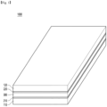
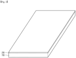
- the first substrate 110 may support the first electrode 210.
- the first substrate 110 may be rigid or flexible.
- the first substrate 110 may be transparent.
- the first substrate 110 may include a transparent substrate capable of transmitting light.
- the first substrate 110 may be a curved or bended substrate. That is, the light route control member including the first substrate 110 may also be formed to have flexible, curved, or bent characteristics. Accordingly, the light route control member according to the embodiment may be changed to various designs.
- the first substrate 110 may have a thickness of 30um to 80um.
- the first electrode 210 may contain a transparent conductive material.
- the first electrode 210 may contain a metal oxide such as indium tin oxide, indium zinc oxide, copper oxide, tin oxide, zinc oxide, titanium oxide, etc.
- the first electrode 210 may contain various metals to realize low resistance.
- the first electrode 210 may contain at least one metal of chromium (Cr), nickel (Ni), copper (Cu), aluminum (Al), silver (Ag), molybdenum (Mo). gold (Au), titanium (Ti), and alloys thereof.
- the first electrode 210 may be disposed on the entire surface of one surface of the first substrate 110.
- the first electrode 210 may be disposed as a surface electrode on one surface of the first substrate 110.
- the embodiment is not limited thereto, and the first electrode 210 may be formed of a plurality of pattern electrodes having a predetermined pattern.
- the first electrode 210 may include a plurality of conductive patterns.
- the first electrode 210 may include a plurality of mesh lines intersecting each other and a plurality of mesh openings formed by the mesh lines.
- the second substrate 120 is disposed on the first substrate 110.
- the second substrate 120 may be disposed on the first electrode 210 on the first substrate 110.
- the second substrate 120 may be a flexible substrate having flexible characteristics.
- the second electrode 220 may contain a transparent conductive material.
- the second electrode 220 may contain a metal oxide such as indium tin oxide, indium zinc oxide, copper oxide, tin oxide, zinc oxide, titanium oxide, etc.
- the second electrode 220 may be disposed on the entire surface of one surface of the second substrate 120.
- the second electrode 220 may be disposed as a surface electrode on one surface of the second substrate 120.
- the embodiment is not limited thereto, and the second electrode 220 may be formed of a plurality of pattern electrodes having a predetermined pattern.
- the second electrode 220 may include a plurality of conductive patterns.
- the second electrode 220 may include a plurality of mesh lines intersecting each other and a plurality of mesh openings formed by the mesh lines.
- the second electrode 220 contains a metal
- visibility may be improved because the second electrode 220 is not visible from the outside.
- the light transmittance is increased by the openings, so that the brightness of the light route control member according to the embodiment may be improved.
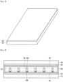
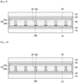
- the light conversion part 300 includes a partition wall part 310 and a receiving part 320.
- the partition wall part 310 is defined as a partition wall region that partitions the receiving part. That is, the partition wall part 310 is a partition wall region partitioning a plurality of receiving parts. And the receiving part 320 is defined as a region that changes into a light blocking part and a light transmitting part according to the application of a voltage.
- the partition wall part 310 may contain a resin material.
- the partition wall part 310 may contain a photo-curable resin material.
- the partition wall part 310 may contain a UV resin or a transparent photoresist resin.
- the partition wall part 310 may contain urethane resin or acrylic resin.
- the dispersion 320a may be a material for dispersing the light conversion particles 320b.
- the dispersion 320a may contain a transparent material.
- the dispersion 320a may contain a non-polar solvent.
- the dispersion 320a may contain a material capable of transmitting light.
- the dispersion 320a may include at least one of a halocarbonbased oil, a paraffin-based oil, and isopropyl alcohol.
- the light conversion particles 320b may be disposed to be dispersed in the dispersion 330a.
- the plurality of light conversion particles 320b may be disposed to be spaced apart from each other in the dispersion 330a.
- the surface of the light conversion particle 320b may be charged. Accordingly, according to the application of the voltage, the light conversion particles 320b may move in one direction.
- the light path member according to the embodiment may be change from the first mode to the second mode or from the second mode to the first mode by a voltage applied to the first electrode 210 and the second electrode 220.
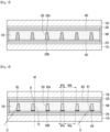
- the receiving part 320 becomes the light transmitting part in the second mode, and in the light route control member according to the embodiment, light may be transmitted through both the partition wall part 310 and the receiving part 320. That is, the viewing angle of the user viewing from the outside may be widened.
- the receiving part 320 may be electrically connected to the first electrode 210 and the second electrode 220.
- the light conversion particles 320b of the receiving part 320 are uniformly dispersed in the dispersion 330a, and light may be blocked by the light conversion particles in the receiving part 320. Accordingly, in the first mode, the receiving part 320 may be driven as the light blocking part.
- the light conversion particles 320b in a negatively charged state can be moved in the direction of the positively charged electrode among the first electrode 210 and the second electrode 220 using the dispersion 320a as a medium.
- the light conversion particles 320b may be uniformly dispersed in the dispersion 320a to drive the receiving part 30202 as the light blocking part.
- the partition wall part 310 and the receiving part 320 may have opposite shapes.
- a width W2a of a lower surface of the partition wall part may be smaller than a width W2b of an upper surface of the partition wall part.
- the inclined surface are inclined such that the width of the partition wall part increases and the width of the receiving part decreases while extending in the movement direction of the light.
- the partition wall part 310 and the receiving part 320 may have different refractive indices.
- the width W2a of the lower surface of the partition wall part and the width W1a of the lower surface of the receiving part may be different from each other.
- the width W2b of the upper surface of the partition wall part and the width W1b of the upper surface of the receiving part may be different from each other.
- the sum of the width W2a of the lower surface of the partition wall part and the width W1a of the lower surface of the receiving part or the sum of the width W2b of the upper surface of the partition wall part and the width W1b of the upper surface of the receiving part may be about 100 ⁇ m.
- the receiving part 320 may be disposed in contact with the electrode differently from FIGS. 4 and 5 .
- the light route control member may control the widths of the upper and lower surfaces of the partition wall part and the receiving part according to the movement path of light.
- the front luminance of the light route control member can be improved according to the increase in the movement path of the light.
- the side shielding effect may be improved.
- the contact surface of the partition wall part and the receiving part is formed as an inclined surface having an inclination angle.
- the inclined surface is inclined so that the width of the receiving part is narrowed, that is, the width of the partition wall part is widened.
- the inclined surface is inclined so that the width of the receiving part is widened, that is, the width of the partition wall part is narrowed.
- the light route control member according to the embodiment has better front luminance and side shielding effect than the light route control member according to the comparative example.
- the surface resistance and the volume resistance of the partition wall part 310 may be controlled in order to implement the improved characteristics of the light conversion part.
- the surface resistance of the partition wall part of the light route control member according to the embodiment is reduced in a certain range, a potential difference between the first electrode and the second electrode can be formed with a low driving voltage, thereby, it is possible to move the light conversion particles inside the receiving part. That is, since the surface resistance of the interface between the partition wall part and the first electrode and the interface between the partition wall part and the second electrode is reduced, it is possible to move the light conversion particles inside the receiving part with a low driving voltage.
- the light route control member according to the embodiment can be driven with a low driving voltage, thereby improving driving characteristics, and minimizing leakage current to reduce power consumption, thereby improving driving efficiency.
- the partition wall part 310 is defined as a first partition wall part 310a and a second partition wall part 310b according to positions.
- the second partition wall part 310b is defined as a region between the first partition wall part 310a and the first electrode 210. That is, the second partition wall part 310b is defined as an area between the receiving parts 320 in the area between the first partition wall part 310a and the first electrode 210 among the partition wall part areas.
- first partition wall part 310a and the second partition wall part 310b are defined as relative positions of the first electrode 210 and the second electrode 220.
- first partition wall part 310a may be defined as a partition wall part disposed closer to the second electrode 220 than the first electrode 210
- second partition wall part 310b may be defined as a partition wall part disposed closer to the first electrode 210 than the second electrode 220.
- the surface resistance of the first partition wall part 310a and the second partition wall part 310b can be controlled.
- the second partition wall part 310b may be defined as an area close to the first partition wall part 310a at an area between receiving part
- the third partition wall part 310c may be defined as an area close to the first electrode 210 at an area between receiving part.
- first partition wall part 310a may be a base partition wall part disposed close to the second electrode
- second partition wall part 310b and the third partition wall part 310c may be separation partition walls disposed close to the first electrode.
- first partition wall part 310a, the third partition wall part 310c, and the second partition wall part 310b may have different volume resistances.
- the second partition wall part 310b may have a higher volume resistance than the first partition wall part 310a and the third partition wall part 310c.
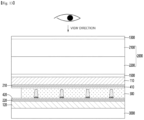
- the light emitted from the display panel 2000 or the backlight unit 3000 may move from the second substrate 120 of the light route control member to the first substrate 110.
- the light conversion part of the light route control member according to the embodiment is shown in a direction parallel or perpendicular to the outer surface of the second substrate, but the light conversion part may be formed to be inclined at a predetermined angle from the outer surface of the second substrate. Accordingly, a moire phenomenon occurring between the display panel and the light route control member may be reduced.
- the light route control member according to the embodiment may be applied to a display device that displays a display.
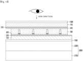
- the receiving unit when power is not applied to the light route control member as shown in FIG. 15 , the receiving unit functions as the light blocking part, so that the display device is driven in a light blocking mode, and when power is applied to the light route control member as shown in FIG. 16 , the receiving unit functions as the light transmitting part, so that the display device may be driven in an open mode.
- the light emitted from the backlight unit or the self-luminous device may move from the first substrate to the second substrate.
- the light emitted from the backlight unit or the self-luminous device may also move from the second substrate to the first substrate.
- the display device to which the light route control member according to the embodiment is applied may also be applied inside the vehicle.
- the display device including the light route control member may display a video confirming information of the vehicle and a movement route of the vehicle.
- the display device may be disposed between a driver seat and a passenger seat of the vehicle.
- the light route control member according to the embodiment may be applied to a dashboard that displays a speed, an engine, an alarm signal, and the like of the vehicle.
- the light route control member according to the embodiment may be applied to a front glass (FG) of the vehicle or right and left window glasses.
Landscapes
- Physics & Mathematics (AREA)
- Nonlinear Science (AREA)
- General Physics & Mathematics (AREA)
- Optics & Photonics (AREA)
- Engineering & Computer Science (AREA)
- Structural Engineering (AREA)
- Chemical & Material Sciences (AREA)
- Crystallography & Structural Chemistry (AREA)
- Architecture (AREA)
- Civil Engineering (AREA)
- Electrochromic Elements, Electrophoresis, Or Variable Reflection Or Absorption Elements (AREA)
Claims (11)
- Élément de commande de trajet de lumière (1000) comprenant :un premier substrat (110) ;une première électrode (210) disposée sur le premier substrat (110) ;un second substrat (120) disposé sur le second substrat (110) ;une seconde électrode (220) disposée sous le second substrat (120) ; etune partie de conversion de lumière (300) disposée entre la première électrode (210) et la seconde électrode (220),dans lequel la partie de conversion de lumière (300) inclut une partie de paroi de séparation (310) et une partie de réception (320) qui sont agencées alternativement,dans lequel l'élément de commande de trajet de lumière (1000) est agencé et positionné de manière qu'une lumière émise par une source lumineuse soit transmise dans la direction du premier substrat (110) et du second substrat (120), de manière que la lumière se déplace du premier substrat (110) vers le second substrat (120),et de manière qu'une transmission de lumière de l'élément de commande de lumière (1000) soit modifiée en fonction de l'application d'une tension à la partie de réception (320),dans lequel la partie de réception (320) inclut une dispersion (320a) et des particules de conversion de lumière (320b) dispersées dans la dispersion (320a),dans lequel une surface de contact (CS) de la partie de paroi de séparation (310) et de la partie de réception (320) présente un angle d'inclinaison Θ par rapport à un axe de référence (AX) dansune direction perpendiculaire à la surface supérieure du premier substrat (110),dans lequel l'angle d'inclinaison Θ est compris entre 1° et 10°,dans lequel la surface de contact (CS) est inclinée pour augmenter la largeur de la partie de paroi de séparation (310) tout en s'étendant dans la direction de déplacement de la lumière,dans lequel la surface de contact (CS) est inclinée pour réduire la largeur de la partie de réception (320) tout en s'étendant dans la direction de déplacement de la lumière,dans lequel la partie de paroi de séparation (310) inclut une première partie de paroi de séparation (310a)définie comme une région entre la seconde électrode (220) et la partie de réception (320) et une seconde partie de paroi de séparation (310b) définie comme une région entre la première électrode (210) et la première partie de paroi de séparation (310a) etdans lequel la résistance superficielle de la première partie de paroi de séparation (310a) est inférieure à la résistance superficielle de la seconde partie de paroi de séparation (310b).
- Élément de commande de trajet de lumière selon la revendication 1, dans lequel un indice de réfraction de la partie de paroi de séparation (310) et un indice de réfraction de la partie de réception (320) sont différents l'un de l'autre.
- Élément de commande de trajet de lumière selon la revendication 1, dans lequel la partie de paroi de séparation (310) présente un indice de réfraction compris entre 1,36 et 1,64,dans lequel la partie de réception (320) présente un indice de réfraction compris entre 1,42 et 1,45,dans lequel l'indice de réfraction de la partie de paroi de séparation (310) est supérieur à l'indice de réfraction de la partie de réception (320) dans la plage susmentionnée.
- Élément de commande de trajet de lumière selon l'une quelconque des revendications 1 à 3, dans lequel la partie de paroi de séparation (310) inclut une surface inférieure qui entre en contact avec la première électrode (210), et la partie de réception (320) inclut une surface inférieure qui entre en contact avec la première électrode (210),dans lequel la partie de paroi de séparation (310) et la partie de réception (320) sont agencées alternativement le long d'une direction,dans lequel une largeur (W2a) dans la une direction de la surface inférieure de la partie de paroi de séparation (310) et une largeur (W1a)dans la une direction de la surface inférieure de la partie de réception (320) sont différentes.
- Élément de commande de trajet de lumière selon l'une quelconque des revendications 1 à 4, dans lequel une largeur maximale de la partie de réception (320) est comprise entre 10 % et 40 % de la somme des largeurs de la partie de réception (320) et de la partie de paroi de séparation (310),
dans lequel une largeur maximale de la partie de paroi de séparation (310) est comprise entre 60 % et 90 % de la somme des largeurs de la partie de réception (320) et de la partie de paroi de séparation (310). - Élément de commande de trajet de lumière selon l'une quelconque des revendications 1 à 5, dans lequel la partie de paroi de séparation (310) inclut entre 0,01 % en poids et 10 % en poids d'un agent antistatique.
- Élément de commande de trajet de lumière selon l'une quelconque des revendications 1 à 6, dans lequel l'agent antistatique est disposé sur la surface de la partie de paroi de séparation (310).
- Élément de commande de trajet de lumière selon l'une quelconque des revendications 1 à 7, dans lequel une résistance superficielle de la partie de paroi de séparation (310) est comprise entre 105 Ω/sq et 1012 Ω/sq.
- Élément de commande de trajet de lumière selon l'une quelconque des revendications 1 à 8, dans lequel une résistance volumique de la partie de paroi de séparation (310) est comprise entre 105 Ω·cm et 1010 Ω·cm.
- Élément de commande de trajet de lumière selon l'une quelconque des revendications 1 à 9, dans lequel une résistance volumique de la seconde partie de paroi de séparation (310b) est supérieure à une résistance volumique de la première partie de paroi de séparation (310a).
- Dispositif d'affichage comprenant : un panneau d'affichage (2000) ; et
un élément de commande de trajet de lumière selon l'une quelconque des revendications 1 à 10, disposé sur le panneau d'affichage (2000).
Applications Claiming Priority (3)
| Application Number | Priority Date | Filing Date | Title |
|---|---|---|---|
| KR1020200004838A KR102783585B1 (ko) | 2020-01-14 | 2020-01-14 | 광 경로 제어 부재 및 이를 포함하는 디스플레이 장치 |
| KR1020200007802A KR102756139B1 (ko) | 2020-01-21 | 2020-01-21 | 광 경로 제어 부재 및 이를 포함하는 디스플레이 장치 |
| PCT/KR2021/000377 WO2021145638A1 (fr) | 2020-01-14 | 2021-01-12 | Élément de commande de trajet de lumière et dispositif d'affichage le comprenant |
Publications (3)
| Publication Number | Publication Date |
|---|---|
| EP4092481A1 EP4092481A1 (fr) | 2022-11-23 |
| EP4092481A4 EP4092481A4 (fr) | 2024-03-06 |
| EP4092481B1 true EP4092481B1 (fr) | 2025-04-16 |
Family
ID=76864512
Family Applications (1)
| Application Number | Title | Priority Date | Filing Date |
|---|---|---|---|
| EP21741089.3A Active EP4092481B1 (fr) | 2020-01-14 | 2021-01-12 | Élément de commande d'itinéraire lumineux et dispositif d'affichage le comprenant |
Country Status (5)
| Country | Link |
|---|---|
| US (1) | US12523912B2 (fr) |
| EP (1) | EP4092481B1 (fr) |
| JP (1) | JP7478825B2 (fr) |
| CN (1) | CN115004097B (fr) |
| WO (1) | WO2021145638A1 (fr) |
Family Cites Families (27)
| Publication number | Priority date | Publication date | Assignee | Title |
|---|---|---|---|---|
| KR100390527B1 (ko) | 2001-06-26 | 2003-07-04 | 서광석 | 기저필름 표면에 대전방지층을 형성하는 방법 및 동방법에 의한 접착테이프 |
| GB0322229D0 (en) * | 2003-09-23 | 2003-10-22 | Koninkl Philips Electronics Nv | A display |
| KR100700523B1 (ko) | 2005-02-11 | 2007-03-29 | 엘지전자 주식회사 | 충돌 대전형 전자종이 표시소자 및 그 제조 방법 |
| JP2007057724A (ja) | 2005-08-23 | 2007-03-08 | Canon Inc | 粒子移動型表示装置 |
| JP4899503B2 (ja) | 2006-02-01 | 2012-03-21 | ソニー株式会社 | 表示装置 |
| KR20090021549A (ko) | 2007-08-27 | 2009-03-04 | 영보화학 주식회사 | 엘시디 패널 보호용 대전방지 표면처리된 발포간지 |
| KR20090035228A (ko) | 2007-10-05 | 2009-04-09 | 주식회사 동진쎄미켐 | 전계 구동 표시 장치 |
| KR101413273B1 (ko) * | 2007-10-31 | 2014-06-27 | 삼성디스플레이 주식회사 | 광 검출 장치 |
| US8213082B2 (en) | 2007-12-21 | 2012-07-03 | 3M Innovative Properties Company | Light control film |
| KR101534626B1 (ko) | 2008-10-23 | 2015-07-08 | 엘지디스플레이 주식회사 | 전기영동 표시장치 및 그 격벽의 형성방법 |
| US8154790B2 (en) | 2008-10-28 | 2012-04-10 | Sipix Imaging, Inc. | Electrophoretic display structures |
| JP2011028186A (ja) | 2009-06-26 | 2011-02-10 | Fuji Xerox Co Ltd | 画像表示媒体 |
| KR20100106263A (ko) | 2010-08-27 | 2010-10-01 | 주식회사 나노브릭 | 전하를 갖는 입자를 이용한 광 투과 및 반사 조절 방법 |
| KR101241306B1 (ko) | 2010-07-29 | 2013-03-11 | 주식회사 이미지앤머터리얼스 | 윈도우 필터 시트 및 이를 이용한 윈도우 조립체 |
| KR20140085465A (ko) * | 2011-09-30 | 2014-07-07 | 쓰리엠 이노베이티브 프로퍼티즈 컴파니 | 전기적으로 전환 가능한 프라이버시 필름 및 그것을 갖는 표시 장치 |
| JP5895677B2 (ja) * | 2012-04-10 | 2016-03-30 | セイコーエプソン株式会社 | 表示シート、表示シートの製造方法、表示装置および電子機器 |
| JP6123168B2 (ja) | 2012-04-17 | 2017-05-10 | セイコーエプソン株式会社 | 表示シート、表示シートの製造方法、表示装置および電子機器 |
| JP6443691B2 (ja) | 2014-02-17 | 2018-12-26 | Tianma Japan株式会社 | 光学素子及びその製造方法,該光学素子を有する表示装置,電子機器,及び照明装置 |
| KR101756506B1 (ko) | 2014-04-29 | 2017-07-11 | (주)엘지하우시스 | 광 투과율 가변 필름 및 이를 포함한 표시 장치 |
| JP6566304B2 (ja) | 2014-09-12 | 2019-08-28 | Tianma Japan株式会社 | 光学素子及びこれを用いた表示装置,電子機器,照明装置 |
| JP2016075877A (ja) | 2014-10-09 | 2016-05-12 | 三菱鉛筆株式会社 | 電気泳動表示媒体用シート及びこれを用いた電気泳動表示媒体 |
| KR101971874B1 (ko) | 2015-02-04 | 2019-04-25 | (주)엘지하우시스 | 광투과율 가변 필름, 이를 포함한 표시 장치 및 광투과율 가변 필름의 제조 방법 |
| KR20180004879A (ko) * | 2016-07-04 | 2018-01-15 | 삼성디스플레이 주식회사 | 표시 장치 |
| KR102374549B1 (ko) | 2017-05-16 | 2022-03-14 | 엘지디스플레이 주식회사 | 광 제어장치 및 그를 포함한 투명표시장치 |
| CN109709738B (zh) | 2017-10-20 | 2019-11-22 | 京东方科技集团股份有限公司 | 防窥装置及其制造方法、显示装置 |
| JP6383081B1 (ja) * | 2017-12-21 | 2018-08-29 | デクセリアルズ株式会社 | 光硬化性樹脂組成物、及び画像表示装置の製造方法 |
| JP6753452B2 (ja) * | 2018-11-30 | 2020-09-09 | 日亜化学工業株式会社 | 発光モジュール |
-
2021
- 2021-01-12 WO PCT/KR2021/000377 patent/WO2021145638A1/fr not_active Ceased
- 2021-01-12 US US17/758,858 patent/US12523912B2/en active Active
- 2021-01-12 CN CN202180009222.8A patent/CN115004097B/zh active Active
- 2021-01-12 EP EP21741089.3A patent/EP4092481B1/fr active Active
- 2021-01-12 JP JP2022542277A patent/JP7478825B2/ja active Active
Also Published As
| Publication number | Publication date |
|---|---|
| JP2023509219A (ja) | 2023-03-07 |
| EP4092481A4 (fr) | 2024-03-06 |
| JP7478825B2 (ja) | 2024-05-07 |
| US12523912B2 (en) | 2026-01-13 |
| US20230045017A1 (en) | 2023-02-09 |
| CN115004097B (zh) | 2025-09-09 |
| CN115004097A (zh) | 2022-09-02 |
| WO2021145638A1 (fr) | 2021-07-22 |
| EP4092481A1 (fr) | 2022-11-23 |
Similar Documents
| Publication | Publication Date | Title |
|---|---|---|
| EP3848743A1 (fr) | Élément de commande de trajet optique et dispositif d'affichage le comprenant | |
| US12372845B2 (en) | Optical path control member and display device comprising same | |
| EP4006620A1 (fr) | Élément de commande de trajet optique et dispositif d'affichage le comprenant | |
| US12019319B2 (en) | Optical path control member and display device comprising same | |
| EP4092480B1 (fr) | Élément de commande de trajet optique et dispositif d'affichage le comprenant | |
| US12111533B2 (en) | Light route control member and display device having the same | |
| US20250060632A1 (en) | Optical path control member and display device including same | |
| EP4092481B1 (fr) | Élément de commande d'itinéraire lumineux et dispositif d'affichage le comprenant | |
| US12242091B2 (en) | Optical path control member and display device comprising same | |
| KR102756139B1 (ko) | 광 경로 제어 부재 및 이를 포함하는 디스플레이 장치 | |
| KR102774377B1 (ko) | 광 경로 제어 부재 및 이를 포함하는 디스플레이 장치 | |
| US12360421B2 (en) | Optical path control member and display device comprising same | |
| EP4092472B1 (fr) | Élément de commande de trajet optique et dispositif d'affichage le comprenant | |
| US20250093733A1 (en) | Light path control member and display device comprising same | |
| KR102783585B1 (ko) | 광 경로 제어 부재 및 이를 포함하는 디스플레이 장치 | |
| US20250133943A1 (en) | Light path control member and display device comprising same | |
| KR102818508B1 (ko) | 광 경로 제어 부재, 이를 포함하는 디스플레이 장치 | |
| KR102756134B1 (ko) | 광 경로 제어 부재 및 이를 포함하는 디스플레이 장치 |
Legal Events
| Date | Code | Title | Description |
|---|---|---|---|
| STAA | Information on the status of an ep patent application or granted ep patent |
Free format text: STATUS: THE INTERNATIONAL PUBLICATION HAS BEEN MADE |
|
| PUAI | Public reference made under article 153(3) epc to a published international application that has entered the european phase |
Free format text: ORIGINAL CODE: 0009012 |
|
| STAA | Information on the status of an ep patent application or granted ep patent |
Free format text: STATUS: REQUEST FOR EXAMINATION WAS MADE |
|
| 17P | Request for examination filed |
Effective date: 20220725 |
|
| AK | Designated contracting states |
Kind code of ref document: A1 Designated state(s): AL AT BE BG CH CY CZ DE DK EE ES FI FR GB GR HR HU IE IS IT LI LT LU LV MC MK MT NL NO PL PT RO RS SE SI SK SM TR |
|
| DAV | Request for validation of the european patent (deleted) | ||
| DAX | Request for extension of the european patent (deleted) | ||
| A4 | Supplementary search report drawn up and despatched |
Effective date: 20240205 |
|
| RIC1 | Information provided on ipc code assigned before grant |
Ipc: E06B 9/24 20060101ALN20240130BHEP Ipc: E06B 3/67 20060101ALN20240130BHEP Ipc: B60J 3/04 20060101ALN20240130BHEP Ipc: G02F 1/13 20060101ALN20240130BHEP Ipc: G02F 1/1681 20190101ALI20240130BHEP Ipc: G02F 1/1675 20190101ALI20240130BHEP Ipc: G02F 1/167 20190101AFI20240130BHEP |
|
| GRAP | Despatch of communication of intention to grant a patent |
Free format text: ORIGINAL CODE: EPIDOSNIGR1 |
|
| STAA | Information on the status of an ep patent application or granted ep patent |
Free format text: STATUS: GRANT OF PATENT IS INTENDED |
|
| RIC1 | Information provided on ipc code assigned before grant |
Ipc: E06B 9/24 20060101ALN20241028BHEP Ipc: E06B 3/67 20060101ALN20241028BHEP Ipc: B60J 3/04 20060101ALN20241028BHEP Ipc: G02F 1/13 20060101ALN20241028BHEP Ipc: G02F 1/1681 20190101ALI20241028BHEP Ipc: G02F 1/1675 20190101ALI20241028BHEP Ipc: G02F 1/167 20190101AFI20241028BHEP |
|
| INTG | Intention to grant announced |
Effective date: 20241112 |
|
| GRAS | Grant fee paid |
Free format text: ORIGINAL CODE: EPIDOSNIGR3 |
|
| GRAA | (expected) grant |
Free format text: ORIGINAL CODE: 0009210 |
|
| STAA | Information on the status of an ep patent application or granted ep patent |
Free format text: STATUS: THE PATENT HAS BEEN GRANTED |
|
| AK | Designated contracting states |
Kind code of ref document: B1 Designated state(s): AL AT BE BG CH CY CZ DE DK EE ES FI FR GB GR HR HU IE IS IT LI LT LU LV MC MK MT NL NO PL PT RO RS SE SI SK SM TR |
|
| REG | Reference to a national code |
Ref country code: GB Ref legal event code: FG4D |
|
| REG | Reference to a national code |
Ref country code: CH Ref legal event code: EP Ref country code: DE Ref legal event code: R096 Ref document number: 602021029250 Country of ref document: DE |
|
| REG | Reference to a national code |
Ref country code: IE Ref legal event code: FG4D |
|
| REG | Reference to a national code |
Ref country code: NL Ref legal event code: MP Effective date: 20250416 |
|
| PG25 | Lapsed in a contracting state [announced via postgrant information from national office to epo] |
Ref country code: NL Free format text: LAPSE BECAUSE OF FAILURE TO SUBMIT A TRANSLATION OF THE DESCRIPTION OR TO PAY THE FEE WITHIN THE PRESCRIBED TIME-LIMIT Effective date: 20250416 |
|
| REG | Reference to a national code |
Ref country code: AT Ref legal event code: MK05 Ref document number: 1786128 Country of ref document: AT Kind code of ref document: T Effective date: 20250416 |
|
| PG25 | Lapsed in a contracting state [announced via postgrant information from national office to epo] |
Ref country code: FI Free format text: LAPSE BECAUSE OF FAILURE TO SUBMIT A TRANSLATION OF THE DESCRIPTION OR TO PAY THE FEE WITHIN THE PRESCRIBED TIME-LIMIT Effective date: 20250416 Ref country code: PT Free format text: LAPSE BECAUSE OF FAILURE TO SUBMIT A TRANSLATION OF THE DESCRIPTION OR TO PAY THE FEE WITHIN THE PRESCRIBED TIME-LIMIT Effective date: 20250818 Ref country code: ES Free format text: LAPSE BECAUSE OF FAILURE TO SUBMIT A TRANSLATION OF THE DESCRIPTION OR TO PAY THE FEE WITHIN THE PRESCRIBED TIME-LIMIT Effective date: 20250416 |
|
| REG | Reference to a national code |
Ref country code: LT Ref legal event code: MG9D |
|
| PG25 | Lapsed in a contracting state [announced via postgrant information from national office to epo] |
Ref country code: NO Free format text: LAPSE BECAUSE OF FAILURE TO SUBMIT A TRANSLATION OF THE DESCRIPTION OR TO PAY THE FEE WITHIN THE PRESCRIBED TIME-LIMIT Effective date: 20250716 Ref country code: GR Free format text: LAPSE BECAUSE OF FAILURE TO SUBMIT A TRANSLATION OF THE DESCRIPTION OR TO PAY THE FEE WITHIN THE PRESCRIBED TIME-LIMIT Effective date: 20250717 |
|
| PG25 | Lapsed in a contracting state [announced via postgrant information from national office to epo] |
Ref country code: PL Free format text: LAPSE BECAUSE OF FAILURE TO SUBMIT A TRANSLATION OF THE DESCRIPTION OR TO PAY THE FEE WITHIN THE PRESCRIBED TIME-LIMIT Effective date: 20250416 |
|
| PG25 | Lapsed in a contracting state [announced via postgrant information from national office to epo] |
Ref country code: BG Free format text: LAPSE BECAUSE OF FAILURE TO SUBMIT A TRANSLATION OF THE DESCRIPTION OR TO PAY THE FEE WITHIN THE PRESCRIBED TIME-LIMIT Effective date: 20250416 |
|
| PG25 | Lapsed in a contracting state [announced via postgrant information from national office to epo] |
Ref country code: HR Free format text: LAPSE BECAUSE OF FAILURE TO SUBMIT A TRANSLATION OF THE DESCRIPTION OR TO PAY THE FEE WITHIN THE PRESCRIBED TIME-LIMIT Effective date: 20250416 |
|
| PG25 | Lapsed in a contracting state [announced via postgrant information from national office to epo] |
Ref country code: AT Free format text: LAPSE BECAUSE OF FAILURE TO SUBMIT A TRANSLATION OF THE DESCRIPTION OR TO PAY THE FEE WITHIN THE PRESCRIBED TIME-LIMIT Effective date: 20250416 |
|
| PG25 | Lapsed in a contracting state [announced via postgrant information from national office to epo] |
Ref country code: RS Free format text: LAPSE BECAUSE OF FAILURE TO SUBMIT A TRANSLATION OF THE DESCRIPTION OR TO PAY THE FEE WITHIN THE PRESCRIBED TIME-LIMIT Effective date: 20250716 |
|
| PG25 | Lapsed in a contracting state [announced via postgrant information from national office to epo] |
Ref country code: IS Free format text: LAPSE BECAUSE OF FAILURE TO SUBMIT A TRANSLATION OF THE DESCRIPTION OR TO PAY THE FEE WITHIN THE PRESCRIBED TIME-LIMIT Effective date: 20250816 |
|
| PG25 | Lapsed in a contracting state [announced via postgrant information from national office to epo] |
Ref country code: LV Free format text: LAPSE BECAUSE OF FAILURE TO SUBMIT A TRANSLATION OF THE DESCRIPTION OR TO PAY THE FEE WITHIN THE PRESCRIBED TIME-LIMIT Effective date: 20250416 |
|
| PG25 | Lapsed in a contracting state [announced via postgrant information from national office to epo] |
Ref country code: SM Free format text: LAPSE BECAUSE OF FAILURE TO SUBMIT A TRANSLATION OF THE DESCRIPTION OR TO PAY THE FEE WITHIN THE PRESCRIBED TIME-LIMIT Effective date: 20250416 Ref country code: DK Free format text: LAPSE BECAUSE OF FAILURE TO SUBMIT A TRANSLATION OF THE DESCRIPTION OR TO PAY THE FEE WITHIN THE PRESCRIBED TIME-LIMIT Effective date: 20250416 |
|
| REG | Reference to a national code |
Ref country code: DE Ref legal event code: R097 Ref document number: 602021029250 Country of ref document: DE |
|
| PG25 | Lapsed in a contracting state [announced via postgrant information from national office to epo] |
Ref country code: CZ Free format text: LAPSE BECAUSE OF FAILURE TO SUBMIT A TRANSLATION OF THE DESCRIPTION OR TO PAY THE FEE WITHIN THE PRESCRIBED TIME-LIMIT Effective date: 20250416 |
|
| PG25 | Lapsed in a contracting state [announced via postgrant information from national office to epo] |
Ref country code: EE Free format text: LAPSE BECAUSE OF FAILURE TO SUBMIT A TRANSLATION OF THE DESCRIPTION OR TO PAY THE FEE WITHIN THE PRESCRIBED TIME-LIMIT Effective date: 20250416 |
|
| PG25 | Lapsed in a contracting state [announced via postgrant information from national office to epo] |
Ref country code: SK Free format text: LAPSE BECAUSE OF FAILURE TO SUBMIT A TRANSLATION OF THE DESCRIPTION OR TO PAY THE FEE WITHIN THE PRESCRIBED TIME-LIMIT Effective date: 20250416 |
|
| PG25 | Lapsed in a contracting state [announced via postgrant information from national office to epo] |
Ref country code: IT Free format text: LAPSE BECAUSE OF FAILURE TO SUBMIT A TRANSLATION OF THE DESCRIPTION OR TO PAY THE FEE WITHIN THE PRESCRIBED TIME-LIMIT Effective date: 20250416 |
|
| PLBE | No opposition filed within time limit |
Free format text: ORIGINAL CODE: 0009261 |
|
| STAA | Information on the status of an ep patent application or granted ep patent |
Free format text: STATUS: NO OPPOSITION FILED WITHIN TIME LIMIT |
|
| REG | Reference to a national code |
Ref country code: CH Ref legal event code: L10 Free format text: ST27 STATUS EVENT CODE: U-0-0-L10-L00 (AS PROVIDED BY THE NATIONAL OFFICE) Effective date: 20260225 |
|
| 26N | No opposition filed |
Effective date: 20260119 |
|
| PGFP | Annual fee paid to national office [announced via postgrant information from national office to epo] |
Ref country code: DE Payment date: 20251222 Year of fee payment: 6 |