EP4092494A1 - Einstellsystem einer armbanduhr - Google Patents
Einstellsystem einer armbanduhr Download PDFInfo
- Publication number
- EP4092494A1 EP4092494A1 EP21175377.7A EP21175377A EP4092494A1 EP 4092494 A1 EP4092494 A1 EP 4092494A1 EP 21175377 A EP21175377 A EP 21175377A EP 4092494 A1 EP4092494 A1 EP 4092494A1
- Authority
- EP
- European Patent Office
- Prior art keywords
- watch
- communication module
- microcontroller
- electronic
- electronic device
- Prior art date
- Legal status (The legal status is an assumption and is not a legal conclusion. Google has not performed a legal analysis and makes no representation as to the accuracy of the status listed.)
- Pending
Links
Images

Classifications
-
- G—PHYSICS
- G04—HOROLOGY
- G04B—MECHANICALLY-DRIVEN CLOCKS OR WATCHES; MECHANICAL PARTS OF CLOCKS OR WATCHES IN GENERAL; TIME PIECES USING THE POSITION OF THE SUN, MOON OR STARS
- G04B47/00—Time-pieces combined with other articles which do not interfere with the running or the time-keeping of the time-piece
- G04B47/003—Mounting in and combined with adjustable indicating means, e.g. date indicating means adjustable by hand, marks or counters
-
- G—PHYSICS
- G04—HOROLOGY
- G04G—ELECTRONIC TIME-PIECES
- G04G17/00—Structural details; Housings
- G04G17/02—Component assemblies
- G04G17/04—Mounting of electronic components
-
- G—PHYSICS
- G04—HOROLOGY
- G04D—APPARATUS OR TOOLS SPECIALLY DESIGNED FOR MAKING OR MAINTAINING CLOCKS OR WATCHES
- G04D7/00—Measuring, counting, calibrating, testing or regulating apparatus
- G04D7/002—Electrical measuring and testing apparatus
- G04D7/003—Electrical measuring and testing apparatus for electric or electronic clocks
-
- G—PHYSICS
- G04—HOROLOGY
- G04D—APPARATUS OR TOOLS SPECIALLY DESIGNED FOR MAKING OR MAINTAINING CLOCKS OR WATCHES
- G04D7/00—Measuring, counting, calibrating, testing or regulating apparatus
- G04D7/12—Timing devices for clocks or watches for comparing the rate of the oscillating member with a standard
- G04D7/1257—Timing devices for clocks or watches for comparing the rate of the oscillating member with a standard wherein further adjustment devices are present
-
- G—PHYSICS
- G04—HOROLOGY
- G04G—ELECTRONIC TIME-PIECES
- G04G17/00—Structural details; Housings
- G04G17/02—Component assemblies
- G04G17/06—Electric connectors, e.g. conductive elastomers
-
- G—PHYSICS
- G04—HOROLOGY
- G04G—ELECTRONIC TIME-PIECES
- G04G17/00—Structural details; Housings
- G04G17/08—Housings
-
- G—PHYSICS
- G04—HOROLOGY
- G04G—ELECTRONIC TIME-PIECES
- G04G21/00—Input or output devices integrated in time-pieces
- G04G21/04—Input or output devices integrated in time-pieces using radio waves
-
- G—PHYSICS
- G04—HOROLOGY
- G04G—ELECTRONIC TIME-PIECES
- G04G5/00—Setting, i.e. correcting or changing, the time-indication
-
- G—PHYSICS
- G04—HOROLOGY
- G04G—ELECTRONIC TIME-PIECES
- G04G5/00—Setting, i.e. correcting or changing, the time-indication
- G04G5/002—Setting, i.e. correcting or changing, the time-indication brought into action by radio
-
- G—PHYSICS
- G04—HOROLOGY
- G04R—RADIO-CONTROLLED TIME-PIECES
- G04R20/00—Setting the time according to the time information carried or implied by the radio signal
- G04R20/26—Setting the time according to the time information carried or implied by the radio signal the radio signal being a near-field communication signal
-
- G—PHYSICS
- G04—HOROLOGY
- G04R—RADIO-CONTROLLED TIME-PIECES
- G04R60/00—Constructional details
- G04R60/06—Antennas attached to or integrated in clock or watch bodies
-
- H—ELECTRICITY
- H01—ELECTRIC ELEMENTS
- H01Q—ANTENNAS, i.e. RADIO AERIALS
- H01Q1/00—Details of, or arrangements associated with, antennas
- H01Q1/27—Adaptation for use in or on movable bodies
- H01Q1/273—Adaptation for carrying or wearing by persons or animals
Definitions
- the invention relates to a system for adjusting a watch, in particular an electronic watch, comprising a near-field communication module participating in the adjustment of at least one function implemented by this watch.
- the invention also relates to a method for adjusting this electronic watch.
- the object of the invention is to overcome these drawbacks by proposing a method and a system for adjusting a mechanism performing a horological function such as the perpetual calendar of an electronic watch which is simple, robust and reliable.
- the invention relates to an electronic watch provided with a case comprising at least one pair of lugs, a watch movement and a near-field communication module capable of participating in the adjustment of at least one function implemented by said watch, said communication module is connected to the movement 6 by being arranged between the horns of said at least one pair of horns 5.
- the connection establishment step comprises a sub-step of initiating a connection, in particular an automatic connection, between the watch and the electronic device as soon as this watch is located relatively to the electronic device at a distance allowing the establishment of a connection.
- Another aspect of the invention relates to a system for adjusting such an electronic watch implementing this method, the system comprising a portable electronic device provided with a near-field communication device and a microcontroller configured to control said device, the watch comprising a near-field communication module and a microcontroller configured to exchange electrical signals with this module, said watch and said apparatus being configured to be connected in near field to each other for carrying out the adjustment of the watch.
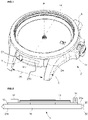
- an electronic watch 2 such as a quartz watch comprising a case 4 is shown.
- Such an electronic watch 2 is designed to be configured during an adjustment method described below and this, in particular from a portable or mobile electronic device 3 .
- This method is suitable for adjusting a mechanism performing at least one function implemented by this watch 2.
- This function can be a horological function such as the perpetual calendar of a quartz watch 2.
- This watch function can also include the date, the day, the month, the current year, the current moon phase, etc. It should be noted that, alternatively, it can be any other function likely to be performed by this watch 2.
- This system 1 therefore comprises the portable electronic device 3 as well as the said watch 2, the two being able to carry out exchanges of data 13 between them in using near-field communication technology.
- the case 4 comprises a middle part 14 which can be made of metal (eg steel, preferably stainless steel), a synthetic material (eg a composite material comprising a polymer matrix filled with fibers, typically carbon) or ceramic.
- the case 4 also comprises a back and a crystal which participate in forming, with the middle part 14, an enclosure of this case 4.
- Such an enclosure is configured to accommodate in particular the watch movement 6 comprising the microcontroller 8 and the communication module 7 in field close.
- this middle part 14 comprises two pairs of lugs 5 on which a strap is intended to be hung for wearing the watch 2 on the wrist.
- Such a bracelet is preferably made of at least one dielectric and/or electrically non-conductive material such as for example a synthetic material (for example a composite material comprising a polymer matrix loaded with fibers, typically carbon) or ceramic or even plastic such than high performance plastic.
- a synthetic material for example a composite material comprising a polymer matrix loaded with fibers, typically carbon
- ceramic or even plastic such than high performance plastic.
- the links which are directly fixed to the pairs of lugs 5 are made of at least one dielectric and/or electrically non-conductive material, the other links possibly being made of other various materials and varied.
- the pairs of lugs 5 are connected to an elastomer strap that matches the shape of the middle part 14 to completely hide an outer face 21b of a support element 15 of the communication module 7 which we describe by the after.
- the caseband 14 also comprises a through opening 23 arranged between the lugs of one of the two pairs of lugs 5.
- This opening 23 is therefore located in the between-lug 25 defined in the pair of lugs 5 located at the 6 o'clock position. watch 2, but it can also be positioned in the lug space 25 of the pair of lugs 5 located at 12 o'clock.
- This opening 23 is configured to be traversed by all or part of a body of a support element 15 of the communication module 7.
- the middle part 14 has a general symmetry of revolution around a central axis A of the case 4.
- the mechanism which implements it comprises a set of elements, including the display elements of the date, the day and month.
- the display elements are preferably analog display elements and comprise for example two hands to indicate the day and the month, and a disc to indicate the date. It is therefore understood that these display elements make it possible to indicate the date (date), the day, the month, and possibly the moon phase, automatically taking into account the different lengths of months and leap years.
- a display element such as a hand makes it possible to point to a date, day, month or moon phase indication inscribed on the dial of the watch 2, or even a display element such as a disc on which date, day, month or moon phase indications are inscribed, one of these indications facing an aperture of the dial.
- the microcontroller 8 of this watch 2 is capable of controlling the mechanism implementing the watch function, in particular the means for positioning the elements of the perpetual calendar mechanism, in particular the display elements.
- the means for positioning the elements of the perpetual calendar mechanism advantageously comprise one or more stepper motors.
- the microcontroller 8 is also connected to control means, or input interface, which can be a crown, pushers or touch pads, operable directly by the wearer of the watch 2.
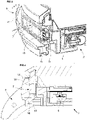
- the near-field communication module 7 is connected to the movement 6 by being arranged between the horns of said at least one pair of horns 5.
- Such a communication module 7 enables said watch 2 to be able to carry out two-way communication with the portable or mobile electronic device 3 .
- this communication module 7 is linked to the microcontroller 8 of this movement 6.
- the near-field communication module 7 is linked/connected in a removable manner to the microcontroller 8.
- Such a near-field communication module 7 implements, for example, short-range, high-frequency wireless communication technologies of the NFC type (acronym for “Near Field Communication” in English meaning “near field communication”).
- This communication module 7 operates according to technologies which are different from RFID and Bluetooth.
- This communication module 7 can for example operate in the frequency bands relating to high HF frequencies, for example at 13.56 MHz.
- the communication module 7 thus allows the realization of data exchange 13 at short distances between the watch 2 and the electronic device 3. Such distances can be between approximately 0 and 10 cm, and preferably between 0 and 5 cm.
- the communication module 7 of the watch 2 can be of the passive type with energy supplied to it by the radio frequencies emitted by the communication device 12 of the electronic device 3.
- the communication module 7 of the watch 2 can be of the active type with power supplied to it by the power unit of watch 2.
- the near-field communication module 7 comprises an electronic chip 17, at least one antenna 18 and a connector 19 making it possible to connect said module 7 to the microcontroller 8.
- Chip 17, which is connected to said at least one antenna 18, comprises hardware and software elements.
- the hardware and/or software elements of chip 17 include at least one microprocessor cooperating with memory elements.
- the communication module 7 also comprises a substrate 16 which is advantageously made in the form of a printed circuit.
- a substrate 16 also called “support” or “plate” is preferably made of high performance plastic material or laminated composites. This plastic material can be a polymer such as polyimide known as KaptonTM or even a polyester.
- the chip 17 and said at least one antenna 18 as well as the connector 19 are fixed for example by gluing on this substrate 16.
- this support element 15 comprises the substrate 16 and of course all the other components forming the communication module 7.
- This support element 15 has a shape essentially similar to that of the opening 23 included in the middle part 14 or strictly similar to that of this opening 23.
- Such an element 15 therefore comprises the internal face 21a and an external face 21b, these two faces 21a, 21b being connected by a peripheral wall 22.
- a peripheral wall 22 comprises a cavity extending over the entire the length of this wall 22 so as to participate in defining the outline of this support element 15.
- This wall 22 also comprises a sealing element 20 with the middle part 14 to prevent any ingress of liquid such as an O-ring which is arranged in said cavity.
- the support element 15 thus closes off this opening 23 of the middle part and can for this purpose also be called “shutter element”.
- This support element 15 has a thickness e which corresponds to the height or the width of this peripheral wall 22.
- This thickness e is substantially similar or strictly similar to the thickness of the portion of the middle part 14 comprising said opening 23.
- the opening 23 comprises an internal wall delimiting/defining the shape of this opening 23 and whose thickness is substantially similar or strictly similar to the thickness e of the peripheral wall 22 of the support element 15.
- This support element 15 is preferably made of at least one dielectric and/or electrically non-conductive material. It may be a synthetic material (eg in a composite material comprising a polymer matrix loaded with fibers, typically carbon) or ceramic or plastic such as high performance plastic. It will be noted that the outer face 21b of this support element 15 can be of the same color as the outer face 24 of the middle part 14 and can also have a texture substantially similar or strictly similar to this outer face 24.
- the arrangement described here of the communication module 7 between the two horns of a pair of horns 5 of the watch 2, contributes to improving the quality of the bidirectional communication signal in the near field likely to be received. or issued by this module 7.
- the communication module 7 of the watch 2 can comprise a magnetic shielding element (not shown) between the chip 17 and the said at least one antenna 18 of this module 7, and the movement 6 of the watch 2.
- This magnetic shielding element makes it possible to improve the efficiency and sensitivity of the reception/transmission of radio signals by the antenna 18 of the communication module 7 by isolating this antenna 18 from the metal components of the watch 2 included in its immediate environment.
- this magnetic shielding element makes it possible to avoid a modification of the magnetic field emitted or received by the communication module 7, which modification would be due to the presence of various metallic components of the watch 2 located in the immediate environment of the module communication module 7.
- the portable electronic device 3 also called user terminal, is a device capable of being worn and transported by a user. This is the case, for example, of a smartphone, a phablet or even a tablet. Naturally, devices requiring mains power, for example desktop computers, are excluded from this definition. Devices such as, for example, a laptop computer to which a sensor is connected by wireless or wired link, are also excluded from this definition.
- This electronic device 3 is used to transmit the adjustment parameters to the watch 2.
- This electronic device 3 comprises a box 9 in which an electronic circuit 10 is arranged.
- This electronic circuit 10 comprises a microcontroller 11 and a near-field communication device 12, both powered by a battery.
- the electronic device 3 can also include a camera and an input interface such as a touch screen or even buttons. Furthermore, the microcontroller 11 can comprise in its memory elements an optical recognition algorithm to participate in the detection of information included in particular in the dial of the watch 2 from a processing of data coming from the camera. It will be noted that the communication device 12 of this device 3 is configured to connect and exchange 13 data with the near-field communication module 7 of the watch 2.
- the invention also relates to a method making it possible to carry out the adjustment of the watch 2.
- a method is implemented by the adjustment system 1 comprising in particular the electronic device 3 and the watch 2. It makes it possible to adjust at least one function of the watch 2 such as a horological function carried out by a mechanism for implementing such a function of this watch 2 such as for example the perpetual calendar mechanism.
- This perpetual calendar mechanism allows among other things the realization of a positioning of the display elements that compose it.
- the context relates to the adjustment of this perpetual calendar mechanism, it is possible to speak of a method for adjusting a perpetual calendar mechanism of the quartz watch 2.
- This method comprises a step 30 of establishing a near field connection between the electronic device 3 and the watch 2.
- near field it should be understood here that the connection is made using NFC technology (acronym of “ Near Field Communication”, for near field communication) and insofar as the distance separating the electronic device 3 and the watch 2 is between 0 and 10 cm, preferably between 0 and 5 cm.
- this connection establishment step 30 includes a sub-step 31 of initiating, in particular automatically, a connection between the watch 2 and the electronic device 3 as soon as this watch 2 is located relative to the electronic device 3 at a distance allowing the establishment of a near field connection.
- a sub-step 31 can be initiated manually or automatically.
- this sub-step 31 When this sub-step 31 is performed manually, we then speak of a manual initiation sub-step 32a of a connection between the watch 2 and the electronic device 3 as soon as this watch 2 is located relative to the electronic device 3 at a distance allowing the establishment of a near field connection.
- the watch 2 and the electronic device 3 are arranged relative to each other at a distance allowing the establishment of a near field connection.
- the communication module 7 of the watch 2 initiates a connection process with the communication device 12 of the electronic device 3, or it is the communication device 12 of the electronic device 3 which initiates this connection process with the communication module 7 of the watch 2 and this, following an interaction, according to the case, between the user and an input interface of the watch 2, or the user and an input interface of the electronic device 3.
- this sub-step 31 When this sub-step 31 is performed automatically, the mere location of the watch 2 relative to the electronic device 3 at a distance authorizing the establishment of a near field connection, is sufficient to initiate the connection process between communication module 7 of the watch 2 and the communication device 12 of the electronic device 3.
- this sub-step 32b therefore participates in making an automatic connection, without user intervention on the watch 2 or the electronic device 3, between this watch 2 and the electronic device 3 as well as in a setting automatic watch functions of this watch 2 transparently for this user of said watch 2.
- this sub-step 32b can include an authentication phase between the module and the communication device 12 which is transparent for the user .
- an authentication phase does not require the intervention of this user.
- authentication elements are included in the memory elements of the module and of the communication device 12.
- the method comprises a verification step 33 by the microcontroller 11 of the electronic device 3 of the accuracy of a watch state datum of the watch 2
- watchmaking state data is data making it possible to represent an at least partial state of adjustment of the watch 2. It may be for example a time zone, a country code, an alarm, a geolocation, a date, a tide, a sun and/or moon phase, a UTC time, etc., set on the watch 2.
- the status datum may relate to the current date, day, month or year (or even to the current moon phase when the perpetual calendar mechanism comprises a moon phase display element, for example data relating to geolocation, hemisphere, country code, etc.), said state data representing a current setting state of the perpetual calendar mechanism, for example a position of a display element of said mechanism.
- Such a verification step 33 comprises a sub-step 34 of transmission to the communication module 7 of the watch 2 by the near-field communication device 12 and on command from the microcontroller 11 of the electronic device 3 controlling said communication device 12 an instruction for retrieving watch status data from watch 2.
- a signal relating to said instruction is then generated by microcontroller 11 to be transmitted to this communication device 12.
- the communication device 12 transmits this instruction to the communication module 7 of the watch 2.
- the verification step 33 comprises following the reception of this instruction by the watch 2, a sub-step of sending 35 to the electronic device 3 by the near-field communication module 7 on command from the microcontroller 8 of the watch 2, watchmaking status data characterizing a current setting of the watch 2 corresponding to current setting parameters of this watch 2.
- the microcontroller 8 determines the status data watchmaking characterizing a current adjustment of a mechanism relating to a watchmaking function such as the perpetual calendar.
- the status datum relates to the current date, day, month and year (and possibly to the current moon phase when the perpetual calendar mechanism includes an element of display of the moon phase, for example data relating to a geolocation, a hemisphere, a country code, etc.).
- This state datum is sufficient to represent a current state of adjustment of the perpetual calendar mechanism, in particular the position of the display elements of said mechanism.
- the microcontroller 8 then generates a signal comprising this watch status data item which is transmitted to the communication module 7.
- the communication module 7 of the watch 2 thus sends said status data item to the communications 12.
- the verification step 33 can provide a sub-step 36 for determining the watch status data from a process of reading a dial of the watch 2 performed by the electronic device 3 comprising the camera and of an optical recognition algorithm executed by the microcontroller 11 of the electronic device 3.
- a sub-step 36 then comprises a phase aimed at placing the dial of the watch 2 and the camera of the electronic device 3 facing each other.
- opposite it is meant that the dial and the camera are positioned relative to each other and at a distance such that the time display hands are in the shooting field. view of the camera.
- this sub-step 36 comprises a phase of detecting information characterizing a current setting of the watch 2 which is included in the dial of this watch 2 and this, by means of the camera and the optical recognition algorithm of the electronic device 3.
- this sub-step 36 comprises a phase of estimating the clock status datum from the information detected. This status datum can here also characterize a current adjustment of the perpetual calendar mechanism.
- the verification step 33 includes a sub-step 37 of comparing the status data with adjustment parameters, in order to verify that the adjustment of the perpetual calendar mechanism is correct.
- adjustment parameters are for example retrieved regularly or on request via an Internet network from the electronic device 3.
- adjustment parameter is meant any parameter making it possible to at least partially adjust the watch 2. It may be, for example, information on a calendar as we have seen, but also information that may relate to a time zone, a country code, an alarm, a geolocation, a date, a tide, a sun and/or moon phase, a UTC time , etc...
- the method then comprises a step 38 of sending at least one adjustment instruction to the communication module 7 in the near field of the watch 2.
- This adjustment instruction is sent by the communication device 12 in the near field and on command from the microcontroller 11 of the electronic device 3 and this, as soon as the watchmaking status datum is identified/estimated as being inaccurate.
- a control signal relating to said adjustment instruction is generated by the microcontroller 11 and then transmitted to the communication device 12 of the electronic device 3.
- This control signal is such that it corresponds to a coding adjustment parameters of the perpetual calendar mechanism, i.e. coding of a set of data relating to the current date, day, month and year (and also to the moon phase, if applicable) .
- such adjustment parameters are for example retrieved regularly or on request via an Internet network from the electronic device 3. It is noted that to carry out the coding, it is advantageous to use a dedicated application installed on the electronic device 3. If the electronic device 3 is a smartphone or a touch pad, this application is advantageously capable of generating the coding from the date, day, month, year and geolocation data given by the electronic device 3 Subsequently, this adjustment instruction is then transmitted by the communication device 12 to the communication module 7 of the watch 2.
- the method then comprises a step 39 of processing said at least one instruction received by means of the microcontroller 8 of the watch 2, in order to generate adjustment parameters for the watch 2.
- the microcontroller 8 processes the said instruction in order to obtain the current perpetual calendar.
- the method includes a step 40 of configuring the watch 2 on command from the microcontroller 8 of the watch 2, according to the adjustment parameters generated.
- This step 40 comprises a sub-step of actuating the means for positioning the elements of the perpetual calendar mechanism so as to place said elements in a position corresponding to the adjustment parameters obtained during the processing step 39.
Landscapes
- Physics & Mathematics (AREA)
- General Physics & Mathematics (AREA)
- Electric Clocks (AREA)
Priority Applications (6)
| Application Number | Priority Date | Filing Date | Title |
|---|---|---|---|
| EP21175377.7A EP4092494A1 (de) | 2021-05-21 | 2021-05-21 | Einstellsystem einer armbanduhr |
| US17/744,846 US12332608B2 (en) | 2021-05-21 | 2022-05-16 | System for setting a watch |
| JP2022080685A JP7475392B2 (ja) | 2021-05-21 | 2022-05-17 | 時計を設定するシステム |
| KR1020220060751A KR102809298B1 (ko) | 2021-05-21 | 2022-05-18 | 시계 설정 시스템 |
| CN202221212045.1U CN218938783U (zh) | 2021-05-21 | 2022-05-20 | 电子手表和用于设置电子手表的系统 |
| CN202210548390.0A CN115390422A (zh) | 2021-05-21 | 2022-05-20 | 用于设置手表的系统 |
Applications Claiming Priority (1)
| Application Number | Priority Date | Filing Date | Title |
|---|---|---|---|
| EP21175377.7A EP4092494A1 (de) | 2021-05-21 | 2021-05-21 | Einstellsystem einer armbanduhr |
Publications (1)
| Publication Number | Publication Date |
|---|---|
| EP4092494A1 true EP4092494A1 (de) | 2022-11-23 |
Family
ID=76059798
Family Applications (1)
| Application Number | Title | Priority Date | Filing Date |
|---|---|---|---|
| EP21175377.7A Pending EP4092494A1 (de) | 2021-05-21 | 2021-05-21 | Einstellsystem einer armbanduhr |
Country Status (5)
| Country | Link |
|---|---|
| US (1) | US12332608B2 (de) |
| EP (1) | EP4092494A1 (de) |
| JP (1) | JP7475392B2 (de) |
| KR (1) | KR102809298B1 (de) |
| CN (2) | CN115390422A (de) |
Cited By (1)
| Publication number | Priority date | Publication date | Assignee | Title |
|---|---|---|---|---|
| EP4745679A1 (de) | 2024-11-14 | 2026-05-20 | The Swatch Group Research and Development Ltd | Magnetischer mechanismus zur steuerung und/oder zum antrieb durch ein armbanduhrgehäuse |
Families Citing this family (2)
| Publication number | Priority date | Publication date | Assignee | Title |
|---|---|---|---|---|
| EP4092494A1 (de) | 2021-05-21 | 2022-11-23 | ETA SA Manufacture Horlogère Suisse | Einstellsystem einer armbanduhr |
| JP7826167B2 (ja) * | 2022-11-09 | 2026-03-09 | 株式会社三共 | 遊技機 |
Citations (6)
| Publication number | Priority date | Publication date | Assignee | Title |
|---|---|---|---|---|
| CH711303A1 (fr) * | 2015-07-09 | 2017-01-13 | Soprod Sa | Dispositif de correction pour un mouvement horloger mécanique. |
| US20170179580A1 (en) * | 2015-12-22 | 2017-06-22 | Lg Electronics Inc. | Electronic device |
| EP3211491A1 (de) * | 2016-02-26 | 2017-08-30 | ETA SA Manufacture Horlogère Suisse | Automatische einstellmethode der stundenanzeige einer armbanduhr |
| CH712578B1 (fr) * | 2016-12-09 | 2017-12-15 | Swatch Group Res & Dev Ltd | Procédé de réglage de la marche d'une montre mécanique. |
| WO2019007116A1 (zh) * | 2017-07-06 | 2019-01-10 | 广东乐源数字技术有限公司 | 一种带独立蓝牙发射装置的智能手表 |
| US20200379411A1 (en) * | 2017-03-29 | 2020-12-03 | Citizen Watch Co., Ltd. | Analog electric watch system and analog electronic watch |
Family Cites Families (17)
| Publication number | Priority date | Publication date | Assignee | Title |
|---|---|---|---|---|
| JP5055924B2 (ja) * | 2006-09-29 | 2012-10-24 | カシオ計算機株式会社 | アンテナ装置及び電子機器 |
| FR2963141B1 (fr) * | 2010-07-20 | 2012-08-31 | Oberthur Technologies | Etiquette electronique sans contact |
| JP5935422B2 (ja) * | 2012-03-19 | 2016-06-15 | カシオ計算機株式会社 | 感度調整装置及び電波通信機器 |
| CN203365964U (zh) | 2013-04-12 | 2013-12-25 | 上海与德通讯技术有限公司 | 电子腕表 |
| US9356661B2 (en) * | 2014-04-23 | 2016-05-31 | Apple Inc. | Electronic device with near-field antenna operating through display |
| CN103995461B (zh) | 2014-05-14 | 2016-03-30 | 王辉 | 蓝牙无线电波校零、授时系统及方法 |
| KR101458748B1 (ko) | 2014-07-17 | 2014-11-12 | 박동원 | 일반 휴대폰과 동일한 전화번호를 사용하는 손목시계형 휴대폰을 절전하며 사용하는 방법 |
| CN104199273A (zh) | 2014-09-17 | 2014-12-10 | 宝捷时计电子(深圳)有限公司 | 无按键和无把的手表 |
| CN104679334B (zh) | 2015-03-02 | 2018-04-20 | 南京物联传感技术有限公司 | 一种数据交互显示系统及方法 |
| CN104777744A (zh) | 2015-03-30 | 2015-07-15 | 陈德林 | 一种通过蓝牙技术实现表针对时的方法 |
| EP3112958B1 (de) * | 2015-07-01 | 2022-03-16 | Bulgari Horlogerie S.A. | Uhr umfassend eine vorrichtung zur nahfeldkommunikation |
| TWM516175U (zh) * | 2015-07-23 | 2016-01-21 | 廣達電腦股份有限公司 | 智慧型手錶 |
| CH712176B1 (fr) | 2016-02-26 | 2021-03-15 | Eta Sa Mft Horlogere Suisse | Méthode de réglage automatique de l'heure d'une montre. |
| JP6759908B2 (ja) | 2016-09-14 | 2020-09-23 | カシオ計算機株式会社 | 電子時計、電子時計の時刻変更方法、および、プログラム |
| CN107329397B (zh) | 2017-07-26 | 2023-06-20 | 歌尔科技有限公司 | 一种轻智能手表校准方法、装置和轻智能手表 |
| JP7073833B2 (ja) * | 2018-03-23 | 2022-05-24 | セイコーエプソン株式会社 | 電子時計 |
| EP4092494A1 (de) | 2021-05-21 | 2022-11-23 | ETA SA Manufacture Horlogère Suisse | Einstellsystem einer armbanduhr |
-
2021
- 2021-05-21 EP EP21175377.7A patent/EP4092494A1/de active Pending
-
2022
- 2022-05-16 US US17/744,846 patent/US12332608B2/en active Active
- 2022-05-17 JP JP2022080685A patent/JP7475392B2/ja active Active
- 2022-05-18 KR KR1020220060751A patent/KR102809298B1/ko active Active
- 2022-05-20 CN CN202210548390.0A patent/CN115390422A/zh active Pending
- 2022-05-20 CN CN202221212045.1U patent/CN218938783U/zh active Active
Patent Citations (6)
| Publication number | Priority date | Publication date | Assignee | Title |
|---|---|---|---|---|
| CH711303A1 (fr) * | 2015-07-09 | 2017-01-13 | Soprod Sa | Dispositif de correction pour un mouvement horloger mécanique. |
| US20170179580A1 (en) * | 2015-12-22 | 2017-06-22 | Lg Electronics Inc. | Electronic device |
| EP3211491A1 (de) * | 2016-02-26 | 2017-08-30 | ETA SA Manufacture Horlogère Suisse | Automatische einstellmethode der stundenanzeige einer armbanduhr |
| CH712578B1 (fr) * | 2016-12-09 | 2017-12-15 | Swatch Group Res & Dev Ltd | Procédé de réglage de la marche d'une montre mécanique. |
| US20200379411A1 (en) * | 2017-03-29 | 2020-12-03 | Citizen Watch Co., Ltd. | Analog electric watch system and analog electronic watch |
| WO2019007116A1 (zh) * | 2017-07-06 | 2019-01-10 | 广东乐源数字技术有限公司 | 一种带独立蓝牙发射装置的智能手表 |
Cited By (1)
| Publication number | Priority date | Publication date | Assignee | Title |
|---|---|---|---|---|
| EP4745679A1 (de) | 2024-11-14 | 2026-05-20 | The Swatch Group Research and Development Ltd | Magnetischer mechanismus zur steuerung und/oder zum antrieb durch ein armbanduhrgehäuse |
Also Published As
| Publication number | Publication date |
|---|---|
| KR102809298B1 (ko) | 2025-05-16 |
| JP7475392B2 (ja) | 2024-04-26 |
| US20220373978A1 (en) | 2022-11-24 |
| US12332608B2 (en) | 2025-06-17 |
| CN218938783U (zh) | 2023-04-28 |
| CN115390422A (zh) | 2022-11-25 |
| KR20220157900A (ko) | 2022-11-29 |
| JP2022179402A (ja) | 2022-12-02 |
Similar Documents
| Publication | Publication Date | Title |
|---|---|---|
| EP3579061B1 (de) | Schrein für eine elektromechanische uhr und baugruppe mit diesem | |
| EP3420416B1 (de) | Automatische einstellmethode der stundenanzeige einer armbanduhr | |
| EP2689293A1 (de) | Multifunktionsgehäuse | |
| EP3339984B1 (de) | Intelligente vorrichtung zum aufziehen von armbanduhren | |
| US12332608B2 (en) | System for setting a watch | |
| EP3379347B1 (de) | Verfahren zur regulierung der gangfrequenz einer elektronischen uhr | |
| EP3839665B1 (de) | Einstellverfahren einer elektronischen uhr | |
| EP4174586A1 (de) | Uhreneinheit, die eine armbanduhr und ein uhrzeitkorrektursystem umfasst | |
| CH718656A2 (fr) | Système de réglage d'une montre. | |
| WO2017006162A2 (fr) | Montre hybride reversible | |
| CH712176B1 (fr) | Méthode de réglage automatique de l'heure d'une montre. | |
| CH716962A2 (fr) | Procédé de réglage d'une montre électronique. | |
| CH711300A1 (fr) | Montre hybride réversible. | |
| CH711303A1 (fr) | Dispositif de correction pour un mouvement horloger mécanique. | |
| EP4092493A1 (de) | Armbanduhr mit einem nahfeld-kommunikationsgerät | |
| EP3647885B1 (de) | Steuerungsverfahren des stromverbrauchs einer armbanduhr | |
| EP3379346B1 (de) | Einstellverfahren einer quartzuhr | |
| CH714264B1 (fr) | Écrin pour montre électromécanique et ensemble le comprenant. | |
| CH713592B1 (fr) | Procédé de réglage d'une montre à quartz. | |
| CH719100A2 (fr) | Ensemble horloger comprenant une montre et un système de correction de l'heure. | |
| EP4095623A1 (de) | Vorrichtung zum aufziehen oder einstellen und kontrollieren einer armbanduhr | |
| WO2008155274A1 (fr) | Ensemble comprenant une montre et son ecrin | |
| CH713643A2 (fr) | Procédé de réglage de la fréquence de marche d'une montre électronique. |
Legal Events
| Date | Code | Title | Description |
|---|---|---|---|
| PUAI | Public reference made under article 153(3) epc to a published international application that has entered the european phase |
Free format text: ORIGINAL CODE: 0009012 |
|
| STAA | Information on the status of an ep patent application or granted ep patent |
Free format text: STATUS: THE APPLICATION HAS BEEN PUBLISHED |
|
| AK | Designated contracting states |
Kind code of ref document: A1 Designated state(s): AL AT BE BG CH CY CZ DE DK EE ES FI FR GB GR HR HU IE IS IT LI LT LU LV MC MK MT NL NO PL PT RO RS SE SI SK SM TR |
|
| STAA | Information on the status of an ep patent application or granted ep patent |
Free format text: STATUS: REQUEST FOR EXAMINATION WAS MADE |
|
| 17P | Request for examination filed |
Effective date: 20230523 |
|
| RBV | Designated contracting states (corrected) |
Designated state(s): AL AT BE BG CH CY CZ DE DK EE ES FI FR GB GR HR HU IE IS IT LI LT LU LV MC MK MT NL NO PL PT RO RS SE SI SK SM TR |
|
| P01 | Opt-out of the competence of the unified patent court (upc) registered |
Effective date: 20230701 |
|
| STAA | Information on the status of an ep patent application or granted ep patent |
Free format text: STATUS: EXAMINATION IS IN PROGRESS |
|
| 17Q | First examination report despatched |
Effective date: 20240715 |
|
| GRAP | Despatch of communication of intention to grant a patent |
Free format text: ORIGINAL CODE: EPIDOSNIGR1 |
|
| STAA | Information on the status of an ep patent application or granted ep patent |
Free format text: STATUS: GRANT OF PATENT IS INTENDED |
|
| INTG | Intention to grant announced |
Effective date: 20260714 |