EP4092794A1 - Bloc-batterie de véhicule et procédé d'assemblage associé - Google Patents
Bloc-batterie de véhicule et procédé d'assemblage associé Download PDFInfo
- Publication number
- EP4092794A1 EP4092794A1 EP22172722.5A EP22172722A EP4092794A1 EP 4092794 A1 EP4092794 A1 EP 4092794A1 EP 22172722 A EP22172722 A EP 22172722A EP 4092794 A1 EP4092794 A1 EP 4092794A1
- Authority
- EP
- European Patent Office
- Prior art keywords
- battery pack
- module
- cells
- compression
- bulkheads
- Prior art date
- Legal status (The legal status is an assumption and is not a legal conclusion. Google has not performed a legal analysis and makes no representation as to the accuracy of the status listed.)
- Pending
Links
- 238000000034 method Methods 0.000 title claims description 13
- 238000003780 insertion Methods 0.000 claims abstract description 58
- 230000037431 insertion Effects 0.000 claims abstract description 58
- 230000006835 compression Effects 0.000 claims abstract description 39
- 238000007906 compression Methods 0.000 claims abstract description 39
- 229910052799 carbon Inorganic materials 0.000 claims abstract description 23
- 238000001816 cooling Methods 0.000 claims description 15
- 238000007789 sealing Methods 0.000 claims description 6
- 239000012530 fluid Substances 0.000 claims description 5
- 239000004033 plastic Substances 0.000 claims description 3
- 229920003023 plastic Polymers 0.000 claims description 3
- -1 polytetrafluoroethylene Polymers 0.000 claims description 3
- 229920001343 polytetrafluoroethylene Polymers 0.000 claims description 2
- 239000004810 polytetrafluoroethylene Substances 0.000 claims description 2
- 230000003068 static effect Effects 0.000 claims description 2
- 238000012546 transfer Methods 0.000 claims description 2
- CIWBSHSKHKDKBQ-JLAZNSOCSA-N Ascorbic acid Chemical compound OC[C@H](O)[C@H]1OC(=O)C(O)=C1O CIWBSHSKHKDKBQ-JLAZNSOCSA-N 0.000 description 11
- 239000000758 substrate Substances 0.000 description 11
- 238000003860 storage Methods 0.000 description 10
- 230000004224 protection Effects 0.000 description 6
- 239000010410 layer Substances 0.000 description 4
- 238000000926 separation method Methods 0.000 description 4
- 239000006260 foam Substances 0.000 description 3
- 229910052744 lithium Inorganic materials 0.000 description 3
- 230000002093 peripheral effect Effects 0.000 description 3
- WHXSMMKQMYFTQS-UHFFFAOYSA-N Lithium Chemical compound [Li] WHXSMMKQMYFTQS-UHFFFAOYSA-N 0.000 description 2
- 239000011149 active material Substances 0.000 description 2
- 239000004020 conductor Substances 0.000 description 2
- 238000007599 discharging Methods 0.000 description 2
- 239000011810 insulating material Substances 0.000 description 2
- 238000012423 maintenance Methods 0.000 description 2
- 238000004519 manufacturing process Methods 0.000 description 2
- 239000000463 material Substances 0.000 description 2
- 238000013022 venting Methods 0.000 description 2
- OKTJSMMVPCPJKN-UHFFFAOYSA-N Carbon Chemical compound [C] OKTJSMMVPCPJKN-UHFFFAOYSA-N 0.000 description 1
- HBBGRARXTFLTSG-UHFFFAOYSA-N Lithium ion Chemical compound [Li+] HBBGRARXTFLTSG-UHFFFAOYSA-N 0.000 description 1
- 239000004411 aluminium Substances 0.000 description 1
- 229910052782 aluminium Inorganic materials 0.000 description 1
- XAGFODPZIPBFFR-UHFFFAOYSA-N aluminium Chemical compound [Al] XAGFODPZIPBFFR-UHFFFAOYSA-N 0.000 description 1
- 230000005540 biological transmission Effects 0.000 description 1
- 230000015572 biosynthetic process Effects 0.000 description 1
- 238000002144 chemical decomposition reaction Methods 0.000 description 1
- 238000006243 chemical reaction Methods 0.000 description 1
- 230000000295 complement effect Effects 0.000 description 1
- 239000002131 composite material Substances 0.000 description 1
- 230000008878 coupling Effects 0.000 description 1
- 238000010168 coupling process Methods 0.000 description 1
- 238000005859 coupling reaction Methods 0.000 description 1
- 238000005520 cutting process Methods 0.000 description 1
- 238000009826 distribution Methods 0.000 description 1
- 239000003792 electrolyte Substances 0.000 description 1
- 239000000835 fiber Substances 0.000 description 1
- 239000003517 fume Substances 0.000 description 1
- 239000007789 gas Substances 0.000 description 1
- 230000017525 heat dissipation Effects 0.000 description 1
- 238000009434 installation Methods 0.000 description 1
- 238000009413 insulation Methods 0.000 description 1
- 239000012212 insulator Substances 0.000 description 1
- 239000007788 liquid Substances 0.000 description 1
- 239000011244 liquid electrolyte Substances 0.000 description 1
- 229910001416 lithium ion Inorganic materials 0.000 description 1
- 238000005259 measurement Methods 0.000 description 1
- 229910052751 metal Inorganic materials 0.000 description 1
- 239000002184 metal Substances 0.000 description 1
- 238000013021 overheating Methods 0.000 description 1
- 230000003647 oxidation Effects 0.000 description 1
- 238000007254 oxidation reaction Methods 0.000 description 1
- 229920003223 poly(pyromellitimide-1,4-diphenyl ether) Polymers 0.000 description 1
- 229920001721 polyimide Polymers 0.000 description 1
- 229920000642 polymer Polymers 0.000 description 1
- 238000004321 preservation Methods 0.000 description 1
- 230000001681 protective effect Effects 0.000 description 1
- 239000011241 protective layer Substances 0.000 description 1
- 235000019992 sake Nutrition 0.000 description 1
- 239000000523 sample Substances 0.000 description 1
- 239000000126 substance Substances 0.000 description 1
Images


Classifications
-
- H—ELECTRICITY
- H01—ELECTRIC ELEMENTS
- H01M—PROCESSES OR MEANS, e.g. BATTERIES, FOR THE DIRECT CONVERSION OF CHEMICAL ENERGY INTO ELECTRICAL ENERGY
- H01M10/00—Secondary cells; Manufacture thereof
- H01M10/04—Construction or manufacture in general
- H01M10/0481—Compression means other than compression means for stacks of electrodes and separators
-
- H—ELECTRICITY
- H01—ELECTRIC ELEMENTS
- H01M—PROCESSES OR MEANS, e.g. BATTERIES, FOR THE DIRECT CONVERSION OF CHEMICAL ENERGY INTO ELECTRICAL ENERGY
- H01M50/00—Constructional details or processes of manufacture of the non-active parts of electrochemical cells other than fuel cells, e.g. hybrid cells
- H01M50/20—Mountings; Secondary casings or frames; Racks, modules or packs; Suspension devices; Shock absorbers; Transport or carrying devices; Holders
- H01M50/289—Mountings; Secondary casings or frames; Racks, modules or packs; Suspension devices; Shock absorbers; Transport or carrying devices; Holders characterised by spacing elements or positioning means within frames, racks or packs
-
- B—PERFORMING OPERATIONS; TRANSPORTING
- B60—VEHICLES IN GENERAL
- B60K—ARRANGEMENT OR MOUNTING OF PROPULSION UNITS OR OF TRANSMISSIONS IN VEHICLES; ARRANGEMENT OR MOUNTING OF PLURAL DIVERSE PRIME-MOVERS IN VEHICLES; AUXILIARY DRIVES FOR VEHICLES; INSTRUMENTATION OR DASHBOARDS FOR VEHICLES; ARRANGEMENTS IN CONNECTION WITH COOLING, AIR INTAKE, GAS EXHAUST OR FUEL SUPPLY OF PROPULSION UNITS IN VEHICLES
- B60K1/00—Arrangement or mounting of electrical propulsion units
- B60K1/04—Arrangement or mounting of electrical propulsion units of the electric storage means for propulsion
-
- B—PERFORMING OPERATIONS; TRANSPORTING
- B60—VEHICLES IN GENERAL
- B60L—PROPULSION OF ELECTRICALLY-PROPELLED VEHICLES; SUPPLYING ELECTRIC POWER FOR AUXILIARY EQUIPMENT OF ELECTRICALLY-PROPELLED VEHICLES; ELECTRODYNAMIC BRAKE SYSTEMS FOR VEHICLES IN GENERAL; MAGNETIC SUSPENSION OR LEVITATION FOR VEHICLES; MONITORING OPERATING VARIABLES OF ELECTRICALLY-PROPELLED VEHICLES; ELECTRIC SAFETY DEVICES FOR ELECTRICALLY-PROPELLED VEHICLES
- B60L50/00—Electric propulsion with power supplied within the vehicle
- B60L50/50—Electric propulsion with power supplied within the vehicle using propulsion power supplied by batteries or fuel cells
- B60L50/60—Electric propulsion with power supplied within the vehicle using propulsion power supplied by batteries or fuel cells using power supplied by batteries
- B60L50/64—Constructional details of batteries specially adapted for electric vehicles
-
- H—ELECTRICITY
- H01—ELECTRIC ELEMENTS
- H01M—PROCESSES OR MEANS, e.g. BATTERIES, FOR THE DIRECT CONVERSION OF CHEMICAL ENERGY INTO ELECTRICAL ENERGY
- H01M10/00—Secondary cells; Manufacture thereof
- H01M10/60—Heating or cooling; Temperature control
- H01M10/61—Types of temperature control
- H01M10/613—Cooling or keeping cold
-
- H—ELECTRICITY
- H01—ELECTRIC ELEMENTS
- H01M—PROCESSES OR MEANS, e.g. BATTERIES, FOR THE DIRECT CONVERSION OF CHEMICAL ENERGY INTO ELECTRICAL ENERGY
- H01M10/00—Secondary cells; Manufacture thereof
- H01M10/60—Heating or cooling; Temperature control
- H01M10/62—Heating or cooling; Temperature control specially adapted for specific applications
- H01M10/625—Vehicles
-
- H—ELECTRICITY
- H01—ELECTRIC ELEMENTS
- H01M—PROCESSES OR MEANS, e.g. BATTERIES, FOR THE DIRECT CONVERSION OF CHEMICAL ENERGY INTO ELECTRICAL ENERGY
- H01M10/00—Secondary cells; Manufacture thereof
- H01M10/60—Heating or cooling; Temperature control
- H01M10/64—Heating or cooling; Temperature control characterised by the shape of the cells
- H01M10/647—Prismatic or flat cells, e.g. pouch cells
-
- H—ELECTRICITY
- H01—ELECTRIC ELEMENTS
- H01M—PROCESSES OR MEANS, e.g. BATTERIES, FOR THE DIRECT CONVERSION OF CHEMICAL ENERGY INTO ELECTRICAL ENERGY
- H01M10/00—Secondary cells; Manufacture thereof
- H01M10/60—Heating or cooling; Temperature control
- H01M10/65—Means for temperature control structurally associated with the cells
- H01M10/653—Means for temperature control structurally associated with the cells characterised by electrically insulating or thermally conductive materials
-
- H—ELECTRICITY
- H01—ELECTRIC ELEMENTS
- H01M—PROCESSES OR MEANS, e.g. BATTERIES, FOR THE DIRECT CONVERSION OF CHEMICAL ENERGY INTO ELECTRICAL ENERGY
- H01M10/00—Secondary cells; Manufacture thereof
- H01M10/60—Heating or cooling; Temperature control
- H01M10/65—Means for temperature control structurally associated with the cells
- H01M10/655—Solid structures for heat exchange or heat conduction
- H01M10/6551—Surfaces specially adapted for heat dissipation or radiation, e.g. fins or coatings
-
- H—ELECTRICITY
- H01—ELECTRIC ELEMENTS
- H01M—PROCESSES OR MEANS, e.g. BATTERIES, FOR THE DIRECT CONVERSION OF CHEMICAL ENERGY INTO ELECTRICAL ENERGY
- H01M10/00—Secondary cells; Manufacture thereof
- H01M10/60—Heating or cooling; Temperature control
- H01M10/65—Means for temperature control structurally associated with the cells
- H01M10/655—Solid structures for heat exchange or heat conduction
- H01M10/6554—Rods or plates
- H01M10/6555—Rods or plates arranged between the cells
-
- H—ELECTRICITY
- H01—ELECTRIC ELEMENTS
- H01M—PROCESSES OR MEANS, e.g. BATTERIES, FOR THE DIRECT CONVERSION OF CHEMICAL ENERGY INTO ELECTRICAL ENERGY
- H01M50/00—Constructional details or processes of manufacture of the non-active parts of electrochemical cells other than fuel cells, e.g. hybrid cells
- H01M50/20—Mountings; Secondary casings or frames; Racks, modules or packs; Suspension devices; Shock absorbers; Transport or carrying devices; Holders
- H01M50/204—Racks, modules or packs for multiple batteries or multiple cells
- H01M50/207—Racks, modules or packs for multiple batteries or multiple cells characterised by their shape
- H01M50/209—Racks, modules or packs for multiple batteries or multiple cells characterised by their shape adapted for prismatic or rectangular cells
-
- H—ELECTRICITY
- H01—ELECTRIC ELEMENTS
- H01M—PROCESSES OR MEANS, e.g. BATTERIES, FOR THE DIRECT CONVERSION OF CHEMICAL ENERGY INTO ELECTRICAL ENERGY
- H01M50/00—Constructional details or processes of manufacture of the non-active parts of electrochemical cells other than fuel cells, e.g. hybrid cells
- H01M50/20—Mountings; Secondary casings or frames; Racks, modules or packs; Suspension devices; Shock absorbers; Transport or carrying devices; Holders
- H01M50/204—Racks, modules or packs for multiple batteries or multiple cells
- H01M50/207—Racks, modules or packs for multiple batteries or multiple cells characterised by their shape
- H01M50/211—Racks, modules or packs for multiple batteries or multiple cells characterised by their shape adapted for pouch cells
-
- H—ELECTRICITY
- H01—ELECTRIC ELEMENTS
- H01M—PROCESSES OR MEANS, e.g. BATTERIES, FOR THE DIRECT CONVERSION OF CHEMICAL ENERGY INTO ELECTRICAL ENERGY
- H01M50/00—Constructional details or processes of manufacture of the non-active parts of electrochemical cells other than fuel cells, e.g. hybrid cells
- H01M50/20—Mountings; Secondary casings or frames; Racks, modules or packs; Suspension devices; Shock absorbers; Transport or carrying devices; Holders
- H01M50/244—Secondary casings; Racks; Suspension devices; Carrying devices; Holders characterised by their mounting method
-
- H—ELECTRICITY
- H01—ELECTRIC ELEMENTS
- H01M—PROCESSES OR MEANS, e.g. BATTERIES, FOR THE DIRECT CONVERSION OF CHEMICAL ENERGY INTO ELECTRICAL ENERGY
- H01M50/00—Constructional details or processes of manufacture of the non-active parts of electrochemical cells other than fuel cells, e.g. hybrid cells
- H01M50/20—Mountings; Secondary casings or frames; Racks, modules or packs; Suspension devices; Shock absorbers; Transport or carrying devices; Holders
- H01M50/249—Mountings; Secondary casings or frames; Racks, modules or packs; Suspension devices; Shock absorbers; Transport or carrying devices; Holders specially adapted for aircraft or vehicles, e.g. cars or trains
-
- H—ELECTRICITY
- H01—ELECTRIC ELEMENTS
- H01M—PROCESSES OR MEANS, e.g. BATTERIES, FOR THE DIRECT CONVERSION OF CHEMICAL ENERGY INTO ELECTRICAL ENERGY
- H01M50/00—Constructional details or processes of manufacture of the non-active parts of electrochemical cells other than fuel cells, e.g. hybrid cells
- H01M50/20—Mountings; Secondary casings or frames; Racks, modules or packs; Suspension devices; Shock absorbers; Transport or carrying devices; Holders
- H01M50/289—Mountings; Secondary casings or frames; Racks, modules or packs; Suspension devices; Shock absorbers; Transport or carrying devices; Holders characterised by spacing elements or positioning means within frames, racks or packs
- H01M50/291—Mountings; Secondary casings or frames; Racks, modules or packs; Suspension devices; Shock absorbers; Transport or carrying devices; Holders characterised by spacing elements or positioning means within frames, racks or packs characterised by their shape
-
- B—PERFORMING OPERATIONS; TRANSPORTING
- B60—VEHICLES IN GENERAL
- B60K—ARRANGEMENT OR MOUNTING OF PROPULSION UNITS OR OF TRANSMISSIONS IN VEHICLES; ARRANGEMENT OR MOUNTING OF PLURAL DIVERSE PRIME-MOVERS IN VEHICLES; AUXILIARY DRIVES FOR VEHICLES; INSTRUMENTATION OR DASHBOARDS FOR VEHICLES; ARRANGEMENTS IN CONNECTION WITH COOLING, AIR INTAKE, GAS EXHAUST OR FUEL SUPPLY OF PROPULSION UNITS IN VEHICLES
- B60K11/00—Arrangement in connection with cooling of propulsion units
- B60K11/06—Arrangement in connection with cooling of propulsion units with air cooling
-
- B—PERFORMING OPERATIONS; TRANSPORTING
- B60—VEHICLES IN GENERAL
- B60K—ARRANGEMENT OR MOUNTING OF PROPULSION UNITS OR OF TRANSMISSIONS IN VEHICLES; ARRANGEMENT OR MOUNTING OF PLURAL DIVERSE PRIME-MOVERS IN VEHICLES; AUXILIARY DRIVES FOR VEHICLES; INSTRUMENTATION OR DASHBOARDS FOR VEHICLES; ARRANGEMENTS IN CONNECTION WITH COOLING, AIR INTAKE, GAS EXHAUST OR FUEL SUPPLY OF PROPULSION UNITS IN VEHICLES
- B60K1/00—Arrangement or mounting of electrical propulsion units
- B60K2001/003—Arrangement or mounting of electrical propulsion units with means for cooling the electrical propulsion units
- B60K2001/005—Arrangement or mounting of electrical propulsion units with means for cooling the electrical propulsion units the electric storage means
-
- B—PERFORMING OPERATIONS; TRANSPORTING
- B60—VEHICLES IN GENERAL
- B60K—ARRANGEMENT OR MOUNTING OF PROPULSION UNITS OR OF TRANSMISSIONS IN VEHICLES; ARRANGEMENT OR MOUNTING OF PLURAL DIVERSE PRIME-MOVERS IN VEHICLES; AUXILIARY DRIVES FOR VEHICLES; INSTRUMENTATION OR DASHBOARDS FOR VEHICLES; ARRANGEMENTS IN CONNECTION WITH COOLING, AIR INTAKE, GAS EXHAUST OR FUEL SUPPLY OF PROPULSION UNITS IN VEHICLES
- B60K1/00—Arrangement or mounting of electrical propulsion units
- B60K1/04—Arrangement or mounting of electrical propulsion units of the electric storage means for propulsion
- B60K2001/0405—Arrangement or mounting of electrical propulsion units of the electric storage means for propulsion characterised by their position
- B60K2001/0416—Arrangement in the rear part of the vehicle
-
- B—PERFORMING OPERATIONS; TRANSPORTING
- B60—VEHICLES IN GENERAL
- B60K—ARRANGEMENT OR MOUNTING OF PROPULSION UNITS OR OF TRANSMISSIONS IN VEHICLES; ARRANGEMENT OR MOUNTING OF PLURAL DIVERSE PRIME-MOVERS IN VEHICLES; AUXILIARY DRIVES FOR VEHICLES; INSTRUMENTATION OR DASHBOARDS FOR VEHICLES; ARRANGEMENTS IN CONNECTION WITH COOLING, AIR INTAKE, GAS EXHAUST OR FUEL SUPPLY OF PROPULSION UNITS IN VEHICLES
- B60K1/00—Arrangement or mounting of electrical propulsion units
- B60K1/04—Arrangement or mounting of electrical propulsion units of the electric storage means for propulsion
- B60K2001/0405—Arrangement or mounting of electrical propulsion units of the electric storage means for propulsion characterised by their position
- B60K2001/0438—Arrangement under the floor
-
- H—ELECTRICITY
- H01—ELECTRIC ELEMENTS
- H01M—PROCESSES OR MEANS, e.g. BATTERIES, FOR THE DIRECT CONVERSION OF CHEMICAL ENERGY INTO ELECTRICAL ENERGY
- H01M2220/00—Batteries for particular applications
- H01M2220/20—Batteries in motive systems, e.g. vehicle, ship, plane
-
- H—ELECTRICITY
- H01—ELECTRIC ELEMENTS
- H01M—PROCESSES OR MEANS, e.g. BATTERIES, FOR THE DIRECT CONVERSION OF CHEMICAL ENERGY INTO ELECTRICAL ENERGY
- H01M50/00—Constructional details or processes of manufacture of the non-active parts of electrochemical cells other than fuel cells, e.g. hybrid cells
- H01M50/50—Current conducting connections for cells or batteries
- H01M50/502—Interconnectors for connecting terminals of adjacent batteries; Interconnectors for connecting cells outside a battery casing
-
- Y—GENERAL TAGGING OF NEW TECHNOLOGICAL DEVELOPMENTS; GENERAL TAGGING OF CROSS-SECTIONAL TECHNOLOGIES SPANNING OVER SEVERAL SECTIONS OF THE IPC; TECHNICAL SUBJECTS COVERED BY FORMER USPC CROSS-REFERENCE ART COLLECTIONS [XRACs] AND DIGESTS
- Y02—TECHNOLOGIES OR APPLICATIONS FOR MITIGATION OR ADAPTATION AGAINST CLIMATE CHANGE
- Y02E—REDUCTION OF GREENHOUSE GAS [GHG] EMISSIONS, RELATED TO ENERGY GENERATION, TRANSMISSION OR DISTRIBUTION
- Y02E60/00—Enabling technologies; Technologies with a potential or indirect contribution to GHG emissions mitigation
- Y02E60/10—Energy storage using batteries
Definitions
- the invention relates to power storage systems for the automotive industry and, in particular, it relates to a vehicle battery pack and to a relative assembling method.
- Lithium batteries thanks to their high energy density, allow electric drive systems to be more and more implemented in the automotive industry.
- Lithium polymers in particular, currently represent, from a chemical point of view, the state of the art in the production of high-capacity batteries.
- Solutions are known, which involve the interconnection - in series and in parallel - of different cells (generally, with 3.7 V each) in order to reach the desired total voltage and energy density for a vehicle battery pack.
- the battery modules currently available in the market (not only in the automotive industry, but also in consumer electronics) often consist of planar pouch batteries, which have a much more limited thickness compared to the other dimensions.
- a known power storage system for an electric drive vehicle comprises a battery pack consisting of a plurality of battery modules electrically connected to one another.
- Each battery module comprises, in turn, a large support structure, which carries a plurality of electrochemical cells electrically connected to one another in series and/or in parallel.
- a known power storage system further comprises an electrical connector to connect the power storage system to the drive system of the electric drive vehicle as well as a control unit (normally called BMS - “Battery Management System” ), which interacts with all battery modules in order to control and manage each cell or sets of electrochemical cells of each battery module.
- BMS Battery Management System
- each battery module has a respective BMS connected to a further control unit in a centralised manner.
- each electrochemical cell has a positive pole at an end and a negative pole at an opposite end (or at the same end) and the control unit (namely, the BMS) is connected to each pole of the electrochemical cell to control the voltage values of each electrochemical cell.
- connection of the poles of the single electrochemical cells to the control unit takes place through a plurality of multicore electrical cables.
- Each battery modules further comprises two temperature sensors, which are connected to the control unit through a corresponding electrical cable in order to transmit, to the control unit, a measure of the inner temperature of the modules (usually) in a couple of different zones.
- each battery module which is configured to compress the cells perpendicularly to the large opposite faces.
- This compression is provided, for example, by stiffening the support structure and by making sure that at least two lateral walls acts as tie rods in the compression.
- each battery module usually is pre-assembled and subsequently installed in a further support structure integral to a portion of the frame of the vehicle, so as to hold the different modules in position without jeopardizing the mutual connection thereof.
- the object of the invention is to provide a vehicular battery pack and a relative assembly method, which are at least partially free from the drawbacks described above and, at the same time, are simple and economic to be manufactured and carried out.
- number 1 indicates, as a whole, a road vehicle provided with two front wheels W and with two rear wheels W.
- the road vehicle 1 is an at least partially electric vehicle and is provided with a frame 2.
- the road vehicle 1 comprises a battery pack 3 supported by (mounted on) the frame 2.
- the battery pack 3 is arranged inside an engine compartment 4.
- the battery pack is arranged at the back of a passenger compartment 5, for example in the area of a vehicle floor, behind the seats contained inside the passenger compartment 5.
- the battery pack 3 has an elongated shape (substantially the shape of a parallelepiped) and is arranged crosswise to a longitudinal axis of the vehicle (namely, crosswise, in particular perpendicularly, to the driving direction).
- the space inside the engine compartment is optimized, also in relation to the arrangement of the weight.
- the battery pack 3 is suited to be connected to 1 a drive system (which is not shown herein) of the at least partially electric vehicle and is designed to store the power produced by an electric machine (which is not shown herein) .
- the battery pack 3 is connected to the electric machine through the interposition of a power converter (commonly known as inverter), which, based on the different needs of the electric machine and of the battery pack 3, transforms the direct current outputted by the battery pack 3 into alternating current for the electric machine and vice versa.
- a power converter commonly known as inverter
- the battery pack 3 comprises at least section 6 configured to house the battery management system 8 (also referred to as BMS), which is designed to control the operating parameters of the electrochemical cells C (shown, for instance, in figure 4 ).
- BMS battery management system 8
- the ends of the cells C contained in the battery pack 3 are connected to terminals T ( figure 4 ), which are arranged in the area of the section 6, through a BUS connection.
- Two connectors CN project out of the control system 8 and are configured to allow current to flow from and to the control system 8.
- the battery pack 3 further comprises a section 7 configured to house the electrochemical cells, (namely) the active material of the battery pack 3.
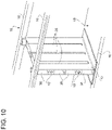
- the vehicle battery pack 3 comprises a support structure 15 comprising, in turn, at least to elongated perimeter elements 16 and 18, which face one another and define, between them, a box portion BP ( figure 4 ).
- the perimeter elements are a frame 16 and a base 18. In other embodiments, they can be two frames facing one another, tubular elements, ...
- the battery pack 3 further comprises one or more bulkheads 17 arranged so as to divide the box portion BP by delimiting at least two housings, wherein the bulkheads 17 are arranged transversely to the two perimeter elements 16 and 18 facing one another.
- the frame 16 and the base 18 define two parallel planes, between which the bulkheads 17 extend crosswise (perpendicularly).
- the bulkheads 17 delimit, inside the box portion BP, three different housings.
- the battery pack 3 comprises a plurality of modules 12, which comprise, in turn, a plurality of planar electrochemical cells C, which are electrically connected and parallel both to one another and to the bulkheads 17 and are divided into at least two modules 12, in particular one module 12 for each housing. Therefore, in the non-limiting embodiment of figures 4 and 4a , there are three modules 12. In the other embodiments, there are two or more than three modules 12, if necessary arranged differently (for example, with a T, an L or a cross arrangement).
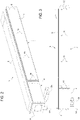
- the modules 12 each comprise, furthermore, at least two insertion plates 32 arranged at the ends of each module 12, parallel to the bulkheads 17, and configured to facilitate the insertion of each module 12 in compression into the relative housing, so that the compression remains even after the insertion.
- the modules 12 of the cells C are compressed on the outside of the housing and inserted into the latter keeping the compression. By so doing, the cells C remain compressed between the two bulkheads 17 delimiting the respective housing.
- the insertion plates 32 act as compression plates (meaning “functional compression”, as discussed more in detail below) for the cells C of the relative module 12.
- the insertion plates 32 remain interposed between each bulkhead 17 and the first or last cell C of a module 12.
- each insertion plate 32 is in contact with a respective bulkhead 17.
- the coefficient of static sliding friction between each plate 32 and the respective bulkhead 17 is smaller than 0.3, preferably smaller than 0.1. In this way, the small friction between the insertion plate 32 and the bulkhead 17 allows each module 12 to slide into the respective housing, despite the compression reaction force exerted by the compressed cells (which, in other words, tend to re-expand).
- the insertion plates 32 can be considered as "dispensable" elements, namely left inside the battery pack even though they are not made of active materials. However, advantageously though not necessarily, the insertion plates 32 are also configured to adjust the compression of the module 12 within the housing, compensating for any inaccuracies in the thickness of the plurality of cells C. In particular, the insertion plates 32 have different thicknesses. In this way, it is possible to ensure the achievement and the preservation of a desired compression of the batteries (depending on the number of cells and on their size) making up for possible production tolerances.
- the insertion plates 32 mainly comprise (namely, are made of) polytetrafluoroethylene.
- each insertion plate 32 and respective bulkhead 17 comprise guiding elements 34, 36 configured to direct the module 12 during the insertion into the respective housing, avoiding undesired rotations.
- the guiding elements are complementary elements with a shape coupling, more in particular a skate 34 and at least one respective seat 35 (or rail).
- each bulkhead comprises, for each surface in contact with a respective insertion plate 32, three parallel seats 35, which house three corresponding parallel sakes 34 obtained on the respective insertion plate 32.
- the battery pack 3 comprises a plurality of dissipating elements 20 arranged between the cells C, C', C" and configured to transfer heat towards at least one lateral surface LS of the box portion, in particular towards two opposite lateral surfaces LS.
- each dissipating element 20 comprises at least one projecting portion 21, which, together with the ones of the other dissipating elements 20, defines the lateral surface LS.
- each dissipating element 20 comprises two opposite projecting portions 21, in particular parallel to one another, which, together with the ones of the other dissipating elements 20, define the two opposite lateral surface LS.
- each module 12 comprises a plurality of energy units 19 arranged parallel to one another and enclosed between two insertion plates 32.
- the unit 19 comprises two planar pouch cells C' and C", between which the dissipating element 20 is inserted.
- Each cell C', C" comprises a pair or terminal poles TT', TT" (positive and negative poles, namely cathode and anode) extending on the same side of the cells C', C".
- terminal poles TT', TT" are arranged on opposite sides of the cells C', C".
- the dissipating element 20 comprises a main (metal) plate parallel to the main surfaces of the cells C' and C" and the projecting portions 21 on opposite sides of the unit 19, in detail on opposite sides where there are not the terminal poles TT', TT".
- the projecting portions 21 comprise a surface perpendicular to the main plate.
- the cross section of the dissipating element 20 is H-shaped.
- the cells C' and C" of a same unit 19 are connected in series, the units 19 of a same module 12 are connected in series and the different modules 12 are also connected in series.
- the unit 19 further comprises a layer 23 comprising (made of) a compensation foam parallel to the cells C', C" and preferably with the same dimensions.
- a compensation foam parallel to the cells C', C" and preferably with the same dimensions.
- said foam layer 23 is arranged in the unit 19, on the outside of the cell C'.
- the unit 19 comprises, for each cell C', C", a peripheral thermal protection 24 configured to protect the edges of the cell C', C" and the relative terminal poles TT', TT", conveying the heat generated by the cell towards the dissipating element 20.
- each peripheral protection comprises (is made of) a polyimide film, preferably Kapton. More precisely, the thermal protections 24 are arranged between the dissipating element 20 and the cells C', C".
- the main plate of the dissipating element 20 has two flat faces, against which a protective film layer 26 (in detail, made of isofoil) rests.
- the unit 19 further comprises a further protective layer between two adjacent units 19, namely a separation film 26 (also made of isofoil).
- the unit 19 further comprises a plastic material support 27 configured to support the terminal poles TT', TT" and on which they are connected in series.
- a plastic material support 27 configured to support the terminal poles TT', TT" and on which they are connected in series.
- both terminal poles TT', TT are bent in the same direction
- the terminal poles TT', TT are bent with an S shape, so as to connect each intermediate cell C" both to the preceding and to the following cell.
- the support 27 has a passage 28, which permits an interconnection between the cells C', C".
- the support 27 has a separation 29, which prevents the poles of the two adjacent cells C', C" from coming into contact.
- the support 27 has fixing means 30, which allow said support to be fixed to channels 22 obtained on the dissipating element 20.
- the unit 19 further comprises one or more connection plates 31 configured to connect and protect the connection between two terminal poles TT', TT"
- each module 12 comprises a plurality of units 19 arranged parallel to one another, at whose ends there are the two insertion plates 32.
- each insertion plate and the cells C namely the units 19, there are two layers 33 of thermally insulating material. In this way, the temperature remains even along the module, thus preventing the outer cells from dissipating more heat towards the support structure (and the bulkheads 17) compared to the inner cells.
- the insertion plates 32 also help increase the thermal insulation of the module 12.
- the battery pack 3 comprises at least one cooling panel 11 arranged in the area of said at least one lateral surface LS and configured to be fixed to the support structure 15 so as to dissipate the heat transmitted by the dissipating elements 20.
- the battery pack 3 comprises two cooling panels 11 arranged on the two opposite lateral surfaces LS. More in particular, the cooling panels 11 are mounted on board the support structure 15, in particular on board the bulkheads 17, by means of fixing elements 10, 10'. The cooling panels 11 being configured to dissipate the heat provided by the dissipating elements 20.
- the battery pack 3 comprises one single cooling panel 11 for several modules 12, in particular for each lateral surface LS.
- thermo-convective paste is present between each cooling panel 11 and the respective lateral surface. In this way, the transmission of heat between the projecting portions 21 of the dissipating elements 20 and the cooling panels 11 is further increased.
- the panels 11 are mounted to the support structure 15, in particular to the perimeter elements 16, 17, so as to hermetically seal the lateral surface or surfaces LS.
- a sealing fluid is applied onto the lateral perimeter of the section 7 or onto the perimeter of the panels 11.
- the battery pack 3 comprises an upper opening, which is hermetically closed by a cover element 9.
- the battery pack 3 further comprises at least one removable busbar BB, wherein the busbar BB is the first removable element once the cover element has been removed. In this way, maintenance operations are facilitated, easily cutting current to the control system 8.
- a hermetic seal of the battery pack 3 is ensured, in particular an IP67 seal, protecting the cells C from liquids, dusts, fumes present inside the engine compartment 4. Furthermore, advantageously, said hermetic seal allows the air flows inside the battery pack 3 to be adjusted with utmost precision, through the venting valve CC, which becomes an obligated passage.
- the bulkheads 17 comprise channels 36 configured to lighten the support structure 15.
- the support structure 15 and/or the bulkheads are made of aluminium or of a composite material (for example, carbon fibre).
- the bulkheads 17 are configured to connect the frame 16 and the base 17.
- the busbar BB has an elongated shape and runs, under the cover element 9, along the entire length of the section 7, so as to connect the series of cells C to the terminals T of the control system 8.
- the busbar BB comprises, for example at half its length, a current sensor so as to monitor more accurately the flow of current through it and free space inside the section 6.
- a control unit 13 is provided, which can be installed in a battery pack 3 comprising at least one module 12 provided with a plurality of electrochemical cells C carried on board a support structure 15 of the vehicle battery pack 3.
- the unit 13 can be installed in the battery pack 3 according to the description above.
- control unit 13 can be installed on board the support structure 15 (in particular, above the terminal poles TT', TT").
- control unit 13 comprises a planar support substrate 37 comprising (made of) an at least partially insulating material. Furthermore, the control unit 13 comprises a plurality of sensor elements 14 configured to control the operating parameters of the electrochemical cells C of the module 12 (voltage, temperature, ).
- At least part of the sensors elements 14 are arranged, on the support substrate 37, in single rows so as to be each positioned, once the unit 13 is installed on board the vehicle battery pack 3, in the area of a respective terminal pole TT', TT" of each electrochemical cell C', C".
- the sensor elements 14 comprise at least one voltage sensing device TS, which comprises at least two conductor and elastically deformable contact elements 39, which are configured to be, in use, elastically compressed between the planar support substrate 37 and the respective terminal pole TT', TT" ( figure 13 ), contacting the latter in two different points.
- the unit 13 can be installed eliminating the need for a large number of wired connections and facilitating the assembly.
- the contact elements 39 are (entirely) interposed and compressed (squashed) between the planar support substrate 37 and the respective terminal pole TT', TT" ( figure 13 ) of each electrochemical cell C', C".
- the contact elements 39 are (entirely) interposed and compressed (squashed) between the planar support substrate 37 and the respective terminal pole TT', TT" ( figure 13 ) of each electrochemical cell C', C".
- the contact elements 39 extend from the planar substrate 37 (in detail, from a lower face thereof) downwards, contacting the terminal poles TT', TT" and holding the contact through compression.
- the contact elements 39 are V-shaped with two contiguous segments, a first segment being parallel and fixed to the planar substrate 37, whereas a second segment diverges from the planar substrate 37 itself, in particular towards the outside of the terminal pole TT', TT" ( figure 13 ).
- each sensor element 14 further comprises a temperature sensor TS configured to detect the temperature in the area of the respective terminal pole TT', TT".
- the temperature sensors TS are arranged in two single rows.
- the temperature sensor is a wired (and remote) thermistor of the NTC type.
- the temperature sensor comprises a remote NTC connector 38, to which probes are wired, which are arranged as close as possible to the cell C', C".
- the temperature sensor is a thermistor 42 of the NTC SMD type with a thermal gap, configured to detect the thermal conduction of the respective terminal pole TT', TT".
- the temperature sensor TS is an infrared sensor 40 arranged on board the planar substrate 37 on the same (lower) face as the contact elements (39) and configured to face the respective terminal pole TT', TT", so as to point a respective infrared light beam 41 at it in order to measure the temperature thereof.
- the light beam 41 is a beam with a conical shape ( figure 13 ).
- the infrared sensor 40 is arranged between the two contact elements 39 associated with the respective terminal pole TT', TT" (in detail, along a same straight line).
- the second segment of the contact elements 39 diverges from the planar substrate 37 in an opposite direction relative to the sensor 40. In this way, the elements 39 follow the conical shape of the light beam 41 and reduce the risk of wrong measurements.
- the battery pack 3 comprises at least one unit 13 for each module 12.
- the units 13 are arranged on a same plane between the terminal poles TT', TT" of the cells C', C" of the units 19 and the closing element 9 (or the busbar BB).
- a road vehicle 1 comprising a battery pack 3 of the type described so far.
- a method to assemble a battery pack 3. comprises the steps of:
- the insertion is accomplished with the aid of the two insertion plates 32 arranged at the ends of the module 12 under compression, parallel to the bulkheads 17, wherein the insertion plates 32 facilitate the insertion of the module 12 under compression into the relative housing, so that compression remains even after insertion. More in particular, the insertion plates 32 are inserted into the relative housing together with the module 12 and remain inside the battery pack 3 even after the insertion.
- the compression remaining after the insertion depends on the type of cells C (for example, lithium-ion, lithium metal, solid-state, etc.) and ranges from 0.5 to 25 bar. In particular, from 0.5 bar to 5 bar for cells C with liquid electrolytes and from 2.5 to 25 bar for solid-state cells C.
- type of cells C for example, lithium-ion, lithium metal, solid-state, etc.
- ranges from 0.5 to 25 bar. In particular, from 0.5 bar to 5 bar for cells C with liquid electrolytes and from 2.5 to 25 bar for solid-state cells C.
- the compression force CF is applied to the insertion plates 32 and/or to portions of the supports 27 arranged in the area of the plurality of cells C (and of the units 19), on the opposite side relative to the housing.
- the aforesaid portions are arranged between the terminal poles TT', TT" of the plurality of cells C, which are arranged in the two parallel rows.
- the method comprises the further step of applying a sealing fluid along the elongated perimeter elements so as to surround the two opposite lateral surfaces LS of the box portion BP and hermetically seal said lateral surfaces LS with the same number of cooling panels 11 arranged in the area of the lateral surfaces.
- the method comprises the further step of applying a sealing fluid along the elongated perimeter elements in the area of at least one upper opening of the box portion BP and hermetically closing said upper opening with the cover element 9.
- the method further entails installing one or more units 13 according to the description above, so that each sensor element 14 is in the area of a respective terminal pole TT', TT" and so that said at least two conductor and elastically deformable contact elements 39 are elastically compressed between the planar support substrate 37 and the respective terminal pole TT', TT", contacting the latter in two different points.
- the invention offers many advantages.
- a traditional battery pack which comprises several concentric housings, one for each module and one for the interconnection between the modules and their positioning inside the frame.
- the invention facilitates the assembly of the battery pack, anyway ensuring a sufficient heat dissipation.
- a further advantage of the invention lies in the possibility of adjusting the compression inside the housing by changing the thickness of the insertion plates.
- the invention offers a battery pack with an easier maintenance, since the risk of current discharges is reduced, facilitating the removal of the busbar.
- the invention allows manufacturers to quickly and easily install the control units 13, eliminating useless wirings and further lightening the structure.
- the invention allows the temperature of the terminal poles of the cells to be monitored without necessarily having to contact them, thus preserving them.
Landscapes
- Chemical & Material Sciences (AREA)
- Chemical Kinetics & Catalysis (AREA)
- Electrochemistry (AREA)
- General Chemical & Material Sciences (AREA)
- Engineering & Computer Science (AREA)
- Manufacturing & Machinery (AREA)
- Mechanical Engineering (AREA)
- Transportation (AREA)
- Aviation & Aerospace Engineering (AREA)
- Life Sciences & Earth Sciences (AREA)
- Sustainable Development (AREA)
- Sustainable Energy (AREA)
- Power Engineering (AREA)
- Combustion & Propulsion (AREA)
- Battery Mounting, Suspending (AREA)
- Automobile Manufacture Line, Endless Track Vehicle, Trailer (AREA)
- Arrangement Or Mounting Of Propulsion Units For Vehicles (AREA)
- Secondary Cells (AREA)
- Connection Of Batteries Or Terminals (AREA)
Applications Claiming Priority (1)
| Application Number | Priority Date | Filing Date | Title |
|---|---|---|---|
| IT102021000012623A IT202100012623A1 (it) | 2021-05-17 | 2021-05-17 | Pacco batteria veicolare e relativo metodo di assemblaggio |
Publications (1)
| Publication Number | Publication Date |
|---|---|
| EP4092794A1 true EP4092794A1 (fr) | 2022-11-23 |
Family
ID=77317273
Family Applications (1)
| Application Number | Title | Priority Date | Filing Date |
|---|---|---|---|
| EP22172722.5A Pending EP4092794A1 (fr) | 2021-05-17 | 2022-05-11 | Bloc-batterie de véhicule et procédé d'assemblage associé |
Country Status (5)
| Country | Link |
|---|---|
| US (1) | US20220367960A1 (fr) |
| EP (1) | EP4092794A1 (fr) |
| JP (1) | JP2022176904A (fr) |
| CN (1) | CN115360465A (fr) |
| IT (1) | IT202100012623A1 (fr) |
Cited By (2)
| Publication number | Priority date | Publication date | Assignee | Title |
|---|---|---|---|---|
| IT202300014934A1 (it) * | 2023-07-17 | 2025-01-17 | Ferrari Spa | Pacco batteria per un veicolo stradale a propulsione elettrica e veicolo stradale a propulsione elettrica dotato di tale pacco batteria |
| WO2025016794A1 (fr) * | 2023-07-18 | 2025-01-23 | Valeo Systemes Thermiques | Ensemble de régulation thermique, notamment pour véhicule automobile, et système de régulation thermique correspondant |
Families Citing this family (2)
| Publication number | Priority date | Publication date | Assignee | Title |
|---|---|---|---|---|
| US20230049782A1 (en) * | 2021-08-10 | 2023-02-16 | The University Of Chicago | Anisotropic thermal conductors |
| CN116154396B (zh) * | 2023-03-31 | 2025-01-21 | 蜂巢能源科技股份有限公司 | 支撑结构、电芯模组及电池系统 |
Citations (7)
| Publication number | Priority date | Publication date | Assignee | Title |
|---|---|---|---|---|
| WO2010081704A2 (fr) * | 2009-01-19 | 2010-07-22 | Li-Tec Battery Gmbh | Dispositif d'accumulation d'énergie électrochimique |
| DE102018210444B3 (de) * | 2018-06-27 | 2019-05-09 | Bayerische Motoren Werke Aktiengesellschaft | Hochvoltbatterie für ein Kraftfahrzeug sowie Kraftfahrzeug |
| US20190165408A1 (en) * | 2017-11-27 | 2019-05-30 | Aurora Flight Sciences Corporation | System, method, and apparatus for battery cell-stack compression |
| DE102019108639A1 (de) * | 2018-04-05 | 2019-10-10 | Ford Global Technologies, Llc | Verfahren und Batteriebaugruppe für ein elektrifiziertes Fahrzeug |
| EP3584877A1 (fr) * | 2018-05-16 | 2019-12-25 | Samsung SDI Co., Ltd. | Bloc batterie comprenant un profilé de cadre avec des éléments de circuit de refroidissement intégrés |
| EP3731300A1 (fr) * | 2017-12-19 | 2020-10-28 | SANYO Electric Co., Ltd. | Dispositif d'alimentation électrique et séparateur de dispositif d'alimentation électrique |
| CN111987248A (zh) * | 2019-05-21 | 2020-11-24 | 比亚迪股份有限公司 | 动力电池包和车辆 |
Family Cites Families (6)
| Publication number | Priority date | Publication date | Assignee | Title |
|---|---|---|---|---|
| US9558894B2 (en) * | 2011-07-08 | 2017-01-31 | Fastcap Systems Corporation | Advanced electrolyte systems and their use in energy storage devices |
| US11302973B2 (en) * | 2015-05-19 | 2022-04-12 | Ford Global Technologies, Llc | Battery assembly with multi-function structural assembly |
| DE102016125476B4 (de) * | 2016-12-22 | 2020-09-03 | Benteler Automobiltechnik Gmbh | Batterieträger für ein Elektrokraftfahrzeug mit Kühlsystem |
| JP6975385B2 (ja) * | 2018-01-12 | 2021-12-01 | トヨタ自動車株式会社 | 電池パックとその製造方法および解体方法 |
| DE102019211253A1 (de) * | 2019-07-29 | 2021-02-04 | Elringklinger Ag | Galvanische Zellen und Batteriemodule |
| CN111769229A (zh) * | 2020-07-10 | 2020-10-13 | 贾智聪 | 一种新能源汽车用车载电池存储箱 |
-
2021
- 2021-05-17 IT IT102021000012623A patent/IT202100012623A1/it unknown
-
2022
- 2022-05-04 US US17/736,754 patent/US20220367960A1/en active Pending
- 2022-05-11 EP EP22172722.5A patent/EP4092794A1/fr active Pending
- 2022-05-11 JP JP2022077839A patent/JP2022176904A/ja active Pending
- 2022-05-13 CN CN202210525809.0A patent/CN115360465A/zh active Pending
Patent Citations (7)
| Publication number | Priority date | Publication date | Assignee | Title |
|---|---|---|---|---|
| WO2010081704A2 (fr) * | 2009-01-19 | 2010-07-22 | Li-Tec Battery Gmbh | Dispositif d'accumulation d'énergie électrochimique |
| US20190165408A1 (en) * | 2017-11-27 | 2019-05-30 | Aurora Flight Sciences Corporation | System, method, and apparatus for battery cell-stack compression |
| EP3731300A1 (fr) * | 2017-12-19 | 2020-10-28 | SANYO Electric Co., Ltd. | Dispositif d'alimentation électrique et séparateur de dispositif d'alimentation électrique |
| DE102019108639A1 (de) * | 2018-04-05 | 2019-10-10 | Ford Global Technologies, Llc | Verfahren und Batteriebaugruppe für ein elektrifiziertes Fahrzeug |
| EP3584877A1 (fr) * | 2018-05-16 | 2019-12-25 | Samsung SDI Co., Ltd. | Bloc batterie comprenant un profilé de cadre avec des éléments de circuit de refroidissement intégrés |
| DE102018210444B3 (de) * | 2018-06-27 | 2019-05-09 | Bayerische Motoren Werke Aktiengesellschaft | Hochvoltbatterie für ein Kraftfahrzeug sowie Kraftfahrzeug |
| CN111987248A (zh) * | 2019-05-21 | 2020-11-24 | 比亚迪股份有限公司 | 动力电池包和车辆 |
Cited By (4)
| Publication number | Priority date | Publication date | Assignee | Title |
|---|---|---|---|---|
| IT202300014934A1 (it) * | 2023-07-17 | 2025-01-17 | Ferrari Spa | Pacco batteria per un veicolo stradale a propulsione elettrica e veicolo stradale a propulsione elettrica dotato di tale pacco batteria |
| EP4496091A1 (fr) * | 2023-07-17 | 2025-01-22 | FERRARI S.p.A. | Bloc-batterie pour véhicule routier à propulsion électrique et véhicule routier à propulsion électrique équipé d'un tel bloc-batterie |
| WO2025016794A1 (fr) * | 2023-07-18 | 2025-01-23 | Valeo Systemes Thermiques | Ensemble de régulation thermique, notamment pour véhicule automobile, et système de régulation thermique correspondant |
| FR3151393A1 (fr) * | 2023-07-18 | 2025-01-24 | Valeo Systemes Thermiques | Ensemble de régulation thermique, notamment pour véhicule automobile, et système de régulation thermique correspondant |
Also Published As
| Publication number | Publication date |
|---|---|
| US20220367960A1 (en) | 2022-11-17 |
| CN115360465A (zh) | 2022-11-18 |
| IT202100012623A1 (it) | 2022-11-17 |
| JP2022176904A (ja) | 2022-11-30 |
Similar Documents
| Publication | Publication Date | Title |
|---|---|---|
| EP4092794A1 (fr) | Bloc-batterie de véhicule et procédé d'assemblage associé | |
| US12438207B2 (en) | Control unit, vehicular battery pack and relative assembly method | |
| US8299801B2 (en) | Car battery system | |
| KR101174045B1 (ko) | 배터리 팩 및 이를 구비하는 배터리 팩 조립체 | |
| US20230104209A1 (en) | Cell separating device for spacing two adjacent battery cells in a battery module, and battery module, and motor vehicle | |
| KR100896131B1 (ko) | 중대형 전지모듈 | |
| US20160104873A1 (en) | Battery pack system and method for fabrication thereof | |
| US20200220126A1 (en) | Electricity storage module and manufacturing method of electricity storage module | |
| CN101662054A (zh) | 电池系统 | |
| EP4092811A1 (fr) | Unité de commande, bloc-batterie de véhicule et procédé d'assemblage associé | |
| US10673040B2 (en) | Vehicular battery pack | |
| CN116830370A (zh) | 用于电池壳体的隔壁组件、电池和车辆 | |
| JP7042174B2 (ja) | バッテリパック | |
| EP3528313B1 (fr) | Bloc-batterie de véhicule | |
| CN113451695B (zh) | 电池模组和电动车辆 | |
| EP3528311B1 (fr) | Bloc-batterie de véhicule | |
| US12583336B2 (en) | Battery module and electric vehicle | |
| EP4496091B1 (fr) | Bloc-batterie pour véhicule routier à propulsion électrique et véhicule routier à propulsion électrique équipé d'un tel bloc-batterie | |
| EP3528315B1 (fr) | Bloc-batterie de véhicule | |
| EP4525144A1 (fr) | Bloc-batterie |
Legal Events
| Date | Code | Title | Description |
|---|---|---|---|
| PUAI | Public reference made under article 153(3) epc to a published international application that has entered the european phase |
Free format text: ORIGINAL CODE: 0009012 |
|
| STAA | Information on the status of an ep patent application or granted ep patent |
Free format text: STATUS: THE APPLICATION HAS BEEN PUBLISHED |
|
| AK | Designated contracting states |
Kind code of ref document: A1 Designated state(s): AL AT BE BG CH CY CZ DE DK EE ES FI FR GB GR HR HU IE IS IT LI LT LU LV MC MK MT NL NO PL PT RO RS SE SI SK SM TR |
|
| STAA | Information on the status of an ep patent application or granted ep patent |
Free format text: STATUS: REQUEST FOR EXAMINATION WAS MADE |
|
| 17P | Request for examination filed |
Effective date: 20230523 |
|
| RBV | Designated contracting states (corrected) |
Designated state(s): AL AT BE BG CH CY CZ DE DK EE ES FI FR GB GR HR HU IE IS IT LI LT LU LV MC MK MT NL NO PL PT RO RS SE SI SK SM TR |
|
| P01 | Opt-out of the competence of the unified patent court (upc) registered |
Effective date: 20230525 |
|
| STAA | Information on the status of an ep patent application or granted ep patent |
Free format text: STATUS: EXAMINATION IS IN PROGRESS |
|
| 17Q | First examination report despatched |
Effective date: 20250407 |