EP4093096A1 - Procédé, appareil et dispositif de détermination d'informations, et support de stockage lisible par ordinateur - Google Patents
Procédé, appareil et dispositif de détermination d'informations, et support de stockage lisible par ordinateur Download PDFInfo
- Publication number
- EP4093096A1 EP4093096A1 EP20913394.1A EP20913394A EP4093096A1 EP 4093096 A1 EP4093096 A1 EP 4093096A1 EP 20913394 A EP20913394 A EP 20913394A EP 4093096 A1 EP4093096 A1 EP 4093096A1
- Authority
- EP
- European Patent Office
- Prior art keywords
- timer
- terminal
- sidelink
- measurement result
- channel measurement
- Prior art date
- Legal status (The legal status is an assumption and is not a legal conclusion. Google has not performed a legal analysis and makes no representation as to the accuracy of the status listed.)
- Pending
Links
Images



Classifications
-
- H—ELECTRICITY
- H04—ELECTRIC COMMUNICATION TECHNIQUE
- H04W—WIRELESS COMMUNICATION NETWORKS
- H04W76/00—Connection management
- H04W76/20—Manipulation of established connections
- H04W76/23—Manipulation of direct-mode connections
-
- H—ELECTRICITY
- H04—ELECTRIC COMMUNICATION TECHNIQUE
- H04W—WIRELESS COMMUNICATION NETWORKS
- H04W40/00—Communication routing or communication path finding
- H04W40/02—Communication route or path selection, e.g. power-based or shortest path routing
- H04W40/22—Communication route or path selection, e.g. power-based or shortest path routing using selective relaying for reaching a BTS [Base Transceiver Station] or an access point
-
- H—ELECTRICITY
- H04—ELECTRIC COMMUNICATION TECHNIQUE
- H04W—WIRELESS COMMUNICATION NETWORKS
- H04W52/00—Power management, e.g. Transmission Power Control [TPC] or power classes
- H04W52/02—Power saving arrangements
- H04W52/0209—Power saving arrangements in terminal devices
- H04W52/0225—Power saving arrangements in terminal devices using monitoring of external events, e.g. the presence of a signal
-
- H—ELECTRICITY
- H04—ELECTRIC COMMUNICATION TECHNIQUE
- H04W—WIRELESS COMMUNICATION NETWORKS
- H04W52/00—Power management, e.g. Transmission Power Control [TPC] or power classes
- H04W52/02—Power saving arrangements
- H04W52/0209—Power saving arrangements in terminal devices
- H04W52/0225—Power saving arrangements in terminal devices using monitoring of external events, e.g. the presence of a signal
- H04W52/0229—Power saving arrangements in terminal devices using monitoring of external events, e.g. the presence of a signal where the received signal is a wanted signal
-
- H—ELECTRICITY
- H04—ELECTRIC COMMUNICATION TECHNIQUE
- H04W—WIRELESS COMMUNICATION NETWORKS
- H04W52/00—Power management, e.g. Transmission Power Control [TPC] or power classes
- H04W52/02—Power saving arrangements
- H04W52/0209—Power saving arrangements in terminal devices
- H04W52/0225—Power saving arrangements in terminal devices using monitoring of external events, e.g. the presence of a signal
- H04W52/0245—Power saving arrangements in terminal devices using monitoring of external events, e.g. the presence of a signal according to signal strength
-
- H—ELECTRICITY
- H04—ELECTRIC COMMUNICATION TECHNIQUE
- H04W—WIRELESS COMMUNICATION NETWORKS
- H04W76/00—Connection management
- H04W76/20—Manipulation of established connections
- H04W76/27—Transitions between radio resource control [RRC] states
-
- H—ELECTRICITY
- H04—ELECTRIC COMMUNICATION TECHNIQUE
- H04W—WIRELESS COMMUNICATION NETWORKS
- H04W76/00—Connection management
- H04W76/20—Manipulation of established connections
- H04W76/28—Discontinuous transmission [DTX]; Discontinuous reception [DRX]
-
- H—ELECTRICITY
- H04—ELECTRIC COMMUNICATION TECHNIQUE
- H04W—WIRELESS COMMUNICATION NETWORKS
- H04W28/00—Network traffic management; Network resource management
- H04W28/02—Traffic management, e.g. flow control or congestion control
- H04W28/0231—Traffic management, e.g. flow control or congestion control based on communication conditions
-
- H—ELECTRICITY
- H04—ELECTRIC COMMUNICATION TECHNIQUE
- H04W—WIRELESS COMMUNICATION NETWORKS
- H04W48/00—Access restriction; Network selection; Access point selection
- H04W48/16—Discovering, processing access restriction or access information
-
- H—ELECTRICITY
- H04—ELECTRIC COMMUNICATION TECHNIQUE
- H04W—WIRELESS COMMUNICATION NETWORKS
- H04W52/00—Power management, e.g. Transmission Power Control [TPC] or power classes
- H04W52/02—Power saving arrangements
- H04W52/0209—Power saving arrangements in terminal devices
- H04W52/0212—Power saving arrangements in terminal devices managed by the network, e.g. network or access point is leader and terminal is follower
- H04W52/0216—Power saving arrangements in terminal devices managed by the network, e.g. network or access point is leader and terminal is follower using a pre-established activity schedule, e.g. traffic indication frame
-
- H—ELECTRICITY
- H04—ELECTRIC COMMUNICATION TECHNIQUE
- H04W—WIRELESS COMMUNICATION NETWORKS
- H04W92/00—Interfaces specially adapted for wireless communication networks
- H04W92/16—Interfaces between hierarchically similar devices
- H04W92/18—Interfaces between hierarchically similar devices between terminal devices
-
- Y—GENERAL TAGGING OF NEW TECHNOLOGICAL DEVELOPMENTS; GENERAL TAGGING OF CROSS-SECTIONAL TECHNOLOGIES SPANNING OVER SEVERAL SECTIONS OF THE IPC; TECHNICAL SUBJECTS COVERED BY FORMER USPC CROSS-REFERENCE ART COLLECTIONS [XRACs] AND DIGESTS
- Y02—TECHNOLOGIES OR APPLICATIONS FOR MITIGATION OR ADAPTATION AGAINST CLIMATE CHANGE
- Y02D—CLIMATE CHANGE MITIGATION TECHNOLOGIES IN INFORMATION AND COMMUNICATION TECHNOLOGIES [ICT], I.E. INFORMATION AND COMMUNICATION TECHNOLOGIES AIMING AT THE REDUCTION OF THEIR OWN ENERGY USE
- Y02D30/00—Reducing energy consumption in communication networks
- Y02D30/70—Reducing energy consumption in communication networks in wireless communication networks
Definitions
- the present disclosure relates to the field of communications technology, in particular to an information determination method, device, apparatus and a computer readable storage medium.
- V2X Vehicle-to-everything
- V2X In the Long Term Evolution (LTE) V2X technology in the related art, broadcast communications on a PC5 interface (also called a sidelink in the protocol) for data transmission between UE (UE) and UE can already support the transmission of basic services based on the road safety.
- V2X services include vehicle-to-vehicle (V2V), vehicle-to-infrastructure (V2I), and vehicle-to-pedestrian (V2P) communications.
- V2V vehicle-to-vehicle
- V2I vehicle-to-infrastructure
- V2P vehicle-to-pedestrian
- New Radio (NR) V2X has emerged some new application scenarios, such as: vehicle formation, advanced driving, sensor information sharing, and remote control and other applications, and unicast, multicast and broadcast services are supported at the same time.
- DRX discontinuous reception
- Embodiments of the present disclosure provide an information determination method, device, apparatus and a computer readable storage medium, so as to save the power consumption of the terminal and not reduce the communication reliability of the terminal.
- an embodiment of the present disclosure provide an information determination method, applied to a first terminal, including: obtaining a sidelink channel measurement result, and determining a timer length of a target discontinuous reception (DRX) timer according to the sidelink channel measurement result; or receiving indication information from a second terminal and determining the timer length of the target DRX timer according the indication information from the second terminal; the indication information being used to indicate the timer length of the target DRX timer; wherein the first terminal communicates with the second terminal through a sidelink.
- DRX discontinuous reception
- the receiving the indication information from a second terminal includes: receiving a sidelink radio resource control (RRC) signaling or a sidelink media access control (MAC) control element (CE) sent by the second terminal, the sidelink RRC signaling or the sidelink MAC CE being used to indicate the timer length of the target DRX timer.
- RRC radio resource control
- MAC media access control
- the obtaining a sidelink channel measurement result includes at least one of the following: obtaining a sidelink channel measurement result of the first terminal; obtaining a sidelink channel measurement result sent by the second terminal; or obtaining a sidelink channel measurement result sent by a network side device.
- the obtaining a sidelink channel measurement result sent by the second terminal includes: receiving a sidelink RRC signaling or a sidelink MAC CE sent by the second terminal, the sidelink RRC signaling or the sidelink MAC CE including the sidelink channel measurement result.
- the sidelink RRC signaling or the sidelink MAC CE further includes at least one of the following: a source layer L2 identifier, a destination L2 identifier, a sidelink radio barrier (SLRB) identifier, or a logic channel ID (LCID).
- a source layer L2 identifier a source layer L2 identifier
- a destination L2 identifier a destination L2 identifier
- a sidelink radio barrier (SLRB) identifier a logic channel ID (LCID).
- LCID logic channel ID
- the obtaining a sidelink channel measurement result sent by the network side device includes: obtaining an RRC signaling or a MAC CE sent by the network side device, wherein the RRC signaling or the MAC CE includes the sidelink channel measurement result.
- the RRC signaling or the MAC CE further includes at least one of the following: a source layer L2 identifier, a destination L2 identifier, an SLRB identifier, or an LCID.
- the determining the timer length of the target DRX timer according to the sidelink channel measurement result includes: obtaining a corresponding relationship between the sidelink channel measurement result and the timer length of the DRX timer; determining the timer length of the target DRX timer according the corresponding relationship and the sidelink channel measurement result.
- the determining the timer length of the target DRX timer according to the sidelink channel measurement result includes: obtaining a corresponding relationship among the sidelink channel measurement result, quality of service (QoS) and the timer length of the DRX timer; and determining the timer length of the target DRX timer according to the corresponding relationship, QoS required by a current service and the sidelink channel measurement result.
- QoS quality of service
- the corresponding relationship is configured by the network side device, or the corresponding relationship is pre-configured in the first terminal.
- the corresponding relationship is configured by the network side device through a dedicated RRC signaling or a broadcast RRC signaling.
- the sidelink channel measurement result includes one or more of channel state information and a channel congestion degree;
- the channel state information includes one or more of the following: Channel State Information (CSI), Rand Indication (RI), Channel Quality Indicator (CQI), Signal to Interference plus Noise Ratio (SINR), Reference Signal Receiving Power (RSRP), Reference Signal Receiving Quality (RSRQ), Received Signal Strength Indication (RSSI), Block Error Rate, Bit Error Rate, and Sounding Reference Signal (SRS);
- the channel congestion degree includes one or more of the following: a Channel Busy Ratio (CBR) threshold, and a channel occupancy ratio (CR).
- CBR Channel Busy Ratio
- CR channel occupancy ratio
- the target DRX timer includes one or more of the following: Onduration timer, Short DRX cycle Timer, Long DRX cycle Timer, Inactivity Timer, RTT Timer, Retransmission Timer.
- an embodiment of the present disclosure provides an information determination method, applied to a second terminal, including: sending a sidelink channel measurement result to a first terminal, so that the first terminal determines a timer length of a target DRX timer according to the sidelink channel measurement result; or sending indication information to the first terminal, wherein the indication information is used to indicate the timer length of the target DRX timer; or sending a reference signal to the first terminal, so that the first terminal determines the sidelink channel measurement result according to the reference signal, and determine the timer length of the target DRX timer according to the sidelink channel measurement result; wherein the second terminal communicates with the first terminal through a sidelink.
- the sending a sidelink channel measurement result to a first terminal includes: sending a sidelink RRC signaling or a sidelink MAC CE to the first terminal, the sidelink RRC signaling or the sidelink MAC CE including the sidelink channel measurement result.
- the sending indication information to the first terminal includes: obtaining a corresponding relationship between the sidelink channel measurement result and the timer length of the DRX timer; determining the timer length of the target DRX timer according to the corresponding relationship and the sidelink channel measurement result; sending the indication information to the first terminal, wherein the indication information is used to indicate the timer length of the target DRX timer.
- the sending indication information to the first terminal includes: obtaining a corresponding relationship among the sidelink channel measurement result, QoS and the timer length of the DRX timer; determining the timer length of the target DRX timer according the corresponding relationship, QoS required by a current service and the sidelink channel measurement result; sending the indication information to the first terminal, wherein the indication information is used to indicate the timer length of the target DRX timer.
- the sending indication information to the first terminal includes: sending a sidelink RRC signaling or a sidelink MAC CE to the first terminal, wherein the sidelink RRC signaling or the sidelink MAC CE is used to indicate the timer length of the target DRX timer.
- the sidelink RRC signaling or the sidelink MAC CE further includes at least one of the following: a source layer L2 identifier, a destination L2 identifier, an SLRB identifier, or an LCID.
- the corresponding relationship is configured by the network side device, or the corresponding relationship is pre-configured in the second terminal.
- the corresponding relationship is configured by the network side device through a dedicated RRC signaling or a broadcast RRC signaling.
- the sidelink channel measurement result includes one or both of channel state information and a channel congestion degree;
- the channel state information includes one or more of the following: CSI, RI, CQI, SINR, RSRP, RSRQ, RSSI, block error rate, bit error rate and SRS;
- the channel congestion degree includes one or more of the following: a CBR threshold, a CR.
- the target DRX timer includes one or more of the following: Onduration timer, Short DRX cycle Timer, Long DRX cycle Timer, Inactivity Timer, RTT Timer, Retransmission Timer.
- an embodiment of the present disclosure provides an information determination method, applied to a network side device, including: sending a sidelink channel measurement result to a first terminal, so that the first terminal determines a timer length of a target DRX timer according to the sidelink channel measurement result.
- the method further includes at least one of the following: sending a corresponding relationship between the sidelink channel measurement result and the timer length of the DRX timer to the first terminal and/or a second terminal; sending a corresponding relationship among the sidelink channel measurement result, QoS and the timer length of the DRX timer to the first terminal and/or the second terminal.
- an embodiment of the present disclosure provides an information determination device, applied to a first terminal, including: a first obtaining module, configured to obtain a sidelink channel measurement result, and determining a timer length of a target discontinuous reception (DRX) timer according to the sidelink channel measurement result; or a first receiving module, configured to receive indication information from a second terminal and determining the timer length of the target DRX timer according the indication information from the second terminal; the indication information being used to indicate the timer length of the target DRX timer; wherein the first terminal communicates with the second terminal through a sidelink.
- a first obtaining module configured to obtain a sidelink channel measurement result, and determining a timer length of a target discontinuous reception (DRX) timer according to the sidelink channel measurement result
- a first receiving module configured to receive indication information from a second terminal and determining the timer length of the target DRX timer according the indication information from the second terminal; the indication information being used to indicate the timer length of the target DRX time
- the first receiving module is specifically configured to receive a sidelink radio resource control (RRC) signaling or a sidelink media access control (MAC) control element (CE) sent by the second terminal, the sidelink RRC signaling or the sidelink MAC CE being used to indicate the timer length of the target DRX timer.
- RRC radio resource control
- MAC media access control
- the first obtaining module is specifically configured to execute at least one of the following: obtaining a sidelink channel measurement result of the first terminal; obtaining a sidelink channel measurement result sent by the second terminal; or obtaining a sidelink channel measurement result sent by a network side device.
- the first obtaining module is specifically configured to receive a sidelink RRC signaling or a sidelink MAC CE sent by the second terminal, the sidelink RRC signaling or the sidelink MAC CE including the sidelink channel measurement result; or, the first obtaining module is specifically configured to obtain an RRC signaling or a MAC CE sent by the network side device, wherein the RRC signaling or the MAC CE includes the sidelink channel measurement result.
- the first obtaining module includes: a first obtaining sub-module, configured to obtain a corresponding relationship between the sidelink channel measurement result and the timer length of the DRX timer; a first determination sub-module, configured to determine the timer length of the target DRX timer according the corresponding relationship and the sidelink channel measurement result; or, the first obtaining module includes: a second obtaining submodule, configured to obtain a corresponding relationship among the sidelink channel measurement result, quality of service (QoS) and the timer length of the DRX timer; a second determination submodule, configured to determine the timer length of the target DRX timer according to the corresponding relationship, QoS required by a current service and the sidelink channel measurement result.
- QoS quality of service
- an embodiment of the present disclosure provides an information determination device, applied to a second terminal, including: a first sending module, configured to send a sidelink channel measurement result to a first terminal, so that the first terminal determines a timer length of a target DRX timer according to the sidelink channel measurement result; or a second sending module, configured to send indication information to the first terminal, wherein the indication information is used to indicate the timer length of the target DRX timer; or a third sending module, configured to send a reference signal to the first terminal, so that the first terminal determines the sidelink channel measurement result according to the reference signal, and determine the timer length of the target DRX timer according to the sidelink channel measurement result; wherein the second terminal communicates with the first terminal through a sidelink.
- the first sending module is specifically configured to send a sidelink RRC signaling or a sidelink MAC CE to the first terminal, the sidelink RRC signaling or the sidelink MAC CE including the sidelink channel measurement result.
- the second sending module includes: a first obtaining sub-module, configured to obtain a corresponding relationship between the sidelink channel measurement result and the timer length of the DRX timer; a first determination sub-module, configured to determine the timer length of the target DRX timer according to the corresponding relationship and the sidelink channel measurement result; a first sending submodule, configured to send the indication information to the first terminal, wherein the indication information is used to indicate the timer length of the target DRX timer; or, the second sending module includes: a second obtaining submodule, configured to obtain a corresponding relationship among the sidelink channel measurement result, QoS and the timer length of the DRX timer; a second determination submodule, configured to determine the timer length of the target DRX timer according the corresponding relationship, QoS required by a current service and the sidelink channel measurement result; and a second sending submodule, configured to send the indication information to the first terminal, wherein the indication information is used to indicate the timer
- an embodiment of the present disclosure provides an information determination device, applied to a network side device, including: a first sending module, configured to send a sidelink channel measurement result to a first terminal, so that the first terminal determines a timer length of a target DRX timer according to the sidelink channel measurement result.
- the information determination device further includess any one or both of the following modules: a second sending module, configured to send a corresponding relationship between the sidelink channel measurement result and the timer length of the DRX timer to the first terminal and/or a second terminal; a third sending module, configured to send a corresponding relationship among the sidelink channel measurement result, QoS and the timer length of the DRX timer to the first terminal and/or the second terminal.
- a second sending module configured to send a corresponding relationship between the sidelink channel measurement result and the timer length of the DRX timer to the first terminal and/or a second terminal
- a third sending module configured to send a corresponding relationship among the sidelink channel measurement result, QoS and the timer length of the DRX timer to the first terminal and/or the second terminal.
- an embodiment of the present disclosure provides a communication apparatus, applied to a first terminal, including: a transceiver, a memory, a processor, and a program stored in the memory and executable on the processor; wherein the processor is configured to read the program in the memory to perform the following processes: obtaining a sidelink channel measurement result, and determining a timer length of a target discontinuous reception (DRX) timer according to the sidelink channel measurement result; or receiving indication information from a second terminal and determining the timer length of the target DRX timer according the indication information from the second terminal; the indication information being used to indicate the timer length of the target DRX timer; wherein the first terminal communicates with the second terminal through a sidelink.
- DRX discontinuous reception
- the processor is further configured to read the program in the memory to perform the following processes: receiving a sidelink radio resource control (RRC) signaling or a sidelink media access control (MAC) control element (CE) sent by the second terminal, the sidelink RRC signaling or the sidelink MAC CE being used to indicate the timer length of the target DRX timer.
- RRC radio resource control
- MAC media access control
- the processor is further configured to read the program in the memory to perform the following processes: obtaining a sidelink channel measurement result of the first terminal; obtaining a sidelink channel measurement result sent by the second terminal; or obtaining a sidelink channel measurement result sent by a network side device.
- the processor is further configured to read the program in the memory to perform the following processes: receiving a sidelink RRC signaling or a sidelink MAC CE sent by the second terminal, the sidelink RRC signaling or the sidelink MAC CE including the sidelink channel measurement result; or obtaining an RRC signaling or a MAC CE sent by the network side device, wherein the RRC signaling or the MAC CE includes the sidelink channel measurement result.
- the processor is further configured to read the program in the memory to perform the following processes: obtaining a corresponding relationship between the sidelink channel measurement result and the timer length of the DRX timer; determining the timer length of the target DRX timer according the corresponding relationship and the sidelink channel measurement result; or obtaining a corresponding relationship among the sidelink channel measurement result, quality of service (QoS) and the timer length of the DRX timer; and determining the timer length of the target DRX timer according to the corresponding relationship, QoS required by a current service and the sidelink channel measurement result.
- QoS quality of service
- an embodiment of the present disclosure provides a communication apparatus, applied to a second terminal, including: a transceiver, a memory, a processor, and a program stored on the memory and executed by the processor; wherein the processor is configured to read the program in the memory to perform the following processes: sending a sidelink channel measurement result to a first terminal, so that the first terminal determines a timer length of a target DRX timer according to the sidelink channel measurement result; or sending indication information to the first terminal, wherein the indication information is used to indicate the timer length of the target DRX timer; or sending a reference signal to the first terminal, so that the first terminal determines the sidelink channel measurement result according to the reference signal, and determine the timer length of the target DRX timer according to the sidelink channel measurement result; wherein the second terminal communicates with the first terminal through a sidelink.
- the processor is further configured to read the program in the memory to perform the following processes: sending a sidelink RRC signaling or a sidelink MAC CE to the first terminal, the sidelink RRC signaling or the sidelink MAC CE including the sidelink channel measurement result.
- the processor is further configured to read the program in the memory to perform the following processes: obtaining a corresponding relationship between the sidelink channel measurement result and the timer length of the DRX timer; determining the timer length of the target DRX timer according to the corresponding relationship and the sidelink channel measurement result; sending the indication information to the first terminal, wherein the indication information is used to indicate the timer length of the target DRX timer; or obtaining a corresponding relationship among the sidelink channel measurement result, QoS and the timer length of the DRX timer; determining the timer length of the target DRX timer according the corresponding relationship, QoS required by a current service and the sidelink channel measurement result; sending the indication information to the first terminal, wherein the indication information is used to indicate the timer length of the target DRX timer.
- an embodiment of the present disclosure provides a communication apparatus, applied to a network side device, including: a transceiver, a memory, a processor, and a program stored in the memory and executed by the processor; wherein the processor is configured to read the program in memory to perform the following processes: sending a sidelink channel measurement result to a first terminal, so that the first terminal determines a timer length of a target DRX timer according to the sidelink channel measurement result.
- the processor is further configured to read the program in the memory to perform at least one of the following: sending a corresponding relationship between the sidelink channel measurement result and the timer length of the DRX timer to the first terminal and/or a second terminal; sending a corresponding relationship among the sidelink channel measurement result, QoS and the timer length of the DRX timer to the first terminal and/or the second terminal.
- an embodiment of the present disclosure provides a computer-readable storage medium for storing a computer program, wherein the computer program is executed by a processor to implement the steps in the information determination method.
- the first terminal may determine the timer length of the target DRX timer according to the sidelink channel measurement result or the indication information of the second terminal, so that the power consumption of the first terminal can be saved, and the communication reliability of the first terminal is not reduced.
- a network side device is a device that provides wireless communication functions for the terminal, including but not limited to: gNB, radio network controller (RNC), node B (NB), base station controller (BSC), base transceiver station (BTS), home base station (for example, home evolved node B, or home node B, HNB), baseband unit (BBU), Transmitting and receiving point (TRP), transmitting point (TP), mobile switching center in 5G, etc.
- the base station in the present disclosure may also be a device that provides wireless communication functions for the terminal in other communication systems that may appear in the future.
- the terminal device includes a handheld device with a wireless connection function, a vehicle-mounted device, and the like.
- the terminal device may be: a mobile phone, a tablet computer, a notebook computer, a palmtop computer, a mobile internet device (MID), a wearable device, a virtual reality (VR) device, an augmented reality (AR) equipment, wireless terminals in industrial control, wireless terminals in self-driving, wireless terminals in smart grid, wireless terminals in transportation safety, wireless terminals in a smart city, or wireless terminals in a smart home, etc.
- LTE Long Term Evolution
- UEs In a Long Term Evolution (LTE) system, direct communication is allowed between UEs.
- the direct communication link between UEs is defined as a Sidelink, and the corresponding wireless interface is called a direct communication interface (also called a Sidelink interface);
- the cellular communication link between the network side equipment and the UE is called a Uu link, and a corresponding interface is called a Uu interface.
- UE1 and UE2 communicate directly through a Sidelink
- UE1 and UE2 communicate with a network side device through a Uu link.
- the UEs that communicate directly may all be on the network, or all of them may be off the network, or some UEs may be on the network, and some UEs may be off the network.
- the above on the network means that the UE participating in the direct communication is located within the coverage of the 3GPP base station communication carrier, and the off the network means that the UE participating in the direct communication is not within the coverage of the 3GPP base station communication carrier.
- the conventional direct communication methods include the following three:
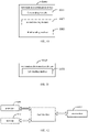
- FIG. 2 is a flowchart of an information determination method provided by an embodiment of the present disclosure, applied to a first terminal, as shown in FIG. 2 , including the following steps: Step 201: obtaining a sidelink channel measurement result, and determining a timer length of a target discontinuous reception timer according to the sidelink channel measurement result; or receiving indication information from a second terminal and determining the timer length of the target discontinuous reception timer according the indication information from the second terminal; the indication information is used to indicate the timer length of the target discontinuous reception timer.
- the first terminal communicates with the second terminal through a sidelink.
- the sidelink RRC signaling or the sidelink MAC CE sent by the second terminal may be received, wherein the sidelink RRC signaling or the sidelink MAC CE is used to indicate the timer length of the target DRX timer. That is, in this mode, the second terminal determines the timer length of the target DRX timer, and sends the timer length of the target DRX timer to the first terminal.
- the first terminal may further determine the timer length of the target DRX timer according to the obtained sidelink channel measurement result.
- the first terminal may obtain the sidelink channel measurement result in at least one of the following ways:
- the first terminal when the first terminal receives data information sent by the second terminal, since the first terminal needs to start the DRX timer to wait for the initially transmitted or retransmitted data information from the second terminal, the first terminal needs to determine the timer length of the target DRX timer according to the sidelink channel measurement result from the second terminal.
- the first terminal receives the sidelink RRC signaling or the sidelink MAC CE sent by the second terminal, and the sidelink RRC signaling or the sidelink MAC CE includes the sidelink channel measurement result.
- the sidelink RRC signaling or the sidelink MAC CE further includes at least one of the following information: a source layer L2 identifier, a destination L2 identifier, an SLRB identifier, or an LCID.
- the above-mentioned information can also be used to make the first terminal quickly distinguish that the RRC or MAC CE signaling is sent by the second terminal to the first terminal.
- the network side device determines the sidelink channel measurement result and sends the same to the first terminal.
- the first terminal obtains the RRC signaling or the MAC CE sent by the network side device, and the RRC signaling or the MAC CE includes the sidelink channel measurement result.
- the RRC signaling or MAC CE further includes at least one of the following information: a source layer L2 identifier, a destination L2 identifier, an SLRB identifier, or an LCID.
- the sidelink channel measurement result includes one or both of channel state information and channel congestion degree.
- the channel state information includes one or more of the following information:
- CSI Channel State Information
- RI Rand Indication
- CQI Channel Quality Indicator
- SINR Signal to Interference plus Noise Ratio
- RSRP Reference Signal Receiving Power
- RSRQ Reference Signal Receiving Quality
- RSSI Received Signal Strength Indication
- Block Error Rate Bit Error Rate
- SRS Sounding Reference Signal
- the channel congestion degree includes one or more of the following information: a Channel Busy Ratio (CBR) threshold, and a channel occupancy ratio (CR).
- CBR Channel Busy Ratio
- CR channel occupancy ratio
- the first terminal may determine the timer length of the target DRX timer according to the sidelink channel measurement result in the following mode.
- Mode 1 Obtaining the correspondence between the sidelink channel measurement result and the timer length of the Discontinuous Reception (DRX) Timer, and then, determining the timer length of the target DRX timer according to the corresponding relationship and the sidelink channel measurement result.
- DRX Discontinuous Reception
- the corresponding relationship is configured by the network side device, or the corresponding relationship is pre-configured in the first terminal.
- the network side device may configure the corresponding relationship through dedicated RRC signaling or broadcast RRC signaling.
- the terminal in the connected state can use the corresponding relationship between the sidelink channel measurement result and the timer length of the discontinuous reception timer configured by dedicated RRC signaling, or use the corresponding relationship between sidelink channel measurement result and the timer length of the DRX timer configured by broadcast RRC signaling, or the pre-configured corresponding relationship between the sidelink channel measurement result and the timer length of the DRX timer;
- the terminal in idle state or in the inactive state within the coverage of the network can use the corresponding relationship between the sidelink channel measurement result and the timer length of the discontinuous reception timer configured by broadcast RRC signaling, or use the pre-configured corresponding relationship between the sidelink channel measurement result and the timer length of the discontinuous reception timer.
- the terminal outside the coverage of the network can use the pre-configured correspondence between the sidelink channel measurement result and the timer length of the discontinuous reception timer.
- the correspondence between the sidelink channel measurement result and the timer length of the discontinuous reception timer may be a table, a calculation formula, or an index, etc., which is not specifically limited.
- the correspondence between the sidelink channel measurement result and the timer length of the DRX timer may be expressed as shown in Table 1 below.
- Table 1 Sidelink Channel Measurement result DRX Timer Less than or equal to the sidelink channel measurement result threshold 1 Timer1 Greater than or equal to the sidelink channel measurement result threshold 1, but Less than or equal to the sidelink channel measurement result threshold 2 Timer2 Greater than or equal to the sidelink channel measurement result threshold 2 Timer3
- the sidelink channel measurement results are CBR, CR, bit error rate, and block error rate
- the value of Timer3 is greater than the value of Timer2, the value of Timer2 is greater than the value of Timer1, and the values of Timer1, Timer2, Timer3 are greater than 0.
- Threshold 1 is less than threshold 2 and can be set according to actual needs.
- the larger the sidelink channel measurement result is the larger the corresponding DRX Timer is.
- the sidelink channel measurement results are CSI, RI, CQI, SINR, RSRP, RSRQ, RSSI
- the corresponding relationship in the form of Table 1 can also be used, the value of Timer3 is less than the value of Timer2, the value of Timer2 is less than the value of Timer1, and the values of Timer1, Timer2, and Timer3 are all greater than 0.
- Threshold 1 is less than threshold 2 and can be set according to actual needs.
- the larger the sidelink channel measurement result is the smaller the corresponding DRX Timer is.
- the larger the CSI value is, the better the channel condition is and the smaller the DRX timer is.
- Mode 2 Obtaining the corresponding relationship between the sidelink channel measurement result, QoS and the timer length of the discontinuous reception timer, and then determining the timer length of the target DRX timer according to the corresponding relationship, the Quality of Service (QoS) required by the current service, and the sidelink channel measurement result.
- QoS Quality of Service
- the corresponding relationship is configured by the network side device, or the corresponding relationship is pre-configured in the first terminal.
- the network side device may configure the corresponding relationship through dedicated RRC signaling or broadcast RRC signaling.
- the above corresponding relationship can be understood as: within the same threshold range of the sidelink channel measurement result, different timer lengths of DRX timer are determined based on different service QoS parameters, and the first terminal can select an appropriate timer length of the DRX timer according to certain principles (such as priority of services, or delay requirements of services, etc.).
- the corresponding relationship may be a table, or a calculation formula, or an index, etc., which is not specifically limited.
- Table 2-1 Sidelink channel measurement result QoS DRX Timer less than or equal to the sidelink channel measurement result threshold 1 less than or equal to the priority threshold 1; or delay threshold 1 Timer1 greater than or equal to the priority threshold 1; or delay threshold 1 Timer2 greater than or equal to the sidelink channel measurement result threshold 1, but less than or equal to the sidelink channel measurement result threshold 2 less than or equal to the priority threshold 1; or delay threshold 1 Timer3 greater than or equal to the priority threshold 1; or delay threshold 1 Timer4 greater than or equal to the sidelink channel measurement result threshold 2 less than or equal to the priority threshold 1; or delay threshold 1 Timer5 greater than or equal to the priority threshold 1; or delay threshold 1 Timer6
- the sidelink channel measurement results are CBR, CR, bit error rate, and block error rate
- the corresponding relationship in the form of Table 2-1 can be used, Timer6>Timer5>Timer4>Timer3>Timer2>Timer1, and Timer1-Timer6 are greater than 0.
- Threshold 1 is less than threshold 2 and can be set according to actual needs.
- the priority threshold 1 or the delay threshold 1 can also be set according to actual needs. In this case, the larger the sidelink channel measurement result is, the larger the corresponding DRX Timer is.
- the corresponding DRX Timer may be Timer3 or Timer4.
- the priority of the current service is less than the priority threshold 1, it can finally be determined that the timer length of the corresponding DRX Timer is Timer3.
- Table 2-1 the higher the value of the priority of a service is, the higher the priority is, and the longer timer length of the corresponding DRX timer is. In practical applications, it can also be specified that the lower the value of the priority is, the higher the priority is, and the timer length of the corresponding DRX timer is longer. Therefore, the Table 2-1 can be changed into the form of the following Table 2-2.
- Table 2-3 Sidelink channel measurement result QoS DRX Timer less than or equal to the sidelink channel measurement result threshold 1 greater than or equal to the priority threshold 1; or delay threshold 1 Timer 1 less than or equal to the priority threshold 1; or delay threshold 1 Timer2 greater than or equal to the sidelink channel measurement result threshold 1, but less than or equal to the sidelink channel measurement result threshold 2 greater than or equal to the priority threshold 1; or delay threshold 1 Timer3 less than or equal to the priority threshold 1; or delay threshold 1 Timer4 greater than or equal to the sidelink channel measurement result threshold 2 greater than or equal to the priority threshold 1; or delay threshold 1 Timer5 less than or equal to the priority threshold 1; or delay threshold 1 Timer6
- the sidelink channel measurement results are CSI, RI, CQI, SINR, RSRP, RSRQ, and RSSI
- the corresponding relationship in the form of Table 2-3 can be used.
- Timer6 ⁇ Timer5 ⁇ Timer4 ⁇ Timer3 ⁇ Timer2 ⁇ Timer1, and Timer1-Timer6 are all greater than 0.
- Threshold 1 is less than threshold 2 and can be set according to actual needs.
- the priority threshold 1 or the delay threshold 1 can also be set according to actual needs.
- Table 2-3 a higher value of priority indicates a higher priority, and the timer length of the corresponding DRX timer is longer. In practical applications, it can also be specified that the lower priority value indicates a higher priority, and the timer length of the corresponding DRX timer is longer. Therefore, the above Table 2-3 can be changed into the following Table 2-4.
- the corresponding relationship may also specify the timer timer length corresponding to each service priority, or may also specify the timer timer length corresponding to each service delay requirement.
- the target DRX timer includes one or more of the following timers:
- Onduration timer Short DRX cycle Timer, Long DRX cycle Timer, Inactivity Timer, Round Trip Time (RTT) Timer, Retransmission Timer.
- RTT Round Trip Time
- the timer lengths of the timers can also be distinguished.
- a certain rule may be preset, and the timer length of different timers may be determined according to different sidelink channel measurement results. For example, a corresponding relationship may be set.
- the timer lengths of one or several timers correspond to a certain value, or the timer lengths of several timers correspond to different values. That is, when the sidelink channel measurement result is within a certain range, the timer length of one timer can be determined, or the timer length of multiple timers can be determined, or, even when the sidelink channel measurement result is within a certain range, different timers may also have different timer timer lengths.
- the timer length of the Onduration timer is Timer1; when the sidelink channel measurement result is greater than or equal to the sidelink channel measurement result threshold 1, but less than or equal to the sidelink channel measurement result threshold 2, the timer length of the Short DRX cycle Timer is Timer2.
- the timer length of Onduration timer and Short DRX cycle Timer is Timer1
- timer lengths of Onduration timer and Short DRX cycle Timer are Timer1 and Timer1' respectively.
- timer lengths of different timers may be configured together with the corresponding relationship, or may be configured independently, and the specific implementation thereof is not limited in the embodiments of the present disclosure.
- the first terminal may determine the timer length of the target DRX timer according to the sidelink channel measurement result or the indication information of the second terminal, so that the power consumption of the first terminal can be saved, and the communication reliability of the first terminal is not reduced.
- FIG. 3 is a flowchart of an information determination method provided by an embodiment of the present disclosure, applied to a second terminal, as shown in FIG. 3 , including the following steps:
- the second terminal may send the sidelink RRC signaling or the sidelink MAC CE to the first terminal, wherein the sidelink RRC signaling or the sidelink MAC CE includes the sidelink channel measurement result.
- the second terminal may send the indication information to the first terminal in the following mode.
- the second terminal can obtain the corresponding relaionship between the sidelink channel measurement result and the timer length of the DRX timer, and determine the timer length of the target DRX timer according to the corresponding relationship and the sidelink channel measurement result. After that, the indication information is sent to the first terminal, the indication information is used to indicate the timer length of the target DRX timer.
- the sidelink RRC signaling or the sidelink MAC CE is sent to the first terminal, and the sidelink RRC signaling or the sidelink MAC CE includes the sidelink channel measurement result.
- the second terminal performs measurement, obtains the sidelink channel measurement result, and determines the timer length of the target DRX timer according to the corresponding relationship, wherein the corresponding relationship may be the corresponding relationship shown in Table 1.
- the second terminal can obtain the corresponding relationship among the sidelink channel measurement result, the QoS and the timer length of the discontinuous reception timer, and the timer length of the target DRX timer is determined according to the corresponding relationship, the QoS required by the current service, and the sidelink channel measurement result. After that, the indication information is sent to the first terminal, wherein the indication information is used to indicate the timer length of the target DRX timer.
- the second terminal performs measurement, obtains the sidelink channel measurement result, and determines the timer length of the target DRX timer according to the corresponding relationship, wherein the corresponding relationship may be the corresponding relationship shown in Table 2.
- the second terminal may send the sidelink RRC signaling or the sidelink MAC CE to the first terminal, and the sidelink RRC signaling or the sidelink MAC CE is used to indicate the timer length of the target DRX timer.
- the sidelink RRC signaling or the sidelink MAC CE further includes at least one of the following information: a source layer L2 identifier, a destination L2 identifier, an SLRB identifier, or an LCID.
- the above information can also be used to enable the first terminal to quickly distinguish that the sidelink RRC or the sidelink MAC CE signaling is sent by the second terminal to the first terminal.
- the corresponding relationship is configured by the network side device, or the corresponding relationship is pre-configured in the second terminal. Specifically, the corresponding relationship is configured by the network side device through dedicated RRC signaling or broadcast RRC signaling.
- the meaning of the sidelink channel measurement result may refer to the description of the foregoing method embodiments, and the content of the target discontinuous reception timer may also refer to the description of the foregoing method embodiments.
- the first terminal may determine the timer length of the target DRX timer according to the sidelink channel measurement result or the indication information of the second terminal, so that the power consumption of the first terminal can be saved, and the communication reliability of the first terminal is not reduced.
- FIG. 4 is a flowchart of an information determination method provided by an embodiment of the present disclosure, applied to a network side device, as shown in FIG. 4 , including the following steps: Step 401: Sending a sidelink channel measurement result to a first terminal, so that the first terminal determines a timer length of a target discontinuous reception timer according to the sidelink channel measurement result.
- the network side device may send RRC signaling or MAC CE to the first terminal, wherein the RRC signaling or MAC CE includes the sidelink channel measurement result.
- the RRC signaling may be dedicated RRC signaling or broadcast RRC signaling (e.g. System Information Block, SIB).
- SIB System Information Block
- the RRC signaling or the MAC CE also includes at least one of the following information: a source layer L2 identifier, a destination L2 identifier, an SLRB identifier, or an LCID, which are used to indicate that the sidelink channel measurement result is the sidelink channel measurement result between the first terminal and the second terminal.
- the network side device may be a base station.
- the sidelink channel measurement result indicated by the network side device may be obtained by the network side device through the terminal.
- the terminal reports the sidelink channel measurement result to the network side device, and the network side device indicates the sidelink channel measurement result in the serving cell (or a statistical average value of the sidelink channel measurement result reported by the terminal) to the first terminal, to determine the timer length of the target discontinuous reception timer.
- the network side device can obtain the CBR, CR, etc.
- the network side device can obtain the CSI, bit error rate, block error rate, RI, CQI, SINR, RSRP, RSRQ, RSSI reported by the second terminal, and indicate the same to the first terminal.
- the network side device may also send the corresponding relationship between the sidelink channel measurement result and the timer length of the discontinuous reception timer to the first terminal and/or the second terminal, or send the corresponding relationship among the sidelink channel measurement result, QoS and the timer length of the discontinuous reception timer to the first terminal and/or the second terminal, or sent the above two corresponding relationships to the first terminal and/or the second terminal.
- the network side device may send one of the corresponding relationships to one or both of the first terminal and the second terminal, or may send the two corresponding relationships to one or both of the first terminal and the second terminal.
- the corresponding relationship is sent through dedicated RRC signaling or broadcast RRC signaling.
- dedicated RRC signaling or broadcast RRC signaling.
- broadcast RRC signaling For the implementation of the corresponding relationship, reference may be made to the description of the foregoing embodiments.
- the first terminal may determine the timer length of the target DRX timer according to the sidelink channel measurement result or the indication information of the second terminal, so that the power consumption of the first terminal can be saved, and the communication reliability of the first terminal is not reduced.
- the DRX mechanism of the sidelink interface needs to be introduced.
- the terminal needs to autonomously select a sending resource in the resource pool. If there are many terminals in the nearby area and the congestion degree of the resource pool is high, the terminal may not be able to select the transmission resources and delay the transmission. Therefore, the design of the DRX timer of the receiving terminal needs to be related to the congestion degree of the resource pool, so as to adjust the Active time, while saving power consumption without losing information.
- the first terminal determines the timer length of the DRX timer according to the sidelink channel measurement result or the indication information of the second terminal.
- the corresponding relationship between the sidelink channel measurement result and the timer length of the DRX timer is configured by the network side device, or preconfigured to the first terminal or the second terminal.
- the sidelink channel measurement result may be the sidelink channel measurement result of the first terminal, or the sidelink channel measurement result indicated by the second terminal, or the sidelink channel measurement result indicated by the network side device.
- the first terminal communicates with the second terminal through a sidelink.
- the first terminal is a transmitting terminal and the second terminal is a receiving terminal, or the first terminal is a receiving terminal and the second terminal is a transmitting terminal.
- the first terminal is UE1, and the second terminal is UE2.
- the first terminal determines the timer length of the DRX timer according to the sidelink channel measurement result of the first terminal.
- FIG. 5 is a flowchart of an information determination method provided by an embodiment of the present disclosure, as shown in FIG. 5 , including the following steps:
- Step 501 UE1 measures the sidelink channel to obtain the sidelink channel measurement result.
- the sidelink channel measurement result may include one or both of channel state information and channel congestion degree.
- UE1 can measure the sidelink channel according to the reference signal (such as SRS) or data information sent by UE2, so as to obtain channel state information, such as CSI, RI, CQI, SINR, RSRP, RSRQ, RSSI, error block rate, bit error rate, etc.
- the reference signal such as SRS
- data information sent by UE2
- channel state information such as CSI, RI, CQI, SINR, RSRP, RSRQ, RSSI, error block rate, bit error rate, etc.
- UE1 may measure the sidelink channel, so as to obtain the channel congestion degree, for example, CBR, CR, and so on.
- Step 502 UE1 determines the timer length of the DRX timer according to the sidelink channel measurement result.
- the DRX timer may be one or more of the following timers:
- Onduration timer Short DRX cycle Timer, Long DRX cycle Timer, Inactivity Timer, RTT Timer, Retransmission Timer.
- Table 3-1 CBR Retransmission Timer less than or equal to CBR threshold 1 Timer1 greater than or equal to CBR threshold 1 , but less than or equal to CBR threshold 2 Timer2 greater than or equal to CBR threshold 2 Timer3
- the timer length of Timer3 is greater than the timer length of Timer2, and the timer length of Timer2 is greater than the timer length of Timer1. That is, the higher the CBR is, the more congested the channel is, the less transmission resources available to the terminal is, and the receiver needs a longer timer to wait for the retransmission of the Hybrid Automatic Repeat reQuest (HARQ) process.
- CBR threshold 1 is less than CBR threshold 2.
- the timer length of the Retransmission Timer is Timer1.
- CBR and Retransmission Timer the corresponding relationship among CBR, QoS and the timer length of Retransmission Timer can be shown in Table 3-2: Table 3-2 CBR QoS Retransmission Timer less than or equal to CBR threshold 1 less than or equal to the priority threshold 1; or delay threshold 1 Timer1 greater than or equal to the priority threshold 1; or delay threshold 1 Timer2 greater than or equal to CBR threshold 1 ,but less than or equal to CBR threshold 2 less than or equal to the priority threshold 1; or delay threshold 1 Timer3 greater than or equal to the priority threshold 1; or delay threshold 1 Timer4 greater than or equal to CBR threshold 2 less than or equal to the priority threshold 1; or delay threshold 1 Timer5 greater than or equal to the priority threshold 1; or delay threshold 1 Timer6
- Timer1 ⁇ Timer2 ⁇ Timer3 ⁇ Timer4 ⁇ Timer5 ⁇ Timer6 the higher the CBR is, the more congested the channel is, the fewer transmission resources are available for the terminal to select, and the receiving end needs a longer timer timer length to wait for the retransmission of the HARQ process.
- CBR threshold 1 is less than CBR threshold 2.
- the timer length of the Retransmission Timer is Timer2.
- CBR and Retransmission Timer the corresponding relationship among CBR, QoS and the timer length of Retransmission Timer can be shown in Table 3-3: Table 3-3 CBR QoS Retransmission Timer less than or equal to CBR threshold 1 greater than or equal to the priority threshold 1; or delay threshold 1 Timer 1 less than or equal to the priority threshold 1; or delay threshold 1 Timer2 greater than or equal to CBR threshold 1 ,but less than or equal to CBR threshold 2 greater than or equal to the priority threshold 1; or delay threshold 1 Timer3 less than or equal to the priority threshold 1; or delay threshold 1 Timer4 greater than or equal to CBR threshold 2 greater than or equal to the priority threshold 1; or delay threshold 1 Timer5 less than or equal to the priority threshold 1; or delay threshold 1 Timer6
- Timer1 ⁇ Timer2 ⁇ Timer3 ⁇ Timer4 ⁇ Timer5 ⁇ Timer6 the higher the CBR is, the more congested the channel is, the fewer transmission resources are available for the terminal to select, and the receiving end needs a longer timer timer length to wait for the retransmission of the HARQ process.
- CBR threshold 1 is less than CBR threshold 2.
- the timer length of the Retransmission Timer is Timer1.
- the timer length of the Retransmission Timer is Timer2.
- Step 503 UE2 sends data information to UE1.
- Step 504 UE1 receives the data information sent by the second terminal at the active time determined by the timer length of the DRX timer.
- the UE If the data decoding in the HARQ process is unsuccessful, after the RTT Timer expires, the UE starts the Retransmission Timer. During the retransmission Timer, the UE monitors control signaling and waits for retransmission data information corresponding to the HARQ process.
- the first terminal determines the timer length of the DRX timer according to the sidelink channel measurement result of the second terminal.
- FIG. 6 is a flowchart of an information determination method provided by an embodiment of the present disclosure, as shown in FIG. 6 , including the following steps: Step 601: UE2 measures the sidelink channel to obtain the sidelink channel measurement result.
- the sidelink channel measurement result may include one or both of channel state information and channel congestion degree.
- UE2 can measure the sidelink channel according to the reference signal (such as SRS) or data information sent by UE1, so as to obtain channel state information, such as CSI, RI, CQI, SINR, RSRP, RSRQ, RSSI, error block rate, bit error rate, etc.
- the reference signal such as SRS
- data information sent by UE1
- channel state information such as CSI, RI, CQI, SINR, RSRP, RSRQ, RSSI, error block rate, bit error rate, etc.
- UE2 may measure the sidelink channel, so as to obtain the channel congestion degree, for example, CBR, CR, and so on.
- Step 602 UE2 sends the sidelink channel measurement result to UE1 by using SL RRC or SL MAC CE.
- Step 603 UE1 determines the timer length of the DRX timer according to the sidelink channel measurement result.
- the DRX timer may be one or more of the following timers:
- Onduration timer Short DRX cycle Timer, Long DRX cycle Timer, Inactivity Timer, RTT Timer, Retransmission Timer.
- the timer length of Timer3 is greater than the timer length of Timer2, and the timer length of Timer2 is greater than the timer length of Timer1. That is, the higher the CBR is, the more congested the channel is, the less transmission resources are available for the terminal to select, and the receiving end needs a longer timer timer length to wait for the retransmission of the HARQ process.
- the timer length of the Retransmission Timer is Timer1.
- the UE1 may also determine the timer length of the Retransmission Timer when the CBR is a specific value according to the corresponding relationship among the CBR, the QoS, and the timer length of the Retransmission Timer. At this time, reference may be made to the relevant description in step 502 in the embodiment shown in FIG. 5 for the mode determined by the UE1.
- Step 604 UE2 sends data information to UE1.
- Step 605 UE1 receives the data information sent by the second terminal at the active time determined by the timer length of the DRX timer.
- the UE If the data decoding in the HARQ process is unsuccessful, after the RTT Timer expires, the UE starts the Retransmission Timer. During the Retransmission Timer, the UE monitors control signaling and waits for retransmission data information corresponding to the HARQ process.
- the first terminal determines the timer length of the DRX timer according to the indication information of the second terminal.
- FIG. 7 is a flowchart of an information determination method provided by an embodiment of the present disclosure, as shown in FIG. 7 , including the following steps: Step 701: UE2 measures the sidelink channel to obtain the sidelink channel measurement result.
- the sidelink channel measurement result may include one or both of channel state information and channel congestion degree.
- UE2 can measure the sidelink channel according to the reference signal (such as SRS) or data information sent by UE1, so as to obtain channel state information, such as CSI, RI, CQI, SINR, RSRP, RSRQ, RSSI, error block rate, bit error rate, etc.
- the reference signal such as SRS
- data information sent by UE1
- channel state information such as CSI, RI, CQI, SINR, RSRP, RSRQ, RSSI, error block rate, bit error rate, etc.
- UE2 may measure the sidelink channel, so as to obtain the channel congestion degree, for example, CBR, CR, and so on.
- Step 702 UE2 determines the timer length of the DRX timer according to the sidelink channel measurement result.
- the DRX timer may be one or more of the following timers:
- Onduration timer Short DRX cycle Timer, Long DRX cycle Timer, Inactivity Timer, RTT Timer, Retransmission Timer.
- the timer length of Timer3 is greater than the timer length of Timer2, and the timer length of Timer2 is greater than the timer length of Timer1. That is, the higher the CBR is, the more congested the channel is, the less transmission resources are available for the terminal to select, and the receiving end needs a longer timer timer length to wait for the retransmission of the HARQ process.
- the timer length of the Retransmission Timer is Timer2.
- the UE2 may also determine the timer length of the Retransmission Timer when the CBR is a specific value according to the corresponding relationship among the CBR, the QoS, and the timer length of the Retransmission Timer. At this time, reference may be made to the relevant description in step 502 in the embodiment shown in FIG. 5 for the mode determined by the UE2.
- Step 703 Send the timer length of the DRX timer to UE1.
- the second terminal may determine the timer length of the Retransmission Timer, for example, Timer1, according to the above table and the channel measurement result in step 7701, and then indicate Timer1 to the first terminal through SL RRC or SL MAC CE.
- Step 704 UE2 sends data information to UE1.
- Step 705 UE1 receives the data information sent by the second terminal at the active time determined by the timer length of the DRX timer.
- the UE If the data decoding in the HARQ process is unsuccessful, after the RTT Timer expires, the UE starts the Retransmission Timer. During the Retransmission Timer, the UE monitors control signaling and waits for retransmission data information corresponding to the HARQ process.
- the first terminal determines the timer length of the DRX timer according to the sidelink channel measurement result indicated by the network side device (e.g., the base station).
- the network side device e.g., the base station
- FIG. 8 is a flowchart of an information determination method provided by an embodiment of the present disclosure, as shown in FIG. 8 , including the following steps: Step 801, the network side device sends the sidelink channel measurement result to UE1 by using RRC or MAC CE.
- the sidelink channel measurement result may be: channel state information, for example, one or more of CSI, RI, CQI, SINR, RSRP, RSRQ, RSSI, block error rate, bit error rate, etc., or may be a channel congestion degree, for example, one or more of CBR, CR, etc.
- Step 802 UE1 determines the timer length of the DRX timer according to the sidelink channel measurement result.
- the DRX timer may be one or more of the following timers: Onduration timer, Short DRX cycle Timer, Long DRX cycle Timer, Inactivity Timer, RTT Timer, Retransmission Timer.
- the timer length of Timer3 is greater than the timer length of Timer2, and the timer length of Timer2 is greater than the timer length of Timer1. That is, the higher the CBR is, the more congested the channel is, the less transmission resources are available for the terminal to select, and the receiving end needs a longer timer timer length to wait for the retransmission of the HARQ process.
- the timer length of the Retransmission Timer is Timer3.
- the UE1 may also determine the timer length of the Retransmission Timer when the CBR is a specific value according to the corresponding relationship among the CBR, the QoS, and the timer length of the Retransmission Timer. At this time, reference may be made to the relevant description in step 502 in the embodiment shown in FIG. 5 for the mode determined by the UE1.
- Step 803 UE2 sends data information to UE1.
- Step 804 UE1 receives the data information sent by the second terminal at the active time determined by the timer length of the DRX timer.
- the UE If the data decoding in the HARQ process is unsuccessful, after the RTT Timer expires, the UE starts the Retransmission Timer. During the Retransmission Timer, the UE monitors control signaling and waits for retransmission data information corresponding to the HARQ process.
- the first terminal can determine the timer length of the DRX timer according to the sidelink channel measurement result, thereby saving the power consumption of the terminal and not reducing the communication reliability of the terminal.
- FIG. 9 is a structural diagram of the information determination device provided by an embodiment of the present disclosure. Since the principle of the information determination device for solving the problem is similar to the information determination method in the embodiment of the present disclosure, the implementation of the information determination device may refer to the implementation of the method, and the repetition will not be repeated.
- the information determination device 900 includes:
- the first receiving module 902 is specifically configured to receive a sidelink radio resource control RRC signaling or the sidelink media access control MAC control element CE sent by the second terminal, the sidelink RRC signaling or the sidelink MAC CE is used to indicate the timer length of the target DRX timer.
- the first obtaining module 901 is specifically configured to execute at least one of the following: obtaining the sidelink channel measurement result of the first terminal; obtaining the sidelink channel measurement result sent by the second terminal; obtaining the sidelink channel measurement result sent by the network side device.
- the first obtaining module 901 is specifically configured to receive the sidelink RRC signaling or the sidelink MAC CE sent by the second terminal, the sidelink RRC signaling or the sidelink MAC CE includes the sidelink channel measurement result.
- the sidelink RRC signaling or the sidelink MAC CE further includes at least one of the following information: a source layer L2 identifier, a destination L2 identifier, an SLRB identifier, or an LCID.
- the first obtaining module 901 is specifically configured to obtain the RRC signaling or the MAC CE sent by the network side device, wherein the RRC signaling or the MAC CE includes the sidelink channel measurement result.
- the RRC signaling or the MAC CE further includes at least one of the following information: a source layer L2 identifier, a destination L2 identifier, an SLRB identifier, or an LCID.
- the first obtaining module 901 may include: a first obtaining sub-module, configured to obtain a corresponding relationship between the sidelink channel measurement result and the timer length of the discontinuous reception timer; a first determination sub-module, configured to determine the timer length of the target DRX timer according the corresponding relationship and the sidelink channel measurement result.
- the first obtaining module 901 may include: a second obtaining submodule, configured to obtain a corresponding relationship among the sidelink channel measurement result, QoS and the timer length of the discontinuous reception timer; and a second determination submodule, configured to determine the timer length of the target DRX timer according to the corresponding relationship, QoS required by a current service and the sidelink channel measurement result.
- the corresponding relationship is configured by a network side device, or the corresponding relationship is pre-configured in the first terminal.
- the corresponding relationship is configured by the network side device through dedicated RRC signaling or broadcast RRC signaling.
- the sidelink channel measurement result includes one or more of channel state information and channel congestion degree;
- the channel state information includes one or more of the following information:
- the target discontinuous reception timer includes one or more of the following timers: Onduration timer, Short DRX cycle Timer, Long DRX cycle Timer, Inactivity Timer, RTT Timer, Retransmission Timer.
- the device provided by the embodiment of the present disclosure can execute the foregoing method embodiments, and the implementation principles and technical effects thereof are similar, and details are not described herein again in this embodiment.
- FIG. 10 is a structural diagram of an information determination device provided by an embodiment of the present disclosure. Since the principle of the information determination device for solving the problem is similar to the information determination method in the embodiment of the present disclosure, the implementation of the information determination device may refer to the implementation of the method, and the repetition will not be repeated.
- the information determination device 1000 includes:
- the first sending module 1001 is specifically configured to send, to the first terminal, sidelink RRC signaling or sidelink MAC CE, the sidelink RRC signaling or the sidelink MAC CE includes the sidelink channel measurement result.
- the second sending module 1002 may include: a first obtaining sub-module, configured to obtain a corresponding relationship between the sidelink channel measurement result and the timer length of the discontinuous reception timer; a first determination sub-module, configured to determine the timer length of the target discontinuous reception timer according to the corresponding relationship and the sidelink channel measurement result; a first sending submodule, configured to send indication information to the first terminal, wherein the indication information is used to indicate the timer length of the target discontinuous reception timer.
- the first sending submodule is specifically configured to send sidelink RRC signaling or sidelink MAC CE to the first terminal, the sidelink RRC signaling or the sidelink MAC CE is used to indicate the timer length of the target DRX timer.
- the second sending module 1002 may include: a second obtaining submodule, configured to obtain a corresponding relationship among the sidelink channel measurement result, QoS and the timer length of the discontinuous reception timer; a second determination submodule, configured to determine the timer length of the target DRX timer according the corresponding relationship, QoS required by a current service and the sidelink channel measurement result, a second sending submodule, configured to send indication information to the first terminal, wherein the indication information is used to indicate the timer length of the target DRX timer.
- the second sending sub-module is specifically configured to send the sidelink RRC signaling or the sidelink MAC CE to the first terminal, the sidelink RRC signaling or the sidelink MAC CE is used to indicate the timer length of the target DRX timer.
- the sidelink RRC signaling or the sidelink MAC CE further includes at least one of the following information: a source layer L2 identifier, a destination L2 identifier, an SLRB identifier, or an LCID.
- the corresponding relationship is configured by a network side device, or the corresponding relationship is pre-configured in the second terminal.
- the corresponding relationship is configured by the network side device through dedicated RRC signaling or broadcast RRC signaling.
- the sidelink channel measurement result includes one or both of channel state information and channel congestion degree;
- the channel state information includes one or more of the following information:
- the target discontinuous reception timer includes one or more of the following timers: Onduration timer, Short DRX cycle Timer, Long DRX cycle Timer, Inactivity Timer, RTT Timer, Retransmission Timer.
- the device provided by the embodiment of the present disclosure can execute the foregoing method embodiments, and the implementation principles and technical effects thereof are similar, and details are not described herein again in this embodiment.
- FIG. 11 is a structural diagram of an information determination device provided by an embodiment of the present disclosure. Since the principle of the information determination device for solving the problem is similar to the information determination method in the embodiment of the present disclosure, the implementation of the information determination device may refer to the implementation of the method, and the repetition will not be repeated.
- the information determination device 1100 includes: a first sending module 1101, configured to send a sidelink channel measurement result to a first terminal, so that the first terminal determines a timer length of a target discontinuous reception timer according to the sidelink channel measurement result.
- the first sending module 1101 is configured to send RRC signaling or MAC CE to the first terminal, wherein the RRC signaling or the MAC CE includes the sidelink channel measurement result.
- the RRC signaling or the MAC CE further includes at least one of the following information: a source layer L2 identifier, a destination L2 identifier, an SLRB identifier, or an LCID.
- the device may further include any one or two of the following modules:
- the corresponding relationship is sent through dedicated RRC signaling or broadcast RRC signaling.
- the device provided by the embodiment of the present disclosure can execute the foregoing method embodiments, and the implementation principles and technical effects thereof are similar, and details are not described herein again in this embodiment.
- the communication device of the embodiment of the present disclosure applied to a network side device, includes: a processor 1200, configured to read a program in a memory 1220, and perform the following processes: sending RRC signaling or MAC CE to a first terminal, wherein the RRC signaling or MAC CE includes the sidelink channel measurement result.
- the transceiver 1210 is used to receive and transmit data under the control of the processor 1200.
- the bus architecture may include any number of interconnected buses and bridges, specifically various circuits of one or more processors represented by processor 1200 and memory represented by memory 1220 are linked together.
- the bus architecture may also link various other circuits together, such as peripherals, voltage regulators, and power management circuits, which are well known in the art and, therefore, will not be described further herein.
- the bus interface provides the interface.
- Transceiver 1210 may be a number of elements, including transmitters and transceivers that provide means for communicating with various other devices over a transmission medium.
- the processor 1200 is responsible for managing the bus architecture and general processing, and the memory 1220 may store data used by the processor 1200 in performing operations.
- the processor 1200 is responsible for managing the bus architecture and general processing, and the memory 1220 may store data used by the processor 1200 in performing operations.
- the RRC signaling or the MAC CE further includes at least one of the following information: a source layer L2 identifier, a destination L2 identifier, an SLRB identifier, or an LCID.
- the processor 1200 is further configured to read the program and perform at least one of the following steps:
- the corresponding relationship is sent through dedicated RRC signaling or broadcast RRC signaling.
- the communication device of the embodiment of the present disclosure applied to the first terminal, includes: a processor 1300, configured to read a program in the memory 1320, and perform the following processes:
- the transceiver 1310 is used to receive and transmit data under the control of the processor 1300.
- the bus architecture may include any number of interconnected buses and bridges, specifically various circuits of one or more processors represented by processor 1300 and memory represented by memory 1320 are linked together.
- the bus architecture may also link various other circuits together, such as peripherals, voltage regulators, and power management circuits, which are well known in the art and, therefore, will not be described further herein.
- the bus interface provides the interface.
- Transceiver 1310 may be a number of elements, including a transmitter and a receiver that provide a means for communicating with various other devices over a transmission medium.
- the user interface 1330 may also be an interface capable of externally and internally connecting the required equipment, and the connected equipment includes but is not limited to a keypad, a display, a speaker, a microphone, a joystick, and the like.
- the processor 1300 is responsible for managing the bus architecture and general processing, and the memory 1320 may store data used by the processor 1300 in performing operations.
- the processor 1300 is further configured to read the program and perform the following steps: receiving a sidelink radio resource control RRC signaling or the sidelink media access control MAC control element CE sent by the second terminal, the sidelink RRC signaling or the sidelink MAC CE is used to indicate the timer length of the target DRX timer.
- the processor 1300 is further configured to read the program, and perform at least one of the following steps:
- the processor 1300 is further configured to read the program and perform the following steps: receiving the sidelink RRC signaling or the sidelink MAC CE sent by the second terminal, the sidelink RRC signaling or the sidelink MAC CE includes the sidelink channel measurement result.
- the sidelink RRC signaling or the sidelink MAC CE further includes at least one of the following information: a source layer L2 identifier, a destination L2 identifier, an SLRB identifier, or an LCID.
- the processor 1300 is further configured to read the program and perform the following steps: obtaining the RRC signaling or the MAC CE sent by the network side device, wherein the RRC signaling or the MAC CE includes the sidelink channel measurement result.
- the RRC signaling or the MAC CE further includes at least one of the following information: a source layer L2 identifier, a destination L2 identifier, an SLRB identifier, or an LCID.
- the processor 1300 is further configured to read the program and perform the following steps:
- the processor 1300 is further configured to read the program and perform the following steps:
- the corresponding relationship is configured by a network side device, or the corresponding relationship is pre-configured in the first terminal.
- the corresponding relationship is configured by the network side device through dedicated RRC signaling or broadcast RRC signaling.
- the sidelink channel measurement result includes one or more of channel state information and channel congestion degree;
- the channel state information includes one or more of the following information:
- the target discontinuous reception timer includes one or more of the following timers: Onduration timer, Short DRX cycle Timer, Long DRX cycle Timer, Inactivity Timer, RTT Timer, Retransmission Timer.
- the communication device includes: a processor 1400, configured to read a program in the memory 1420, and perform the following processes:
- the transceiver 1410 is used for receiving and transmitting data under the control of the processor 1400.
- the bus architecture may include any number of interconnected buses and bridges, specifically various circuits of one or more processors represented by processor 1400 and memory represented by memory 1420 are linked together.
- the bus architecture may also link various other circuits together, such as peripherals, voltage regulators, and power management circuits, which are well known in the art and, therefore, will not be described further herein.
- the bus interface provides the interface.
- Transceiver 1410 may be a number of elements, including a transmitter and a receiver that provide a means for communicating with various other devices over a transmission medium.
- the user interface 1430 may also be an interface capable of externally or internally connecting the required equipment, and the connected equipment includes but is not limited to a keypad, a display, a speaker, a microphone, a joystick, and the like.
- the processor 1400 is responsible for managing the bus architecture and general processing, and the memory 1420 may store data used by the processor 1400 in performing operations.
- the processor 1400 is further configured to read the program and perform the following steps: sending, to the first terminal, sidelink RRC signaling or sidelink MAC CE, the sidelink RRC signaling or the sidelink MAC CE includes the sidelink channel measurement result.
- the processor 1400 is further configured to read the program and perform the following steps:
- the processor 1400 is further configured to read the program and perform the following steps:
- the processor 1400 is further configured to read the program and perform the following steps: sending the sidelink RRC signaling or the sidelink MAC CE to the first terminal, the sidelink RRC signaling or the sidelink MAC CE is used to indicate the timer length of the target DRX timer.
- the sidelink RRC signaling or the sidelink MAC CE further includes at least one of the following information: a source layer L2 identifier, a destination L2 identifier, an SLRB identifier, or an LCID.
- the corresponding relationship is configured by a network side device, or the corresponding relationship is pre-configured in the second terminal.
- the corresponding relationship is configured by the network side device through dedicated RRC signaling or broadcast RRC signaling.
- the sidelink channel measurement result includes one or both of channel state information and channel congestion degree;
- the channel state information includes one or more of the following information:
- the target discontinuous reception timer includes one or more of the following timers: Onduration timer, Short DRX cycle Timer, Long DRX cycle Timer, Inactivity Timer, RTT Timer, Retransmission Timer.
- Embodiments of the present disclosure further provide a computer-readable storage medium, where a computer program is stored on the computer-readable storage medium.
- a computer program is stored on the computer-readable storage medium.
- the computer-readable storage medium is, for example, a read-only memory (ROM), a random access memory (RAM), a magnetic disk, or an optical disk.
- the disclosed device and method may be implemented in other modes.
- the device embodiments described above are only illustrative.
- the division of the units is only a logical function division. In actual implementation, there may be other division methods.
- multiple units or components may be combined or be integrated into another system, or some features can be ignored, or not implemented.
- the shown or discussed mutual coupling or direct coupling or communication connection may be through some interfaces, indirect coupling or communication connection of devices or units, and may be in electrical, mechanical or other forms.
- the units described as separate components may or may not be physically separated, and components displayed as units may or may not be physical units, that is, may be located in one place, or may be distributed to multiple network units. Some or all of the units may be selected according to actual needs to achieve the purpose of the solution in this embodiment.
- each functional unit in each embodiment of the present disclosure may be integrated into one processing unit, or each unit may exist physically alone, or two or more units may be integrated into one unit.
- the storage medium may be a magnetic disk, an optical disk, a read-only memory (ROM), or a random access memory (RAM) or the like.
- modules, units and sub-units can be implemented in one or more Application Specific Integrated Circuits (ASIC), Digital Signal Processor (DSP), Digital Signal Processing Device (DSP Device, DSPD), Programmable Logic Device (PLD), Field-Programmable Gate Array (FPGA), general-purpose processor, controller, microcontroller, microprocessor, in other electronic units or combinations thereof.
- ASIC Application Specific Integrated Circuits
- DSP Digital Signal Processor
- DSP Device Digital Signal Processing Device
- PLD Programmable Logic Device
- FPGA Field-Programmable Gate Array
- controller microcontroller
- microprocessor in other electronic units or combinations thereof.
- the techniques described in the embodiments of the present disclosure may be implemented through modules (e.g., procedures, functions, etc.) that perform the functions described in the embodiments of the present disclosure.
- Software codes may be stored in memory and executed by a processor.
- the memory can be implemented in the processor or external to the processor.
Landscapes
- Engineering & Computer Science (AREA)
- Computer Networks & Wireless Communication (AREA)
- Signal Processing (AREA)
- Mobile Radio Communication Systems (AREA)
Applications Claiming Priority (2)
| Application Number | Priority Date | Filing Date | Title |
|---|---|---|---|
| CN202010044963.7A CN113133096B (zh) | 2020-01-15 | 2020-01-15 | 一种信息确定方法、装置、设备及计算机可读存储介质 |
| PCT/CN2020/139949 WO2021143499A1 (fr) | 2020-01-15 | 2020-12-28 | Procédé, appareil et dispositif de détermination d'informations, et support de stockage lisible par ordinateur |
Publications (2)
| Publication Number | Publication Date |
|---|---|
| EP4093096A1 true EP4093096A1 (fr) | 2022-11-23 |
| EP4093096A4 EP4093096A4 (fr) | 2023-07-05 |
Family
ID=76771589
Family Applications (1)
| Application Number | Title | Priority Date | Filing Date |
|---|---|---|---|
| EP20913394.1A Pending EP4093096A4 (fr) | 2020-01-15 | 2020-12-28 | Procédé, appareil et dispositif de détermination d'informations, et support de stockage lisible par ordinateur |
Country Status (4)
| Country | Link |
|---|---|
| US (1) | US20230056525A1 (fr) |
| EP (1) | EP4093096A4 (fr) |
| CN (1) | CN113133096B (fr) |
| WO (1) | WO2021143499A1 (fr) |
Families Citing this family (5)
| Publication number | Priority date | Publication date | Assignee | Title |
|---|---|---|---|---|
| WO2022086280A1 (fr) * | 2020-10-22 | 2022-04-28 | 엘지전자 주식회사 | Procédé et dispositif de réalisation de fonctionnement de drx en sl dans une v2x de nr |
| EP4316118A4 (fr) * | 2021-03-31 | 2025-01-01 | Qualcomm Incorporated | Avance temporelle pour la communication de liaison latérale bidirectionnelle en duplex intégral |
| CN116456312A (zh) * | 2022-01-10 | 2023-07-18 | 大唐移动通信设备有限公司 | 一种直接通信配置方法、终端设备及存储介质 |
| CN116470998A (zh) * | 2022-01-11 | 2023-07-21 | 大唐移动通信设备有限公司 | 资源指示方法、资源确定方法、装置及终端 |
| CN120582836B (zh) * | 2025-05-27 | 2025-12-02 | 中检集团天帷网络安全技术(合肥)有限公司 | 自适应动态网络安全策略智能调控方法 |
Family Cites Families (24)
| Publication number | Priority date | Publication date | Assignee | Title |
|---|---|---|---|---|
| CN102655668A (zh) * | 2011-03-02 | 2012-09-05 | 中兴通讯股份有限公司 | 非连续接收方法及装置 |
| CN102196540B (zh) * | 2011-06-08 | 2013-09-04 | 北京邮电大学 | 非连续接收控制方法 |
| CN102595573A (zh) * | 2012-02-02 | 2012-07-18 | 电信科学技术研究院 | 一种配置drx参数的方法、系统和设备 |
| US10779354B2 (en) * | 2015-03-03 | 2020-09-15 | Kyocera Corporation | Communication method, radio terminal, and processor |
| KR102103301B1 (ko) * | 2015-09-10 | 2020-04-22 | 후아웨이 테크놀러지 컴퍼니 리미티드 | 데이터 송신 방법, 단말기 및 ran 디바이스 |
| CN107046728B (zh) * | 2016-02-06 | 2020-09-22 | 中兴通讯股份有限公司 | 信息的上报方法及装置、非连续传输的方法 |
| WO2017138378A1 (fr) * | 2016-02-08 | 2017-08-17 | 京セラ株式会社 | Terminal sans fil |
| CN107241786B (zh) * | 2016-03-28 | 2020-10-02 | 电信科学技术研究院 | 一种进行通信配置的方法和设备 |
| WO2017204524A1 (fr) * | 2016-05-23 | 2017-11-30 | 엘지전자 주식회사 | Procédé et équipement utilisateur pour la réception d'informations de commande de liaison descendante |
| US10390303B2 (en) * | 2016-05-24 | 2019-08-20 | Telefonaktiebolaget Lm Ericsson (Publ) | Methods and apparatus for configuring a discontinuous reception mode in a wireless network |
| CN108307489A (zh) * | 2016-08-11 | 2018-07-20 | 中兴通讯股份有限公司 | 信息处理方法、装置、用户设备及基站 |
| CN108307486A (zh) * | 2016-08-11 | 2018-07-20 | 索尼公司 | 用于网络控制端和网络节点的电子设备和方法 |
| JP6809144B2 (ja) * | 2016-11-02 | 2021-01-06 | ソニー株式会社 | 端末装置、基地局装置及び方法 |
| CN110089159B (zh) * | 2016-12-16 | 2022-05-24 | Oppo广东移动通信有限公司 | 用于非连续接收的方法和装置 |
| KR101943328B1 (ko) * | 2017-03-23 | 2019-01-29 | 엘지전자 주식회사 | 하향링크 신호를 수신하는 방법 및 사용자기기 |
| CN109246659B (zh) * | 2017-06-15 | 2026-04-14 | 中兴通讯股份有限公司 | 一种通信控制方法、装置及计算机可读存储介质 |
| EP3665849B1 (fr) * | 2017-08-10 | 2024-05-01 | InterDigital Patent Holdings, Inc. | Procédures de drx en mode connecté améliorées pour nr |
| CN109756967A (zh) * | 2017-08-21 | 2019-05-14 | 中国移动通信集团公司 | 一种非连续接收的控制方法及终端 |
| CN109511157B (zh) * | 2017-09-15 | 2022-02-11 | 珠海市魅族科技有限公司 | 一种数据非连续接收方法及数据非连续接收装置 |
| KR102425402B1 (ko) * | 2017-09-28 | 2022-07-27 | 5쥐 아이피 홀딩스 엘엘씨 | 뉴 라디오에서 불연속 수신을 제어하기 위한 디바이스들 및 방법들 |
| US10772151B2 (en) * | 2018-01-05 | 2020-09-08 | Ofinno, Llc | Beam management in discontinuous reception |
| CN111800894A (zh) * | 2019-08-22 | 2020-10-20 | 维沃移动通信有限公司 | sidelink的DRX配置方法和设备 |
| CN111800893B (zh) * | 2019-08-22 | 2022-06-17 | 维沃移动通信有限公司 | 边链路非连续发送、接收方法与装置及终端设备 |
| EP4082253A4 (fr) * | 2019-12-23 | 2023-01-04 | NEC Corporation | Procédés de communication, équipement terminal, dispositif de réseau et support lisible par ordinateur |
-
2020
- 2020-01-15 CN CN202010044963.7A patent/CN113133096B/zh active Active
- 2020-12-28 US US17/792,111 patent/US20230056525A1/en active Pending
- 2020-12-28 EP EP20913394.1A patent/EP4093096A4/fr active Pending
- 2020-12-28 WO PCT/CN2020/139949 patent/WO2021143499A1/fr not_active Ceased
Also Published As
| Publication number | Publication date |
|---|---|
| WO2021143499A1 (fr) | 2021-07-22 |
| CN113133096B (zh) | 2023-03-28 |
| CN113133096A (zh) | 2021-07-16 |
| US20230056525A1 (en) | 2023-02-23 |
| EP4093096A4 (fr) | 2023-07-05 |
Similar Documents
| Publication | Publication Date | Title |
|---|---|---|
| EP4093096A1 (fr) | Procédé, appareil et dispositif de détermination d'informations, et support de stockage lisible par ordinateur | |
| US12457627B2 (en) | Multicast feedback configuration method and apparatus | |
| CN101217784B (zh) | 一种通信架构中的无线网络、通信设备和接入点 | |
| CN113225846B (zh) | 一种通信方法及装置 | |
| CN113784322B (zh) | 传输侧行链路数据的方法和终端设备 | |
| US12376032B2 (en) | Energy-saving configuration method and apparatus, energy-saving method and apparatus, communication node, and storage medium | |
| CN101217785A (zh) | 通信架构中的无线网络、接入点和客户端设备 | |
| US12232157B2 (en) | Sidelink transmission method and terminal | |
| CN113132067B (zh) | 数据重传激活方法、设备、装置及存储介质 | |
| CN113630738B (zh) | 一种侧行链路通信方法及装置 | |
| WO2023137768A1 (fr) | Procédé et appareil de transmission de canal de rétroaction de liaison latérale, terminal et support de stockage | |
| US20250008371A1 (en) | Communication method and apparatus, and storage medium | |
| AU2023370629A1 (en) | Information transmission method, base station, terminal, and storage medium | |
| US20180279207A1 (en) | Uplink data transmission control method, user terminal, and network server | |
| KR20150026443A (ko) | 전자장치의 송신전력 제어 방법 및 장치 | |
| EP4186255B1 (fr) | Procédé, dispositif et produit de programme informatique non-transitoire de configuration de drx de liaison latérale | |
| WO2018177298A1 (fr) | Procédé et dispositif d'équilibrage de charge | |
| US12213089B2 (en) | Method, apparatus, and system for signal synchronization | |
| CN107682874B (zh) | 一种进行业务传输的方法和设备 | |
| WO2020156214A1 (fr) | Procédé de commande de puissance et dispositif terminal | |
| WO2024207915A1 (fr) | Procédé d'entraînement de faisceau, appareil et support de stockage | |
| CN119384818A (zh) | 通信方法、装置、设备、存储介质及程序产品 | |
| WO2013097462A1 (fr) | Procédé et dispositif de sélection de mode de communication | |
| HK1121897B (en) | Cell network selectively applying proxy mode to minimize power | |
| HK1123658B (en) | Wireless network and communication equipment and access point within communication architecture |
Legal Events
| Date | Code | Title | Description |
|---|---|---|---|
| STAA | Information on the status of an ep patent application or granted ep patent |
Free format text: STATUS: THE INTERNATIONAL PUBLICATION HAS BEEN MADE |
|
| PUAI | Public reference made under article 153(3) epc to a published international application that has entered the european phase |
Free format text: ORIGINAL CODE: 0009012 |
|
| STAA | Information on the status of an ep patent application or granted ep patent |
Free format text: STATUS: REQUEST FOR EXAMINATION WAS MADE |
|
| 17P | Request for examination filed |
Effective date: 20220715 |
|
| AK | Designated contracting states |
Kind code of ref document: A1 Designated state(s): AL AT BE BG CH CY CZ DE DK EE ES FI FR GB GR HR HU IE IS IT LI LT LU LV MC MK MT NL NO PL PT RO RS SE SI SK SM TR |
|
| DAV | Request for validation of the european patent (deleted) | ||
| DAX | Request for extension of the european patent (deleted) | ||
| A4 | Supplementary search report drawn up and despatched |
Effective date: 20230602 |
|
| RIC1 | Information provided on ipc code assigned before grant |
Ipc: H04W 92/18 20090101ALN20230526BHEP Ipc: H04W 28/02 20090101ALN20230526BHEP Ipc: H04W 24/10 20090101ALN20230526BHEP Ipc: H04W 88/04 20090101ALI20230526BHEP Ipc: H04W 76/28 20180101ALI20230526BHEP Ipc: H04W 76/27 20180101ALI20230526BHEP Ipc: H04W 76/23 20180101ALI20230526BHEP Ipc: H04W 52/02 20090101AFI20230526BHEP |
|
| STAA | Information on the status of an ep patent application or granted ep patent |
Free format text: STATUS: EXAMINATION IS IN PROGRESS |
|
| 17Q | First examination report despatched |
Effective date: 20250811 |